EP2396573B1 - Dichtungsanordnung - Google Patents
Dichtungsanordnung Download PDFInfo
- Publication number
- EP2396573B1 EP2396573B1 EP10702702.1A EP10702702A EP2396573B1 EP 2396573 B1 EP2396573 B1 EP 2396573B1 EP 10702702 A EP10702702 A EP 10702702A EP 2396573 B1 EP2396573 B1 EP 2396573B1
- Authority
- EP
- European Patent Office
- Prior art keywords
- lip
- seal
- sealing device
- equipment
- docking
- Prior art date
- Legal status (The legal status is an assumption and is not a legal conclusion. Google has not performed a legal analysis and makes no representation as to the accuracy of the status listed.)
- Active
Links
Images


Classifications
-
- F—MECHANICAL ENGINEERING; LIGHTING; HEATING; WEAPONS; BLASTING
- F16—ENGINEERING ELEMENTS AND UNITS; GENERAL MEASURES FOR PRODUCING AND MAINTAINING EFFECTIVE FUNCTIONING OF MACHINES OR INSTALLATIONS; THERMAL INSULATION IN GENERAL
- F16J—PISTONS; CYLINDERS; SEALINGS
- F16J15/00—Sealings
- F16J15/02—Sealings between relatively-stationary surfaces
- F16J15/021—Sealings between relatively-stationary surfaces with elastic packing
- F16J15/022—Sealings between relatively-stationary surfaces with elastic packing characterised by structure or material
- F16J15/024—Sealings between relatively-stationary surfaces with elastic packing characterised by structure or material the packing being locally weakened in order to increase elasticity
- F16J15/025—Sealings between relatively-stationary surfaces with elastic packing characterised by structure or material the packing being locally weakened in order to increase elasticity and with at least one flexible lip
-
- B—PERFORMING OPERATIONS; TRANSPORTING
- B60—VEHICLES IN GENERAL
- B60H—ARRANGEMENTS OF HEATING, COOLING, VENTILATING OR OTHER AIR-TREATING DEVICES SPECIALLY ADAPTED FOR PASSENGER OR GOODS SPACES OF VEHICLES
- B60H1/00—Heating, cooling or ventilating devices
- B60H1/00507—Details, e.g. mounting arrangements, desaeration devices
- B60H1/00514—Details of air conditioning housings
- B60H1/00528—Connections between housing parts
-
- B—PERFORMING OPERATIONS; TRANSPORTING
- B60—VEHICLES IN GENERAL
- B60H—ARRANGEMENTS OF HEATING, COOLING, VENTILATING OR OTHER AIR-TREATING DEVICES SPECIALLY ADAPTED FOR PASSENGER OR GOODS SPACES OF VEHICLES
- B60H1/00—Heating, cooling or ventilating devices
- B60H1/00507—Details, e.g. mounting arrangements, desaeration devices
- B60H2001/00635—Air-tight sealing devices
Definitions
- the present invention is in the field of sealing devices. Primarily, it relates to a seal.
- the invention finds a particularly advantageous application in the field of the automotive industry, and in particular in that of the integration of air conditioning equipment to interfaces defined by the vehicle manufacturers.
- the air-conditioning equipment of motor vehicles is intended to provide the heating, ventilation and / or air-conditioning functions of the cabin of the vehicle in which the air-conditioning equipment is installed, generally grouped under the term "air conditioning”. HVAC (for the English name “Heating, Ventilation and / or Air Conditioning”).
- the air conditioning unit is mounted in the vehicle against a firewall separating the engine compartment and the passenger compartment of the vehicle. Numerous air inlet and outlet openings allow the heat treatment and circulation of the air conditioning air flow.
- the air conditioning unit communicates with an air conditioning loop arranged for the most part in the engine compartment and an outside air inlet also located in the engine compartment, while air outlets, including defrosting and aeration , distribute the air conditioning airflow in the cabin.
- the automaker provides interfaces to accommodate the equipment to be installed in the passenger compartment of the vehicle.
- the integration of the air conditioning unit to the interface intended to receive it, in particular a dashboard of the vehicle and / or an air intake box must be carried out carefully so as to ensure the best seal possible between the air flow ducts, including defrosting and ventilation and / or an air inlet duct, provided in the interface and the dedicated air openings of the air conditioning unit.
- the tightness between the ducts themselves must also be taken into consideration.
- this seal is obtained by means of polyurethane (PU), polyethylene (PE), polyvinyl chloride (PVC) or cellular rubber ethylene propylene diene monomer (EPDM) foam seals.
- PU polyurethane
- PE polyethylene
- PVC polyvinyl chloride
- EPDM cellular rubber ethylene propylene diene monomer
- the seals are glued or attached to one or more components of the air conditioning unit, such as air inlets and outlets, distributors and air distributors, etc.
- It may be, for example, molded seals overmolded to a motor-side air outlet grille, clipped to the air conditioning unit to ensure airtightness with the hood.
- the seal between two tubes is obtained by sliding fit and is performed by curved annular seals, also overmolded.
- seals all have a number of disadvantages. It will be noted, for example, that seals, such as those previously mentioned, require that the docking assembly between the two devices is done in a perfectly normal direction to the face of the equipment bearing the seal, this in order to avoid any compression variability of the seal and / or any unwanted reversals of the seal. All of these phenomena result in a rupture of the seal between the equipment and air leaks.
- an object of the invention is to provide a seal, in particular elastomeric thermoplastic (TPE), which allows to obtain a great variability of the docking angle, in the sense that a perfect seal, without in particular, may nevertheless be obtained even if the direction of berthing varies significantly during the assembly of a equipment on the other.
- TPE elastomeric thermoplastic
- the seal segments of the plurality are arranged such that, for any orientation of the docking direction of the second equipment, the lip bodies of the seal segments are able to bend deformity in the respective associated tilt direction.
- the cylindrical profile of the lip body has a progressive section, decreasing from the foot of the lip body to the leading edge.
- This particular form of lip body associated with the leading edge gives the seal segments antiroll properties because, in the docking phase, a deformation orientation of the lip body in the inclination direction is achieved. when the second equipment is in contact with the leading edge docking area. This deformation is then extended at the lip body by a bending movement in the direction of inclination, this movement of accompanying deformation being facilitated by the evolutionary form given to the section of the lip body.
- the invention provides that the leading edge also has an anti-rollover zone of the lip extending the docking zone towards the foot of the lip body.
- the docking zone and / or the anti-rollover zone has a circular profile.
- the docking zone and / or the anti-rollover zone have an elliptical profile.
- the seal segments in particular the segments forming the periphery of the seal, consist of a single lip whose direction of inclination of the lip body is determined by the direction of docking provided for mounting.
- the seal segment comprises two parallel lips, the leading edges of the lips being arranged opposite.
- the seal segments of this double-lip type are more particularly intended to seal between two air outlets of the air conditioning unit, for example the defrosting and aeration outlets.
- At least one transverse wall forming a baffle is disposed between the body of lips.
- the surface of the second equipment is affected by significant defects, including flatness, while the seal segments intended to come into contact with this surface present perfectly flat landing areas. As a result, in this situation, the seal can not be guaranteed.
- the invention proposes that the seal segment comprises at least one compensation opening, in particular able to compensate for the lack of flatness of the second equipment.
- This compensating opening provides the seal segment with the flexibility necessary to best adapt to the profile of the contact surface and thus to absorb any offset, in particular due to the lack of flatness.
- auxiliary seal segment is placed opposite the compensation opening.
- this auxiliary seal may be of the double-lip type and baffles, such as the one mentioned above concerning the seal between air outlets of the air conditioning unit.
- Another solution proposed by the invention for sealing the seal segments is that the compensation opening is provided with a flexible sealing film.
- the compensation of defects, in particular flatness is obtained thanks to the flexibility of the film, which also ensures the sealing of the seal segment.
- the seal according to the present invention comprising at least one pair of adjacent seal segments
- the lip of a seal segment comprises a cutout formed along the lip body of the seal segment.
- the cutout comprises a sealing wall between the adjacent joint segments of the same pair of adjacent joint segments.
- leading edge of the lip In order to avoid the reversal of the leading edge of the joint segments in the case of great instabilities in the movement of docking of the second equipment, it is advantageous for the leading edge of the lip to be extended by a second lip body to a second foot attached to the first equipment to form a closed tube.
- EPDM ethylene polyethylene diene monomer
- Another object of the invention is to provide a seal which has the same mechanical advantages in terms of variability of the docking angle, but also the same advantages in terms of sound absorption.
- seal segments each comprising, on the one hand, a lip of deformable material, called the main lip, and, on the other hand, a secondary lip of deformable material, parallel at the main lip, and having a lip body extending, from a lip foot for attachment to the first equipment, inside the cylindrical profile of the main lip in a cylindrical profile inclined in a direction of inclination opposite the direction of inclination of the main lip so that, during a docking of the second equipment, the lip body of the secondary lip deforms by bending in the direction of inclination under the crushing force exerted by the body of the main lip.
- the main and secondary lips form at least one closed tube inside the joint segments.
- the main lip constitutes with the secondary lip a closed tube sealed by the bending spring force exerted by the secondary lip against the main lip.
- This closed tube shape gives the seal according to the invention acoustic barrier properties which have been shown to be equivalent to those of EPDM foam seal mentioned above.
- the bending spring force generated by the secondary lip tends to press the main lip against the wall of the second equipment, which further improves the sealing of the seal.
- the main lip and the secondary lip are respectively disposed on the seal segments arranged inside and outside the seal.
- seal according to the invention comprising a main lip and a secondary lip, although very wide use, applies more particularly to the interface between the air distribution box and the housing of air inlet as the second equipment.
- the cylindrical profile of the body of the secondary lip has a proximal portion directed towards the leading edge of the main lip.
- the proximal portion makes with the leading edge of the main lip an angle greater than or equal to 90 °.
- the recovery of the secondary lip by the main lip is also facilitated if, as provided by the invention, the cylindrical profile of the body of the secondary lip has a distal portion inclined relative to the proximal portion in the direction of inclination of the secondary lip.
- the respective feet of the main lip and the secondary lip are united in a single base, so as to provide an additional acoustic barrier to that presented by the closed tube form of the seal after docking.
- the single base carries at least one central rib on which the main lip bears when docking the second equipment on the main lip.
- This characteristic makes it possible to define a plurality of successive closed tubes, in order to increase the acoustic barrier presented by the seal.
- the central rib also forms a stop capable of constraining the main lip against the wall of the second equipment and thus to further improve the seal of the seal
- the invention recommends that, in a corner segment, the cylindrical profile of the main lip be wider, in the extension direction of the lip body, than in a linear segment.
- the advantage of this arrangement is to avoid that in a portion of the joint disposed in an angular zone, the main lip does not shorten excessively by a contraction effect, to the point of not being able to cover the secondary lip when docking the second equipment.
- the seal is made of thermoplastic elastomer (TPE).
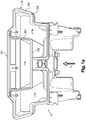
- the figures 1a and 1b are respectively top and side views of an air distribution box provided with a seal according to the invention.
- an air distribution box 1 forming an integral part of an air conditioning unit, constituting a first piece of equipment intended to be assembled in a sealed manner with a second piece of equipment, not shown in the figures, such as for example a dashboard and / or a motor vehicle air intake box, comprising an interface adapted to receive the first equipment.
- the assembly is made by docking the second equipment in a docking direction F1 making a docking angle ⁇ with a normal N to the mounting plane of the air distribution box 1.
- the example shows an embodiment relating to the docking of an air distribution box 1 forming a part of an air conditioning unit.
- the present invention is applicable to any other subassembly of the air conditioning unit to come into contact by docking with an interface of a motor vehicle.
- the present invention is not limited to air conditioning equipment and finds an application when a device must come into contact via an interface with a second equipment by docking and that a seal is required between both equipment.
- the seal between the two devices is made by means of a seal 10.
- the seal 10 consists of a plurality of segments.
- the plurality of segments comprises seal segments 101, 102 and 103 arranged at the periphery of the seal 10, hereinafter referred to as peripheral seal rings 101, 102 and 103, and seal segments. 101 'and 102' disposed within the periphery of the seal 10, hereinafter referred to as inner seal rings 101 'and 102'.
- peripheral seal segments 101, 102 and 103 are intended to ensure the tightness of the first device, in this case the air distribution box 1, with the second equipment, in this case the instrument panel and / or the air intake box.
- the inner seal segments 101 'and 102' complete the sealing function between the two devices. They also provide an internal sealing function in order to avoid air exchanges between air outlets of the air distribution box 1.
- the inner seal segments 101 'and 102' make it possible to create a sealed separation between a defrost outlet 11 and two aeration outlets 12 and 13, disposed on either side of the defrost outlet 11, according to the present embodiment.
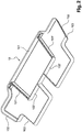
- the figure 2 is a perspective view of the seal according to the invention in which the air distribution box 1 is not shown. This illustration makes it possible to better identify the seal 10 and the various seal segments 101, 102, 103, 101 'and 102' constituting it.
- each seal segment whether the peripheral seal segments 101, 102 and 103 and / or the inner seal segments 101 'and 102', comprises at least one lip 110.
- An embodiment of the lip 110 is presented to the figure 3a .
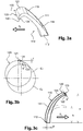
- the figure 3a is a perspective view of a first embodiment of a lip 110 of a seal according to the invention.
- the lip 110 has a lip body 111 which extends from a lip foot 112 intended to be fixed on the first piece of equipment, the occurrence, in the exemplary embodiment of the figure 3a , the air distribution box 1.
- the mode of attachment of the lip 110 on the air distribution box 1 may be overmolding, according to a preferred embodiment.
- the lip body 111 of the lip 110 has a substantially cylindrical inclined profile whose generatrices are represented by a first generatrix line 113 and a second generatrix line 114.
- the lip body 111 of the lip 110 In docking phase of the first equipment with the second equipment, the lip body 111 of the lip 110 is able to tilt.
- the inclination direction of the lip body 111 with respect to the lip foot 112 is indicated by the arrow F2.
- the lip body 111 extends in the inclination direction F2 by a leading edge 120 having a docking area 121 intended for contact the lip 110 with the second equipment, in this case with the dashboard and / or the air intake box, when assembling the two devices together.
- the docking area 121 is a part of the lip 110 located at a distance furthest from the lip foot 112 of the lip 110.
- the lip 110 is made of a deformable plastic material, especially elastomeric thermoplastic (TPE).
- TPE elastomeric thermoplastic
- the seal segments together constituting the seal 10 are arranged so that the lip bodies 111 corresponding are all able to deform in the associated inclination direction F2.
- the deformation of the lip bodies 111 of the peripheral seal segments 101, 102 and 103 and the inner seal segments 101 'and 102' in the associated inclination direction F2 is ensured regardless of the orientation of the docking direction F1 , that is to say for any value of the docking angle ⁇ , which can vary from 0 to 90 °.
- This advantage primarily related to the position of the seal segments along the seal 10, can be further amplified by the effect of "casing” conferred on the lips 110 of the seal segments.
- the effect of "casing” consists, as we can see on the figure 3a to give an evolutionary section to the profile of the lip body 111.
- the profile of the lip body 111 decreases from the lip foot 112 to the leading edge 120 of the lip 110.
- the contact of the docking surface of the second equipment at the docking area 121 first orients the deformation of the lip 110 in the direction of bending in the tilt direction. F2. Then, the evolutionary profile of the lip body 111 accompanies and continues the deformation given by the leading edge 120.
- the leading edge 120 of the lip 110 also has an anti-overturn zone 122.
- the anti-rollover zone 122 is disposed at an end 123 of the lip 110 located opposite the lip foot 112 of the lip 110
- the anti-rollover zone 122 exceeds, in the direction of evolution of the profile of the lip body 111, the zone docking 121 and thus a point of contact between the lip 110 and the second equipment.
- the anti-rollover zone 122 prevents the lip 110 from being turned over in the event of strong fluctuations during the docking phase.
- the anti-rollover zone 122 extends the docking area 121 and constitutes a change of direction of the evolution of the profile of the lip body 111.
- the anti-rollover zone 122 is thus oriented towards the lip foot 112 of the body of the body. lip 111.
- Figures 3b and 3c are dimensioning diagrams respectively of the leading edge 120 of the lip 110 of the figure 3a and lip 110 of the figure 3a .
- the anti-rollover zone 122 has a circular profile.
- figure 3b allows to give dimensioning elements of the leading edge 120, the docking zone 121 and the anti-rollover zone 122.
- the end 123 of the lip 110 is of circular shape so that the anti-rollover zone 122 is in a circular section 124 having a diameter d.
- the evolutionary profile of the docking zone 121 and the anti-rollover zone 122 is defined by two circles C1 and C2 that are off-center with respect to each other.
- the anti-rollover zone 122 has an offset 'f' with respect to the docking area 121.
- the shift 'f' between the docking area 121 and the diameter of the anti-roll zone -return 122 is defined according to the relation: 0 , 5 d ⁇ f ⁇ 5.
- the lip 110 is shown in a rest position (in strong lines on the figure 3c ), that is to say prior to any docking step of the first equipment on the second equipment, and in a bending position after docking (in fine lines on the figure 3c ).
- the lip foot 112 of the lip 110 has a width 'w' and has a rest height 'H' and a bending height 'h'.
- the lip 110 has a compression ratio ' ⁇ '.
- the figure 3d illustrates a perspective view of an alternative embodiment of a seal according to the present invention.
- the docking area 121 and the anti-rollover zone 122 are inscribed in an elliptical profile 125.
- the elliptical profile 125 is found in the example of seal segment 10 of the figure 4 which has a perspective view of a double lip seal segment in accordance with the present invention.
- the figure 4 illustrates, for example, the structure of the inner seal segment 101 '.
- the seal segment 101 ' comprises two lips 110 and 110' extending parallel to each other.
- the lip 110 respectively 110 ', comprises a lip foot 112, respectively 112', a lip body 111, respectively 111 ', and a leading edge 120, respectively 120'.
- the leading edges 120 and 120 'of the two lips 110 and 110' are arranged facing one another.
- This type of joint segments 101 ' is well suited for sealing between two different outlets of the air distribution box 1, as shown in FIG. figure 1a , while the single-lip seal segments are more suitable for sealing at the periphery of the air distribution box 1.
- the figure 4 also shows that transverse walls 200.
- the transverse walls 200 connect the lip bodies 111 and 111 'of the two lips 110 and 110'.
- the transverse walls 200 form baffles between the lip bodies 111 and 111 'of the lips 110 and 110'.
- the baffles are spaced apart, for example, by a step ranging from one to two times the distance between the generating lines of the two lips 110 and 110 '.
- a step ranging from one to two times the distance between the generating lines of the two lips 110 and 110 '.
- the transverse walls 200 have a median height 'h', a thickness' t ', and the lips 110 and 110' have a half-height wall thickness' T '.
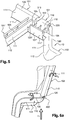
- the figure 5 is a perspective view showing a seal segment having compensation apertures according to the present invention.
- the figure 5 illustrates a particularly advantageous arrangement of the invention to remedy, in particular, flatness defects of the docking surface of the second equipment, in this case the dashboard and / or the air intake box , which can lead to major leaks and therefore severely affect the tightness of the assembly of the two devices.
- the compensation openings 310 and 320 allow compensation of the flatness defect. It emerges that the compensation openings 310 and 320 provide the seal segment 101 with the necessary flexibility enabling the lip 110 to best apply against the docking surface of the second equipment, here the instrument panel and / or the housing air inlet.
- the auxiliary seal ring segment 101 "constitutes with the lip 110 a baffled double lip box of the type described with reference to FIG. figure 4 .
- the compensating apertures 310 and 320 are arranged in the peripheral seal segment 101 which faces the auxiliary seal segment 101.
- Ribs 105 comparable to the transverse walls 200, connect the peripheral seal segment 101 and the auxiliary sealing ring segment 101 ".
- the ribs 105 may have the same dimensional properties as the transverse walls 200.
- auxiliary seal ring segment 101 lies in the orientation of the leading edge 120" of the auxiliary seal ring segment 101 "and the lip body profile 111" of the auxiliary seal ring segment.
- the auxiliary sealing ring segment 101 is such that the orientation of its leading edge 120" and the profile of its lip body 111 "is in the same direction as the orientation of the leading edge 120 and the profile of the lip body 111 of the peripheral seal segment 101.
- its orientations are identical so that the leading edge 120 "of the auxiliary seal ring segment 101" is parallel to the leading edge 120 of the peripheral seal segment 101 and the lip body 111 "of the auxiliary seal ring segment 101” is parallel to the lip body 111 of the peripheral seal segment 101.
- Another means of sealing the compensating apertures 310 and 320 is to provide the compensation apertures 310 and 320 with a flexible sealing film making it possible at the same time to prevent any leakage at through the lip 110 while maintaining the openings 310 and 320 the necessary flexibility, including the compensation of flatness defects.
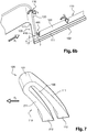
- the figure 6a is a perspective view from above of two adjacent joint segments 102 and 103 in accordance with the present invention.
- the figure 6b is a second side perspective view of the joint segments 102 and 103 of the figure 6a .
- the lip 110 of the peripheral seal segment 103 flexes in the direction of the arrow F3, defining a first direction of flexion F3, according to the general mechanism of deformation which has been described previously, namely orientation of the bending by the leading edge 120 of the peripheral seal segment 103 and accompanying flexion by the evolutive section of the lip body profile 111 of the peripheral seal segment 103.
- a cutout 400 is provided at the intersection between the peripheral seal segment 103 and the peripheral seal segment 102.
- the cutout 400 is formed along the body of the lip 111 of the peripheral seal segment 103.
- the peripheral seal segment 102 in turn deflects in the direction of the arrow F4, defining a second direction of flexion F4, by the combination of two actions: on the one hand, the docking proper on the leading edge 120 of the peripheral seal segment 102 followed by bending of the lip body 111 of the peripheral seal segment 102, and secondly the driving effect of the lip 110 of the peripheral seal segment 103 contacting the lip 110 of the peripheral seal segment 102.
- a sealing wall 410 may be added in the cutout 400.
- the sealing wall 410 has a median height 'h' ', a thickness' t'.
- the lip 110 has a wall thickness at half height 'T'.
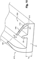
- FIG. 7 is seen in perspective of a third embodiment of a lip of a closed tube gasket according to the invention.
- the figure 7 illustrates another way of absorbing random random movements of assembly, under the combined effect of the pressure and random movements of assembly in the three dimensions of the space, which can cause the folding of the lip 110 in the opposite direction to the direction of inclination F2.
- the lip 110 comprises a first and second leg 112 and 212 in connection with the first equipment, in this case the air distributor housing 1.
- Lip 110 comprises, analogously to the example of figure 3a a first lip body 111 extending from the first lip foot 112.
- the lip body 111 extends in the inclination direction F2 by a leading edge 120 having a docking area 121 for making contact with the lip 110 with the second equipment, in this case with the dashboard and / or the air intake box when assembling the two devices together.
- the embodiment of the figure 7 differs from the lip according to the figure 3a herewith a second lip body 211 extending from the leading edge 120 of the lip 110 to the second leg 212.
- the second lip body 211 is also in connection with the second leg 212.
- the lip 110 thus forms a closed tube 130.
- the second lip body 211 acts as a retainer of the leading edge 120 in the event of force exerted on the lip 110 to return the seal.
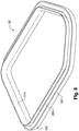
- the figure 8 is a perspective view of a variant of a seal according to the present invention. On the figure 8 is shown a seal 20 constituting a variant of the seal 10 shown on the figure 1 .
- the seal 20 has linear segments 501 and corner segments 502.
- a joint segment whether it is a linear segment 501 or an angle segment 502, comprises two lips, namely, on the one hand, a main lip 510, of the same type as the lips 110 and 110 'presented on the Figures 3a to 3d and in figure 4 , and, secondly, a secondary lip 520 also of deformable material, arranged parallel to the main lip 510.
- the secondary lip 520 has a lip body 511 which extends from a lip 512, intended to be attached to the air distribution box 1, inside the profile.
- cylindrical of the main lip 510 according to a profile also cylindrical inclined in a second inclination direction F5 opposite to the inclination direction F2 of the main lip 510.
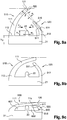
- the Figures 9a to 9c are sectional views illustrating different stages of implementation of the seal of the figure 8 .
- the main lip 510 and the secondary lip 520 are configured so that, when docking the second equipment on the docking area 121 of the leading edge 120 of the main lip 510, the lip body 511 of the secondary lip 520 is flexibly deformed in the second inclination direction F5 under the crushing force exerted by the lip body 111 of the main lip 510, which then covers the lip body 511 of the secondary lip 520.
- the main lip 510 and the secondary lip 520 form inside the seal segments a tubular assembly 600 sealingly closed in that the lip body 511 of the secondary lip 520 exerts a bearing force on the lip body 111 of the main lip 510 by resilient bending.
- the tubular assembly 600 then forms an acoustic barrier capable of absorbing the noise generated by the components of the air distribution box 1 and prevent them from propagating inside the passenger compartment of the vehicle.
- the contact is improved between the main lip 510 and the docking surface of the second equipment. , which increases the tightness of the seal and reduces the acoustic noise that may result from a lack of sealing at this level.
- the main lip 510 is disposed on the seal segment arranged on the inside of the gasket 20, while the secondary lip 520 is disposed on the gasket segment arranged on the outside of the gasket 20.
- the figure 10 is a perspective view of a section of the joint of the figure 8 .
- the Figures 9a and 10 show that the cylindrical profile of the lip body 511 of the secondary lip 520 has a proximal portion 514 directed towards the leading edge 120 of the main lip 510, the angle ⁇ between the proximal portion 514 and the leading edge 120 is preferably greater than or equal to 90 °. In this way, it is ensured that, during docking, the main lip 510 can cover the secondary lip 520 and force it to bend towards the inside of the seal 20, without it being able to turn towards the outside. .
- the cylindrical profile of the lip body 511 of the secondary lip 520 has a distal portion 516 inclined relative to the proximal portion 514 in the second inclination direction F5 of the secondary lip 520.
- the angle ⁇ between the proximal portion 514 and the distal portion 516 of the secondary lip 520 varies for example between 5 and 15 °.
- a central rib 22 is formed longitudinally on the single base 21 so as to delimit, in the tubular assembly 600, two tubes 601 and 602 separated by the central rib 22, so as to increase the acoustic absorption of the gasket. sealing by multiplying the number of acoustic barriers.
- two or more ribs of this type are formed longitudinally on the single base 21 so as to delimit, in the tubular assembly 600, two tubes 601 and 602 separated by the central rib 22, so as to increase the acoustic absorption of the gasket. sealing by multiplying the number of acoustic barriers.
- two or more ribs of this type are examples of this type.
- the central rib 22 forms a stop for the main lip 510 when docking the second equipment.
- the lip body 111 of the main lip 510 is thus subjected from the central rib 22 to a stress which increases the contact force of the lip against the docking surface of the second equipment. This results in a better seal of the seal 20.
- the respective lip bodies 111 and 511 of the main lip 510 and the secondary lip 520 have contact zones 115 and 515 respective bearing anti-friction treatment.
- the anti-friction treatment consists in conferring on the contact zones 115 and 515 surface conditions of appropriate roughness by sanding the corresponding walls of the mold. It is also possible to produce the seal in a thermoplastic elastomer material containing siloxane.
- the lip body 111 of the main lip 510 is made longer in the direction of extension of the lip body 111 than in the linear segments 501 to prevent shortening of the lip in this zone, in particular by contraction, does not prevent the secondary lip 520 from being covered by the main lip 510 during docking.
- the present invention is particularly adapted to a seal making it possible to ensure a seal between, in particular, an air distribution box and a dashboard and / or an air intake box of air conditioning equipment.
Landscapes
- Engineering & Computer Science (AREA)
- Mechanical Engineering (AREA)
- General Engineering & Computer Science (AREA)
- Physics & Mathematics (AREA)
- Thermal Sciences (AREA)
- Gasket Seals (AREA)
Claims (19)
- Dichtanordnung umfassend einen Dichtungsring (10, 20), eine erste Vorrichtung (1), eine zweite Vorrichtung, wobei die erste Vorrichtung (1) den Dichtungsring (10, 20) trägt, und die zweite Vorrichtung ausgebildet ist, durch Ankoppeln in einer vorgegebenen Ankoppelrichtung (F1) in Kontakt mit dem Dichtungsring (10, 20) zu kommen,
wobei der Dichtungsring (10, 20) aus einer Mehrheit von Dichtsegmenten (101, 102, 103, 101', 102', 501, 502) umfassend jeweils wenigstens eine Lippe (110, 110', 510) aus verformbarem Material besteht, wobei die Lippe (110, 110', 510) Folgendes aufweist:- einen sich von einem an der ersten Vorrichtung (1) befestigten Fuß (112, 112', 512) in einem in einer vorgegebenen Neigungsrichtung (F2) geneigten zylindrischen Profil erstreckenden Lippenkörper (111, 111', 111", 511),- eine den Lippenkörper (110, 110', 510) in der vorgegebenen Neigungsrichtung (F2) verlängernde Vorderkante (120, 120', 120"), wobei die Vorderkante (120, 120', 120") einen zum Herstellen des Kontakts mit der zweiten Vorrichtung vorgesehenen Ankoppelbereich (121) aufweist,wobei die Dichtsegmente (101, 102, 103, 101', 102', 501, 502) so angeordnet sind, dass für jede Ausrichtung (θ) der Ankoppelrichtung (F1) der zweiten Vorrichtung die Lippenkörper (111, 111', 111", 511) der Dichtsegmente (101, 102, 103, 101', 102', 501, 502) sich durch Biegung in der entsprechenden Neigungsrichtung (F2) verformen können, und wobei die Dichtsegmente (501, 502) jeweils- einerseits die Lippe (510) aus verformbarem Material, die sogenannte Hauptlippe, und- andererseits eine Sekundärlippe (520) aus verformbarem Material und einen sich von einem an der ersten Vorrichtung (1) befestigten Lippenfuß (512) im Inneren des zylindrischen Profils der Hauptlippe (510) in einem in einer zweiten Neigungsrichtung (F5) entgegengesetzt zur Neigungsrichtung (F2) der Hauptlippe (510) geneigten zylindrischen Profil erstreckenden Lippenkörper (511) aufweisend, umfassen, so dass bei einem Ankoppeln der zweiten Vorrichtung der Lippenkörper (511) der Sekundärlippe (510) sich durch Biegung in der zweiten Neigungsrichtung (F5) unter der vom Lippenkörper (111) der Hauptlippe (510) ausgeübten Quetschkraft verformt,wobei die Lippenfüße (111, 511) der Hauptlippe (510) und der Sekundärlippe (520) in einer einmaligen Basis (21) vereint sind, und wobei die einmalige Basis (21) wenigstens eine Mittelrippe (22) trägt, auf der sich die Hauptlippe (510) beim Ankoppeln der zweiten Vorrichtung auf der Hauptlippe (510) abstützt. - Dichtanordnung nach Anspruch 1, wobei das zylindrische Profil des Lippenkörpers (111, 111', 111") einen sich entwickelnden Querschnitt aufweist, der vom Fuß (112, 112') des Lippenkörpers (111, 111', 111") zur Vorderkante (120, 120', 120") abnimmt.
- Dichtanordnung nach Anspruch 1 oder 2, wobei die Vorderkante (120, 120', 120") einen den Ankoppelbereich (121) in Richtung des Fußes (112, 112') des Lippenkörpers (111, 111', 111") verlängernden Umschlagschutzbereich (122) der Lippe (110, 110') aufweist.
- Dichtanordnung nach Anspruch 3, wobei der Umschlagschutzbereich (122) ein kreisförmiges Profil aufweist.
- Dichtanordnung nach Anspruch 3, wobei der Ankoppelbereich (121) und/oder der Umschlagschutzbereich (122) ein elliptisches Profil aufweisen.
- Dichtanordnung nach einem der Ansprüche 1 bis 5, wobei die Hauptlippe (510) und die Sekundärlippe (520) wenigstens ein geschlossenes Rohr (601, 602) in den Dichtsegmenten (501, 502) bilden.
- Dichtanordnung nach einem der vorausgehenden Ansprüche, wobei die Hauptlippe (510) und die Sekundärlippe (520) jeweils auf den innerhalb und außerhalb des Dichtungsrings (20) angeordneten Dichtsegmenten (501, 502) angeordnet sind.
- Dichtanordnung nach einem der vorausgehenden Ansprüche, wobei das zylindrische Profil des Lippenkörpers (511) der Sekundärlippe (520) einen zur Vorderkante (120) der Hauptlippe (510) gerichteten proximalen Teil (514) aufweist.
- Dichtanordnung nach Anspruch 8, wobei der proximale Teil (514) mit der Vorderkante (120) der Hauptlippe (510) einen Winkel (β) größer gleich 90° bildet.
- Dichtanordnung nach Anspruch 8 oder 9, wobei das zylindrische Profil des Lippenkörpers (511) der Sekundärlippe (520) einen zum proximalen Teil (514) in der zweiten Neigungsrichtung (F5) der Sekundärlippe (520) geneigten distalen Teil (516) aufweist.
- Dichtanordnung nach Anspruch 10, wobei der distale Teil (516) des Lippenkörpers (511) der Sekundärlippe (520) mit dem proximalen Teil (514) des Lippenkörpers (511) der Sekundärlippe (520) einen Winkel (α) zwischen 5 und 15° bildet.
- Dichtanordnung nach einem der vorausgehenden Ansprüche, wobei das zylindrische Profil der Hauptlippe (510) breiter in der Verlängerungsrichtung des Lippenkörpers (111) in einem Winkelsegment (502) als in einem linearen Segment (501) ist.
- Dichtanordnung nach einem der vorausgehenden Ansprüche, wobei eines der Dichtsegmente (101, 102, 103, 101', 102', 501, 502) wenigstens eine Ausgleichsöffnung (310, 320) umfasst.
- Dichtanordnung nach Anspruch 13, wobei ein Hilfsdichtsegment (101") gegenüber der Ausgleichsöffnung (310, 320) angeordnet ist.
- Dichtanordnung nach Anspruch 13, wobei die Öffnung (310, 320) mit einem elastischen Dichtfilm ausgestattet ist.
- Dichtanordnung nach einem der vorausgehenden Ansprüche, umfassend wenigstens ein Paar von angrenzenden Dichtsegmenten (101, 102, 103), wobei die Lippe (110) eines Dichtsegments (102) einen entlang des Lippenkörpers (111) des Dichtsegments (102) angeordneten Ausschnitt (400) umfasst.
- Dichtanordnung nach Anspruch 16, wobei der Ausschnitt (400) eine Dichtwand (410) zwischen den Dichtsegmenten (102, 103) angrenzend an ein gleiches Paar von Dichtsegmenten (102, 103) umfasst.
- Dichtanordnung nach einem der vorausgehenden Ansprüche, wobei die Vorderkante (120) der Lippe (110) durch einen zweiten Lippenkörper (211) zu einem an der ersten Vorrichtung (1) befestigten zweiten Fuß (212) verlängert ist, um ein geschlossenes Rohr (130) zu bilden.
- Dichtanordnung nach einem der vorausgehenden Ansprüche, wobei der Dichtungsring (10, 20) aus einem Elastomer-Thermoplast besteht.
Applications Claiming Priority (3)
| Application Number | Priority Date | Filing Date | Title |
|---|---|---|---|
| FR0900659A FR2942287B1 (fr) | 2009-02-13 | 2009-02-13 | Joint d'etancheite |
| FR0903671A FR2942286B1 (fr) | 2009-02-13 | 2009-07-24 | Joint d'etancheite |
| PCT/EP2010/051514 WO2010092024A1 (fr) | 2009-02-13 | 2010-02-08 | Joint d'étanchéité |
Publications (2)
| Publication Number | Publication Date |
|---|---|
| EP2396573A1 EP2396573A1 (de) | 2011-12-21 |
| EP2396573B1 true EP2396573B1 (de) | 2017-11-15 |
Family
ID=41125430
Family Applications (1)
| Application Number | Title | Priority Date | Filing Date |
|---|---|---|---|
| EP10702702.1A Active EP2396573B1 (de) | 2009-02-13 | 2010-02-08 | Dichtungsanordnung |
Country Status (3)
| Country | Link |
|---|---|
| EP (1) | EP2396573B1 (de) |
| FR (2) | FR2942287B1 (de) |
| WO (1) | WO2010092024A1 (de) |
Family Cites Families (7)
| Publication number | Priority date | Publication date | Assignee | Title |
|---|---|---|---|---|
| FR2480892A1 (fr) * | 1980-04-18 | 1981-10-23 | Ferodo Sa | Dispositif formant etancheite au debouche d'une canalisation, par exemple d'un boitier d'une installation de chauffage de l'habitacle d'un vehicule automobile |
| FR2747172B1 (fr) * | 1996-04-03 | 1998-05-29 | Heurteaux | Bande profilee de largeur modulable, en particulier pour la formation d'un joint ou d'une goulotte |
| DE29716379U1 (de) * | 1997-09-11 | 1997-11-27 | Meteor Gummiwerke K. H. Bädje GmbH & Co, 31167 Bockenem | Kraftfahrzeug-Dichtungsprofil |
| AUPQ945800A0 (en) * | 2000-08-16 | 2000-09-07 | James Hardie International Finance B.V. | A seal |
| DE102005054070A1 (de) * | 2005-11-12 | 2007-05-24 | Daimlerchrysler Ag | Dichtung für einen Verbindungsflasch einer Belüftungsanlage eines Fahrzeugs |
| DE102006016854B3 (de) * | 2006-04-07 | 2007-07-12 | Magna Car Top Systems Gmbh | Dichtungselement zwischen zwei relativbeweglichen Fahrzeugbauteilen |
| DE102007036471A1 (de) * | 2007-08-01 | 2009-02-05 | Behr Gmbh & Co. Kg | Kanal, insbesondere zur Luftführung |
-
2009
- 2009-02-13 FR FR0900659A patent/FR2942287B1/fr not_active Expired - Fee Related
- 2009-07-24 FR FR0903671A patent/FR2942286B1/fr not_active Expired - Fee Related
-
2010
- 2010-02-08 WO PCT/EP2010/051514 patent/WO2010092024A1/fr not_active Ceased
- 2010-02-08 EP EP10702702.1A patent/EP2396573B1/de active Active
Non-Patent Citations (1)
| Title |
|---|
| None * |
Also Published As
| Publication number | Publication date |
|---|---|
| FR2942286A1 (fr) | 2010-08-20 |
| FR2942287B1 (fr) | 2012-08-10 |
| EP2396573A1 (de) | 2011-12-21 |
| FR2942286B1 (fr) | 2013-01-25 |
| WO2010092024A1 (fr) | 2010-08-19 |
| FR2942287A1 (fr) | 2010-08-20 |
Similar Documents
| Publication | Publication Date | Title |
|---|---|---|
| CN101522449B (zh) | 用于机动车内部压力释放的通风组件 | |
| WO2014006305A1 (fr) | Climatiseur, notamment pour véhicule automobile | |
| FR2959382A1 (fr) | Interface homme-machine a boitier renforce | |
| CN108116196B (zh) | 空调调风器 | |
| EP2396573B1 (de) | Dichtungsanordnung | |
| FR2569455A1 (fr) | Joint d'etancheite profile permettant d'assembler deux elements de carter a bords paralleles | |
| WO2012079990A1 (fr) | Dispositif de commande haptique comportant un joint d'étanchéité | |
| EP1919724B1 (de) | Lufttechnisches querglied für ein kraftfahrzeug | |
| FR2925401A1 (fr) | Aerateur de vehicule automobile a etancheite amelioree | |
| EP1818197B1 (de) | Entlüftungsvorrichtung für ein Kraftfahrzeug | |
| FR2947591A1 (fr) | Ensemble forme d'un support-moteur et d'une bague de reception de ce dernier | |
| FR3029706A1 (fr) | Dispositif de traversee d'un faisceau electrique | |
| EP2050607B1 (de) | Lineares Dichtungselement und Kraftfahrzeug, das mit einer solchen Dichtung ausgestattet ist | |
| FR3098467A1 (fr) | Dispositif de restitution sonore à effets lumineux périphériques passifs | |
| WO2021084179A1 (fr) | Paroi poreuse et boitier d'installation de chauffage et/ou ventilation et/ou climatisation correspondant | |
| FR2983277A1 (fr) | Dispositif d'emmanchement de deux pieces rigides, notamment pour l'assemblage d'une gaine de climatisation sur une bouche d'aeration, notamment pour vehicule automobile | |
| FR3030377A1 (fr) | Aerateur pour l'habitacle d'un vehicule automobile | |
| FR3110521A1 (fr) | Ensemble d'habillage intérieur de véhicule à moteur comprenant un ensemble canal-trappe pour coussin gonflable | |
| FR2896742A1 (fr) | Console centrale a volume de rangement pour vehicule automobile | |
| EP2183830B1 (de) | In einer automobilwand integrierter verkabelungsring | |
| EP4703211A1 (de) | Durchführung für mindestens ein kabel und/oder rohr | |
| WO2025040372A1 (fr) | Systeme d'etancheite interpose entre une installation de ventilation, chauffage et/ou climatisation et une paroi d'un vehicule. | |
| EP1705779B1 (de) | Antriebseinheit mit einem in einem akustischen Strahlungsschwächungshohlraum abgestützen Elektromotor. | |
| WO2025238254A1 (fr) | Dispositif lumineux avec un système d'aération pour un véhicule automobile | |
| FR3151072A1 (fr) | Conduit d’air réalisé en deux demi-coques |
Legal Events
| Date | Code | Title | Description |
|---|---|---|---|
| PUAI | Public reference made under article 153(3) epc to a published international application that has entered the european phase |
Free format text: ORIGINAL CODE: 0009012 |
|
| 17P | Request for examination filed |
Effective date: 20110808 |
|
| AK | Designated contracting states |
Kind code of ref document: A1 Designated state(s): AT BE BG CH CY CZ DE DK EE ES FI FR GB GR HR HU IE IS IT LI LT LU LV MC MK MT NL NO PL PT RO SE SI SK SM TR |
|
| DAX | Request for extension of the european patent (deleted) | ||
| 17Q | First examination report despatched |
Effective date: 20140225 |
|
| GRAP | Despatch of communication of intention to grant a patent |
Free format text: ORIGINAL CODE: EPIDOSNIGR1 |
|
| INTG | Intention to grant announced |
Effective date: 20170629 |
|
| GRAS | Grant fee paid |
Free format text: ORIGINAL CODE: EPIDOSNIGR3 |
|
| GRAA | (expected) grant |
Free format text: ORIGINAL CODE: 0009210 |
|
| AK | Designated contracting states |
Kind code of ref document: B1 Designated state(s): AT BE BG CH CY CZ DE DK EE ES FI FR GB GR HR HU IE IS IT LI LT LU LV MC MK MT NL NO PL PT RO SE SI SK SM TR |
|
| REG | Reference to a national code |
Ref country code: CH Ref legal event code: EP Ref country code: GB Ref legal event code: FG4D Free format text: NOT ENGLISH Ref country code: AT Ref legal event code: REF Ref document number: 946619 Country of ref document: AT Kind code of ref document: T Effective date: 20171115 |
|
| REG | Reference to a national code |
Ref country code: IE Ref legal event code: FG4D Free format text: LANGUAGE OF EP DOCUMENT: FRENCH |
|
| REG | Reference to a national code |
Ref country code: DE Ref legal event code: R096 Ref document number: 602010046688 Country of ref document: DE |
|
| REG | Reference to a national code |
Ref country code: FR Ref legal event code: PLFP Year of fee payment: 9 |
|
| REG | Reference to a national code |
Ref country code: NL Ref legal event code: MP Effective date: 20171115 |
|
| REG | Reference to a national code |
Ref country code: LT Ref legal event code: MG4D |
|
| REG | Reference to a national code |
Ref country code: AT Ref legal event code: MK05 Ref document number: 946619 Country of ref document: AT Kind code of ref document: T Effective date: 20171115 |
|
| PG25 | Lapsed in a contracting state [announced via postgrant information from national office to epo] |
Ref country code: NL Free format text: LAPSE BECAUSE OF FAILURE TO SUBMIT A TRANSLATION OF THE DESCRIPTION OR TO PAY THE FEE WITHIN THE PRESCRIBED TIME-LIMIT Effective date: 20171115 Ref country code: NO Free format text: LAPSE BECAUSE OF FAILURE TO SUBMIT A TRANSLATION OF THE DESCRIPTION OR TO PAY THE FEE WITHIN THE PRESCRIBED TIME-LIMIT Effective date: 20180215 Ref country code: ES Free format text: LAPSE BECAUSE OF FAILURE TO SUBMIT A TRANSLATION OF THE DESCRIPTION OR TO PAY THE FEE WITHIN THE PRESCRIBED TIME-LIMIT Effective date: 20171115 Ref country code: LT Free format text: LAPSE BECAUSE OF FAILURE TO SUBMIT A TRANSLATION OF THE DESCRIPTION OR TO PAY THE FEE WITHIN THE PRESCRIBED TIME-LIMIT Effective date: 20171115 Ref country code: SE Free format text: LAPSE BECAUSE OF FAILURE TO SUBMIT A TRANSLATION OF THE DESCRIPTION OR TO PAY THE FEE WITHIN THE PRESCRIBED TIME-LIMIT Effective date: 20171115 Ref country code: FI Free format text: LAPSE BECAUSE OF FAILURE TO SUBMIT A TRANSLATION OF THE DESCRIPTION OR TO PAY THE FEE WITHIN THE PRESCRIBED TIME-LIMIT Effective date: 20171115 |
|
| PG25 | Lapsed in a contracting state [announced via postgrant information from national office to epo] |
Ref country code: LV Free format text: LAPSE BECAUSE OF FAILURE TO SUBMIT A TRANSLATION OF THE DESCRIPTION OR TO PAY THE FEE WITHIN THE PRESCRIBED TIME-LIMIT Effective date: 20171115 Ref country code: GR Free format text: LAPSE BECAUSE OF FAILURE TO SUBMIT A TRANSLATION OF THE DESCRIPTION OR TO PAY THE FEE WITHIN THE PRESCRIBED TIME-LIMIT Effective date: 20180216 Ref country code: BG Free format text: LAPSE BECAUSE OF FAILURE TO SUBMIT A TRANSLATION OF THE DESCRIPTION OR TO PAY THE FEE WITHIN THE PRESCRIBED TIME-LIMIT Effective date: 20180215 Ref country code: HR Free format text: LAPSE BECAUSE OF FAILURE TO SUBMIT A TRANSLATION OF THE DESCRIPTION OR TO PAY THE FEE WITHIN THE PRESCRIBED TIME-LIMIT Effective date: 20171115 Ref country code: AT Free format text: LAPSE BECAUSE OF FAILURE TO SUBMIT A TRANSLATION OF THE DESCRIPTION OR TO PAY THE FEE WITHIN THE PRESCRIBED TIME-LIMIT Effective date: 20171115 |
|
| PG25 | Lapsed in a contracting state [announced via postgrant information from national office to epo] |
Ref country code: CZ Free format text: LAPSE BECAUSE OF FAILURE TO SUBMIT A TRANSLATION OF THE DESCRIPTION OR TO PAY THE FEE WITHIN THE PRESCRIBED TIME-LIMIT Effective date: 20171115 Ref country code: EE Free format text: LAPSE BECAUSE OF FAILURE TO SUBMIT A TRANSLATION OF THE DESCRIPTION OR TO PAY THE FEE WITHIN THE PRESCRIBED TIME-LIMIT Effective date: 20171115 Ref country code: CY Free format text: LAPSE BECAUSE OF FAILURE TO SUBMIT A TRANSLATION OF THE DESCRIPTION OR TO PAY THE FEE WITHIN THE PRESCRIBED TIME-LIMIT Effective date: 20171115 Ref country code: DK Free format text: LAPSE BECAUSE OF FAILURE TO SUBMIT A TRANSLATION OF THE DESCRIPTION OR TO PAY THE FEE WITHIN THE PRESCRIBED TIME-LIMIT Effective date: 20171115 Ref country code: SK Free format text: LAPSE BECAUSE OF FAILURE TO SUBMIT A TRANSLATION OF THE DESCRIPTION OR TO PAY THE FEE WITHIN THE PRESCRIBED TIME-LIMIT Effective date: 20171115 |
|
| REG | Reference to a national code |
Ref country code: DE Ref legal event code: R097 Ref document number: 602010046688 Country of ref document: DE |
|
| PG25 | Lapsed in a contracting state [announced via postgrant information from national office to epo] |
Ref country code: RO Free format text: LAPSE BECAUSE OF FAILURE TO SUBMIT A TRANSLATION OF THE DESCRIPTION OR TO PAY THE FEE WITHIN THE PRESCRIBED TIME-LIMIT Effective date: 20171115 Ref country code: IT Free format text: LAPSE BECAUSE OF FAILURE TO SUBMIT A TRANSLATION OF THE DESCRIPTION OR TO PAY THE FEE WITHIN THE PRESCRIBED TIME-LIMIT Effective date: 20171115 Ref country code: SM Free format text: LAPSE BECAUSE OF FAILURE TO SUBMIT A TRANSLATION OF THE DESCRIPTION OR TO PAY THE FEE WITHIN THE PRESCRIBED TIME-LIMIT Effective date: 20171115 Ref country code: PL Free format text: LAPSE BECAUSE OF FAILURE TO SUBMIT A TRANSLATION OF THE DESCRIPTION OR TO PAY THE FEE WITHIN THE PRESCRIBED TIME-LIMIT Effective date: 20171115 |
|
| REG | Reference to a national code |
Ref country code: CH Ref legal event code: PL |
|
| PLBE | No opposition filed within time limit |
Free format text: ORIGINAL CODE: 0009261 |
|
| STAA | Information on the status of an ep patent application or granted ep patent |
Free format text: STATUS: NO OPPOSITION FILED WITHIN TIME LIMIT |
|
| PG25 | Lapsed in a contracting state [announced via postgrant information from national office to epo] |
Ref country code: MC Free format text: LAPSE BECAUSE OF FAILURE TO SUBMIT A TRANSLATION OF THE DESCRIPTION OR TO PAY THE FEE WITHIN THE PRESCRIBED TIME-LIMIT Effective date: 20171115 Ref country code: MT Free format text: LAPSE BECAUSE OF FAILURE TO SUBMIT A TRANSLATION OF THE DESCRIPTION OR TO PAY THE FEE WITHIN THE PRESCRIBED TIME-LIMIT Effective date: 20171115 |
|
| 26N | No opposition filed |
Effective date: 20180817 |
|
| GBPC | Gb: european patent ceased through non-payment of renewal fee |
Effective date: 20180215 |
|
| REG | Reference to a national code |
Ref country code: IE Ref legal event code: MM4A |
|
| REG | Reference to a national code |
Ref country code: BE Ref legal event code: MM Effective date: 20180228 |
|
| PG25 | Lapsed in a contracting state [announced via postgrant information from national office to epo] |
Ref country code: LI Free format text: LAPSE BECAUSE OF NON-PAYMENT OF DUE FEES Effective date: 20180228 Ref country code: LU Free format text: LAPSE BECAUSE OF NON-PAYMENT OF DUE FEES Effective date: 20180208 Ref country code: CH Free format text: LAPSE BECAUSE OF NON-PAYMENT OF DUE FEES Effective date: 20180228 Ref country code: SI Free format text: LAPSE BECAUSE OF FAILURE TO SUBMIT A TRANSLATION OF THE DESCRIPTION OR TO PAY THE FEE WITHIN THE PRESCRIBED TIME-LIMIT Effective date: 20171115 |
|
| PG25 | Lapsed in a contracting state [announced via postgrant information from national office to epo] |
Ref country code: IE Free format text: LAPSE BECAUSE OF NON-PAYMENT OF DUE FEES Effective date: 20180208 |
|
| PG25 | Lapsed in a contracting state [announced via postgrant information from national office to epo] |
Ref country code: BE Free format text: LAPSE BECAUSE OF NON-PAYMENT OF DUE FEES Effective date: 20180228 Ref country code: GB Free format text: LAPSE BECAUSE OF NON-PAYMENT OF DUE FEES Effective date: 20180215 |
|
| PG25 | Lapsed in a contracting state [announced via postgrant information from national office to epo] |
Ref country code: TR Free format text: LAPSE BECAUSE OF FAILURE TO SUBMIT A TRANSLATION OF THE DESCRIPTION OR TO PAY THE FEE WITHIN THE PRESCRIBED TIME-LIMIT Effective date: 20171115 |
|
| PG25 | Lapsed in a contracting state [announced via postgrant information from national office to epo] |
Ref country code: HU Free format text: LAPSE BECAUSE OF FAILURE TO SUBMIT A TRANSLATION OF THE DESCRIPTION OR TO PAY THE FEE WITHIN THE PRESCRIBED TIME-LIMIT; INVALID AB INITIO Effective date: 20100208 Ref country code: PT Free format text: LAPSE BECAUSE OF FAILURE TO SUBMIT A TRANSLATION OF THE DESCRIPTION OR TO PAY THE FEE WITHIN THE PRESCRIBED TIME-LIMIT Effective date: 20171115 |
|
| PG25 | Lapsed in a contracting state [announced via postgrant information from national office to epo] |
Ref country code: MK Free format text: LAPSE BECAUSE OF NON-PAYMENT OF DUE FEES Effective date: 20171115 |
|
| PG25 | Lapsed in a contracting state [announced via postgrant information from national office to epo] |
Ref country code: IS Free format text: LAPSE BECAUSE OF FAILURE TO SUBMIT A TRANSLATION OF THE DESCRIPTION OR TO PAY THE FEE WITHIN THE PRESCRIBED TIME-LIMIT Effective date: 20180315 |
|
| P01 | Opt-out of the competence of the unified patent court (upc) registered |
Effective date: 20230528 |
|
| PGFP | Annual fee paid to national office [announced via postgrant information from national office to epo] |
Ref country code: DE Payment date: 20250212 Year of fee payment: 16 |
|
| PGFP | Annual fee paid to national office [announced via postgrant information from national office to epo] |
Ref country code: FR Payment date: 20250225 Year of fee payment: 16 |