EP2396105B1 - Methanolreinigungsverfahren und -vorrichtung - Google Patents
Methanolreinigungsverfahren und -vorrichtung Download PDFInfo
- Publication number
- EP2396105B1 EP2396105B1 EP09839848.0A EP09839848A EP2396105B1 EP 2396105 B1 EP2396105 B1 EP 2396105B1 EP 09839848 A EP09839848 A EP 09839848A EP 2396105 B1 EP2396105 B1 EP 2396105B1
- Authority
- EP
- European Patent Office
- Prior art keywords
- methanol
- feed
- contaminated
- refining
- column
- Prior art date
- Legal status (The legal status is an assumption and is not a legal conclusion. Google has not performed a legal analysis and makes no representation as to the accuracy of the status listed.)
- Active
Links
- OKKJLVBELUTLKV-UHFFFAOYSA-N Methanol Chemical compound OC OKKJLVBELUTLKV-UHFFFAOYSA-N 0.000 title claims description 214
- 238000000034 method Methods 0.000 title claims description 23
- 238000000746 purification Methods 0.000 title description 7
- 238000004821 distillation Methods 0.000 claims description 15
- 239000002253 acid Substances 0.000 claims description 12
- 239000003921 oil Substances 0.000 claims description 12
- 239000000356 contaminant Substances 0.000 claims description 7
- 238000003860 storage Methods 0.000 claims description 6
- 239000012535 impurity Substances 0.000 claims description 5
- 238000007670 refining Methods 0.000 claims 10
- 238000001816 cooling Methods 0.000 claims 1
- 238000010438 heat treatment Methods 0.000 claims 1
- 238000004064 recycling Methods 0.000 claims 1
- LSDPWZHWYPCBBB-UHFFFAOYSA-N Methanethiol Chemical compound SC LSDPWZHWYPCBBB-UHFFFAOYSA-N 0.000 description 10
- 239000007789 gas Substances 0.000 description 10
- 238000012856 packing Methods 0.000 description 9
- QGZKDVFQNNGYKY-UHFFFAOYSA-N Ammonia Chemical compound N QGZKDVFQNNGYKY-UHFFFAOYSA-N 0.000 description 8
- 238000010992 reflux Methods 0.000 description 8
- XLYOFNOQVPJJNP-UHFFFAOYSA-N water Substances O XLYOFNOQVPJJNP-UHFFFAOYSA-N 0.000 description 8
- 238000004537 pulping Methods 0.000 description 7
- 239000007788 liquid Substances 0.000 description 6
- RWSOTUBLDIXVET-UHFFFAOYSA-N Dihydrogen sulfide Chemical compound S RWSOTUBLDIXVET-UHFFFAOYSA-N 0.000 description 5
- 239000002655 kraft paper Substances 0.000 description 5
- 239000000047 product Substances 0.000 description 5
- 229910021529 ammonia Inorganic materials 0.000 description 4
- 150000001875 compounds Chemical class 0.000 description 4
- OSVXSBDYLRYLIG-UHFFFAOYSA-N dioxidochlorine(.) Chemical compound O=Cl=O OSVXSBDYLRYLIG-UHFFFAOYSA-N 0.000 description 4
- NINIDFKCEFEMDL-UHFFFAOYSA-N Sulfur Chemical class [S] NINIDFKCEFEMDL-UHFFFAOYSA-N 0.000 description 3
- WQOXQRCZOLPYPM-UHFFFAOYSA-N dimethyl disulfide Chemical compound CSSC WQOXQRCZOLPYPM-UHFFFAOYSA-N 0.000 description 3
- 229920005610 lignin Polymers 0.000 description 3
- 238000011084 recovery Methods 0.000 description 3
- 238000000926 separation method Methods 0.000 description 3
- 238000011282 treatment Methods 0.000 description 3
- LFQSCWFLJHTTHZ-UHFFFAOYSA-N Ethanol Chemical compound CCO LFQSCWFLJHTTHZ-UHFFFAOYSA-N 0.000 description 2
- QAOWNCQODCNURD-UHFFFAOYSA-N Sulfuric acid Chemical compound OS(O)(=O)=O QAOWNCQODCNURD-UHFFFAOYSA-N 0.000 description 2
- 239000002535 acidifier Substances 0.000 description 2
- BFNBIHQBYMNNAN-UHFFFAOYSA-N ammonium sulfate Chemical compound N.N.OS(O)(=O)=O BFNBIHQBYMNNAN-UHFFFAOYSA-N 0.000 description 2
- 229910052921 ammonium sulfate Inorganic materials 0.000 description 2
- 239000001166 ammonium sulphate Substances 0.000 description 2
- 235000011130 ammonium sulphate Nutrition 0.000 description 2
- QBWCMBCROVPCKQ-UHFFFAOYSA-N chlorous acid Chemical compound OCl=O QBWCMBCROVPCKQ-UHFFFAOYSA-N 0.000 description 2
- 238000002485 combustion reaction Methods 0.000 description 2
- 238000009833 condensation Methods 0.000 description 2
- 230000005494 condensation Effects 0.000 description 2
- 230000000694 effects Effects 0.000 description 2
- 239000000446 fuel Substances 0.000 description 2
- 150000002576 ketones Chemical class 0.000 description 2
- VNWKTOKETHGBQD-UHFFFAOYSA-N methane Chemical compound C VNWKTOKETHGBQD-UHFFFAOYSA-N 0.000 description 2
- 239000000203 mixture Substances 0.000 description 2
- 239000001117 sulphuric acid Substances 0.000 description 2
- 235000011149 sulphuric acid Nutrition 0.000 description 2
- 239000004155 Chlorine dioxide Substances 0.000 description 1
- 235000008733 Citrus aurantifolia Nutrition 0.000 description 1
- 241000779819 Syncarpia glomulifera Species 0.000 description 1
- 235000011941 Tilia x europaea Nutrition 0.000 description 1
- 150000001298 alcohols Chemical class 0.000 description 1
- 150000001299 aldehydes Chemical class 0.000 description 1
- 230000015572 biosynthetic process Effects 0.000 description 1
- 239000006227 byproduct Substances 0.000 description 1
- 235000019398 chlorine dioxide Nutrition 0.000 description 1
- 230000001010 compromised effect Effects 0.000 description 1
- 239000000470 constituent Substances 0.000 description 1
- 230000007812 deficiency Effects 0.000 description 1
- 238000010494 dissociation reaction Methods 0.000 description 1
- 230000005593 dissociations Effects 0.000 description 1
- 150000002170 ethers Chemical class 0.000 description 1
- 238000001704 evaporation Methods 0.000 description 1
- 239000011552 falling film Substances 0.000 description 1
- 239000002803 fossil fuel Substances 0.000 description 1
- XLYOFNOQVPJJNP-UHFFFAOYSA-M hydroxide Chemical compound [OH-] XLYOFNOQVPJJNP-UHFFFAOYSA-M 0.000 description 1
- 239000004571 lime Substances 0.000 description 1
- 239000007791 liquid phase Substances 0.000 description 1
- 238000004519 manufacturing process Methods 0.000 description 1
- 239000000463 material Substances 0.000 description 1
- 125000000956 methoxy group Chemical group [H]C([H])([H])O* 0.000 description 1
- -1 methoxyl group Chemical group 0.000 description 1
- 239000003345 natural gas Substances 0.000 description 1
- 230000003647 oxidation Effects 0.000 description 1
- 238000007254 oxidation reaction Methods 0.000 description 1
- 239000001739 pinus spp. Substances 0.000 description 1
- 239000002244 precipitate Substances 0.000 description 1
- 238000004076 pulp bleaching Methods 0.000 description 1
- 238000001577 simple distillation Methods 0.000 description 1
- 229940036248 turpentine Drugs 0.000 description 1
- 238000009834 vaporization Methods 0.000 description 1
- 239000003039 volatile agent Substances 0.000 description 1
- 239000002699 waste material Substances 0.000 description 1
Images


Classifications
-
- C—CHEMISTRY; METALLURGY
- C07—ORGANIC CHEMISTRY
- C07C—ACYCLIC OR CARBOCYCLIC COMPOUNDS
- C07C29/00—Preparation of compounds having hydroxy or O-metal groups bound to a carbon atom not belonging to a six-membered aromatic ring
- C07C29/74—Separation; Purification; Use of additives, e.g. for stabilisation
- C07C29/76—Separation; Purification; Use of additives, e.g. for stabilisation by physical treatment
- C07C29/78—Separation; Purification; Use of additives, e.g. for stabilisation by physical treatment by condensation or crystallisation
-
- B—PERFORMING OPERATIONS; TRANSPORTING
- B01—PHYSICAL OR CHEMICAL PROCESSES OR APPARATUS IN GENERAL
- B01D—SEPARATION
- B01D3/00—Distillation or related exchange processes in which liquids are contacted with gaseous media, e.g. stripping
-
- B—PERFORMING OPERATIONS; TRANSPORTING
- B01—PHYSICAL OR CHEMICAL PROCESSES OR APPARATUS IN GENERAL
- B01D—SEPARATION
- B01D3/00—Distillation or related exchange processes in which liquids are contacted with gaseous media, e.g. stripping
- B01D3/14—Fractional distillation or use of a fractionation or rectification column
- B01D3/143—Fractional distillation or use of a fractionation or rectification column by two or more of a fractionation, separation or rectification step
-
- B—PERFORMING OPERATIONS; TRANSPORTING
- B01—PHYSICAL OR CHEMICAL PROCESSES OR APPARATUS IN GENERAL
- B01D—SEPARATION
- B01D5/00—Condensation of vapours; Recovering volatile solvents by condensation
-
- B—PERFORMING OPERATIONS; TRANSPORTING
- B01—PHYSICAL OR CHEMICAL PROCESSES OR APPARATUS IN GENERAL
- B01D—SEPARATION
- B01D5/00—Condensation of vapours; Recovering volatile solvents by condensation
- B01D5/0003—Condensation of vapours; Recovering volatile solvents by condensation by using heat-exchange surfaces for indirect contact between gases or vapours and the cooling medium
- B01D5/0012—Vertical tubes
-
- B—PERFORMING OPERATIONS; TRANSPORTING
- B01—PHYSICAL OR CHEMICAL PROCESSES OR APPARATUS IN GENERAL
- B01D—SEPARATION
- B01D5/00—Condensation of vapours; Recovering volatile solvents by condensation
- B01D5/0057—Condensation of vapours; Recovering volatile solvents by condensation in combination with other processes
- B01D5/006—Condensation of vapours; Recovering volatile solvents by condensation in combination with other processes with evaporation or distillation
- B01D5/0063—Reflux condensation
-
- B—PERFORMING OPERATIONS; TRANSPORTING
- B01—PHYSICAL OR CHEMICAL PROCESSES OR APPARATUS IN GENERAL
- B01D—SEPARATION
- B01D53/00—Separation of gases or vapours; Recovering vapours of volatile solvents from gases; Chemical or biological purification of waste gases, e.g. engine exhaust gases, smoke, fumes, flue gases, aerosols
- B01D53/002—Separation of gases or vapours; Recovering vapours of volatile solvents from gases; Chemical or biological purification of waste gases, e.g. engine exhaust gases, smoke, fumes, flue gases, aerosols by condensation
-
- B—PERFORMING OPERATIONS; TRANSPORTING
- B01—PHYSICAL OR CHEMICAL PROCESSES OR APPARATUS IN GENERAL
- B01D—SEPARATION
- B01D53/00—Separation of gases or vapours; Recovering vapours of volatile solvents from gases; Chemical or biological purification of waste gases, e.g. engine exhaust gases, smoke, fumes, flue gases, aerosols
- B01D53/34—Chemical or biological purification of waste gases
- B01D53/46—Removing components of defined structure
- B01D53/72—Organic compounds not provided for in groups B01D53/48 - B01D53/70, e.g. hydrocarbons
-
- D—TEXTILES; PAPER
- D21—PAPER-MAKING; PRODUCTION OF CELLULOSE
- D21C—PRODUCTION OF CELLULOSE BY REMOVING NON-CELLULOSE SUBSTANCES FROM CELLULOSE-CONTAINING MATERIALS; REGENERATION OF PULPING LIQUORS; APPARATUS THEREFOR
- D21C11/00—Regeneration of pulp liquors or effluent waste waters
- D21C11/06—Treatment of pulp gases; Recovery of the heat content of the gases; Treatment of gases arising from various sources in pulp and paper mills; Regeneration of gaseous SO2, e.g. arising from liquors containing sulfur compounds
-
- B—PERFORMING OPERATIONS; TRANSPORTING
- B01—PHYSICAL OR CHEMICAL PROCESSES OR APPARATUS IN GENERAL
- B01D—SEPARATION
- B01D2256/00—Main component in the product gas stream after treatment
- B01D2256/24—Hydrocarbons
-
- B—PERFORMING OPERATIONS; TRANSPORTING
- B01—PHYSICAL OR CHEMICAL PROCESSES OR APPARATUS IN GENERAL
- B01D—SEPARATION
- B01D2257/00—Components to be removed
- B01D2257/80—Water
-
- B—PERFORMING OPERATIONS; TRANSPORTING
- B01—PHYSICAL OR CHEMICAL PROCESSES OR APPARATUS IN GENERAL
- B01D—SEPARATION
- B01D2258/00—Sources of waste gases
- B01D2258/05—Biogas
Definitions
- This invention relates to a method and apparatus to recover purified methanol stripped from a foul gas stream.
- Methanol is formed as a by-product of the kraft pulping process, when the hydroxyl ion reacts with a lignin methoxyl group: lignin ⁇ OCH 3 + OH - ⁇ CH 3 OH + lignin ⁇ O -
- the foul condensate is typically treated in a steam stripping system, where up to 95% of the methanol can be removed from the foul condensate and captured in the overhead vapours from the stripping process.
- the concentrated gas stream is often referred to as stripper off gas (SOG).
- the SOG is then usually disposed of through thermal oxidation in a lime kiln, power boiler, recovery boiler, or dedicated incinerator.
- the SOG typically consists of about 40 to 70 wt% methanol, 5 to 10 wt% non-condensable materials, including sulphur compounds, and the balance water vapour.
- Waste SOG can be burned as a replacement for fossil fuels.
- the value of SOG as a fuel depends on the amount of water vapour that it contains. Natural gas provides 50.5 MJ/kg (37.2 MJ/m 3 ) heat of combustion, pure methanol provides 22.7 MJ/kg, and SOG containing 70 wt% methanol provides the equivalent of about 21.9 MJ/kg.
- the SOG provides less heat because the entrained water vapour must first be heated up to combustion temperature.
- Chlorine dioxide is used in the pulp bleaching process; grade AA methanol (99.85 wt%) is used to manufacture ClO 2 .
- grade AA methanol 99.85 wt% is used to manufacture ClO 2 .
- a methanol purification system would preferably be able to produce sufficient amounts of purified methanol for the demands of the ClO 2 process, as well as some purified methanol for external sale. If a substantial portion of the methanol in the SOG can be recovered and purified to an industrial grade AA product, the methanol produced in a typical kraft pulping process could be worth as much as four and a half times more as a commodity than as a fuel.
- methanol recovered from a kraft pulping process has several unique characteristics that inhibit separation by distillation.
- contaminants including ionizable sulphur compounds such as hydrogen sulphide and methyl mercaptan are produced during the pulping process. These compounds can dissociate under certain conditions, making them all but impossible to remove from SOG by simple distillation.
- hydrogen sulphide (H 2 S) begins to dissociate at a pH above about 6
- methyl mercaptan (MM) begins to dissociate at a pH above about 9.
- these compounds do not exert a vapour pressure and therefore can not be removed by distillation. Controlling the pH of the liquid phase in the distillation column is therefore an effective way to remove these compounds in a distillation process.
- an acid such as sulphuric acid
- the acid cannot simply be added to the liquid feed to the column as it will react with any ammonia present in the system, producing ammonium sulphate. This is known as fouling the column and is to be avoided.
- U.S. Patent No. 5,989,394 to Johansson et al. describes a process in which an acidifier is introduced to a stripping column above the admission point of the liquid being purified, or alternatively is added to the liquid feed directly.
- the invention relates to a method and apparatus to recover and purify methanol according to claim 1 and claim 7, respectively.
- the gas is typically recovered as a foul gas (called stripper off gas or SOG) comprising methanol, water and various other contaminants.
- SOG stripper off gas
- Stripper off gas is stripped from the digester and evaporator areas of the pulping process; the SOG then passes, at a controllable flow rate to a dedicated condensing means, where volatile components are boiled off and vented to an incineration system, while the condensate drains to a topping red oils removal means, such as a decanter. Heavy contaminants that are immiscible in the solution are decanted and recovered separately.
- the underflow is moved to a first distillation means, such as a topping column and heated. Acid is added to the mid-point of the topping column to lower the pH of the solution without allowing the acid to react with ammonia in the feed. Volatile components are returned to the condensing means, while the underflow moves to a surge tank, which may be used to stabilize the flow and concentration of the feed to the rectification section.
- the rectification section may comprise one or two columns.
- the feed is introduced near the top of the bottoms section of the column, and moves down through the packing in the column, countercurrent to the stripping steam flow.
- Vapourized methanol moves up through the top section of the column, and any impurities are removed as the overhead vapour flow. Water and other less volatile components form the underflow, while fusel oils are drawn off in a side stream.
- Purified methanol is drawn off and passed to a methanol cooler for condensation and storage.
- the methanol is at least 99.85 wt% pure.
- the bottoms section and the top section may each be a separate column.
- the feed is introduced near the top of the bottoms column, and moves down through the packing in the column, countercurrent to the stripping steam flow.
- Vapourized methanol is removed as the overhead vapour flow. Water and other less volatile components form the underflow, while fusel oils are drawn off in a side stream.
- the methanol vapour is passed to the rectification top column, where it is distilled again. Condensate from the rectification top column is returned to the rectification bottoms column, while vapours are collected and condensed before being vented to the incineration system.
- Purified methanol is drawn off and passed to a methanol cooler for condensation and storage. The methanol is at least 99.85 wt% pure.
- Stripper off gas typically containing about 40 to 70 wt% methanol, is produced in an existing foul condensate steam stripping column.
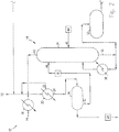
- the SOG is directed to a methanol purification system 10, being diverted from a kiln, boiler, incinerator or other incineration system 12, as shown in Fig. 2 .
- Vapour 14 from the existing stripping column is introduced to a dedicated reflux condenser 16; this vessel may be of any suitable type, such as a falling film type shell and tube evaporator effect.
- the heat from the stripping system may be utilized in the evaporator system, but use of a dedicated vessel allows sufficient control over the system to ensure stable qualities and quantities of SOG are produced under all evaporator operating conditions. Pressure is maintained by throttling the flash vapour from the system.
- SOG is introduced to the methanol purification system 10 at a controlled flow rate, with any excess gas being diverted to the incineration system 12. This helps to maintain the methanol entering the purification system 10 at an optimal content of approximately 40 wt% or less.
- the topping column system 18 strips out low boilers and non-condensables from the SOG, including malodorous sulphur compounds, ammonia, and some ethers, ketones and aldehydes.
- SOG is introduced to the topping reflux condenser 20
- the low boilers and non-condensables are vented 22 back to the incineration system 12 while the condensate is drained 24 to the topping red oils decanter 26.
- Topping red oils pump 28 moves the decanted red oils to a turpentine recovery system (not shown), if available.
- the underflow 32 from the decanter 26 is moved to the topping column 34 by any suitable means, such as topping reflux pump 36.
- a topping reboiler 38 may be used to provide heat to the topping column 34, evaporating the volatile contaminants in a stream 42, which can be returned to the topping reflux condenser 20 or otherwise disposed of.
- Sulphuric acid may be added to topping column 34 by any suitable means, such as feed pump 44.
- the acid is added about the mid-point of the column, or at any rate at an entry point 46 below the input point 48 of the condensed underflow feed from the topping reflux pump 36.
- the separation between the feed input point 48 and the acid entry point 46 allows any highly volatile ammonia present in the underflow feed to be stripped out in the upper section of the topping column 34 before it has a chance to react with the acid, thereby avoiding the formation of ammonium sulphate precipitates.
- the acid reduces the pH in the lower section of the topping column 34, releasing dissociated hydrogen sulphide and methyl mercaptan, which will rise to the upper section of topping column 34, where it can be removed as part of volatile contaminant stream 42.
- the underflow 50 from the topping column 34 flows to the surge tank 52, with some being recycled to topping reboiler 38.
- the surge tank can smooth out the flow and concentration of the feed to the methanol rectification column system 54.
- the feed enters rectification system 54 from surge tank 52, such as by rectification feed pump 56.
- the rectification column system 54 comprises two sections, namely a bottoms stripping section 97 and a top rectification section 99, as shown in Fig. 3 .
- the feed is introduced to the stripping section 97 of column 55 and flows down through the packing, countercurrent to the stripping steam 57, which may be supplied by a rectification reboiler 59.
- the volatile component including methanol, moves upward to the top rectification section 99, while the less volatile component, which is mainly water along with other high boilers, is removed as the underflow 63.
- the feed may also comprise intermediate boilers, such as some higher alcohols (primarily ethanol), higher ketones, etc.
- intermediate boilers such as some higher alcohols (primarily ethanol), higher ketones, etc.
- fusel oils are drawn off from the bottoms column 55, preferably at a point 65 located below the feed introduction point 67.
- the fusel oils can be recovered separately, or may be combined with the underflow 63 from the column 55, passing to effluent treatment through rectification bottoms pump 69.
- the overhead vapour flow 61 comprising methanol and other volatiles, from upper rectification section 99 is condensed in a rectification reflux condenser 71, located above column 55. Any low boilers and non-condensables 73 may be vented to the incineration system 12.
- the remaining product which is approximately 99.85 wt% methanol, is drawn off in a stream 75, preferably located slightly below the top of the packing in top rectification section 99, and moved to a methanol cooler 77 by suitable means such as by methanol pump 79, where it can be moved to storage.
- the methanol product is preferably drawn off in sufficient quantities to maintain the methanol profile in the column.
- the two sections of rectification column system 54 may be supplied in two separate columns, the rectification bottoms column 60 and the rectification top column 62, as shown in Fig. 4 .
- the feed is introduced 64 to the stripping section of the bottoms column 60 and flows down through the packing, countercurrent to the stripping steam 66, which may be supplied by a rectification reboiler 68.
- the volatile component including methanol, is removed into the overhead vapour flow 70, while the less volatile component, which is mainly water along with other high boilers, is removed as the underflow 72.
- the fusel oils are drawn off from the bottoms column 60, preferably at a point 74 located below the feed introduction point 64.
- the fusel oils can be recovered separately, or may be combined with the underflow 72 from the column 60, passing to effluent treatment through rectification bottoms pump 76.
- the overhead vapour flow 70 from rectification bottoms column 60 is directed to the lower section of the rectification top column 62. Any condensate 80 collected in the bottom of the top column 62 may be returned by an intermediate rectification pump 82 to introduction point 84 of the bottoms column 60. Vapour 86 from the top column 62 is condensed in a rectification reflux condenser 88, located above top column 62. Any low boilers and non-condensables 78 may be vented to the incineration system 12.
- the remaining product which is approximately 99.85 wt% methanol, is drawn off in a stream 90, preferably located slightly below the top of the packing in top column 62.
- the methanol product is preferably drawn off in sufficient quantities to maintain the methanol profile in the column and moved to the methanol cooler 94 by suitable means such as by methanol pump 92, where it can be moved to storage.
Claims (16)
- Verfahren zum Wiedergewinnen und Reinigen von Methanol aus einem gestrippten Gasstrom, aufweisend die folgenden Schritte:Erhalten eines Abgas-Speisestroms (14) mit einer gesteuerten Rate, der nicht mehr als ungefähr 40 Gew.-% Methanol enthält;Kondensieren (20) des Abgas-Speisestroms;Dekantieren (26) unvermischbarer Verunreinigungsstoffe aus dem kondensierten Abgas-Speisestrom;Destillieren (34) des kondensierten Abgas-Speisestroms in der Anwesenheit einer Säure zum Verdampfen flüchtiger Komponenten (42), wodurch ein verunreinigter Methanol-Speisestrom (52) verbleibt, wobei die Säure an einem Eingangspunkt (46) unterhalb eines Einleitungspunkts (48) des kondensierten Abgas-Speisestroms zugeführt wird;Raffinieren (97, 60) des verunreinigten Methanol-Speisestroms durch Erwärmen (59, 68) zum Verdampfen von Methanol aus dem verunreinigten Methanol-Speisestrom und Entfernen von Verunreinigungen als ein Unterlauf (63, 65, 72, 74); undweiteres Raffinieren (99, 62) des verdampften Methanols durch Entfernen von Verunreinigungen als ein über Kopf abgehender Dampffluss (73, 78) zum Erzeugen gereinigten Methanols (75, 90).
- Verfahren gemäß Anspruch 1, ferner aufweisend den Schritt des Ableitens einer überschüssigen Menge des Abgas-Speisestroms an ein Entsorgungssystem vor dem Schritt des Kondensierens.
- Verfahren gemäß Anspruch 1, ferner aufweisend die Schritte des Kühlens und Sammelns des verdampften Methanols.
- Verfahren gemäß Anspruch 1, ferner aufweisend den Schritt des Strippens von Fuselölen aus dem verunreinigten Methanol-Speisestrom während des Schritts des Raffinierens.
- Verfahren gemäß Anspruch 1, ferner aufweisend den Schritt des Speicherns des verunreinigten Methanol-Speisestroms vor dem Schritt des Raffinierens des verunreinigten Methanol-Speisestroms.
- Verfahren gemäß Anspruch 1, ferner aufweisend den Schritt des Rückführens des Unterlaufs zu dem Schritt des Raffinierens des verunreinigten Methanol-Speisestroms.
- Vorrichtung zum Durchführen des Verfahrens gemäß Anspruch 1 zum Wiedergewinnen und Reinigen von Methanol aus einem gestrippten Gasstrom (14),
aufweisend:ein Kondensiermittel (20) zum Erhalten und Kondensieren einer gesteuerten Menge eines gestrippten Gases (14), das nicht mehr als ungefähr 40 Gew.-% Methanol enthält;ein Dekantiermittel (26) zum Entfernen unvermischbarer Verunreinigungsstoffe aus dem kondensierten Gas;ein erstes Destilliermittel (34), das einen unteren und einen oberen Abschnitt aufweist, zum Aufnehmen des kondensierten Gases an einem Einleitungspunkt (48) in dem oberen Abschnitt, und zum Erwärmen des kondensierten Gases in der Anwesenheit einer an einem Eingangspunkt (46) in dem unteren Abschnitt aufgenommenen Säure zum Verdampfen flüchtiger Komponenten, wodurch verunreinigtes Methanol verbleibt;einen ersten Raffinierungsabschnitt (97, 60) zum Verdampfen von Methanol aus dem verunreinigten Methanol und Entfernen von Verunreinigungen als ein Unterlauf; undeinen zweiten Raffinierungsabschnitt (99, 62) zum Entfernen von Verunreinigungen aus dem verdampften Methanol als ein über Kopf abgehender Dampffluss (61, 70), wodurch gereinigtes Methanol erzeugt wird. - Vorrichtung gemäß Anspruch 7, ferner aufweisend ein Speichermittel (52) zum Speichern des verunreinigten Methanols vor der Einspeisung in den ersten Raffinierungsabschnitt (54).
- Vorrichtung gemäß Anspruch 7, ferner aufweisend ein Mittel zum Auffangen (75, 90) und Kondensieren (77, 94) des gereinigten Methanols zur Speicherung.
- Vorrichtung gemäß Anspruch 7, ferner aufweisend ein Mittel (65, 74) zum Entfernen von Fuselölen aus dem verunreinigten Methanol.
- Vorrichtung gemäß Anspruch 7, wobei das erste Destillationsmittel (34) eine Topp-Säule beinhaltet.
- Vorrichtung gemäß Anspruch 11, wobei die Topp-Säule ferner einen Verdampfungsofen (38) zum Rückgewinnen eines Teils des verunreinigten Methanols aufweist.
- Vorrichtung gemäß Anspruch 7, wobei mindestens ein Abschnitt aus dem ersten Raffinierabschnitt (97, 60) und dem zweiten Raffinierabschnitt (99, 62) ein zweites Destilliermittel beinhaltet.
- Vorrichtung gemäß Anspruch 13, wobei das zweite Destillationsmittel eine Rektifiziersäule beinhaltet.
- Vorrichtung gemäß Anspruch 13, wobei das zweite Destillationsmittel eine erste und eine zweite Rektifiziersäule (60, 62) beinhaltet.
- Vorrichtung gemäß Anspruch 7, ferner aufweisend ein Mittel zum Ableiten überschüssigen Gases an ein Entsorgungssystem (12) vor der Einspeisung in das Kondensiermittel (20).
Priority Applications (2)
| Application Number | Priority Date | Filing Date | Title |
|---|---|---|---|
| PT09839848T PT2396105T (pt) | 2009-02-12 | 2009-02-12 | Processo e dispositivo de purificação de metanol |
| PL09839848T PL2396105T3 (pl) | 2009-02-12 | 2009-02-12 | Sposób i urządzenie do oczyszczania metanolu |
Applications Claiming Priority (1)
| Application Number | Priority Date | Filing Date | Title |
|---|---|---|---|
| PCT/CA2009/000172 WO2010091492A1 (en) | 2009-02-12 | 2009-02-12 | Methanol purification method and apparatus |
Publications (3)
| Publication Number | Publication Date |
|---|---|
| EP2396105A1 EP2396105A1 (de) | 2011-12-21 |
| EP2396105A4 EP2396105A4 (de) | 2015-07-01 |
| EP2396105B1 true EP2396105B1 (de) | 2018-08-22 |
Family
ID=42561342
Family Applications (1)
| Application Number | Title | Priority Date | Filing Date |
|---|---|---|---|
| EP09839848.0A Active EP2396105B1 (de) | 2009-02-12 | 2009-02-12 | Methanolreinigungsverfahren und -vorrichtung |
Country Status (16)
| Country | Link |
|---|---|
| US (2) | US9320986B2 (de) |
| EP (1) | EP2396105B1 (de) |
| JP (1) | JP5895537B2 (de) |
| KR (1) | KR101667829B1 (de) |
| CN (1) | CN102316961B (de) |
| AU (1) | AU2009339923B2 (de) |
| BR (1) | BRPI0924466B1 (de) |
| CA (1) | CA2751602C (de) |
| EA (1) | EA020038B1 (de) |
| ES (1) | ES2698367T3 (de) |
| MX (1) | MX2011008516A (de) |
| NZ (1) | NZ594625A (de) |
| PL (1) | PL2396105T3 (de) |
| PT (1) | PT2396105T (de) |
| WO (1) | WO2010091492A1 (de) |
| ZA (1) | ZA201106420B (de) |
Families Citing this family (18)
| Publication number | Priority date | Publication date | Assignee | Title |
|---|---|---|---|---|
| JP5895537B2 (ja) | 2009-02-12 | 2016-03-30 | エー.エイチ ランドバーグ システムズ リミテッド | メタノールの精製方法および装置 |
| FI127304B (fi) * | 2011-02-03 | 2018-03-15 | Stora Enso Oyj | Menetelmä puhdistetun metanolin valmistamiseksi sulfaattisellukeiton lauhteesta |
| RU2496558C1 (ru) * | 2012-03-29 | 2013-10-27 | Андрей Юрьевич Беляев | Способ регенерации метанола из насыщенного водой раствора |
| RU2493902C1 (ru) * | 2012-03-29 | 2013-09-27 | Общество с ограниченной ответственностью "ПРОТЭК" | Блок регенерации метанола из насыщенного водой раствора |
| CN102839056B (zh) * | 2012-09-18 | 2014-05-14 | 中国科学院广州能源研究所 | 生物柴油甲醇阶梯式回收提纯方法与装置 |
| DE102013207282A1 (de) * | 2013-04-22 | 2014-11-06 | Wacker Chemie Ag | Verfahren und Vorrichtung zur destillativen Trennung eines Drei- oder Mehrkomponentengemisches |
| US9394220B2 (en) | 2013-06-19 | 2016-07-19 | Fpinnovations | Method for producing bio-methanol at pulp mills |
| PT3055280T (pt) | 2013-10-11 | 2019-06-28 | Andritz Oy | Processo de remoção de enxofre de metanol em bruto |
| DE102015102627A1 (de) | 2015-02-24 | 2016-08-25 | L'Air Liquide, Société Anonyme pour l'Etude et l'Exploitation des Procédés Georges Claude | Anlage und Verfahren zur Herstellung von aufgereinigtem Methanol |
| CN108409535B (zh) * | 2017-09-15 | 2024-01-30 | 江苏九天高科技股份有限公司 | 一种杂醇油的回用方法、煤制甲醇的生产工艺以及装置 |
| SE1850706A1 (en) * | 2018-06-11 | 2019-12-12 | Valmet Oy | A method and a system for obtaining methanol from foul condensate of a pulping process |
| CN113557220B (zh) | 2019-03-07 | 2023-10-27 | 沙特基础工业全球技术公司 | 循环杂醇油以制备甲醇的系统和方法 |
| SE2130226A1 (en) * | 2019-03-18 | 2021-08-24 | Noram Eng And Constructors Ltd | Kraft pulping foul condensate treatment process and apparatus |
| KR102357192B1 (ko) * | 2019-08-28 | 2022-02-07 | 한국과학기술원 | 복합 열교환형 다성분 공비 혼합물의 분별증류장치 및 이를 이용한 분별증류방법 |
| RU2728272C1 (ru) * | 2019-12-12 | 2020-07-28 | Игорь Борисович Мерзляков | Установка регенерации метанола |
| SE544418C2 (en) * | 2020-09-22 | 2022-05-17 | Mill Solution And Tech Ab | Method for separation of reduced nitrogen and reduced sulphur from a feed of foul methanol vapor |
| CN113087597B (zh) * | 2021-03-22 | 2022-11-25 | 国家能源集团宁夏煤业有限责任公司 | 甲醇精馏的方法和甲醇精馏系统 |
| CN113548329B (zh) * | 2021-07-22 | 2023-03-24 | 广船国际有限公司 | 甲醇燃料围护系统及船舶 |
Family Cites Families (13)
| Publication number | Priority date | Publication date | Assignee | Title |
|---|---|---|---|---|
| SE365008B (de) | 1971-11-19 | 1974-03-11 | Mo Och Domsjoe Ab | |
| FI52367C (fi) | 1976-04-20 | 1977-08-10 | Rosenlew Ab Oy W | Menetelmä sellutuksessa syntyvien rikkiyhdisteiden, helposti haihtuvie n alkoholien ja tärpätin tai sen tapaisten talteenottamiseksi |
| FI52710C (fi) * | 1976-04-22 | 1977-11-10 | Kemi Oy | Menetelmä sulfaattiprosessin lauhteista erotetun metanolin puhdistamis eksi. |
| CN1020411C (zh) * | 1990-12-03 | 1993-05-05 | 中国石油化工总公司 | 混相催化反应蒸馏工艺及设备 |
| US5450892A (en) * | 1993-03-29 | 1995-09-19 | Alliedsignal Inc. | Alkaline scrubber for condensate stripper off-gases |
| SE503351C2 (sv) | 1994-09-06 | 1996-05-28 | Ahlstroem Oy | Förfarande för rening av sekundära kondensat vid indunstning av avlutar |
| SE503793C2 (sv) * | 1995-02-01 | 1996-09-09 | Kvaerner Pulping Tech | Förfarande vid behandling av kondensat |
| US5718810A (en) * | 1996-03-19 | 1998-02-17 | The Dow Chemical Company | Methanol recovery using extractive distillation |
| US6217711B1 (en) * | 1998-02-11 | 2001-04-17 | Andritz-Ahlstrom Oy | Method of treating condensates |
| SE524106C2 (sv) * | 1999-10-13 | 2004-06-29 | Soedra Cell Ab | Reduktion av NOx |
| MY143253A (en) * | 2002-08-01 | 2011-04-15 | Gfe Patent As | Method and device for stripping ammonia from liquids |
| FI120363B (fi) * | 2002-11-20 | 2009-09-30 | Andritz Oy | Menetelmä sellutehtaan typpioksidipäästöjen vähentämiseksi |
| JP5895537B2 (ja) | 2009-02-12 | 2016-03-30 | エー.エイチ ランドバーグ システムズ リミテッド | メタノールの精製方法および装置 |
-
2009
- 2009-02-12 JP JP2011549400A patent/JP5895537B2/ja active Active
- 2009-02-12 PL PL09839848T patent/PL2396105T3/pl unknown
- 2009-02-12 PT PT09839848T patent/PT2396105T/pt unknown
- 2009-02-12 MX MX2011008516A patent/MX2011008516A/es active IP Right Grant
- 2009-02-12 ES ES09839848T patent/ES2698367T3/es active Active
- 2009-02-12 AU AU2009339923A patent/AU2009339923B2/en active Active
- 2009-02-12 CN CN200980156693.0A patent/CN102316961B/zh active Active
- 2009-02-12 NZ NZ594625A patent/NZ594625A/xx unknown
- 2009-02-12 US US13/201,206 patent/US9320986B2/en active Active
- 2009-02-12 BR BRPI0924466-2A patent/BRPI0924466B1/pt active IP Right Grant
- 2009-02-12 KR KR1020117019700A patent/KR101667829B1/ko active IP Right Grant
- 2009-02-12 EP EP09839848.0A patent/EP2396105B1/de active Active
- 2009-02-12 CA CA2751602A patent/CA2751602C/en active Active
- 2009-02-12 WO PCT/CA2009/000172 patent/WO2010091492A1/en active Application Filing
- 2009-02-12 EA EA201171029A patent/EA020038B1/ru not_active IP Right Cessation
-
2011
- 2011-09-01 ZA ZA2011/06420A patent/ZA201106420B/en unknown
-
2016
- 2016-03-22 US US15/077,427 patent/US9938216B2/en active Active
Non-Patent Citations (1)
| Title |
|---|
| None * |
Also Published As
| Publication number | Publication date |
|---|---|
| EA201171029A1 (ru) | 2012-01-30 |
| CA2751602C (en) | 2015-05-26 |
| BRPI0924466B1 (pt) | 2020-06-30 |
| BRPI0924466A2 (pt) | 2016-02-16 |
| US20160200651A1 (en) | 2016-07-14 |
| KR101667829B1 (ko) | 2016-10-19 |
| PT2396105T (pt) | 2018-11-29 |
| EA020038B1 (ru) | 2014-08-29 |
| EP2396105A4 (de) | 2015-07-01 |
| PL2396105T3 (pl) | 2019-02-28 |
| CN102316961B (zh) | 2014-07-16 |
| KR20110119746A (ko) | 2011-11-02 |
| US9938216B2 (en) | 2018-04-10 |
| JP2012517451A (ja) | 2012-08-02 |
| AU2009339923A1 (en) | 2011-09-08 |
| CN102316961A (zh) | 2012-01-11 |
| ZA201106420B (en) | 2012-08-29 |
| CA2751602A1 (en) | 2010-08-19 |
| AU2009339923B2 (en) | 2014-04-24 |
| ES2698367T3 (es) | 2019-02-04 |
| JP5895537B2 (ja) | 2016-03-30 |
| US9320986B2 (en) | 2016-04-26 |
| NZ594625A (en) | 2013-06-28 |
| US20110306807A1 (en) | 2011-12-15 |
| MX2011008516A (es) | 2011-10-11 |
| WO2010091492A1 (en) | 2010-08-19 |
| EP2396105A1 (de) | 2011-12-21 |
Similar Documents
| Publication | Publication Date | Title |
|---|---|---|
| EP2396105B1 (de) | Methanolreinigungsverfahren und -vorrichtung | |
| CN105324357B (zh) | 用于在纸浆厂生产生物甲醇的方法 | |
| EP2630292B1 (de) | Verfahren und anordnung zur entfernung von verunreinigungen aus flüssigkeiten oder gasen | |
| US11898309B2 (en) | Method and a system for obtaining methanol from foul condensate of a pulping process | |
| UA60381C2 (uk) | Спосіб одержання моноетиленгліколю високої чистоти | |
| RU2235710C2 (ru) | Способ получения высокочистого моноэтиленгликоля | |
| US4915784A (en) | Process and apparatus for removing contaminants from pulp digester vent gas | |
| Olsson et al. | Simulation of the condensate treatment process in a kraft pulp mill | |
| Lin et al. | The basics of foul condensate stripping | |
| US3323289A (en) | Method of removing neutral malodorous impurities formed in sulfate pulping | |
| SE2051099A1 (en) | Method for separation of reduced nitrogen and reduced sulphur from a feed of foul methanol vapor | |
| SE451334B (sv) | Sett och anordning for minskning av lukt och reducering av processvavelutslepp fran sulfatmassaprocesser | |
| MXPA01002968A (en) | Method for producing highly pure monoethylene glycol | |
| MXPA01002578A (en) | Method for producing highly pure monoethylene glycol |
Legal Events
| Date | Code | Title | Description |
|---|---|---|---|
| PUAI | Public reference made under article 153(3) epc to a published international application that has entered the european phase |
Free format text: ORIGINAL CODE: 0009012 |
|
| 17P | Request for examination filed |
Effective date: 20110818 |
|
| AK | Designated contracting states |
Kind code of ref document: A1 Designated state(s): AT BE BG CH CY CZ DE DK EE ES FI FR GB GR HR HU IE IS IT LI LT LU LV MC MK MT NL NO PL PT RO SE SI SK TR |
|
| AX | Request for extension of the european patent |
Extension state: BA RS |
|
| RAX | Requested extension states of the european patent have changed |
Extension state: RS Payment date: 20110818 Extension state: BA Payment date: 20110818 |
|
| RA4 | Supplementary search report drawn up and despatched (corrected) |
Effective date: 20150601 |
|
| RIC1 | Information provided on ipc code assigned before grant |
Ipc: B01D 5/00 20060101ALI20150526BHEP Ipc: B01D 53/72 20060101AFI20150526BHEP Ipc: B01D 3/14 20060101ALI20150526BHEP Ipc: B01D 3/00 20060101ALI20150526BHEP Ipc: D21C 11/06 20060101ALI20150526BHEP |
|
| STAA | Information on the status of an ep patent application or granted ep patent |
Free format text: STATUS: EXAMINATION IS IN PROGRESS |
|
| 17Q | First examination report despatched |
Effective date: 20170913 |
|
| GRAP | Despatch of communication of intention to grant a patent |
Free format text: ORIGINAL CODE: EPIDOSNIGR1 |
|
| STAA | Information on the status of an ep patent application or granted ep patent |
Free format text: STATUS: GRANT OF PATENT IS INTENDED |
|
| INTG | Intention to grant announced |
Effective date: 20180308 |
|
| GRAS | Grant fee paid |
Free format text: ORIGINAL CODE: EPIDOSNIGR3 |
|
| GRAA | (expected) grant |
Free format text: ORIGINAL CODE: 0009210 |
|
| STAA | Information on the status of an ep patent application or granted ep patent |
Free format text: STATUS: THE PATENT HAS BEEN GRANTED |
|
| AK | Designated contracting states |
Kind code of ref document: B1 Designated state(s): AT BE BG CH CY CZ DE DK EE ES FI FR GB GR HR HU IE IS IT LI LT LU LV MC MK MT NL NO PL PT RO SE SI SK TR |
|
| AX | Request for extension of the european patent |
Extension state: BA RS |
|
| RAP1 | Party data changed (applicant data changed or rights of an application transferred) |
Owner name: A.H. LUNDBERG SYSTEMS LIMITED |
|
| REG | Reference to a national code |
Ref country code: GB Ref legal event code: FG4D |
|
| REG | Reference to a national code |
Ref country code: CH Ref legal event code: EP |
|
| REG | Reference to a national code |
Ref country code: AT Ref legal event code: REF Ref document number: 1031812 Country of ref document: AT Kind code of ref document: T Effective date: 20180915 |
|
| REG | Reference to a national code |
Ref country code: IE Ref legal event code: FG4D |
|
| REG | Reference to a national code |
Ref country code: DE Ref legal event code: R096 Ref document number: 602009054087 Country of ref document: DE |
|
| REG | Reference to a national code |
Ref country code: SE Ref legal event code: TRGR |
|
| REG | Reference to a national code |
Ref country code: PT Ref legal event code: SC4A Ref document number: 2396105 Country of ref document: PT Date of ref document: 20181129 Kind code of ref document: T Free format text: AVAILABILITY OF NATIONAL TRANSLATION Effective date: 20181121 |
|
| REG | Reference to a national code |
Ref country code: NO Ref legal event code: T2 Effective date: 20180822 |
|
| REG | Reference to a national code |
Ref country code: NL Ref legal event code: MP Effective date: 20180822 |
|
| REG | Reference to a national code |
Ref country code: LT Ref legal event code: MG4D |
|
| PG25 | Lapsed in a contracting state [announced via postgrant information from national office to epo] |
Ref country code: BG Free format text: LAPSE BECAUSE OF FAILURE TO SUBMIT A TRANSLATION OF THE DESCRIPTION OR TO PAY THE FEE WITHIN THE PRESCRIBED TIME-LIMIT Effective date: 20181122 Ref country code: IS Free format text: LAPSE BECAUSE OF FAILURE TO SUBMIT A TRANSLATION OF THE DESCRIPTION OR TO PAY THE FEE WITHIN THE PRESCRIBED TIME-LIMIT Effective date: 20181222 Ref country code: NL Free format text: LAPSE BECAUSE OF FAILURE TO SUBMIT A TRANSLATION OF THE DESCRIPTION OR TO PAY THE FEE WITHIN THE PRESCRIBED TIME-LIMIT Effective date: 20180822 Ref country code: LT Free format text: LAPSE BECAUSE OF FAILURE TO SUBMIT A TRANSLATION OF THE DESCRIPTION OR TO PAY THE FEE WITHIN THE PRESCRIBED TIME-LIMIT Effective date: 20180822 Ref country code: GR Free format text: LAPSE BECAUSE OF FAILURE TO SUBMIT A TRANSLATION OF THE DESCRIPTION OR TO PAY THE FEE WITHIN THE PRESCRIBED TIME-LIMIT Effective date: 20181123 |
|
| REG | Reference to a national code |
Ref country code: ES Ref legal event code: FG2A Ref document number: 2698367 Country of ref document: ES Kind code of ref document: T3 Effective date: 20190204 Ref country code: SK Ref legal event code: T3 Ref document number: E 28831 Country of ref document: SK |
|
| PG25 | Lapsed in a contracting state [announced via postgrant information from national office to epo] |
Ref country code: HR Free format text: LAPSE BECAUSE OF FAILURE TO SUBMIT A TRANSLATION OF THE DESCRIPTION OR TO PAY THE FEE WITHIN THE PRESCRIBED TIME-LIMIT Effective date: 20180822 Ref country code: LV Free format text: LAPSE BECAUSE OF FAILURE TO SUBMIT A TRANSLATION OF THE DESCRIPTION OR TO PAY THE FEE WITHIN THE PRESCRIBED TIME-LIMIT Effective date: 20180822 |
|
| PG25 | Lapsed in a contracting state [announced via postgrant information from national office to epo] |
Ref country code: IT Free format text: LAPSE BECAUSE OF FAILURE TO SUBMIT A TRANSLATION OF THE DESCRIPTION OR TO PAY THE FEE WITHIN THE PRESCRIBED TIME-LIMIT Effective date: 20180822 Ref country code: RO Free format text: LAPSE BECAUSE OF FAILURE TO SUBMIT A TRANSLATION OF THE DESCRIPTION OR TO PAY THE FEE WITHIN THE PRESCRIBED TIME-LIMIT Effective date: 20180822 Ref country code: EE Free format text: LAPSE BECAUSE OF FAILURE TO SUBMIT A TRANSLATION OF THE DESCRIPTION OR TO PAY THE FEE WITHIN THE PRESCRIBED TIME-LIMIT Effective date: 20180822 |
|
| REG | Reference to a national code |
Ref country code: DE Ref legal event code: R097 Ref document number: 602009054087 Country of ref document: DE |
|
| PG25 | Lapsed in a contracting state [announced via postgrant information from national office to epo] |
Ref country code: DK Free format text: LAPSE BECAUSE OF FAILURE TO SUBMIT A TRANSLATION OF THE DESCRIPTION OR TO PAY THE FEE WITHIN THE PRESCRIBED TIME-LIMIT Effective date: 20180822 |
|
| PLBE | No opposition filed within time limit |
Free format text: ORIGINAL CODE: 0009261 |
|
| STAA | Information on the status of an ep patent application or granted ep patent |
Free format text: STATUS: NO OPPOSITION FILED WITHIN TIME LIMIT |
|
| 26N | No opposition filed |
Effective date: 20190523 |
|
| PG25 | Lapsed in a contracting state [announced via postgrant information from national office to epo] |
Ref country code: SI Free format text: LAPSE BECAUSE OF FAILURE TO SUBMIT A TRANSLATION OF THE DESCRIPTION OR TO PAY THE FEE WITHIN THE PRESCRIBED TIME-LIMIT Effective date: 20180822 |
|
| REG | Reference to a national code |
Ref country code: CH Ref legal event code: PL |
|
| GBPC | Gb: european patent ceased through non-payment of renewal fee |
Effective date: 20190212 |
|
| PG25 | Lapsed in a contracting state [announced via postgrant information from national office to epo] |
Ref country code: MC Free format text: LAPSE BECAUSE OF FAILURE TO SUBMIT A TRANSLATION OF THE DESCRIPTION OR TO PAY THE FEE WITHIN THE PRESCRIBED TIME-LIMIT Effective date: 20180822 Ref country code: LU Free format text: LAPSE BECAUSE OF NON-PAYMENT OF DUE FEES Effective date: 20190212 |
|
| REG | Reference to a national code |
Ref country code: IE Ref legal event code: MM4A |
|
| PG25 | Lapsed in a contracting state [announced via postgrant information from national office to epo] |
Ref country code: CH Free format text: LAPSE BECAUSE OF NON-PAYMENT OF DUE FEES Effective date: 20190228 Ref country code: LI Free format text: LAPSE BECAUSE OF NON-PAYMENT OF DUE FEES Effective date: 20190228 |
|
| PG25 | Lapsed in a contracting state [announced via postgrant information from national office to epo] |
Ref country code: IE Free format text: LAPSE BECAUSE OF NON-PAYMENT OF DUE FEES Effective date: 20190212 Ref country code: GB Free format text: LAPSE BECAUSE OF NON-PAYMENT OF DUE FEES Effective date: 20190212 |
|
| PG25 | Lapsed in a contracting state [announced via postgrant information from national office to epo] |
Ref country code: TR Free format text: LAPSE BECAUSE OF FAILURE TO SUBMIT A TRANSLATION OF THE DESCRIPTION OR TO PAY THE FEE WITHIN THE PRESCRIBED TIME-LIMIT Effective date: 20180822 |
|
| PG25 | Lapsed in a contracting state [announced via postgrant information from national office to epo] |
Ref country code: MT Free format text: LAPSE BECAUSE OF NON-PAYMENT OF DUE FEES Effective date: 20190212 |
|
| PG25 | Lapsed in a contracting state [announced via postgrant information from national office to epo] |
Ref country code: CY Free format text: LAPSE BECAUSE OF FAILURE TO SUBMIT A TRANSLATION OF THE DESCRIPTION OR TO PAY THE FEE WITHIN THE PRESCRIBED TIME-LIMIT Effective date: 20180822 |
|
| REG | Reference to a national code |
Ref country code: AT Ref legal event code: UEP Ref document number: 1031812 Country of ref document: AT Kind code of ref document: T Effective date: 20180822 |
|
| PG25 | Lapsed in a contracting state [announced via postgrant information from national office to epo] |
Ref country code: HU Free format text: LAPSE BECAUSE OF FAILURE TO SUBMIT A TRANSLATION OF THE DESCRIPTION OR TO PAY THE FEE WITHIN THE PRESCRIBED TIME-LIMIT; INVALID AB INITIO Effective date: 20090212 |
|
| PG25 | Lapsed in a contracting state [announced via postgrant information from national office to epo] |
Ref country code: MK Free format text: LAPSE BECAUSE OF FAILURE TO SUBMIT A TRANSLATION OF THE DESCRIPTION OR TO PAY THE FEE WITHIN THE PRESCRIBED TIME-LIMIT Effective date: 20180822 |
|
| PGFP | Annual fee paid to national office [announced via postgrant information from national office to epo] |
Ref country code: NO Payment date: 20230217 Year of fee payment: 15 Ref country code: FR Payment date: 20230217 Year of fee payment: 15 Ref country code: FI Payment date: 20230222 Year of fee payment: 15 Ref country code: ES Payment date: 20230317 Year of fee payment: 15 Ref country code: CZ Payment date: 20230130 Year of fee payment: 15 Ref country code: AT Payment date: 20230215 Year of fee payment: 15 |
|
| PGFP | Annual fee paid to national office [announced via postgrant information from national office to epo] |
Ref country code: SE Payment date: 20230220 Year of fee payment: 15 Ref country code: PL Payment date: 20230130 Year of fee payment: 15 Ref country code: BE Payment date: 20230220 Year of fee payment: 15 |
|
| PGFP | Annual fee paid to national office [announced via postgrant information from national office to epo] |
Ref country code: ES Payment date: 20240301 Year of fee payment: 16 |
|
| PGFP | Annual fee paid to national office [announced via postgrant information from national office to epo] |
Ref country code: AT Payment date: 20240119 Year of fee payment: 16 |
|
| PGFP | Annual fee paid to national office [announced via postgrant information from national office to epo] |
Ref country code: FI Payment date: 20240226 Year of fee payment: 16 Ref country code: DE Payment date: 20240228 Year of fee payment: 16 Ref country code: CZ Payment date: 20240123 Year of fee payment: 16 Ref country code: PT Payment date: 20240118 Year of fee payment: 16 Ref country code: SK Payment date: 20240118 Year of fee payment: 16 |