EP2394881B1 - Tilting bed base and secondary suspension comprising same - Google Patents
Tilting bed base and secondary suspension comprising same Download PDFInfo
- Publication number
- EP2394881B1 EP2394881B1 EP11167944.5A EP11167944A EP2394881B1 EP 2394881 B1 EP2394881 B1 EP 2394881B1 EP 11167944 A EP11167944 A EP 11167944A EP 2394881 B1 EP2394881 B1 EP 2394881B1
- Authority
- EP
- European Patent Office
- Prior art keywords
- bed base
- central pivot
- base according
- vertical
- horizontal
- Prior art date
- Legal status (The legal status is an assumption and is not a legal conclusion. Google has not performed a legal analysis and makes no representation as to the accuracy of the status listed.)
- Not-in-force
Links
Images


Classifications
-
- B—PERFORMING OPERATIONS; TRANSPORTING
- B61—RAILWAYS
- B61F—RAIL VEHICLE SUSPENSIONS, e.g. UNDERFRAMES, BOGIES OR ARRANGEMENTS OF WHEEL AXLES; RAIL VEHICLES FOR USE ON TRACKS OF DIFFERENT WIDTH; PREVENTING DERAILING OF RAIL VEHICLES; WHEEL GUARDS, OBSTRUCTION REMOVERS OR THE LIKE FOR RAIL VEHICLES
- B61F5/00—Constructional details of bogies; Connections between bogies and vehicle underframes; Arrangements or devices for adjusting or allowing self-adjustment of wheel axles or bogies when rounding curves
- B61F5/02—Arrangements permitting limited transverse relative movements between vehicle underframe or bolster and bogie; Connections between underframes and bogies
- B61F5/14—Side bearings
- B61F5/142—Side bearings made of rubber elements, graphite or the like
-
- B—PERFORMING OPERATIONS; TRANSPORTING
- B61—RAILWAYS
- B61F—RAIL VEHICLE SUSPENSIONS, e.g. UNDERFRAMES, BOGIES OR ARRANGEMENTS OF WHEEL AXLES; RAIL VEHICLES FOR USE ON TRACKS OF DIFFERENT WIDTH; PREVENTING DERAILING OF RAIL VEHICLES; WHEEL GUARDS, OBSTRUCTION REMOVERS OR THE LIKE FOR RAIL VEHICLES
- B61F5/00—Constructional details of bogies; Connections between bogies and vehicle underframes; Arrangements or devices for adjusting or allowing self-adjustment of wheel axles or bogies when rounding curves
- B61F5/02—Arrangements permitting limited transverse relative movements between vehicle underframe or bolster and bogie; Connections between underframes and bogies
- B61F5/04—Bolster supports or mountings
- B61F5/06—Bolster supports or mountings incorporating metal springs
-
- B—PERFORMING OPERATIONS; TRANSPORTING
- B61—RAILWAYS
- B61F—RAIL VEHICLE SUSPENSIONS, e.g. UNDERFRAMES, BOGIES OR ARRANGEMENTS OF WHEEL AXLES; RAIL VEHICLES FOR USE ON TRACKS OF DIFFERENT WIDTH; PREVENTING DERAILING OF RAIL VEHICLES; WHEEL GUARDS, OBSTRUCTION REMOVERS OR THE LIKE FOR RAIL VEHICLES
- B61F5/00—Constructional details of bogies; Connections between bogies and vehicle underframes; Arrangements or devices for adjusting or allowing self-adjustment of wheel axles or bogies when rounding curves
- B61F5/02—Arrangements permitting limited transverse relative movements between vehicle underframe or bolster and bogie; Connections between underframes and bogies
- B61F5/04—Bolster supports or mountings
- B61F5/08—Bolster supports or mountings incorporating rubber springs
Definitions
- the subject of the present invention is a rocking bed base and a secondary suspension comprising it, according to the preamble of independent claim 1, which is generally known in the art.
- Bed springs are already known which are used in secondary suspensions of railway vehicles such as wagons, railcars or locomotives to ensure the suspension of the vehicle body with respect to a chassis on which axle-wheel assemblies are mounted by the vehicle. intermediate of a primary suspension.
- a bogie comprising for example two axles and four wheels (or with three axles for example)
- two or four subsets of secondary suspension each of which has a single bed base or a pair of bed bases to obtain a horizontal softening, and one or more metal springs arranged (s) in series with the bed frame or between the bed bases and whose function is to obtain the desired vertical flexibility for the secondary suspension.
- the patent application EP 155 209 A1 relates to an elastic bearing device which consists of a laminated elastomeric ring connected in series with a helical spring to form a secondary suspension of railway bogie.
- an elastic bearing device which consists of a laminated elastomeric ring connected in series with a helical spring to form a secondary suspension of railway bogie.
- This device has only poor tilting properties and therefore poor decoupling of the horizontal stiffness as a function of the direction of horizontal stress.
- the patent FR 1 540 148 A describes a subassembly comprising two helical springs whose upper end is connected to the body of the vehicle and whose lower end is connected to a support pivoting freely around a hinge (or a knife assembly), lateral buffers being provided to serve as an elastic stop for tilting the pivoting support.
- this device has integration and maintenance issues.
- the patent BE 700 027 A describes a vehicle body support member associating a spring with a single hemispherical ball. Implementation a ball joint does not differentiate the characteristics along the directions in the horizontal plane.
- the patent application FR 2 801 268 A1 combines in series a helical spring and two ball joints laminated elastomer or not, mounted head to tail. Such a device imposes in practice a large footprint in the direction of the height to ensure the required performance. In addition, the use of ball joints does not make it possible to differentiate the characteristics according to the horizontal directions.
- the patent application FR 2 354 229 A1 proposes to overcome the metal spring or springs by associating in series a frustoconical spring having a high axial flexibility to ensure vertical deflections of the suspension, and a low horizontal flexibility to provide a vertical guide function, and a cylindrical spring having a high vertical stiffness to support the weight of the body and high horizontal flexibility to accommodate the relative horizontal movements of the body and the bogie.
- This device also does not differentiate the features in the horizontal directions.
- the laminated frustoconical spring can be problematic to ensure high vertical deflections and to ensure a vertical stiffness independent of the load level (the characteristic axial force / axial displacement tends to be nonlinear for this kind of part), this to what is added the problem of creep and thus of rigging to ensure the height of the floor relative to the platform over time.
- the present invention proposes a tilting bed base that can be integrated with a suspension subassembly, in particular a secondary vehicle suspension, which has a parallel-type architecture in which the functions are distributed between a central pivot and at least a pair of elastic studs mounted on either side of the central pivot.
- the first horizontal axis is a preferred tilting axis of the bed, for which the pivot and the resilient pads are biased mainly angularly.
- This parallel architecture has the significant advantage of limiting the vertical space, and thus avoid a major drawback of known devices which is to limit the performance of the device due to the constraints of vertical space. Indeed, the constraints of vertical space often require undersizing parts that can not therefore fully meet the specifications, which affects among other things the comfort of passengers.
- the geometry of the central pivot is preferably frustoconical in order to reduce its conical stiffness, and thus reduce its stiffness in tilting (which is not differentiated by the central pivot.
- Said cylindrical or frustoconical elastic element may be at least partly made of elastomer, in particular of laminated elastomer.
- Said elastic pads may be metal cushions, or be at least partly elastomeric, especially laminated elastomer.
- the ratio between the horizontal stiffnesses of the central pivot and of all the blocks may be greater than or equal to 1 and may be for example between 5 and 50, and preferably at least 10.
- the ratio between the vertical stiffness K PA of all the studs and the central pivot AP K may be greater than or equal to 1 and may for example be between 5 and 50, and preferably at least equal to 10.
- the ratio between the horizontal stiffness and the vertical stiffness of the central pivot may be in particular between 1 and 5 and for example between 2 and 5, and / or the ratio between the vertical stiffness and the horizontal stiffness of a stud may be greater or equal to 10 and can be for example between 50 and 500.
- the bed base can be characterized in that the elastic or frustoconical element of the central pivot has at least one pair of cells disposed symmetrically on either side of the central pivot and whose median planes are aligned on a second horizontal axis perpendicular to said first axis.
- the bed base can be characterized in that at least one central pivot has an abutment integral with its inner part and in that this abutment has a flange spaced apart by a functional clearance j of the outer part of said central pivot to limit the displacement in tension of the elastic element of said central pivot.
- the invention also relates to a suspension subassembly, characterized in that it comprises at least one rocking bed as defined above, the second support receives an end of one or more suspension springs.
- the subassembly may be characterized in that it comprises two so-called rocking bases mounted head to tail, or suspension springs being arranged between the second supports of the two bed bases.
- the subassembly may be characterized in that the first bed base comprises a first stop and in that the second bed base comprises a stop device comprising a strap secured by strap supports integral with the first stop and passing around a support. semi-cylindrical formed in an abutment support integral with the second frame.
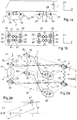
- the Figures 1a and 1b represent a vehicle having a body 1, and two bogies 2 each having two axles 21 and four wheels 22, the axles 21 and the wheels 22 being suspended from the frame 23 of the bogie 2 by a primary suspension 24 comprising four subassemblies 25 .
- the secondary suspension 3 of which each bogie 2 is provided comprises four subassemblies 31 distributed in a quadrilateral.
- the figure 2a shows four subassemblies 31 each having two rocking bases 32 and 33 disposed between one or more metal springs 4 suspension.
- the upper rocking bases 32 are secured to an interface piece 11 with the body 1, and the lower rocking bases 33 are integral with an interface piece 26 with the bogie 2, on which part are also mounted the sub-bases.
- H susp designates the height of the secondary suspension incorporating the bulk of the bed frames 32 and 33.
- the x direction is the longitudinal direction of the vehicle, which is that of its movement in a straight line.
- the direction is the transverse direction of the vehicle, and the direction z, orthogonal to the two previous ones, is the vertical direction.
- the direction u (see also figure 2b ) designates the preferred tilting axis of the rocking bases 32 and 33, and the direction v, the horizontal direction perpendicular to the directions u and z.
- u is the longitudinal direction of the bedsteads, and v is the transverse direction.
- the rocking bed bases have the function of providing a differentiated decoupling, with in particular a privileged tilting around the u-axis and a limited tilting around the v-axis of the mattresses, whereas the metal springs typically provide the obtaining the desired vertical stiffness for the secondary suspension.
- the differentiated decoupling is thus obtained thanks to tilting bed bases that have different stiffness characteristics according to the horizontal directions.
- O1 and O2 are the geometric centers of all upper bed bases 32 and 33, each bed frame 32 having a center A1, B1, C1, D1, and each bed base 33, a center A2, B2, C2, D2.
- O1 is the center of quadrilateral A1, B1, C1, D1 and O2 is the center of quadrilateral A2, B2, C2, D2.
- K x , K y and K ⁇ z respectively denote the longitudinal stiffness of the suspension (x axis), its transverse stiffness (y axis) and its yaw stiffness (body / bogie rotation around the z axis).
- the first horizontal axis u is a preferred tilting axis of the subassembly 31.
- the second horizontal axis v is a limited tilt axis (higher rigidity).
- L, ⁇ are respectively the distance and the angle of implantation of the sub-sets of secondary suspension which are defined by the customer.
- ⁇ is the orientation angle of the local coordinate system ⁇ u, v, z ⁇ with respect to the global coordinate system ⁇ x, y, z ⁇ .
- the orientation of the system is chosen based on the preferred softening direction requested by the customer.
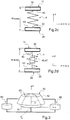
- FIGS. 2c and 2d show a secondary suspension subassembly which comprises a pair of upper and lower tilting basins 33 and one or more suspension metal springs 4 mounted between the bedsteads 32 and 33, with an upper surface 42 and lower 43 assembly of the springs 4.
- a system of high and low stops (46, 47, 48) may be located in the center of the spring or springs 4.
- the pads 60 may be of different technologies: laminated elastomeric type (parallel to the reinforcements) or non-laminated, or metal cushion type to choose.
- the pivot 50 and the pads 60 are arranged in parallel, and they act in parallel both in the vertical direction and in the horizontal directions.
- the stiffnesses are added and is therefore the sum of the radial stiffness K RP of the pivot 50 and the shear stiffness K CP of all the pads 60.
- the radial stiffness K RP of the pivot 50 is much greater than the K CP shear stiffness of the set of pads 60, it is the pivot 50 which takes up most of the horizontal force.
- the stiffnesses are also added, and the stiffness in this direction is the sum of the axial stiffness K AP of the pivot 50 and the axial stiffness K ' AP of the pads 60 taken as a whole (namely the sum stiffness of the pads), and as the axial stiffness K AP of the pivot 50 is very lower than the Axial stiffness K ' AP of the pads 60, it is the pads 60 which take up most of the vertical force.
- This parallel architecture makes it possible to significantly reduce vertical congestion, and consequently to meet the requirements of a specification in a space of reduced height.
- pairs of pads 60 in parallel with the central pivot 50 makes it possible to take up the vertical force (according to z) and to control the conical tilting ⁇ v about the axis v (limited tilting axis) while keeping a constant tilting flexibility in the other directions, including tilting about the u-axis, for which the flexibility tilt is defined primarily by the cylindrical or conical layer of laminated elastomer or not the central pivot.
- the pads 60 are represented as being cylindrical of revolution, but other shapes (polygon, etc %) can be implemented.
- the pivot 50 is shown as having a frustoconical elastic element 53, with a half opening angle ⁇ . It could also be cylindrical of revolution. The value of the opening angle ⁇ can also be between 0 ° and 60 ° and more particularly between 8 ° and 30 °.
- the pivot comprises an internal frame 51 cylindrical or frustoconical, an outer frame 52 cylindrical or frustoconical and an elastic member 53, for example laminated elastomer or not.
- the ratio between the horizontal stiffness of the central pivot 50 (radial stiffness K RP ) and the pads (stiffness in shear K CP ) can be between 5 and 50, and preferably at least equal to 10. A typical value of the order of 20 can be advocated.
- This ratio is defined essentially by the geometry (cylindrical shape of the studs, with opposite reinforcement, cylindrical or frustoconical shape of the pivot with an internal reinforcement and an external reinforcement).
- the ratio between the axial (vertical) stiffnesses of all the pads 60 (K ' AP ) and the central pivot 50 (K AP ) can be between 5 and 50. This ratio is preferably at least equal to 10. typical value of the order of 20 may be recommended.
- the vertical stiffness of the pads 60 is chosen by acting on their geometry, their characteristics (materials) as well as on the manufacturing process (elastomer laminate or not, metal cushions).
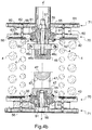
- FIGS. 4a to 4d represent a preferred embodiment of a suspension subassembly comprising two rocking bed bases according to the invention, which are mounted head to tail.
- An upper rocking bed 32 includes a central pivot 50 whose inner armature 51 is integral with a plate 71 which constitutes the interface piece 11 with the body 1 and whose outer armature 52 is integral with a plate 70 of which the lower face is the bearing face 42 of the springs 4 (here two in number).
- the opening of the cone of the elastic element 53 is directed upwards, which favors the proximity or the coincidence of the natural centers of tilting of the pivot and the studs. Disregarding the tilt stiffness induced by the compression component of the pads 60, that is to say in practice by considering the u axis, this particular arrangement of these natural centers makes it possible to obtain a lower resistance to tilting. along the axis u.
- the cylindrical pads 60 each comprise two plates 62 and 63, and a cushion 61 preferably a metal cushion, the whole being arranged between the plates 70 and 71.
- the centering of the cushions 61 is provided by pins 56. They are mounted to be diametrically opposed, with respect to the axis ZZ, and aligned in the direction u.
- On the inner frame 51 is also mounted the low elastic stop 46 and its support 46b through the stud 57 by sandwiching the assembly (50, 60, 61, 62, 63, 70, 71).
- the plates 62 and 63 are chosen from a material of sufficient hardness to withstand the contact pressure of the cushions 61.
- the lower bed base 33 which is mounted head to tail with respect to the frame 32, has a central block 50 whose inner frame 51 is integral with a plate 71, but which constitutes the interface piece 26 with the bogie 2, and whose outer armature 52 is integral with a plate 70 whose upper face is the bearing surface 43 of the springs 4.
- the described architecture for the upper bed base 32 is similar for the lower bed base 33, except that on the inner frame 51 is mounted the lower abutment support 47 via the fixing screw 58 and the opening of the cone is oriented downwards.
- the abutment 46 may come into contact with the support 47 to limit the compression amplitude of the springs 4.
- the lower abutment support 47 can be arranged to integrate the passage 47 1 with a strap (not shown) making it possible to perform the function of a lift limit limiting the amplitude. extension of the secondary suspension subassembly 31 during the lifting of the vehicle and ensuring possible preload of the spring or springs 4.
- the assembly 47 is located below the abutment 46 because, under the effect of gravity, the strap suspended after its two attachments 46c integrated with the abutment 46 is suitably in place vis-à-vis the semi contour -cylindrical 47 2 of passage 47 1 .
- the stop 46 could be permuted with the abutment support 47 and the passage 47 1 .
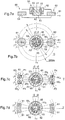
- the number of steps of assembly of a rocking bed base can be optimized during its industrialization by grouping in one piece of the components 51 and 71, as illustrated by the variant of the figure 5 .
- the part 51 ' has a flange 51 "which serves as a plate 71.
- the axial flexibility of the pivot 50 can be used to help the mounting of the pads 60.
- the pins 56 of centering pads 60 can be reported from the outside.
- the interface between the body 1 or the bogie 2 and the supports 70 of the metal springs is integrated at the central pivot.
- the abutment abutment 46b '/ 47' forms a collar 46 "/ 47" which has at its periphery a vertical clearance j with the outer armature 52.
- the functional clearance j is kept under normal operating conditions, in order not to clamp the tilting of the bed base.
- the flange 46 "/ 47” limits to the value of the functional clearance j the displacement in traction of the elastic element 53 of the pivot, which limits the stress in traction of the pivot during the lifting of the body and thus ensures the stop function high intrinsic to the rocking bases 32 and 33.
- FIGS 7a to 7d show three embodiments of the pairs of pads. In each of them, the pads are diametrically opposed with respect to the center A2 located on the axis ZZ '.
- the figure 7a (vertical section) is common to Figures 7b to 7d .
- FIG. 7c there are two pairs of pins 60 1 , 60 2 , and 60 3 , 60 4 respectively , extending on either side of the axis u over an angular sector ⁇ 1.
- Their centers P 1 , P 2 , P 3 , P 4 are situated on a straight line respectively A2P 1 , A2P 2 , A2P 3 , A2P 4 forming with the axis u an angle respectively ⁇ P 1 , ⁇ P 2 , ⁇ P 3 , ⁇ P 4 .
- An even number of pads greater than 4 could also be used.
- the value of the angles ⁇ P 1 , ⁇ P 2 , ⁇ P 3 , ⁇ P 4 is chosen to be identical in order to balance the system.
- the stiffness in compression K ' AP of the pads is greater than or equal to the axial stiffness K AP of the pivot, ie K' AP ⁇ K AP with a ratio advantageously at least equal to 5 and preferably at least equal to 10, and which can for example between 5 and 50.
- K RP ⁇ K CP with a ratio of at least 5 and preferably 10, and which may be for example between 5 and 50.
- the system is symmetrical center A2 to balance the recovery efforts.
- the section of the studs can be of any shape: they are schematized in the examples in the form of cylinders or sectors for simplify the representation. Their section can be optimized taking into account the parameters listed above ( ⁇ 1, D).
- ⁇ 1 is chosen less than 45 ° and preferably between 0 ° and 25 ° and / or ⁇ 2 can be chosen up to 60 ° and preferably between 5 ° and 25 °.
Description
La présente invention a pour objet un sommier basculant et une suspension secondaire le comportant, selon le préambule de la revendication indépendante 1, qui est généralement connu dans l'art. On connaît déjà des sommiers qui sont utilisés dans des suspensions secondaires de véhicules ferroviaires tels que des wagons, des automotrices ou des locomotives pour assurer la suspension de la caisse du véhicule par rapport à un châssis sur lequel sont montés des ensembles essieu-roues par l'intermédiaire d'une suspension primaire.The subject of the present invention is a rocking bed base and a secondary suspension comprising it, according to the preamble of
Pour un bogie comportant par exemple deux essieux et quatre roues (ou bien comportant trois essieux par exemple), il est connu de disposer de deux ou quatre sous-ensembles de suspension secondaire, dont chacun présente un seul sommier ou une paire de sommiers pour obtenir un assouplissement horizontal, et un ou plusieurs ressorts métalliques disposé(s) en série avec le sommier ou entre les sommiers et dont la fonction est d'obtenir la souplesse verticale souhaitée pour la suspension secondaire.For a bogie comprising for example two axles and four wheels (or with three axles for example), it is known to have two or four subsets of secondary suspension, each of which has a single bed base or a pair of bed bases to obtain a horizontal softening, and one or more metal springs arranged (s) in series with the bed frame or between the bed bases and whose function is to obtain the desired vertical flexibility for the secondary suspension.
Il existe plusieurs types de sommiers destinés à de telles applications, mais leurs performances sont limitées.There are several types of bed bases for such applications, but their performance is limited.
La Demande de Brevet
Le Brevet
Le Brevet
La Demande de Brevet
La Demande de Brevet
De plus, le ressort tronconique lamifié peut poser problème pour assurer des débattements verticaux importants et pour garantir une raideur verticale indépendante du niveau de charge (la caractéristique effort axial / déplacement axial a tendance à être non linéaire pour ce genre de pièce), ce à quoi s'ajoute la problématique du fluage et donc de calage pour assurer la hauteur du plancher par rapport au quai au cours du temps.In addition, the laminated frustoconical spring can be problematic to ensure high vertical deflections and to ensure a vertical stiffness independent of the load level (the characteristic axial force / axial displacement tends to be nonlinear for this kind of part), this to what is added the problem of creep and thus of rigging to ensure the height of the floor relative to the platform over time.
Les inventeurs du présent brevet considèrent qu'il serait souhaitable de permettre de différencier les performances de découplage latéral, tout en limitant l'encombrement vertical.The inventors of this patent consider that it would be desirable to make it possible to differentiate the lateral decoupling performance while limiting the vertical space requirement.
A cet effet, la présente invention propose un sommier basculant qui peut être intégré à un sous-ensemble de suspension, notamment de suspension secondaire de véhicule, qui présente une architecture de type parallèle dans laquelle les fonctions sont réparties entre un pivot central et au moins une paire de plots élastiques montés de part et d'autre du pivot central.To this end, the present invention proposes a tilting bed base that can be integrated with a suspension subassembly, in particular a secondary vehicle suspension, which has a parallel-type architecture in which the functions are distributed between a central pivot and at least a pair of elastic studs mounted on either side of the central pivot.
La présente invention concerne ainsi un sommier basculant destiné à une suspension d'un véhicule, notamment un véhicule ferroviaire tel qu'un wagon, une automotrice ou une locomotive, pour assurer, d'une part, une reprise d'une charge verticale générée par la caisse du véhicule, et d'autre part, pour accompagner avec basculement des mouvements relatifs horizontaux, le sommier comportant un premier support pour son montage sur un élément du véhicule et un deuxième support espacé verticalement du premier support, pour recevoir une extrémité d'un ressort de suspension, caractérisé en ce qu'il comporte en parallèle :
- un pivot central de guidage vertical comportant un élément élastique cylindrique ou tronconique monté entre une pièce interne et une pièce externe, la pièce interne étant solidaire de l'un desdits premier et deuxième supports et la pièce externe étant solidaire de l'autre desdits premier et deuxième supports, ledit pivot présentant une raideur horizontale supérieure à sa raideur verticale,
- et disposés symétriquement de part et d'autre du pivot central, au moins une paire de plots élastiques dont les centres sont alignés sur un premier axe horizontal et qui sont montés entre le premier et le deuxième support et présentent une raideur verticale ou de compression élevée par rapport à leur raideur horizontale ou de cisaillement.
- a central vertical guide pivot comprising a cylindrical or frustoconical elastic element mounted between an inner part and an outer part, the inner part being integral with one of said first and second supports and the outer part being integral with the other of said first and second second supports, said pivot having a horizontal stiffness greater than its vertical stiffness,
- and arranged symmetrically on either side of the central pivot, at least one pair of elastic studs whose centers are aligned on a first horizontal axis and which are mounted between the first and the second support and have a vertical stiffness or high compression compared to their horizontal stiffness or shear.
Le premier axe horizontal constitue un axe de basculement privilégié du sommier, pour lequel le pivot et les plots élastiques sont sollicités principalement angulairement.The first horizontal axis is a preferred tilting axis of the bed, for which the pivot and the resilient pads are biased mainly angularly.
La présence d'une ou plusieurs paires de plots disposés de part et d'autre du pivot central permet d'augmenter la raideur en basculement autour d'un deuxième axe horizontal perpendiculaire au dit premier axe, car à la raideur de basculement précédente s'ajoute celle induite par la compression des plots élastiques.The presence of one or more pairs of studs disposed on either side of the central pivot makes it possible to increase the tilt stiffness around a second horizontal axis perpendicular to said first axis, because at the previous tilting stiffness s' adds the one induced by the compression of the elastic studs.
Cette architecture en parallèle présente l'avantage notable de limiter l'encombrement vertical, et d'éviter ainsi un inconvénient majeur des dispositifs connus qui est de limiter les performances du dispositif en raison des contraintes d'encombrement vertical. En effet, les contraintes d'encombrement vertical obligent fréquemment à un sous-dimensionnement des pièces qui ne peuvent en conséquence pas répondre pleinement au cahier des charges, ce qui affecte entre autres le confort des passagers.This parallel architecture has the significant advantage of limiting the vertical space, and thus avoid a major drawback of known devices which is to limit the performance of the device due to the constraints of vertical space. Indeed, the constraints of vertical space often require undersizing parts that can not therefore fully meet the specifications, which affects among other things the comfort of passengers.
La géométrie du pivot central est de préférence tronconique afin de réduire sa raideur en conique, et donc de réduire sa raideur en basculement (qui n'est pas différenciée par le pivot central.The geometry of the central pivot is preferably frustoconical in order to reduce its conical stiffness, and thus reduce its stiffness in tilting (which is not differentiated by the central pivot.
Ledit élément élastique cylindrique ou tronconique peut être au moins en partie en élastomère, notamment en élastomère lamifié.Said cylindrical or frustoconical elastic element may be at least partly made of elastomer, in particular of laminated elastomer.
Lesdits plots élastiques peuvent être des coussins métalliques, ou bien être au moins en partie en élastomère, notamment en élastomère lamifié.Said elastic pads may be metal cushions, or be at least partly elastomeric, especially laminated elastomer.
Le rapport entre les raideurs horizontales du pivot central et de l'ensemble des plots peut être supérieur ou égal à 1 et peut être par exemple compris entre 5 et 50, et de préférence au moins égal à 10.The ratio between the horizontal stiffnesses of the central pivot and of all the blocks may be greater than or equal to 1 and may be for example between 5 and 50, and preferably at least 10.
Le rapport entre les raideurs verticales K'AP de l'ensemble des plots et du pivot central KAP peut être supérieur ou égal à 1 et peut être par exemple compris entre 5 et 50, et de préférence au moins égal à 10.The ratio between the vertical stiffness K PA of all the studs and the central pivot AP K may be greater than or equal to 1 and may for example be between 5 and 50, and preferably at least equal to 10.
Le rapport entre la raideur horizontale et la raideur verticale du pivot central peut être notamment compris entre 1 et 5 et par exemple compris entre 2 et 5, et/ou le rapport entre la raideur verticale et la raideur horizontale d'un plot peut être supérieur ou égal à 10 et peut être par exemple compris entre 50 et 500.The ratio between the horizontal stiffness and the vertical stiffness of the central pivot may be in particular between 1 and 5 and for example between 2 and 5, and / or the ratio between the vertical stiffness and the horizontal stiffness of a stud may be greater or equal to 10 and can be for example between 50 and 500.
Le sommier peut être caractérisé en ce que l'élément élastique ou tronconique du pivot central présente au moins une paire d'alvéoles disposées symétriquement de part et d'autre du pivot central et dont les plans médians sont alignés sur un deuxième axe horizontal perpendiculaire audit premier axe.The bed base can be characterized in that the elastic or frustoconical element of the central pivot has at least one pair of cells disposed symmetrically on either side of the central pivot and whose median planes are aligned on a second horizontal axis perpendicular to said first axis.
Le sommier peut être caractérisé en ce qu'au moins un pivot central présente une butée solidaire de sa pièce interne et en ce que cette butée présente une collerette espacée par un jeu fonctionnel j de la pièce externe dudit pivot central pour limiter le déplacement en traction de l'élément élastique dudit pivot central.The bed base can be characterized in that at least one central pivot has an abutment integral with its inner part and in that this abutment has a flange spaced apart by a functional clearance j of the outer part of said central pivot to limit the displacement in tension of the elastic element of said central pivot.
L'invention concerne également un sous-ensemble de suspension, caractérisé en ce qu'il comporte au moins un sommier basculant tel que défini ci-dessus, dont le deuxième support reçoit une extrémité d'un ou de plusieurs ressorts de suspension.The invention also relates to a suspension subassembly, characterized in that it comprises at least one rocking bed as defined above, the second support receives an end of one or more suspension springs.
Le sous-ensemble peut être caractérisé en ce qu'il comporte deux dits sommiers basculants montés tête-bêche, le ou les ressorts de suspension étant disposés entre les deuxièmes supports des deux sommiers.The subassembly may be characterized in that it comprises two so-called rocking bases mounted head to tail, or suspension springs being arranged between the second supports of the two bed bases.
Le sous-ensemble peut être caractérisé en ce que le premier sommier comporte une première butée et en ce que le deuxième sommier comporte un dispositif de butée comprenant une sangle fixée par des supports de sangle solidaires de la première butée et passant autour d'un appui semi-cylindrique formé dans un appui de butée solidaire du deuxième sommier.The subassembly may be characterized in that the first bed base comprises a first stop and in that the second bed base comprises a stop device comprising a strap secured by strap supports integral with the first stop and passing around a support. semi-cylindrical formed in an abutment support integral with the second frame.
D'autres caractéristiques et avantages de l'invention apparaîtront mieux à la lecture de la description ci-après, en liaison avec les dessins dans lesquels :
- les
figures 1a et 1b sont des schémas représentant une rame respectivement en vue latérale et de dessus, - la
figure 2a illustre en perspective une suspension secondaire intégrant quatre sous-ensembles dont chacun associe au moins un ressort métallique et deux sommiers basculants, qui selon l'invention, sont aptes à procurer un découplage différencié, lafigure 2b illustrant en vue de dessus les axes pour définir une orientation des sommiers basculants, lesfigures 2c et 2d illustrant un sous-ensemble de suspension secondaire (2c) avec intégration de fonctions connexes (2d),
- la
figure 3 est un schéma de principe d'un sommier basculant selon l'invention, - les
figures 4a à 4d représentent respectivement en vue de face (4a), en coupe verticale AA (4b), en coupe horizontale BB (4c), et en perspective isométrique (4d), un mode de réalisation d'un sommier basculant selon l'invention, - les
figures 5 et6 représentent en coupe AA deux modes d'assemblage, respectivement en intégrant l'interface avec le caisson et des supports des ressorts métalliques au niveau du pivot central et en intégrant une butée haute au pivot central (avec en encadré un agrandissement illustrant le jeu fonctionnel j de cette butée). - et les
figures 7a à 7d illustrent des variantes de mise en oeuvre des plots, respectivement avec une paire de plots cylindriques (7b), avec deux (ou plusieurs) paires de plots (7c) et avec une paire de plots en forme de secteurs (7d)
- the
Figures 1a and 1b are diagrams representing a train respectively in lateral view and from above, - the
figure 2a illustrates in perspective a secondary suspension incorporating four subassemblies, each of which associates at least one metal spring and two rocking bases, which according to the invention are capable of providing a differentiated decoupling, thefigure 2b illustrating in plan view the axes to define a tilting bed bases, theFigures 2c and 2d illustrating a sub-assembly of secondary suspension (2c) with integration of related functions (2d),
- the
figure 3 is a block diagram of a rocking bed base according to the invention, - the
Figures 4a to 4d respectively represent in front view (4a), in vertical section AA (4b), in horizontal section BB (4c), and in isometric perspective (4d), an embodiment of a rocking bed base according to the invention, - the
figures 5 and6 represent in section AA two modes of assembly, respectively by integrating the interface with the box and supports of the metal springs at the central pivot and by integrating an upper stopper with the central pivot (with in box an enlargement illustrating the functional play j of this stop). - and the
Figures 7a to 7d illustrate alternative embodiments of the pads, respectively with a pair of cylindrical studs (7b), with two (or more) pairs of studs (7c) and with a pair of sector-shaped studs (7d)
Les
La suspension secondaire 3 dont est pourvu chaque bogie 2 comporte quatre sous-ensembles 31 repartis selon un quadrilatère.The
La
La direction x est la direction longitudinale du véhicule, qui est celle de son déplacement en ligne droite.The x direction is the longitudinal direction of the vehicle, which is that of its movement in a straight line.
La direction y est la direction transversale du véhicule, et la direction z, orthogonale aux deux précédentes, est la direction verticale.The direction is the transverse direction of the vehicle, and the direction z, orthogonal to the two previous ones, is the vertical direction.
La direction u (voir également la
Selon l'invention, les sommiers basculants ont pour fonction de fournir un découplage différencié, avec en particulier un basculement privilégié autour de l'axe u et un basculement limité autour de l'axe v des sommiers, alors que les ressorts métalliques assurent classiquement l'obtention de la raideur verticale souhaitée pour la suspension secondaire. Le découplage différencié est donc obtenu grâce à des sommiers basculants qui présentent des caractéristiques de raideurs différentes selon les directions horizontales.According to the invention, the rocking bed bases have the function of providing a differentiated decoupling, with in particular a privileged tilting around the u-axis and a limited tilting around the v-axis of the mattresses, whereas the metal springs typically provide the obtaining the desired vertical stiffness for the secondary suspension. The differentiated decoupling is thus obtained thanks to tilting bed bases that have different stiffness characteristics according to the horizontal directions.
O1 et O2 sont les centres géométriques de l'ensemble des sommiers supérieurs 32 et 33, chaque sommier 32 ayant un centre A1, B1, C1, D1, et chaque sommier 33, un centre A2, B2, C2, D2. O1 est le centre du quadrilatère A1, B1, C1, D1 et O2 est le centre du quadrilatère A2, B2, C2, D2.O1 and O2 are the geometric centers of all upper bed bases 32 and 33, each
Kx, Ky et Kθz désignent respectivement la raideur longitudinale de la suspension (axe x), sa raideur transversale (axe y) et sa raideur en lacet (rotation caisse/bogie autour de l'axe z).K x , K y and K θz respectively denote the longitudinal stiffness of the suspension (x axis), its transverse stiffness (y axis) and its yaw stiffness (body / bogie rotation around the z axis).
Le premier axe horizontal u est un axe de basculement privilégié du sous-ensemble 31.The first horizontal axis u is a preferred tilting axis of the
Le deuxième axe horizontal v est un axe à basculement limité (rigidité supérieure).The second horizontal axis v is a limited tilt axis (higher rigidity).
L, α sont respectivement la distance et l'angle d'implantation des sous-ensembles de suspension secondaire qui sont définis par le client.L, α are respectively the distance and the angle of implantation of the sub-sets of secondary suspension which are defined by the customer.
β est l'angle d'orientation du repère local {u, v, z} par rapport au repère global {x, y, z}.β is the orientation angle of the local coordinate system {u, v, z} with respect to the global coordinate system {x, y, z}.
L'orientation du système est choisie en fonction de la direction d'assouplissement privilégiée demandée par le client.The orientation of the system is chosen based on the preferred softening direction requested by the customer.
Lorsque β = 0, on obtient un assouplissement maximal de la suspension suivant l'axe transversal (y).When β = 0, we obtain a maximum relaxation of the suspension along the transverse axis (y).
Lorsque β = α, on obtient un assouplissement maximal en lacet (θz) de la suspension.When β = α, we obtain a maximum relaxation in yaw (θz) of the suspension.
Lorsque β = 90°, on obtient un assouplissement maximal de la suspension suivant l'axe longitudinal (x).When β = 90 °, we obtain a maximum relaxation of the suspension along the longitudinal axis (x).
Les
Pour répondre à la fonction première du sous-ensemble (découplage latéral différencié) l'architecture du sommier basculant est basée sur la séparation du produit en différentes fonctions (
- en partie centrale, un système déformable 50 à raideur prédominante dans le sens horizontal dénommé pivot qui permet :
- de transmettre des sollicitations longitudinales et transversales (guidage),
- d'assurer un guidage satisfaisant suivant l'axe vertical,
- le pivot pouvant être de différentes technologies : type élastomérique (lamifié parallèlement aux armatures ou non lamifié), alvéolé ou non, ou de type à coussins métalliques.
- en partie périphérique, un ensemble de supports 60 (dénommés plots) à raideur prédominante dans le sens vertical qui permet :
- de reprendre la charge verticale de la caisse du train,
- de favoriser le basculement dans une direction u grâce à la disposition particulière retenue à savoir par exemple, une paire de
plots 60 alignés suivant l'axe u, - à l'inverse, d'accroître la raideur en basculement suivant la direction perpendiculaire à la précédente,
- et limiter l'encombrement vertical du système, tout en libérant de l'espace entre les sommiers,
- in the central part, a
deformable system 50 with stiffness predominant in the horizontal direction called pivot which allows:- to transmit longitudinal and transverse stresses (guiding),
- to ensure satisfactory guidance along the vertical axis,
- the pivot can be of different technologies: elastomeric type (laminated parallel to the reinforcements or not laminated), honeycombed or not, or type of metal cushions.
- in the peripheral part, a set of supports 60 (called studs) with stiffness predominant in the vertical direction which allows:
- to take up the vertical load of the body of the train,
- to favor the tilting in a direction u thanks to the particular arrangement chosen namely, for example, a pair of
studs 60 aligned along the axis u, - conversely, to increase the tilt stiffness in the direction perpendicular to the previous one,
- and limit the vertical congestion of the system, while freeing space between the bedsteads,
Les plots 60 peuvent être de différentes technologies : type élastomérique lamifié (parallèlement aux armatures) ou non lamifié, ou de type coussin métallique au choix.The
Le pivot 50 et les plots 60 sont disposés en parallèle, et ils agissent en parallèle aussi bien dans la direction verticale que dans les directions horizontales.The
Dans une direction horizontale, les raideurs s'ajoutent et est donc la somme de la raideur radiale KRP du pivot 50 et de la raideur en cisaillement KCP de l'ensemble des plots 60. Comme la raideur radiale KRP du pivot 50 est très supérieure à la raideur en cisaillement KCP de l'ensemble des plots 60, c'est le pivot 50 qui reprend l'essentiel de l'effort horizontal.In a horizontal direction, the stiffnesses are added and is therefore the sum of the radial stiffness K RP of the
Dans la direction verticale, les raideurs s'ajoutent également, et la raideur dans cette direction est la somme de la raideur axiale KAP du pivot 50 et de la raideur axiale K'AP des plots 60 pris dans leur ensemble (à savoir la somme des raideurs des plots), et comme la raideur axiale KAP du pivot 50 est très inférieure à la raideur axiale K'AP des plots 60, ce sont les plots 60 qui reprennent l'essentiel de l'effort vertical.In the vertical direction, the stiffnesses are also added, and the stiffness in this direction is the sum of the axial stiffness K AP of the
Cette architecture en parallèle permet de limiter notablement l'encombrement vertical, et par voie de conséquence de satisfaire aux exigences d'un cahier des charges dans un espace de hauteur réduite.This parallel architecture makes it possible to significantly reduce vertical congestion, and consequently to meet the requirements of a specification in a space of reduced height.
La mise en oeuvre de paires de plots 60 en parallèle avec le pivot central 50 permet de reprendre l'effort vertical (selon z) et de contrôler le basculement conique θv autour de l'axe v (axe de basculement limité) tout en gardant une souplesse de basculement suivant les autres directions, notamment le basculement autour de l'axe u, pour lesquelles la souplesse en basculement est définie principalement par la couche cylindrique ou conique en élastomère lamifié ou non du pivot central.The use of pairs of
A la
Le pivot 50 est représenté comme présentant un élément élastique 53 tronconique, avec un demi-angle d'ouverture δ. Il pourrait être également cylindrique de révolution. La valeur de l'angle d'ouverture δ peut être aussi comprise entre 0° et 60° et plus particulièrement entre 8° et 30°. Le pivot comporte une armature interne 51 cylindrique ou tronconique, une armature externe 52 cylindrique ou tronconique et un élément élastique 53, par exemple en élastomère lamifié ou non.The
Le rapport entre les raideurs horizontales du pivot central 50 (raideur radiale KRP) et des plots (raideur en cisaillement KCP) peut être compris entre 5 et 50, et de préférence au moins égal à 10. Une valeur typique de l'ordre de 20 peut être préconisée.The ratio between the horizontal stiffness of the central pivot 50 (radial stiffness K RP ) and the pads (stiffness in shear K CP ) can be between 5 and 50, and preferably at least equal to 10. A typical value of the order of 20 can be advocated.
La valeur de ce rapport est définie pour l'essentiel par la géométrie (forme cylindrique des plots, avec des armatures opposées ; forme cylindrique ou tronconique du pivot avec une armature interne et une armature externe).The value of this ratio is defined essentially by the geometry (cylindrical shape of the studs, with opposite reinforcement, cylindrical or frustoconical shape of the pivot with an internal reinforcement and an external reinforcement).
Le rapport entre les raideurs axiales (verticales) de l'ensemble des plots 60 (K'AP) et du pivot central 50 (KAP) peut être compris entre 5 et 50. Ce rapport est de préférence au moins égal à 10. Une valeur typique de l'ordre de 20 peut être préconisée.The ratio between the axial (vertical) stiffnesses of all the pads 60 (K ' AP ) and the central pivot 50 (K AP ) can be between 5 and 50. This ratio is preferably at least equal to 10. typical value of the order of 20 may be recommended.
La raideur verticale des plots 60 est choisie en agissant sur leur géométrie, leurs caractéristiques (matériaux) ainsi que sur le procédé de fabrication (élastomère lamifié ou non, coussins métalliques).The vertical stiffness of the
En pratique :
- Le rapport entre la raideur horizontale KRP et la raideur verticale (KZ pivot) du pivot central est supérieur à 1 et peut être par exemple, compris
entre 2 et 5 ; la valeur de ce rapport s'explique par le fait que la fonction principale du pivot est de limiter les déplacements horizontaux. - et/ou le rapport entre la raideur verticale (KZ plots) et la raideur horizontale KCP des plots est au moins égal à 10 et peut être par exemple compris entre 50 et 500 ; la valeur élevée de ce dernier rapport s'explique par le fait que la raideur horizontale KCP est une raideur en cisaillement et que la fonction principale des plots est de reprendre la charge verticale. En particulier, l'utilisation de coussins métalliques ou de plots élastomériques lamifiés permet de répondre à ce besoin.
- The ratio between the horizontal stiffness K RP and the vertical stiffness (K Z pivot) of the central pivot is greater than 1 and can be for example between 2 and 5; the value of this ratio is explained by the fact that the main function of the pivot is to limit the horizontal displacements.
- and / or the ratio between the vertical stiffness (K Z pads) and the horizontal stiffness K CP of the pads is at least 10 and may be for example between 50 and 500; the high value of this latter ratio is explained by the fact that the horizontal stiffness K CP is a stiffness in shear and that the main function of the pads is to resume the vertical load. In particular, the use of metal cushions or laminated elastomeric pads makes it possible to meet this need.
La valeur des deux rapports précités, intrinsèque à chaque composant pris indépendamment, n'est pas critique pour les performances de découplage du produit.The value of the two aforementioned reports, intrinsic to each component taken independently, is not critical for the decoupling performance of the product.
Les
Un sommier basculant supérieur 32 comporte un pivot central 50 dont l'armature interne 51 est solidaire d'une plaque 71 qui constitue la pièce d'interface 11 avec la caisse 1 et dont l'armature externe 52 est solidaire d'une plaque 70 dont la face inférieure est la face d'appui 42 des ressorts 4 (ici au nombre de deux). L'ouverture du cône de l'élément élastique 53 est dirigée vers le haut, ce qui favorise la proximité ou la mise en coïncidence des centres naturels de basculement du pivot et des plots. En faisant abstraction de la raideur de basculement induite par la composante de compression des plots 60, c'est-à-dire en pratique en considérant l'axe u, cette disposition particulière de ces centres naturels permet d'obtenir une moindre résistance au basculement suivant l'axe u.An
Les plots cylindriques 60 comportent chacun deux plaques 62 et 63, et un coussin 61 de préférence un coussin métallique, le tout étant disposé entre les plaques 70 et 71. Le centrage des coussins 61 est assuré par des pions 56. Ils sont montés de manière à être diamétralement opposés, par rapport à l'axe ZZ, et alignés selon la direction u. Sur l'armature interne 51 est également montée la butée élastique basse 46 et son support 46b grâce au goujon 57 en prenant en sandwich l'ensemble (50, 60, 61, 62, 63, 70, 71). Les plaques 62 et 63 sont choisies en un matériau de dureté suffisante pour résister à la pression de contact des coussins 61.The
Le sommier inférieur 33, qui est monté tête bêche par rapport au sommier 32, présente un plot central 50 dont l'armature interne 51 est solidaire d'une plaque 71, mais qui constitue la pièce d'interface 26 avec le bogie 2, et dont l'armature externe 52 est solidaire d'une plaque 70 dont la face supérieure est la face d'appui 43 des ressorts 4. L'architecture décrite pour le sommier supérieur 32 est analogue pour le sommier inférieur 33, hormis que sur l'armature interne 51 est monté l'appui de butée inférieure 47 via la vis de fixation 58 et que l'ouverture du cône est orientée vers le bas.The
Dans les conditions extrêmes, la butée 46 peut venir en contact avec l'appui 47 pour limiter l'amplitude de compression des ressorts 4.Under extreme conditions, the
L'espace entre les sommiers étant disponible, l'appui de butée inférieur 47 peut être aménagé pour intégrer le passage 471 d'une sangle (non représentée) permettant d'assurer la fonction d'une butée de relevage limitant l'amplitude en extension du sous-ensemble de suspension secondaire 31 lors du levage du véhicule et assurant une éventuelle précharge du ou des ressorts 4.Since the space between the bedsteads is available, the
Préférentiellement, l'ensemble 47 est situé en dessous de la butée 46 car, sous l'effet de la gravité, la sangle suspendue après ses deux fixations 46c intégrées à la butée 46 se met convenablement en place vis-à-vis du contour semi-cylindrique 472 du passage 471. Sous réserve que la sangle se comporte de manière satisfaisante en ayant ses fixations 46c en bas, la butée 46 pourrait être permutée avec l'appui de butée 47 ainsi que le passage 471.Preferably, the
Outre la fonction d'alignement angulaire de la plaque 71 et de ses pions 56 avec l'ensemble (50, 70, 56), les goupilles 55 assurent le report du couple de serrage de la vis 58 ou de l'écrou 59 sur les plaques 71. Celles-ci présentent une autre fonction lors du montage du sous-ensemble 31 car :
- en atelier de montage, l'ensemble de
suspension secondaire 31 n'est pas placé sous le train et n'est donc pas assujetti à la charge de lacaisse 1. La plage de débattement vertical entre butée haute et butée basse tendant à être optimisé avec les conditions rencontrées lors de l'exploitation du matériel, l'absence de précharge du ou des ressorts 4 conduirait à un fort débattement vertical ou à une rigidification de la raideur verticale au détriment du confort des passagers. En effet, la raideur verticale du ou des ressorts 4 est relativement faible au regard de la forte charge verticale appliquée par lacaisse 1 considérée vide de ses passagers. Cette précharge du ou des ressorts 4 se traduit donc par une tension dans la sangle une fois le montage finalisé. - en conséquence, avant serrage, le ou les ressorts 4 englobe(nt) les composants 46, 46b, 46c, 47, ainsi que la sangle.
- les fixations 46c de la sangle de relevage doivent donc être montées avant de disposer le ou les ressorts 4 sur les plateaux 70.
- le support de butée 46b n'étant non plus pas accessible de l'extérieur, les goupilles 55 assurent la localisation angulaire dans cette zone inaccessible et permettent de finaliser le montage du sous-
ensemble 31. - en revanche, le montage de l'appui de butée 47 peut être préparé à l'avance.
- in the assembly workshop, the
secondary suspension assembly 31 is not placed under the train and is therefore not subject to the load of thebody 1. The range of vertical movement between the upper stop and the lower stop tending to be optimized with the conditions encountered during the operation of the equipment, the absence of preload of or springs 4 would lead to a high vertical deflection or a stiffening of the vertical stiffness at the expense of passenger comfort. Indeed, the vertical stiffness of the spring or springs 4 is relatively low in view of the high vertical load applied by thebody 1 considered empty of its passengers. This preload of the spring or springs 4 therefore results in a tension in the strap once the final assembly. - therefore, before tightening, the spring or springs 4 include (s) the
components - the
bindings 46c of the lifting strap must therefore be mounted before arranging the spring or springs 4 on thetrays 70. - the
abutment support 46b is also not accessible from the outside, thepins 55 provide the angular location in this inaccessible area and allow to finalize the assembly of thesubassembly 31. - on the other hand, the mounting of the
abutment support 47 can be prepared in advance.
Le nombre d'étapes d'assemblage d'un sommier basculant peut être optimisé lors de son industrialisation par regroupement en une seule pièce des composants 51 et 71, comme illustré par la variante de la
La souplesse axiale du pivot 50 peut être utilisée pour aider au montage des plots 60. Les pions 56 de centrage des plots 60 peuvent être rapportés par l'extérieur.The axial flexibility of the
A la
Sur la
L'appui de butée 46b' / 47' forme une collerette 46" / 47" qui présente à sa périphérie un jeu vertical j avec l'armature externe 52. Le jeu fonctionnel j est conservé en conditions normales de fonctionnement, afin de ne pas brider le basculement du sommier. La collerette 46" / 47" limite à la valeur du jeu fonctionnel j le déplacement en traction de l'élément élastique 53 du pivot, ce qui limite la sollicitation en traction du pivot lors du levage de la caisse et assure donc la fonction de butée haute intrinsèque aux sommiers basculants 32 et 33.The
Les
A la
A la
La raideur en compression K'AP des plots est supérieure ou égale à la raideur axiale KAP du pivot, soit K'AP ≥ KAP avec un rapport avantageusement au moins égal à 5 et de préférence au moins égal à 10, et qui peut être par exemple compris entre 5 et 50.The stiffness in compression K ' AP of the pads is greater than or equal to the axial stiffness K AP of the pivot, ie K' AP ≥ K AP with a ratio advantageously at least equal to 5 and preferably at least equal to 10, and which can for example between 5 and 50.
De même, KRP ≥ KCP avec un rapport au moins égal à 5 et de préférence à 10, et qui peut être par exemple compris entre 5 et 50.Similarly, K RP ≥ K CP with a ratio of at least 5 and preferably 10, and which may be for example between 5 and 50.
Pour optimiser la performance, c'est-à-dire maximiser le rapport Kθv/ Kθu, Kθv désignant la raideur en basculement du sommier autour de l'axe v et Kθu désignant la raideur en basculement du sommier autour de l'axe u :
- γ1 est choisi le plus faible possible (à l'extrême, plots matérialisant des appuis ponctuels) afin de réduire la raideur conique Kθu des plots (rotation autour de l'axe u).
- γ2 peut être choisi différent de 0° (création d'alvéoles 65) pour réduire la raideur conique Kθu du pivot. Néanmoins, la valeur de l'angle γ2 est limitée par le fait que la présence d'alvéoles 65 ne doit pas affecter la reprise des efforts horizontaux suivant l'axe v.
- le diamètre d'implantation D des plots (distance entre les centres C des plots d'une même paire) est de préférence aussi grand que le permet l'espace alloué au produit. En effet, puisque la raideur en basculement des paires de plots autour de l'axe v (KθVP) est fonction du carré du diamètre D, lorsque D double, KθVP
est multiplié par 4 pour la même caractéristique K'AP des plots. On notera que la raideur en basculement intrinsèque des plots est un terme du second ordre qui ne dépend pas de D, mais qui peut être négligé.
- γ1 is chosen as low as possible (at the extreme, studs materializing punctual supports) in order to reduce the conical stiffness Kθu of the studs (rotation about the axis u).
- γ2 can be chosen different from 0 ° (creation of cells 65) to reduce the conical stiffness Kθu of the pivot. However, the value of the angle γ2 is limited by the fact that the presence of
cavities 65 must not affect the recovery of horizontal forces along the axis v. - the implantation diameter D of the pads (distance between the centers C of the pads of the same pair) is preferably as large as the space allocated to the product allows. Indeed, since the stiffness in tilting pairs of pads around the axis v (Kθ VP ) is a function of the square of the diameter D, when D double, Kθ VP is multiplied by 4 for the same characteristic K ' AP pads. It should be noted that the stiffness in intrinsic tilting of the pads is a second order term which does not depend on D, but which can be neglected.
Préférentiellement, le système est symétrique de centre A2 afin d'équilibrer la reprise des efforts.Preferably, the system is symmetrical center A2 to balance the recovery efforts.
La section des plots peut être de forme quelconque : ils sont schématisés dans les exemples sous la forme de cylindres ou de secteurs pour simplifier la représentation. Leur section peut être optimisée en tenant compte des paramètres inscrits ci-dessus (γ1, D).The section of the studs can be of any shape: they are schematized in the examples in the form of cylinders or sectors for simplify the representation. Their section can be optimized taking into account the parameters listed above (γ1, D).
En pratique, γ1 est choisi inférieur à 45° et de préférence entre 0° et 25°et/ou γ2 peut être choisi jusqu'à 60° et de préférence entre 5° et 25°.In practice, γ1 is chosen less than 45 ° and preferably between 0 ° and 25 ° and / or γ2 can be chosen up to 60 ° and preferably between 5 ° and 25 °.
Claims (15)
- Tilting bed base for suspension of a vehicle in order to ensure, on the one hand, recovery of a vertical load generated by the vehicle body, and on the other hand in order to accompany, with tilting, the relative horizontal movements, wherein the bed base comprises a first support for its assembly on a vehicle element, and a second support spaced apart vertically from the first support, in order to receive an extremity of a suspension spring, characterised in that it comprises, in parallel:- a central pivot (50) for vertical guiding, comprising a cylindrical or frusto-conical elastic element (53) assembled between an internal piece (51) and an external piece (52), wherein the internal piece (51) is interdependent with one of said first (70) and second (71) supports and the external piece is interdependent with the other of said first and second supports, said pivot (50) having a greater horizontal rigidity than vertical rigidity,- and, arranged symmetrically on both sides of the central pivot, at least one pair of elastic cones (60) whose centres are aligned on a first horizontal axis and which are assembled between the first (70) and the second (71) support and have greater vertical rigidity than horizontal rigidity.
- Bed base according to claim 1, characterised in that said cylindrical or frusto-conical elastic element (53) is at least partly elastomeric.
- Bed base according to claim 2, characterised in that said cylindrical or frusto-conical elastic element (53) is laminated.
- Bed base according to one of claims 1 to 3, characterised in that the elastic cones (60) are metal cushions.
- Bed base according to one of claims 1 to 3, characterised in that the elastic cones (60) are at least partly elastomeric.
- Bed base according to claim 5, characterised in that the elastic cones (60) are laminated.
- Bed base according to one of the preceding claims, characterised in that the relationship between the vertical rigidity of all the cones (60) and of the central pivot (50) is greater than or equal to 1 and is in particular between 5 and 50.
- Bed base according to one of the preceding claims, characterised in that the relationship between the horizontal rigidity of the central pivot (50) and of all the cones (60) is greater than or equal to 1 and is in particular between 5 and 50.
- Bed base according to one of the preceding claims, characterised in that the relationship between the horizontal rigidity and the vertical rigidity of the central pivot (50) is between 2 and 5.
- Bed base according to one of the preceding claims, characterised in that the relationship between the vertical rigidity and the horizontal rigidity of a cone (60) is between 50 and 500.
- Bed base according to one of the preceding claims, characterised in that the cylindrical or frusto-conical elastic element (53) of the central pivot (50) has at least one pair of alveoli (65) arranged symmetrically on both sides of the central pivot (50) and its median planes are aligned on a second horizontal axis perpendicular to the first axis.
- Bed base according to one of the preceding claims, characterised in that at least one central pivot (50) has an abutment (46, 46b', 47') that is interdependent with its internal piece (51) and this abutment (46, 46b', 47') has a collar (46", 47") that is spaced apart from the external piece (52) of said central pivot (50) by a running clearance j in order to limit the tractive displacement of the elastic element (53) of said central pivot (50).
- Suspension sub-assembly of a vehicle, characterised in that it comprises at least one tilting bed base according to one of the preceding claims, the second support of which receives an extremity of at least one suspension spring.
- Suspension sub-assembly according to claim 13, characterised in that it comprises a first and a second of said tilting bed bases, assembled head-to-tail, wherein at least one of said suspension springs (4) is arranged between the second supports of the two bed bases.
- Sub-assembly according to claim 14, characterised in that the first bed base comprises a first abutment (46) and the second bed base comprises an abutment device (47) comprising a belt that is fixed by belt supports (46c) that are interdependent with the first abutment (46) and passing around a semi-cylindrical sill (472) formed in an abutment sill (47) that is interdependent with the second bed base.
Applications Claiming Priority (1)
| Application Number | Priority Date | Filing Date | Title |
|---|---|---|---|
| FR1002409A FR2960844B1 (en) | 2010-06-08 | 2010-06-08 | SOMMIER TILT AND SECONDARY SUSPENSION COMPRISING SAME |
Publications (2)
| Publication Number | Publication Date |
|---|---|
| EP2394881A1 EP2394881A1 (en) | 2011-12-14 |
| EP2394881B1 true EP2394881B1 (en) | 2018-04-11 |
Family
ID=43466860
Family Applications (1)
| Application Number | Title | Priority Date | Filing Date |
|---|---|---|---|
| EP11167944.5A Not-in-force EP2394881B1 (en) | 2010-06-08 | 2011-05-27 | Tilting bed base and secondary suspension comprising same |
Country Status (3)
| Country | Link |
|---|---|
| EP (1) | EP2394881B1 (en) |
| CN (1) | CN102310867B (en) |
| FR (1) | FR2960844B1 (en) |
Cited By (2)
| Publication number | Priority date | Publication date | Assignee | Title |
|---|---|---|---|---|
| RU2766940C1 (en) * | 2021-08-13 | 2022-03-16 | Общество с ограниченной ответственностью «Всесоюзный научно-исследовательский центр транспортных технологий» (ООО «ВНИЦТТ») | Freight car bogie spring suspension |
| RU221207U1 (en) * | 2023-06-09 | 2023-10-25 | Общество с ограниченной ответственностью "ЭКСПРЕСС ИНДУСТРИЯ" | Railway freight car bogie |
Families Citing this family (1)
| Publication number | Priority date | Publication date | Assignee | Title |
|---|---|---|---|---|
| CN108248359B (en) * | 2018-01-11 | 2023-12-05 | 东风商用车有限公司 | Heavy truck engine suspension structure for realizing rigidity decoupling |
Family Cites Families (10)
| Publication number | Priority date | Publication date | Assignee | Title |
|---|---|---|---|---|
| NL113035C (en) * | 1958-08-05 | |||
| GB870814A (en) * | 1963-09-02 | 1961-06-21 | Metalastik Ltd | Improvements in or relating to railway vehicles |
| DE1605044C3 (en) | 1966-08-26 | 1978-09-07 | Mak Maschinenbau Gmbh | Support of the bridge by rail vehicles |
| FR1540148A (en) | 1967-10-09 | 1968-09-20 | Maschf Augsburg Nuernberg Ag | Lateral support device for the body of a vehicle, in particular a rail vehicle |
| FR2021465A1 (en) * | 1968-10-24 | 1970-07-24 | Dunlop Co Ltd | |
| FR2354229A1 (en) * | 1976-06-11 | 1978-01-06 | Kleber Colombes | Secondary suspension between railway vehicle body and bogie frame - has frusto=conical spring below cylindrical spring, with concentric conical layers of rubber |
| FR2560322B1 (en) | 1984-02-24 | 1986-06-20 | Mte | ELASTIC SUPPORT DEVICE |
| CH672100A5 (en) * | 1986-12-16 | 1989-10-31 | Schweizerische Lokomotiv | |
| CN2338221Y (en) * | 1998-07-16 | 1999-09-15 | 戚墅堰机车车辆厂 | Arrangement for connecting locomotive and bogy |
| FR2801268B1 (en) * | 1999-11-23 | 2006-07-14 | Hutchinson | SUPPORT FOR A SECONDARY SUSPENSION OF A RAILWAY VEHICLE, IN PARTICULAR A LOCOMOTIVE |
-
2010
- 2010-06-08 FR FR1002409A patent/FR2960844B1/en not_active Expired - Fee Related
-
2011
- 2011-05-27 EP EP11167944.5A patent/EP2394881B1/en not_active Not-in-force
- 2011-06-08 CN CN201110159781.5A patent/CN102310867B/en not_active Expired - Fee Related
Non-Patent Citations (1)
| Title |
|---|
| None * |
Cited By (2)
| Publication number | Priority date | Publication date | Assignee | Title |
|---|---|---|---|---|
| RU2766940C1 (en) * | 2021-08-13 | 2022-03-16 | Общество с ограниченной ответственностью «Всесоюзный научно-исследовательский центр транспортных технологий» (ООО «ВНИЦТТ») | Freight car bogie spring suspension |
| RU221207U1 (en) * | 2023-06-09 | 2023-10-25 | Общество с ограниченной ответственностью "ЭКСПРЕСС ИНДУСТРИЯ" | Railway freight car bogie |
Also Published As
| Publication number | Publication date |
|---|---|
| FR2960844A1 (en) | 2011-12-09 |
| CN102310867A (en) | 2012-01-11 |
| CN102310867B (en) | 2016-06-08 |
| FR2960844B1 (en) | 2012-07-06 |
| EP2394881A1 (en) | 2011-12-14 |
Similar Documents
| Publication | Publication Date | Title |
|---|---|---|
| CA2681344C (en) | Primary suspension device for a railway vehicle bogie | |
| EP0343482B1 (en) | Coupling articulation between two railway vehicles | |
| FR2518948A1 (en) | PRIMARY SOFT SUSPENSION FOR RAILWAY VEHICLE | |
| WO2007122096A1 (en) | Aircraft floor, use of said floor and aircraft section fitted with said floor | |
| EP0435755B1 (en) | Link coupling between railway cars of an articulated train | |
| FR2644743A1 (en) | BOGIE WITH DEFORMABLE CHASSIS | |
| FR2960843A1 (en) | TRANSPORT WAGON HAVING A COMPENSATION INTERFACE ABOVE THE GROUND AND THIS MAINLY BASED ON THE WEIGHT OF THE LOAD TO BE TRANSPORTED | |
| EP0082158B1 (en) | Device for the suspension and connection between a bogie frame and an axle-box | |
| EP2394881B1 (en) | Tilting bed base and secondary suspension comprising same | |
| EP3222485B1 (en) | Railway vehicle bogie comprising an offset primary suspension device | |
| FR2497167A1 (en) | TRANSVERSE AND VERTICAL COMBINED SUSPENSION SYSTEM FOR RAILWAY VEHICLE | |
| FR2652865A1 (en) | PROCESS FOR PRODUCING DIFFERENTIALLY RIGIDITE ELASTIC PARTS IN THREE DIRECTIONS USING RIGID FRAME CYLINDRICAL PARTS. | |
| EP2476600B1 (en) | Suspended railway vehicle bogie | |
| EP3536577B1 (en) | Railway vehicle comprising a cast iron bolster beam | |
| EP2377739B1 (en) | Powered bogie | |
| EP3222486B1 (en) | Railway vehicle bogie comprising a lowered body | |
| EP0035443A1 (en) | Chassis suspension on at least two axles of a railway vehicle, and chassis provided with this suspension | |
| CH671739A5 (en) | ||
| EP3650301B1 (en) | Cable guide device for urban or peri-urban cableway installation | |
| CH631122A5 (en) | VEHICLE SUSPENSION. | |
| EP0035455A1 (en) | Suspension and connecting device between a bogie frame and an axle box | |
| EP0312448B1 (en) | Elastic mounting device with anisotropic stiffness properties | |
| EP4116165A1 (en) | Chain of semi-trailer vehicles and associated articulated train | |
| EP3829904A1 (en) | Suspension device, in particular for a vehicle | |
| CN115507144A (en) | Shaft spring |
Legal Events
| Date | Code | Title | Description |
|---|---|---|---|
| AK | Designated contracting states |
Kind code of ref document: A1 Designated state(s): AL AT BE BG CH CY CZ DE DK EE ES FI FR GB GR HR HU IE IS IT LI LT LU LV MC MK MT NL NO PL PT RO RS SE SI SK SM TR |
|
| AX | Request for extension of the european patent |
Extension state: BA ME |
|
| PUAI | Public reference made under article 153(3) epc to a published international application that has entered the european phase |
Free format text: ORIGINAL CODE: 0009012 |
|
| 17P | Request for examination filed |
Effective date: 20120509 |
|
| GRAP | Despatch of communication of intention to grant a patent |
Free format text: ORIGINAL CODE: EPIDOSNIGR1 |
|
| INTG | Intention to grant announced |
Effective date: 20171107 |
|
| GRAS | Grant fee paid |
Free format text: ORIGINAL CODE: EPIDOSNIGR3 |
|
| GRAA | (expected) grant |
Free format text: ORIGINAL CODE: 0009210 |
|
| AK | Designated contracting states |
Kind code of ref document: B1 Designated state(s): AL AT BE BG CH CY CZ DE DK EE ES FI FR GB GR HR HU IE IS IT LI LT LU LV MC MK MT NL NO PL PT RO RS SE SI SK SM TR |
|
| REG | Reference to a national code |
Ref country code: GB Ref legal event code: FG4D Free format text: NOT ENGLISH |
|
| REG | Reference to a national code |
Ref country code: CH Ref legal event code: EP |
|
| REG | Reference to a national code |
Ref country code: AT Ref legal event code: REF Ref document number: 987694 Country of ref document: AT Kind code of ref document: T Effective date: 20180415 |
|
| REG | Reference to a national code |
Ref country code: IE Ref legal event code: FG4D Free format text: LANGUAGE OF EP DOCUMENT: FRENCH |
|
| REG | Reference to a national code |
Ref country code: DE Ref legal event code: R096 Ref document number: 602011047320 Country of ref document: DE |
|
| REG | Reference to a national code |
Ref country code: NL Ref legal event code: MP Effective date: 20180411 |
|
| REG | Reference to a national code |
Ref country code: LT Ref legal event code: MG4D |
|
| REG | Reference to a national code |
Ref country code: FR Ref legal event code: PLFP Year of fee payment: 8 |
|
| PG25 | Lapsed in a contracting state [announced via postgrant information from national office to epo] |
Ref country code: NL Free format text: LAPSE BECAUSE OF FAILURE TO SUBMIT A TRANSLATION OF THE DESCRIPTION OR TO PAY THE FEE WITHIN THE PRESCRIBED TIME-LIMIT Effective date: 20180411 |
|
| PG25 | Lapsed in a contracting state [announced via postgrant information from national office to epo] |
Ref country code: BG Free format text: LAPSE BECAUSE OF FAILURE TO SUBMIT A TRANSLATION OF THE DESCRIPTION OR TO PAY THE FEE WITHIN THE PRESCRIBED TIME-LIMIT Effective date: 20180711 Ref country code: NO Free format text: LAPSE BECAUSE OF FAILURE TO SUBMIT A TRANSLATION OF THE DESCRIPTION OR TO PAY THE FEE WITHIN THE PRESCRIBED TIME-LIMIT Effective date: 20180711 Ref country code: LT Free format text: LAPSE BECAUSE OF FAILURE TO SUBMIT A TRANSLATION OF THE DESCRIPTION OR TO PAY THE FEE WITHIN THE PRESCRIBED TIME-LIMIT Effective date: 20180411 Ref country code: FI Free format text: LAPSE BECAUSE OF FAILURE TO SUBMIT A TRANSLATION OF THE DESCRIPTION OR TO PAY THE FEE WITHIN THE PRESCRIBED TIME-LIMIT Effective date: 20180411 Ref country code: ES Free format text: LAPSE BECAUSE OF FAILURE TO SUBMIT A TRANSLATION OF THE DESCRIPTION OR TO PAY THE FEE WITHIN THE PRESCRIBED TIME-LIMIT Effective date: 20180411 Ref country code: AL Free format text: LAPSE BECAUSE OF FAILURE TO SUBMIT A TRANSLATION OF THE DESCRIPTION OR TO PAY THE FEE WITHIN THE PRESCRIBED TIME-LIMIT Effective date: 20180411 Ref country code: SE Free format text: LAPSE BECAUSE OF FAILURE TO SUBMIT A TRANSLATION OF THE DESCRIPTION OR TO PAY THE FEE WITHIN THE PRESCRIBED TIME-LIMIT Effective date: 20180411 Ref country code: PL Free format text: LAPSE BECAUSE OF FAILURE TO SUBMIT A TRANSLATION OF THE DESCRIPTION OR TO PAY THE FEE WITHIN THE PRESCRIBED TIME-LIMIT Effective date: 20180411 |
|
| PG25 | Lapsed in a contracting state [announced via postgrant information from national office to epo] |
Ref country code: LV Free format text: LAPSE BECAUSE OF FAILURE TO SUBMIT A TRANSLATION OF THE DESCRIPTION OR TO PAY THE FEE WITHIN THE PRESCRIBED TIME-LIMIT Effective date: 20180411 Ref country code: RS Free format text: LAPSE BECAUSE OF FAILURE TO SUBMIT A TRANSLATION OF THE DESCRIPTION OR TO PAY THE FEE WITHIN THE PRESCRIBED TIME-LIMIT Effective date: 20180411 Ref country code: HR Free format text: LAPSE BECAUSE OF FAILURE TO SUBMIT A TRANSLATION OF THE DESCRIPTION OR TO PAY THE FEE WITHIN THE PRESCRIBED TIME-LIMIT Effective date: 20180411 Ref country code: GR Free format text: LAPSE BECAUSE OF FAILURE TO SUBMIT A TRANSLATION OF THE DESCRIPTION OR TO PAY THE FEE WITHIN THE PRESCRIBED TIME-LIMIT Effective date: 20180712 |
|
| REG | Reference to a national code |
Ref country code: CH Ref legal event code: PL |
|
| REG | Reference to a national code |
Ref country code: AT Ref legal event code: MK05 Ref document number: 987694 Country of ref document: AT Kind code of ref document: T Effective date: 20180411 |
|
| PG25 | Lapsed in a contracting state [announced via postgrant information from national office to epo] |
Ref country code: PT Free format text: LAPSE BECAUSE OF FAILURE TO SUBMIT A TRANSLATION OF THE DESCRIPTION OR TO PAY THE FEE WITHIN THE PRESCRIBED TIME-LIMIT Effective date: 20180813 |
|
| REG | Reference to a national code |
Ref country code: DE Ref legal event code: R097 Ref document number: 602011047320 Country of ref document: DE |
|
| REG | Reference to a national code |
Ref country code: BE Ref legal event code: MM Effective date: 20180531 |
|
| PG25 | Lapsed in a contracting state [announced via postgrant information from national office to epo] |
Ref country code: EE Free format text: LAPSE BECAUSE OF FAILURE TO SUBMIT A TRANSLATION OF THE DESCRIPTION OR TO PAY THE FEE WITHIN THE PRESCRIBED TIME-LIMIT Effective date: 20180411 Ref country code: AT Free format text: LAPSE BECAUSE OF FAILURE TO SUBMIT A TRANSLATION OF THE DESCRIPTION OR TO PAY THE FEE WITHIN THE PRESCRIBED TIME-LIMIT Effective date: 20180411 Ref country code: CZ Free format text: LAPSE BECAUSE OF FAILURE TO SUBMIT A TRANSLATION OF THE DESCRIPTION OR TO PAY THE FEE WITHIN THE PRESCRIBED TIME-LIMIT Effective date: 20180411 Ref country code: RO Free format text: LAPSE BECAUSE OF FAILURE TO SUBMIT A TRANSLATION OF THE DESCRIPTION OR TO PAY THE FEE WITHIN THE PRESCRIBED TIME-LIMIT Effective date: 20180411 Ref country code: MC Free format text: LAPSE BECAUSE OF FAILURE TO SUBMIT A TRANSLATION OF THE DESCRIPTION OR TO PAY THE FEE WITHIN THE PRESCRIBED TIME-LIMIT Effective date: 20180411 Ref country code: SK Free format text: LAPSE BECAUSE OF FAILURE TO SUBMIT A TRANSLATION OF THE DESCRIPTION OR TO PAY THE FEE WITHIN THE PRESCRIBED TIME-LIMIT Effective date: 20180411 Ref country code: DK Free format text: LAPSE BECAUSE OF FAILURE TO SUBMIT A TRANSLATION OF THE DESCRIPTION OR TO PAY THE FEE WITHIN THE PRESCRIBED TIME-LIMIT Effective date: 20180411 |
|
| PLBE | No opposition filed within time limit |
Free format text: ORIGINAL CODE: 0009261 |
|
| STAA | Information on the status of an ep patent application or granted ep patent |
Free format text: STATUS: NO OPPOSITION FILED WITHIN TIME LIMIT |
|
| REG | Reference to a national code |
Ref country code: IE Ref legal event code: MM4A |
|
| PG25 | Lapsed in a contracting state [announced via postgrant information from national office to epo] |
Ref country code: SM Free format text: LAPSE BECAUSE OF FAILURE TO SUBMIT A TRANSLATION OF THE DESCRIPTION OR TO PAY THE FEE WITHIN THE PRESCRIBED TIME-LIMIT Effective date: 20180411 Ref country code: LI Free format text: LAPSE BECAUSE OF NON-PAYMENT OF DUE FEES Effective date: 20180531 Ref country code: CH Free format text: LAPSE BECAUSE OF NON-PAYMENT OF DUE FEES Effective date: 20180531 Ref country code: IT Free format text: LAPSE BECAUSE OF FAILURE TO SUBMIT A TRANSLATION OF THE DESCRIPTION OR TO PAY THE FEE WITHIN THE PRESCRIBED TIME-LIMIT Effective date: 20180411 |
|
| 26N | No opposition filed |
Effective date: 20190114 |
|
| GBPC | Gb: european patent ceased through non-payment of renewal fee |
Effective date: 20180711 |
|
| PG25 | Lapsed in a contracting state [announced via postgrant information from national office to epo] |
Ref country code: LU Free format text: LAPSE BECAUSE OF NON-PAYMENT OF DUE FEES Effective date: 20180527 |
|
| PG25 | Lapsed in a contracting state [announced via postgrant information from national office to epo] |
Ref country code: IE Free format text: LAPSE BECAUSE OF NON-PAYMENT OF DUE FEES Effective date: 20180527 Ref country code: GB Free format text: LAPSE BECAUSE OF NON-PAYMENT OF DUE FEES Effective date: 20180711 |
|
| PG25 | Lapsed in a contracting state [announced via postgrant information from national office to epo] |
Ref country code: BE Free format text: LAPSE BECAUSE OF NON-PAYMENT OF DUE FEES Effective date: 20180531 Ref country code: SI Free format text: LAPSE BECAUSE OF FAILURE TO SUBMIT A TRANSLATION OF THE DESCRIPTION OR TO PAY THE FEE WITHIN THE PRESCRIBED TIME-LIMIT Effective date: 20180411 |
|
| PG25 | Lapsed in a contracting state [announced via postgrant information from national office to epo] |
Ref country code: MT Free format text: LAPSE BECAUSE OF FAILURE TO SUBMIT A TRANSLATION OF THE DESCRIPTION OR TO PAY THE FEE WITHIN THE PRESCRIBED TIME-LIMIT Effective date: 20180411 |
|
| PG25 | Lapsed in a contracting state [announced via postgrant information from national office to epo] |
Ref country code: TR Free format text: LAPSE BECAUSE OF FAILURE TO SUBMIT A TRANSLATION OF THE DESCRIPTION OR TO PAY THE FEE WITHIN THE PRESCRIBED TIME-LIMIT Effective date: 20180411 |
|
| PG25 | Lapsed in a contracting state [announced via postgrant information from national office to epo] |
Ref country code: HU Free format text: LAPSE BECAUSE OF FAILURE TO SUBMIT A TRANSLATION OF THE DESCRIPTION OR TO PAY THE FEE WITHIN THE PRESCRIBED TIME-LIMIT; INVALID AB INITIO Effective date: 20110527 |
|
| PG25 | Lapsed in a contracting state [announced via postgrant information from national office to epo] |
Ref country code: MK Free format text: LAPSE BECAUSE OF NON-PAYMENT OF DUE FEES Effective date: 20180411 Ref country code: CY Free format text: LAPSE BECAUSE OF FAILURE TO SUBMIT A TRANSLATION OF THE DESCRIPTION OR TO PAY THE FEE WITHIN THE PRESCRIBED TIME-LIMIT Effective date: 20180411 |
|
| PG25 | Lapsed in a contracting state [announced via postgrant information from national office to epo] |
Ref country code: IS Free format text: LAPSE BECAUSE OF FAILURE TO SUBMIT A TRANSLATION OF THE DESCRIPTION OR TO PAY THE FEE WITHIN THE PRESCRIBED TIME-LIMIT Effective date: 20180811 |
|
| PGFP | Annual fee paid to national office [announced via postgrant information from national office to epo] |
Ref country code: FR Payment date: 20210414 Year of fee payment: 11 Ref country code: DE Payment date: 20210520 Year of fee payment: 11 |
|
| REG | Reference to a national code |
Ref country code: DE Ref legal event code: R119 Ref document number: 602011047320 Country of ref document: DE |
|
| PG25 | Lapsed in a contracting state [announced via postgrant information from national office to epo] |
Ref country code: FR Free format text: LAPSE BECAUSE OF NON-PAYMENT OF DUE FEES Effective date: 20220531 |
|
| PG25 | Lapsed in a contracting state [announced via postgrant information from national office to epo] |
Ref country code: DE Free format text: LAPSE BECAUSE OF NON-PAYMENT OF DUE FEES Effective date: 20221201 |