EP2394881B1 - Kippbettrost und damit ausgestattete Sekundärfederung - Google Patents
Kippbettrost und damit ausgestattete Sekundärfederung Download PDFInfo
- Publication number
- EP2394881B1 EP2394881B1 EP11167944.5A EP11167944A EP2394881B1 EP 2394881 B1 EP2394881 B1 EP 2394881B1 EP 11167944 A EP11167944 A EP 11167944A EP 2394881 B1 EP2394881 B1 EP 2394881B1
- Authority
- EP
- European Patent Office
- Prior art keywords
- bed base
- central pivot
- base according
- vertical
- horizontal
- Prior art date
- Legal status (The legal status is an assumption and is not a legal conclusion. Google has not performed a legal analysis and makes no representation as to the accuracy of the status listed.)
- Not-in-force
Links
- 239000000725 suspension Substances 0.000 title claims description 43
- 239000002184 metal Substances 0.000 claims description 15
- 238000006073 displacement reaction Methods 0.000 claims description 5
- 238000011084 recovery Methods 0.000 claims description 4
- 239000013256 coordination polymer Substances 0.000 description 8
- 229920001971 elastomer Polymers 0.000 description 8
- 239000000806 elastomer Substances 0.000 description 8
- 230000006835 compression Effects 0.000 description 6
- 238000007906 compression Methods 0.000 description 6
- 230000002787 reinforcement Effects 0.000 description 5
- 239000000463 material Substances 0.000 description 4
- 238000005516 engineering process Methods 0.000 description 3
- 238000002513 implantation Methods 0.000 description 3
- 230000036316 preload Effects 0.000 description 3
- 230000000712 assembly Effects 0.000 description 2
- 238000000429 assembly Methods 0.000 description 2
- 238000010586 diagram Methods 0.000 description 2
- 230000010354 integration Effects 0.000 description 2
- 230000003137 locomotive effect Effects 0.000 description 2
- RYGMFSIKBFXOCR-UHFFFAOYSA-N Copper Chemical compound [Cu] RYGMFSIKBFXOCR-UHFFFAOYSA-N 0.000 description 1
- 102100040853 PRKC apoptosis WT1 regulator protein Human genes 0.000 description 1
- 101710162991 PRKC apoptosis WT1 regulator protein Proteins 0.000 description 1
- 241000897276 Termes Species 0.000 description 1
- 240000008042 Zea mays Species 0.000 description 1
- 230000027455 binding Effects 0.000 description 1
- 238000009739 binding Methods 0.000 description 1
- 239000000872 buffer Substances 0.000 description 1
- 230000000694 effects Effects 0.000 description 1
- 230000005484 gravity Effects 0.000 description 1
- 230000004807 localization Effects 0.000 description 1
- 238000012423 maintenance Methods 0.000 description 1
- 238000004519 manufacturing process Methods 0.000 description 1
- 230000002093 peripheral effect Effects 0.000 description 1
- 238000000926 separation method Methods 0.000 description 1
Images


Classifications
-
- B—PERFORMING OPERATIONS; TRANSPORTING
- B61—RAILWAYS
- B61F—RAIL VEHICLE SUSPENSIONS, e.g. UNDERFRAMES, BOGIES OR ARRANGEMENTS OF WHEEL AXLES; RAIL VEHICLES FOR USE ON TRACKS OF DIFFERENT WIDTH; PREVENTING DERAILING OF RAIL VEHICLES; WHEEL GUARDS, OBSTRUCTION REMOVERS OR THE LIKE FOR RAIL VEHICLES
- B61F5/00—Constructional details of bogies; Connections between bogies and vehicle underframes; Arrangements or devices for adjusting or allowing self-adjustment of wheel axles or bogies when rounding curves
- B61F5/02—Arrangements permitting limited transverse relative movements between vehicle underframe or bolster and bogie; Connections between underframes and bogies
- B61F5/14—Side bearings
- B61F5/142—Side bearings made of rubber elements, graphite or the like
-
- B—PERFORMING OPERATIONS; TRANSPORTING
- B61—RAILWAYS
- B61F—RAIL VEHICLE SUSPENSIONS, e.g. UNDERFRAMES, BOGIES OR ARRANGEMENTS OF WHEEL AXLES; RAIL VEHICLES FOR USE ON TRACKS OF DIFFERENT WIDTH; PREVENTING DERAILING OF RAIL VEHICLES; WHEEL GUARDS, OBSTRUCTION REMOVERS OR THE LIKE FOR RAIL VEHICLES
- B61F5/00—Constructional details of bogies; Connections between bogies and vehicle underframes; Arrangements or devices for adjusting or allowing self-adjustment of wheel axles or bogies when rounding curves
- B61F5/02—Arrangements permitting limited transverse relative movements between vehicle underframe or bolster and bogie; Connections between underframes and bogies
- B61F5/04—Bolster supports or mountings
- B61F5/06—Bolster supports or mountings incorporating metal springs
-
- B—PERFORMING OPERATIONS; TRANSPORTING
- B61—RAILWAYS
- B61F—RAIL VEHICLE SUSPENSIONS, e.g. UNDERFRAMES, BOGIES OR ARRANGEMENTS OF WHEEL AXLES; RAIL VEHICLES FOR USE ON TRACKS OF DIFFERENT WIDTH; PREVENTING DERAILING OF RAIL VEHICLES; WHEEL GUARDS, OBSTRUCTION REMOVERS OR THE LIKE FOR RAIL VEHICLES
- B61F5/00—Constructional details of bogies; Connections between bogies and vehicle underframes; Arrangements or devices for adjusting or allowing self-adjustment of wheel axles or bogies when rounding curves
- B61F5/02—Arrangements permitting limited transverse relative movements between vehicle underframe or bolster and bogie; Connections between underframes and bogies
- B61F5/04—Bolster supports or mountings
- B61F5/08—Bolster supports or mountings incorporating rubber springs
Definitions
- the subject of the present invention is a rocking bed base and a secondary suspension comprising it, according to the preamble of independent claim 1, which is generally known in the art.
- Bed springs are already known which are used in secondary suspensions of railway vehicles such as wagons, railcars or locomotives to ensure the suspension of the vehicle body with respect to a chassis on which axle-wheel assemblies are mounted by the vehicle. intermediate of a primary suspension.
- a bogie comprising for example two axles and four wheels (or with three axles for example)
- two or four subsets of secondary suspension each of which has a single bed base or a pair of bed bases to obtain a horizontal softening, and one or more metal springs arranged (s) in series with the bed frame or between the bed bases and whose function is to obtain the desired vertical flexibility for the secondary suspension.
- the patent application EP 155 209 A1 relates to an elastic bearing device which consists of a laminated elastomeric ring connected in series with a helical spring to form a secondary suspension of railway bogie.
- an elastic bearing device which consists of a laminated elastomeric ring connected in series with a helical spring to form a secondary suspension of railway bogie.
- This device has only poor tilting properties and therefore poor decoupling of the horizontal stiffness as a function of the direction of horizontal stress.
- the patent FR 1 540 148 A describes a subassembly comprising two helical springs whose upper end is connected to the body of the vehicle and whose lower end is connected to a support pivoting freely around a hinge (or a knife assembly), lateral buffers being provided to serve as an elastic stop for tilting the pivoting support.
- this device has integration and maintenance issues.
- the patent BE 700 027 A describes a vehicle body support member associating a spring with a single hemispherical ball. Implementation a ball joint does not differentiate the characteristics along the directions in the horizontal plane.
- the patent application FR 2 801 268 A1 combines in series a helical spring and two ball joints laminated elastomer or not, mounted head to tail. Such a device imposes in practice a large footprint in the direction of the height to ensure the required performance. In addition, the use of ball joints does not make it possible to differentiate the characteristics according to the horizontal directions.
- the patent application FR 2 354 229 A1 proposes to overcome the metal spring or springs by associating in series a frustoconical spring having a high axial flexibility to ensure vertical deflections of the suspension, and a low horizontal flexibility to provide a vertical guide function, and a cylindrical spring having a high vertical stiffness to support the weight of the body and high horizontal flexibility to accommodate the relative horizontal movements of the body and the bogie.
- This device also does not differentiate the features in the horizontal directions.
- the laminated frustoconical spring can be problematic to ensure high vertical deflections and to ensure a vertical stiffness independent of the load level (the characteristic axial force / axial displacement tends to be nonlinear for this kind of part), this to what is added the problem of creep and thus of rigging to ensure the height of the floor relative to the platform over time.
- the present invention proposes a tilting bed base that can be integrated with a suspension subassembly, in particular a secondary vehicle suspension, which has a parallel-type architecture in which the functions are distributed between a central pivot and at least a pair of elastic studs mounted on either side of the central pivot.
- the first horizontal axis is a preferred tilting axis of the bed, for which the pivot and the resilient pads are biased mainly angularly.
- This parallel architecture has the significant advantage of limiting the vertical space, and thus avoid a major drawback of known devices which is to limit the performance of the device due to the constraints of vertical space. Indeed, the constraints of vertical space often require undersizing parts that can not therefore fully meet the specifications, which affects among other things the comfort of passengers.
- the geometry of the central pivot is preferably frustoconical in order to reduce its conical stiffness, and thus reduce its stiffness in tilting (which is not differentiated by the central pivot.
- Said cylindrical or frustoconical elastic element may be at least partly made of elastomer, in particular of laminated elastomer.
- Said elastic pads may be metal cushions, or be at least partly elastomeric, especially laminated elastomer.
- the ratio between the horizontal stiffnesses of the central pivot and of all the blocks may be greater than or equal to 1 and may be for example between 5 and 50, and preferably at least 10.
- the ratio between the vertical stiffness K PA of all the studs and the central pivot AP K may be greater than or equal to 1 and may for example be between 5 and 50, and preferably at least equal to 10.
- the ratio between the horizontal stiffness and the vertical stiffness of the central pivot may be in particular between 1 and 5 and for example between 2 and 5, and / or the ratio between the vertical stiffness and the horizontal stiffness of a stud may be greater or equal to 10 and can be for example between 50 and 500.
- the bed base can be characterized in that the elastic or frustoconical element of the central pivot has at least one pair of cells disposed symmetrically on either side of the central pivot and whose median planes are aligned on a second horizontal axis perpendicular to said first axis.
- the bed base can be characterized in that at least one central pivot has an abutment integral with its inner part and in that this abutment has a flange spaced apart by a functional clearance j of the outer part of said central pivot to limit the displacement in tension of the elastic element of said central pivot.
- the invention also relates to a suspension subassembly, characterized in that it comprises at least one rocking bed as defined above, the second support receives an end of one or more suspension springs.
- the subassembly may be characterized in that it comprises two so-called rocking bases mounted head to tail, or suspension springs being arranged between the second supports of the two bed bases.
- the subassembly may be characterized in that the first bed base comprises a first stop and in that the second bed base comprises a stop device comprising a strap secured by strap supports integral with the first stop and passing around a support. semi-cylindrical formed in an abutment support integral with the second frame.
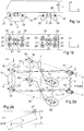
- the Figures 1a and 1b represent a vehicle having a body 1, and two bogies 2 each having two axles 21 and four wheels 22, the axles 21 and the wheels 22 being suspended from the frame 23 of the bogie 2 by a primary suspension 24 comprising four subassemblies 25 .
- the secondary suspension 3 of which each bogie 2 is provided comprises four subassemblies 31 distributed in a quadrilateral.
- the figure 2a shows four subassemblies 31 each having two rocking bases 32 and 33 disposed between one or more metal springs 4 suspension.
- the upper rocking bases 32 are secured to an interface piece 11 with the body 1, and the lower rocking bases 33 are integral with an interface piece 26 with the bogie 2, on which part are also mounted the sub-bases.
- H susp designates the height of the secondary suspension incorporating the bulk of the bed frames 32 and 33.
- the x direction is the longitudinal direction of the vehicle, which is that of its movement in a straight line.
- the direction is the transverse direction of the vehicle, and the direction z, orthogonal to the two previous ones, is the vertical direction.
- the direction u (see also figure 2b ) designates the preferred tilting axis of the rocking bases 32 and 33, and the direction v, the horizontal direction perpendicular to the directions u and z.
- u is the longitudinal direction of the bedsteads, and v is the transverse direction.
- the rocking bed bases have the function of providing a differentiated decoupling, with in particular a privileged tilting around the u-axis and a limited tilting around the v-axis of the mattresses, whereas the metal springs typically provide the obtaining the desired vertical stiffness for the secondary suspension.
- the differentiated decoupling is thus obtained thanks to tilting bed bases that have different stiffness characteristics according to the horizontal directions.
- O1 and O2 are the geometric centers of all upper bed bases 32 and 33, each bed frame 32 having a center A1, B1, C1, D1, and each bed base 33, a center A2, B2, C2, D2.
- O1 is the center of quadrilateral A1, B1, C1, D1 and O2 is the center of quadrilateral A2, B2, C2, D2.
- K x , K y and K ⁇ z respectively denote the longitudinal stiffness of the suspension (x axis), its transverse stiffness (y axis) and its yaw stiffness (body / bogie rotation around the z axis).
- the first horizontal axis u is a preferred tilting axis of the subassembly 31.
- the second horizontal axis v is a limited tilt axis (higher rigidity).
- L, ⁇ are respectively the distance and the angle of implantation of the sub-sets of secondary suspension which are defined by the customer.
- ⁇ is the orientation angle of the local coordinate system ⁇ u, v, z ⁇ with respect to the global coordinate system ⁇ x, y, z ⁇ .
- the orientation of the system is chosen based on the preferred softening direction requested by the customer.
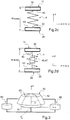
- FIGS. 2c and 2d show a secondary suspension subassembly which comprises a pair of upper and lower tilting basins 33 and one or more suspension metal springs 4 mounted between the bedsteads 32 and 33, with an upper surface 42 and lower 43 assembly of the springs 4.
- a system of high and low stops (46, 47, 48) may be located in the center of the spring or springs 4.
- the pads 60 may be of different technologies: laminated elastomeric type (parallel to the reinforcements) or non-laminated, or metal cushion type to choose.
- the pivot 50 and the pads 60 are arranged in parallel, and they act in parallel both in the vertical direction and in the horizontal directions.
- the stiffnesses are added and is therefore the sum of the radial stiffness K RP of the pivot 50 and the shear stiffness K CP of all the pads 60.
- the radial stiffness K RP of the pivot 50 is much greater than the K CP shear stiffness of the set of pads 60, it is the pivot 50 which takes up most of the horizontal force.
- the stiffnesses are also added, and the stiffness in this direction is the sum of the axial stiffness K AP of the pivot 50 and the axial stiffness K ' AP of the pads 60 taken as a whole (namely the sum stiffness of the pads), and as the axial stiffness K AP of the pivot 50 is very lower than the Axial stiffness K ' AP of the pads 60, it is the pads 60 which take up most of the vertical force.
- This parallel architecture makes it possible to significantly reduce vertical congestion, and consequently to meet the requirements of a specification in a space of reduced height.
- pairs of pads 60 in parallel with the central pivot 50 makes it possible to take up the vertical force (according to z) and to control the conical tilting ⁇ v about the axis v (limited tilting axis) while keeping a constant tilting flexibility in the other directions, including tilting about the u-axis, for which the flexibility tilt is defined primarily by the cylindrical or conical layer of laminated elastomer or not the central pivot.
- the pads 60 are represented as being cylindrical of revolution, but other shapes (polygon, etc %) can be implemented.
- the pivot 50 is shown as having a frustoconical elastic element 53, with a half opening angle ⁇ . It could also be cylindrical of revolution. The value of the opening angle ⁇ can also be between 0 ° and 60 ° and more particularly between 8 ° and 30 °.
- the pivot comprises an internal frame 51 cylindrical or frustoconical, an outer frame 52 cylindrical or frustoconical and an elastic member 53, for example laminated elastomer or not.
- the ratio between the horizontal stiffness of the central pivot 50 (radial stiffness K RP ) and the pads (stiffness in shear K CP ) can be between 5 and 50, and preferably at least equal to 10. A typical value of the order of 20 can be advocated.
- This ratio is defined essentially by the geometry (cylindrical shape of the studs, with opposite reinforcement, cylindrical or frustoconical shape of the pivot with an internal reinforcement and an external reinforcement).
- the ratio between the axial (vertical) stiffnesses of all the pads 60 (K ' AP ) and the central pivot 50 (K AP ) can be between 5 and 50. This ratio is preferably at least equal to 10. typical value of the order of 20 may be recommended.
- the vertical stiffness of the pads 60 is chosen by acting on their geometry, their characteristics (materials) as well as on the manufacturing process (elastomer laminate or not, metal cushions).
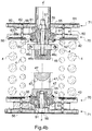
- FIGS. 4a to 4d represent a preferred embodiment of a suspension subassembly comprising two rocking bed bases according to the invention, which are mounted head to tail.
- An upper rocking bed 32 includes a central pivot 50 whose inner armature 51 is integral with a plate 71 which constitutes the interface piece 11 with the body 1 and whose outer armature 52 is integral with a plate 70 of which the lower face is the bearing face 42 of the springs 4 (here two in number).
- the opening of the cone of the elastic element 53 is directed upwards, which favors the proximity or the coincidence of the natural centers of tilting of the pivot and the studs. Disregarding the tilt stiffness induced by the compression component of the pads 60, that is to say in practice by considering the u axis, this particular arrangement of these natural centers makes it possible to obtain a lower resistance to tilting. along the axis u.
- the cylindrical pads 60 each comprise two plates 62 and 63, and a cushion 61 preferably a metal cushion, the whole being arranged between the plates 70 and 71.
- the centering of the cushions 61 is provided by pins 56. They are mounted to be diametrically opposed, with respect to the axis ZZ, and aligned in the direction u.
- On the inner frame 51 is also mounted the low elastic stop 46 and its support 46b through the stud 57 by sandwiching the assembly (50, 60, 61, 62, 63, 70, 71).
- the plates 62 and 63 are chosen from a material of sufficient hardness to withstand the contact pressure of the cushions 61.
- the lower bed base 33 which is mounted head to tail with respect to the frame 32, has a central block 50 whose inner frame 51 is integral with a plate 71, but which constitutes the interface piece 26 with the bogie 2, and whose outer armature 52 is integral with a plate 70 whose upper face is the bearing surface 43 of the springs 4.
- the described architecture for the upper bed base 32 is similar for the lower bed base 33, except that on the inner frame 51 is mounted the lower abutment support 47 via the fixing screw 58 and the opening of the cone is oriented downwards.
- the abutment 46 may come into contact with the support 47 to limit the compression amplitude of the springs 4.
- the lower abutment support 47 can be arranged to integrate the passage 47 1 with a strap (not shown) making it possible to perform the function of a lift limit limiting the amplitude. extension of the secondary suspension subassembly 31 during the lifting of the vehicle and ensuring possible preload of the spring or springs 4.
- the assembly 47 is located below the abutment 46 because, under the effect of gravity, the strap suspended after its two attachments 46c integrated with the abutment 46 is suitably in place vis-à-vis the semi contour -cylindrical 47 2 of passage 47 1 .
- the stop 46 could be permuted with the abutment support 47 and the passage 47 1 .
- the number of steps of assembly of a rocking bed base can be optimized during its industrialization by grouping in one piece of the components 51 and 71, as illustrated by the variant of the figure 5 .
- the part 51 ' has a flange 51 "which serves as a plate 71.
- the axial flexibility of the pivot 50 can be used to help the mounting of the pads 60.
- the pins 56 of centering pads 60 can be reported from the outside.
- the interface between the body 1 or the bogie 2 and the supports 70 of the metal springs is integrated at the central pivot.
- the abutment abutment 46b '/ 47' forms a collar 46 "/ 47" which has at its periphery a vertical clearance j with the outer armature 52.
- the functional clearance j is kept under normal operating conditions, in order not to clamp the tilting of the bed base.
- the flange 46 "/ 47” limits to the value of the functional clearance j the displacement in traction of the elastic element 53 of the pivot, which limits the stress in traction of the pivot during the lifting of the body and thus ensures the stop function high intrinsic to the rocking bases 32 and 33.
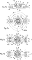
- FIGS 7a to 7d show three embodiments of the pairs of pads. In each of them, the pads are diametrically opposed with respect to the center A2 located on the axis ZZ '.
- the figure 7a (vertical section) is common to Figures 7b to 7d .
- FIG. 7c there are two pairs of pins 60 1 , 60 2 , and 60 3 , 60 4 respectively , extending on either side of the axis u over an angular sector ⁇ 1.
- Their centers P 1 , P 2 , P 3 , P 4 are situated on a straight line respectively A2P 1 , A2P 2 , A2P 3 , A2P 4 forming with the axis u an angle respectively ⁇ P 1 , ⁇ P 2 , ⁇ P 3 , ⁇ P 4 .
- An even number of pads greater than 4 could also be used.
- the value of the angles ⁇ P 1 , ⁇ P 2 , ⁇ P 3 , ⁇ P 4 is chosen to be identical in order to balance the system.
- the stiffness in compression K ' AP of the pads is greater than or equal to the axial stiffness K AP of the pivot, ie K' AP ⁇ K AP with a ratio advantageously at least equal to 5 and preferably at least equal to 10, and which can for example between 5 and 50.
- K RP ⁇ K CP with a ratio of at least 5 and preferably 10, and which may be for example between 5 and 50.
- the system is symmetrical center A2 to balance the recovery efforts.
- the section of the studs can be of any shape: they are schematized in the examples in the form of cylinders or sectors for simplify the representation. Their section can be optimized taking into account the parameters listed above ( ⁇ 1, D).
- ⁇ 1 is chosen less than 45 ° and preferably between 0 ° and 25 ° and / or ⁇ 2 can be chosen up to 60 ° and preferably between 5 ° and 25 °.
Landscapes
- Engineering & Computer Science (AREA)
- Mechanical Engineering (AREA)
- Springs (AREA)
- Vehicle Body Suspensions (AREA)
Claims (15)
- Kipprahmen, der bestimmt ist für eine Federung eines Fahrzeugs, um einerseits eine vertikale Last aufzunehmen, die von dem Wagenkasten des Fahrzeugs erzeugt wird, und um andererseits mit Kippen relative horizontale Bewegungen zu begleiten, wobei der Rahmen eine erste Halterung für dessen Montage auf einem Element des Fahrzeugs und eine zweite Halterung umfasst, die von der ersten Halterung vertikal beabstandet ist, um ein Ende einer Tragfeder aufzunehmen, dadurch gekennzeichnet, dass er parallel umfasst:- einen zentralen Drehzapfen (50) zur vertikalen Führung, umfassend ein zylindrisches oder kegelstumpfförmiges, elastisches Element (53), das zwischen einem Innenteil (51) und einem Außenteil (52) montiert ist, wobei das Innenteil (51) mit einer der ersten (70) und zweiten (71) Halterung fest verbunden ist und das Außenteil mit der anderen der ersten und zweiten Halterung fest verbunden ist, wobei der Zapfen (50) eine horizontale Steifigkeit aufweist, die größer ist als seine vertikale Steifigkeit,- und symmetrisch auf beiden Seiten des zentralen Drehzapfens angeordnet, mindestens ein Paar elastischer Klötze (60), deren Mitten auf einer ersten horizontalen Achse ausgerichtet sind und die zwischen der ersten (70) und der zweiten (71) Halterung montiert sind und eine vertikale Steifigkeit aufweisen, die in Bezug auf ihre horizontale Steifigkeit erhöht ist.
- Rahmen nach Anspruch 1, dadurch gekennzeichnet, dass das zylindrische oder kegelstumpfförmige, elastische Element (53) mindestens teilweise aus Elastomer ist.
- Rahmen nach Anspruch 2, dadurch gekennzeichnet, dass das zylindrische oder kegelstumpfförmige, elastische Element (53) ein Laminat ist.
- Rahmen nach einem der Ansprüche 1 bis 3, dadurch gekennzeichnet, dass die elastischen Klötze (60) Metallkissen sind.
- Rahmen nach einem der Ansprüche 1 bis 3, dadurch gekennzeichnet, dass die elastischen Klötze (60) mindestens teilweise aus Elastomer sind.
- Rahmen nach Anspruch 5, dadurch gekennzeichnet, dass die elastischen Klötze (60) ein Laminat sind.
- Rahmen nach einem der vorhergehenden Ansprüche, dadurch gekennzeichnet, dass das Verhältnis zwischen den vertikalen Steifigkeiten der Gesamtheit der Klötze (60) und des zentralen Drehzapfens (50) größer oder gleich 1 ist und insbesondere zwischen 5 und 50 liegt.
- Rahmen nach einem der vorhergehenden Ansprüche, dadurch gekennzeichnet, dass das Verhältnis zwischen den horizontalen Steifigkeiten des zentralen Drehzapfens (50) und der Gesamtheit der Klötze (60) größer oder gleich 1 ist und insbesondere zwischen 5 und 50 liegt.
- Rahmen nach einem der vorhergehenden Ansprüche, dadurch gekennzeichnet, dass das Verhältnis zwischen der horizontalen Steifigkeit und der vertikalen Steifigkeit des zentralen Drehzapfens (50) zwischen 2 und 5 liegt.
- Rahmen nach einem der vorhergehenden Ansprüche, dadurch gekennzeichnet, dass das Verhältnis zwischen der vertikalen Steifigkeit und der horizontalen Steifigkeit eines Klotzes (60) zwischen 50 und 500 liegt.
- Rahmen nach einem der vorhergehenden Ansprüche, dadurch gekennzeichnet, dass das zylindrische oder kegelstumpfförmige, elastische Element (53) des zentralen Drehzapfens (50) mindestens ein Paar Höhlungen (65) aufweist, die symmetrisch auf beiden Seiten des zentralen Drehzapfens (50) angeordnet sind und deren Mittelebenen auf einer zweiten horizontalen Achse ausgerichtet sind, die senkrecht zu der ersten Achse verläuft.
- Rahmen nach einem der vorhergehenden Ansprüche, dadurch gekennzeichnet, dass mindestens ein zentraler Drehzapfen (50) einen Anschlag (46, 46b', 47') aufweist, der mit dessen Innenteil (51) fest verbunden ist, und dadurch, dass dieser Anschlag (46, 46b', 47') einen Kragen (46", 47") aufweist, der durch ein Spiel j von dem Außenteil (52) des zentralen Drehzapfens (50) beabstandet ist, um die Zugbewegung des elastischen Elements (53) des zentralen Drehzapfens (50) zu begrenzen.
- Baugruppe einer Federung eines Fahrzeugs, dadurch gekennzeichnet, dass sie mindestens einen Kipprahmen nach einem der vorhergehenden Ansprüche umfasst, dessen zweite Halterung ein Ende von mindestens einer Tragfeder aufnimmt.
- Baugruppe einer Federung nach Anspruch 13, dadurch gekennzeichnet, dass sie einen ersten und einen zweiten genannten Kipprahmen umfasst, die entgegengesetzt montiert sind, wobei eine genannte Tragfeder (4) zwischen den zweiten Halterungen der zwei Rahmen angeordnet ist.
- Baugruppe nach Anspruch 14, dadurch gekennzeichnet, dass der erste Rahmen einen ersten Anschlag (46) umfasst und dadurch, dass der zweite Rahmen eine Anschlagvorrichtung (47) umfasst, die einen Gurt beinhaltet, der durch Gurthalterungen (46c) fixiert ist, die mit dem ersten Anschlag (46) fest verbunden sind, und der um eine halbzylindrische Auflage (472) verläuft, die in einer Anschlagauflage (47) ausgebildet ist, die mit dem zweiten Rahmen fest verbunden ist.
Applications Claiming Priority (1)
| Application Number | Priority Date | Filing Date | Title |
|---|---|---|---|
| FR1002409A FR2960844B1 (fr) | 2010-06-08 | 2010-06-08 | Sommier basculant et suspension secondaire le comportant |
Publications (2)
| Publication Number | Publication Date |
|---|---|
| EP2394881A1 EP2394881A1 (de) | 2011-12-14 |
| EP2394881B1 true EP2394881B1 (de) | 2018-04-11 |
Family
ID=43466860
Family Applications (1)
| Application Number | Title | Priority Date | Filing Date |
|---|---|---|---|
| EP11167944.5A Not-in-force EP2394881B1 (de) | 2010-06-08 | 2011-05-27 | Kippbettrost und damit ausgestattete Sekundärfederung |
Country Status (3)
| Country | Link |
|---|---|
| EP (1) | EP2394881B1 (de) |
| CN (1) | CN102310867B (de) |
| FR (1) | FR2960844B1 (de) |
Cited By (2)
| Publication number | Priority date | Publication date | Assignee | Title |
|---|---|---|---|---|
| RU2766940C1 (ru) * | 2021-08-13 | 2022-03-16 | Общество с ограниченной ответственностью «Всесоюзный научно-исследовательский центр транспортных технологий» (ООО «ВНИЦТТ») | Рессорное подвешивание для тележки грузового вагона |
| RU221207U1 (ru) * | 2023-06-09 | 2023-10-25 | Общество с ограниченной ответственностью "ЭКСПРЕСС ИНДУСТРИЯ" | Тележка железнодорожного грузового вагона |
Families Citing this family (1)
| Publication number | Priority date | Publication date | Assignee | Title |
|---|---|---|---|---|
| CN108248359B (zh) * | 2018-01-11 | 2023-12-05 | 东风商用车有限公司 | 一种实现刚度解耦的重型卡车发动机悬置结构 |
Family Cites Families (10)
| Publication number | Priority date | Publication date | Assignee | Title |
|---|---|---|---|---|
| NL242024A (de) * | 1958-08-05 | |||
| GB870814A (en) * | 1963-09-02 | 1961-06-21 | Metalastik Ltd | Improvements in or relating to railway vehicles |
| DE1605044C3 (de) | 1966-08-26 | 1978-09-07 | Mak Maschinenbau Gmbh | Abstützung der Brücke von Schienenfahrzeugen |
| FR1540148A (fr) | 1967-10-09 | 1968-09-20 | Maschf Augsburg Nuernberg Ag | Dispositif d'appui latéral pour la caisse d'un véhicule notamment d'un véhicule ferroviaire |
| FR2021465A1 (de) * | 1968-10-24 | 1970-07-24 | Dunlop Co Ltd | |
| FR2354229A1 (fr) * | 1976-06-11 | 1978-01-06 | Kleber Colombes | Suspension ferroviaire |
| FR2560322B1 (fr) | 1984-02-24 | 1986-06-20 | Mte | Dispositif d'appui elastique |
| CH672100A5 (de) * | 1986-12-16 | 1989-10-31 | Schweizerische Lokomotiv | |
| CN2338221Y (zh) * | 1998-07-16 | 1999-09-15 | 戚墅堰机车车辆厂 | 铁路机车的车体与转向架之间的连接装置 |
| FR2801268B1 (fr) * | 1999-11-23 | 2006-07-14 | Hutchinson | Appui pour une suspension secondaire d'un vehicule ferroviaire, notamment une locomotive |
-
2010
- 2010-06-08 FR FR1002409A patent/FR2960844B1/fr not_active Expired - Fee Related
-
2011
- 2011-05-27 EP EP11167944.5A patent/EP2394881B1/de not_active Not-in-force
- 2011-06-08 CN CN201110159781.5A patent/CN102310867B/zh not_active Expired - Fee Related
Non-Patent Citations (1)
| Title |
|---|
| None * |
Cited By (2)
| Publication number | Priority date | Publication date | Assignee | Title |
|---|---|---|---|---|
| RU2766940C1 (ru) * | 2021-08-13 | 2022-03-16 | Общество с ограниченной ответственностью «Всесоюзный научно-исследовательский центр транспортных технологий» (ООО «ВНИЦТТ») | Рессорное подвешивание для тележки грузового вагона |
| RU221207U1 (ru) * | 2023-06-09 | 2023-10-25 | Общество с ограниченной ответственностью "ЭКСПРЕСС ИНДУСТРИЯ" | Тележка железнодорожного грузового вагона |
Also Published As
| Publication number | Publication date |
|---|---|
| FR2960844B1 (fr) | 2012-07-06 |
| FR2960844A1 (fr) | 2011-12-09 |
| EP2394881A1 (de) | 2011-12-14 |
| CN102310867A (zh) | 2012-01-11 |
| CN102310867B (zh) | 2016-06-08 |
Similar Documents
| Publication | Publication Date | Title |
|---|---|---|
| CA2681344C (fr) | Dispositif de suspension primaire d'un bogie de vehicule ferroviaire | |
| EP0343482B1 (de) | Gelenkkupplung zwischen zwei Schienenfahrzeugen | |
| FR2518948A1 (fr) | Suspension primaire souple pour vehicule ferroviaire | |
| EP2007622A1 (de) | Luftfahrzeugboden, verwendung des bodens und mit dem boden ausgestatteter luftfahrzeugabschnitt | |
| EP0435755B1 (de) | Gelenkkupplung zwischen Eisenbahnwagen eines Gliederzuges | |
| FR2644743A1 (fr) | Bogie a chassis deformable | |
| FR2960843A1 (fr) | Wagon de transport a interface de compensation de hauteur par rapport au sol et ceci principalement en fonction du poids de la charge a transporter | |
| EP0082158B1 (de) | Aufhänge- und verbindungsvorrichtung zwischen drehgestellrahmen und achsbuchse | |
| EP2394881B1 (de) | Kippbettrost und damit ausgestattete Sekundärfederung | |
| EP4019366B1 (de) | Aufhängung für schienenfahrzeug mit tragachsen von orientierbaren rädern | |
| EP3222485B1 (de) | Schienenfahrzeugdrehgestell, das eine versetzte primäre federungsvorrichtung umfasst | |
| FR2497167A1 (fr) | Systeme de suspension combinee transversale et verticale pour vehicule ferroviaire | |
| FR2652865A1 (fr) | Procede de realisation de pieces elastiques a rigidites differenciees dans les trois directions par emmanchement de pieces cylindriques a armatures rigides. | |
| EP3536577B1 (de) | Schienenfahrzeug, das einen gusseisernen ladungsquerträger umfasst | |
| EP3222486B1 (de) | Schienenfahrzeugdrehgestell, das ein abgesenktes fahrgestell umfasst | |
| EP0035443A1 (de) | Aufhängung eines Eisenbahnfahrgestellrahmens an zumindest zwei Achsen und mit dieser Aufhängung versehener Fahrgestellrahmen | |
| EP2476600B1 (de) | Aufgehängtes Fahrgestell für Schienenfahrzeug | |
| CH671739A5 (de) | ||
| EP3650301B1 (de) | Kabelführungsvorrichtung für die einrichtung einer seilbahn in stadt- oder stadtrandgebieten | |
| EP4116165B1 (de) | Kette von sattelschlepperfahrzeugen und entsprechende gelenkzuggarnitur | |
| EP0035455A1 (de) | Aufhänge- und Verbindungsvorrichtung zwischen einem Drehgestellrahmen und einer Achsbuchse | |
| EP0312448B1 (de) | Elastisches Lager mit anisotropen Steifigkeitseigenschaften | |
| CH631122A5 (fr) | Suspension de vehicule. | |
| EP3829904A1 (de) | Aufhängevorrichtung, insbesondere für ein fahrzeug | |
| BE568526A (de) |
Legal Events
| Date | Code | Title | Description |
|---|---|---|---|
| AK | Designated contracting states |
Kind code of ref document: A1 Designated state(s): AL AT BE BG CH CY CZ DE DK EE ES FI FR GB GR HR HU IE IS IT LI LT LU LV MC MK MT NL NO PL PT RO RS SE SI SK SM TR |
|
| AX | Request for extension of the european patent |
Extension state: BA ME |
|
| PUAI | Public reference made under article 153(3) epc to a published international application that has entered the european phase |
Free format text: ORIGINAL CODE: 0009012 |
|
| 17P | Request for examination filed |
Effective date: 20120509 |
|
| GRAP | Despatch of communication of intention to grant a patent |
Free format text: ORIGINAL CODE: EPIDOSNIGR1 |
|
| INTG | Intention to grant announced |
Effective date: 20171107 |
|
| GRAS | Grant fee paid |
Free format text: ORIGINAL CODE: EPIDOSNIGR3 |
|
| GRAA | (expected) grant |
Free format text: ORIGINAL CODE: 0009210 |
|
| AK | Designated contracting states |
Kind code of ref document: B1 Designated state(s): AL AT BE BG CH CY CZ DE DK EE ES FI FR GB GR HR HU IE IS IT LI LT LU LV MC MK MT NL NO PL PT RO RS SE SI SK SM TR |
|
| REG | Reference to a national code |
Ref country code: GB Ref legal event code: FG4D Free format text: NOT ENGLISH |
|
| REG | Reference to a national code |
Ref country code: CH Ref legal event code: EP |
|
| REG | Reference to a national code |
Ref country code: AT Ref legal event code: REF Ref document number: 987694 Country of ref document: AT Kind code of ref document: T Effective date: 20180415 |
|
| REG | Reference to a national code |
Ref country code: IE Ref legal event code: FG4D Free format text: LANGUAGE OF EP DOCUMENT: FRENCH |
|
| REG | Reference to a national code |
Ref country code: DE Ref legal event code: R096 Ref document number: 602011047320 Country of ref document: DE |
|
| REG | Reference to a national code |
Ref country code: NL Ref legal event code: MP Effective date: 20180411 |
|
| REG | Reference to a national code |
Ref country code: LT Ref legal event code: MG4D |
|
| REG | Reference to a national code |
Ref country code: FR Ref legal event code: PLFP Year of fee payment: 8 |
|
| PG25 | Lapsed in a contracting state [announced via postgrant information from national office to epo] |
Ref country code: NL Free format text: LAPSE BECAUSE OF FAILURE TO SUBMIT A TRANSLATION OF THE DESCRIPTION OR TO PAY THE FEE WITHIN THE PRESCRIBED TIME-LIMIT Effective date: 20180411 |
|
| PG25 | Lapsed in a contracting state [announced via postgrant information from national office to epo] |
Ref country code: BG Free format text: LAPSE BECAUSE OF FAILURE TO SUBMIT A TRANSLATION OF THE DESCRIPTION OR TO PAY THE FEE WITHIN THE PRESCRIBED TIME-LIMIT Effective date: 20180711 Ref country code: NO Free format text: LAPSE BECAUSE OF FAILURE TO SUBMIT A TRANSLATION OF THE DESCRIPTION OR TO PAY THE FEE WITHIN THE PRESCRIBED TIME-LIMIT Effective date: 20180711 Ref country code: LT Free format text: LAPSE BECAUSE OF FAILURE TO SUBMIT A TRANSLATION OF THE DESCRIPTION OR TO PAY THE FEE WITHIN THE PRESCRIBED TIME-LIMIT Effective date: 20180411 Ref country code: FI Free format text: LAPSE BECAUSE OF FAILURE TO SUBMIT A TRANSLATION OF THE DESCRIPTION OR TO PAY THE FEE WITHIN THE PRESCRIBED TIME-LIMIT Effective date: 20180411 Ref country code: ES Free format text: LAPSE BECAUSE OF FAILURE TO SUBMIT A TRANSLATION OF THE DESCRIPTION OR TO PAY THE FEE WITHIN THE PRESCRIBED TIME-LIMIT Effective date: 20180411 Ref country code: AL Free format text: LAPSE BECAUSE OF FAILURE TO SUBMIT A TRANSLATION OF THE DESCRIPTION OR TO PAY THE FEE WITHIN THE PRESCRIBED TIME-LIMIT Effective date: 20180411 Ref country code: SE Free format text: LAPSE BECAUSE OF FAILURE TO SUBMIT A TRANSLATION OF THE DESCRIPTION OR TO PAY THE FEE WITHIN THE PRESCRIBED TIME-LIMIT Effective date: 20180411 Ref country code: PL Free format text: LAPSE BECAUSE OF FAILURE TO SUBMIT A TRANSLATION OF THE DESCRIPTION OR TO PAY THE FEE WITHIN THE PRESCRIBED TIME-LIMIT Effective date: 20180411 |
|
| PG25 | Lapsed in a contracting state [announced via postgrant information from national office to epo] |
Ref country code: LV Free format text: LAPSE BECAUSE OF FAILURE TO SUBMIT A TRANSLATION OF THE DESCRIPTION OR TO PAY THE FEE WITHIN THE PRESCRIBED TIME-LIMIT Effective date: 20180411 Ref country code: RS Free format text: LAPSE BECAUSE OF FAILURE TO SUBMIT A TRANSLATION OF THE DESCRIPTION OR TO PAY THE FEE WITHIN THE PRESCRIBED TIME-LIMIT Effective date: 20180411 Ref country code: HR Free format text: LAPSE BECAUSE OF FAILURE TO SUBMIT A TRANSLATION OF THE DESCRIPTION OR TO PAY THE FEE WITHIN THE PRESCRIBED TIME-LIMIT Effective date: 20180411 Ref country code: GR Free format text: LAPSE BECAUSE OF FAILURE TO SUBMIT A TRANSLATION OF THE DESCRIPTION OR TO PAY THE FEE WITHIN THE PRESCRIBED TIME-LIMIT Effective date: 20180712 |
|
| REG | Reference to a national code |
Ref country code: CH Ref legal event code: PL |
|
| REG | Reference to a national code |
Ref country code: AT Ref legal event code: MK05 Ref document number: 987694 Country of ref document: AT Kind code of ref document: T Effective date: 20180411 |
|
| PG25 | Lapsed in a contracting state [announced via postgrant information from national office to epo] |
Ref country code: PT Free format text: LAPSE BECAUSE OF FAILURE TO SUBMIT A TRANSLATION OF THE DESCRIPTION OR TO PAY THE FEE WITHIN THE PRESCRIBED TIME-LIMIT Effective date: 20180813 |
|
| REG | Reference to a national code |
Ref country code: DE Ref legal event code: R097 Ref document number: 602011047320 Country of ref document: DE |
|
| REG | Reference to a national code |
Ref country code: BE Ref legal event code: MM Effective date: 20180531 |
|
| PG25 | Lapsed in a contracting state [announced via postgrant information from national office to epo] |
Ref country code: EE Free format text: LAPSE BECAUSE OF FAILURE TO SUBMIT A TRANSLATION OF THE DESCRIPTION OR TO PAY THE FEE WITHIN THE PRESCRIBED TIME-LIMIT Effective date: 20180411 Ref country code: AT Free format text: LAPSE BECAUSE OF FAILURE TO SUBMIT A TRANSLATION OF THE DESCRIPTION OR TO PAY THE FEE WITHIN THE PRESCRIBED TIME-LIMIT Effective date: 20180411 Ref country code: CZ Free format text: LAPSE BECAUSE OF FAILURE TO SUBMIT A TRANSLATION OF THE DESCRIPTION OR TO PAY THE FEE WITHIN THE PRESCRIBED TIME-LIMIT Effective date: 20180411 Ref country code: RO Free format text: LAPSE BECAUSE OF FAILURE TO SUBMIT A TRANSLATION OF THE DESCRIPTION OR TO PAY THE FEE WITHIN THE PRESCRIBED TIME-LIMIT Effective date: 20180411 Ref country code: MC Free format text: LAPSE BECAUSE OF FAILURE TO SUBMIT A TRANSLATION OF THE DESCRIPTION OR TO PAY THE FEE WITHIN THE PRESCRIBED TIME-LIMIT Effective date: 20180411 Ref country code: SK Free format text: LAPSE BECAUSE OF FAILURE TO SUBMIT A TRANSLATION OF THE DESCRIPTION OR TO PAY THE FEE WITHIN THE PRESCRIBED TIME-LIMIT Effective date: 20180411 Ref country code: DK Free format text: LAPSE BECAUSE OF FAILURE TO SUBMIT A TRANSLATION OF THE DESCRIPTION OR TO PAY THE FEE WITHIN THE PRESCRIBED TIME-LIMIT Effective date: 20180411 |
|
| PLBE | No opposition filed within time limit |
Free format text: ORIGINAL CODE: 0009261 |
|
| STAA | Information on the status of an ep patent application or granted ep patent |
Free format text: STATUS: NO OPPOSITION FILED WITHIN TIME LIMIT |
|
| REG | Reference to a national code |
Ref country code: IE Ref legal event code: MM4A |
|
| PG25 | Lapsed in a contracting state [announced via postgrant information from national office to epo] |
Ref country code: SM Free format text: LAPSE BECAUSE OF FAILURE TO SUBMIT A TRANSLATION OF THE DESCRIPTION OR TO PAY THE FEE WITHIN THE PRESCRIBED TIME-LIMIT Effective date: 20180411 Ref country code: LI Free format text: LAPSE BECAUSE OF NON-PAYMENT OF DUE FEES Effective date: 20180531 Ref country code: CH Free format text: LAPSE BECAUSE OF NON-PAYMENT OF DUE FEES Effective date: 20180531 Ref country code: IT Free format text: LAPSE BECAUSE OF FAILURE TO SUBMIT A TRANSLATION OF THE DESCRIPTION OR TO PAY THE FEE WITHIN THE PRESCRIBED TIME-LIMIT Effective date: 20180411 |
|
| 26N | No opposition filed |
Effective date: 20190114 |
|
| GBPC | Gb: european patent ceased through non-payment of renewal fee |
Effective date: 20180711 |
|
| PG25 | Lapsed in a contracting state [announced via postgrant information from national office to epo] |
Ref country code: LU Free format text: LAPSE BECAUSE OF NON-PAYMENT OF DUE FEES Effective date: 20180527 |
|
| PG25 | Lapsed in a contracting state [announced via postgrant information from national office to epo] |
Ref country code: IE Free format text: LAPSE BECAUSE OF NON-PAYMENT OF DUE FEES Effective date: 20180527 Ref country code: GB Free format text: LAPSE BECAUSE OF NON-PAYMENT OF DUE FEES Effective date: 20180711 |
|
| PG25 | Lapsed in a contracting state [announced via postgrant information from national office to epo] |
Ref country code: BE Free format text: LAPSE BECAUSE OF NON-PAYMENT OF DUE FEES Effective date: 20180531 Ref country code: SI Free format text: LAPSE BECAUSE OF FAILURE TO SUBMIT A TRANSLATION OF THE DESCRIPTION OR TO PAY THE FEE WITHIN THE PRESCRIBED TIME-LIMIT Effective date: 20180411 |
|
| PG25 | Lapsed in a contracting state [announced via postgrant information from national office to epo] |
Ref country code: MT Free format text: LAPSE BECAUSE OF FAILURE TO SUBMIT A TRANSLATION OF THE DESCRIPTION OR TO PAY THE FEE WITHIN THE PRESCRIBED TIME-LIMIT Effective date: 20180411 |
|
| PG25 | Lapsed in a contracting state [announced via postgrant information from national office to epo] |
Ref country code: TR Free format text: LAPSE BECAUSE OF FAILURE TO SUBMIT A TRANSLATION OF THE DESCRIPTION OR TO PAY THE FEE WITHIN THE PRESCRIBED TIME-LIMIT Effective date: 20180411 |
|
| PG25 | Lapsed in a contracting state [announced via postgrant information from national office to epo] |
Ref country code: HU Free format text: LAPSE BECAUSE OF FAILURE TO SUBMIT A TRANSLATION OF THE DESCRIPTION OR TO PAY THE FEE WITHIN THE PRESCRIBED TIME-LIMIT; INVALID AB INITIO Effective date: 20110527 |
|
| PG25 | Lapsed in a contracting state [announced via postgrant information from national office to epo] |
Ref country code: MK Free format text: LAPSE BECAUSE OF NON-PAYMENT OF DUE FEES Effective date: 20180411 Ref country code: CY Free format text: LAPSE BECAUSE OF FAILURE TO SUBMIT A TRANSLATION OF THE DESCRIPTION OR TO PAY THE FEE WITHIN THE PRESCRIBED TIME-LIMIT Effective date: 20180411 |
|
| PG25 | Lapsed in a contracting state [announced via postgrant information from national office to epo] |
Ref country code: IS Free format text: LAPSE BECAUSE OF FAILURE TO SUBMIT A TRANSLATION OF THE DESCRIPTION OR TO PAY THE FEE WITHIN THE PRESCRIBED TIME-LIMIT Effective date: 20180811 |
|
| PGFP | Annual fee paid to national office [announced via postgrant information from national office to epo] |
Ref country code: FR Payment date: 20210414 Year of fee payment: 11 Ref country code: DE Payment date: 20210520 Year of fee payment: 11 |
|
| REG | Reference to a national code |
Ref country code: DE Ref legal event code: R119 Ref document number: 602011047320 Country of ref document: DE |
|
| PG25 | Lapsed in a contracting state [announced via postgrant information from national office to epo] |
Ref country code: FR Free format text: LAPSE BECAUSE OF NON-PAYMENT OF DUE FEES Effective date: 20220531 |
|
| PG25 | Lapsed in a contracting state [announced via postgrant information from national office to epo] |
Ref country code: DE Free format text: LAPSE BECAUSE OF NON-PAYMENT OF DUE FEES Effective date: 20221201 |