EP4019366B1 - Aufhängung für schienenfahrzeug mit tragachsen von orientierbaren rädern - Google Patents
Aufhängung für schienenfahrzeug mit tragachsen von orientierbaren rädern Download PDFInfo
- Publication number
- EP4019366B1 EP4019366B1 EP21215925.5A EP21215925A EP4019366B1 EP 4019366 B1 EP4019366 B1 EP 4019366B1 EP 21215925 A EP21215925 A EP 21215925A EP 4019366 B1 EP4019366 B1 EP 4019366B1
- Authority
- EP
- European Patent Office
- Prior art keywords
- chassis
- suspension
- vehicle
- axle
- assembly
- Prior art date
- Legal status (The legal status is an assumption and is not a legal conclusion. Google has not performed a legal analysis and makes no representation as to the accuracy of the status listed.)
- Active
Links
Images


Classifications
-
- B—PERFORMING OPERATIONS; TRANSPORTING
- B61—RAILWAYS
- B61F—RAIL VEHICLE SUSPENSIONS, e.g. UNDERFRAMES, BOGIES OR ARRANGEMENTS OF WHEEL AXLES; RAIL VEHICLES FOR USE ON TRACKS OF DIFFERENT WIDTH; PREVENTING DERAILING OF RAIL VEHICLES; WHEEL GUARDS, OBSTRUCTION REMOVERS OR THE LIKE FOR RAIL VEHICLES
- B61F3/00—Types of bogies
-
- B—PERFORMING OPERATIONS; TRANSPORTING
- B61—RAILWAYS
- B61C—LOCOMOTIVES; MOTOR RAILCARS
- B61C9/00—Locomotives or motor railcars characterised by the type of transmission system used; Transmission systems specially adapted for locomotives or motor railcars
- B61C9/38—Transmission systems in or for locomotives or motor railcars with electric motor propulsion
- B61C9/48—Transmission systems in or for locomotives or motor railcars with electric motor propulsion with motors supported on vehicle frames and driving axles, e.g. axle or nose suspension
-
- B—PERFORMING OPERATIONS; TRANSPORTING
- B61—RAILWAYS
- B61F—RAIL VEHICLE SUSPENSIONS, e.g. UNDERFRAMES, BOGIES OR ARRANGEMENTS OF WHEEL AXLES; RAIL VEHICLES FOR USE ON TRACKS OF DIFFERENT WIDTH; PREVENTING DERAILING OF RAIL VEHICLES; WHEEL GUARDS, OBSTRUCTION REMOVERS OR THE LIKE FOR RAIL VEHICLES
- B61F3/00—Types of bogies
- B61F3/16—Types of bogies with a separate axle for each wheel
-
- B—PERFORMING OPERATIONS; TRANSPORTING
- B61—RAILWAYS
- B61F—RAIL VEHICLE SUSPENSIONS, e.g. UNDERFRAMES, BOGIES OR ARRANGEMENTS OF WHEEL AXLES; RAIL VEHICLES FOR USE ON TRACKS OF DIFFERENT WIDTH; PREVENTING DERAILING OF RAIL VEHICLES; WHEEL GUARDS, OBSTRUCTION REMOVERS OR THE LIKE FOR RAIL VEHICLES
- B61F5/00—Constructional details of bogies; Connections between bogies and vehicle underframes; Arrangements or devices for adjusting or allowing self-adjustment of wheel axles or bogies when rounding curves
- B61F5/38—Arrangements or devices for adjusting or allowing self- adjustment of wheel axles or bogies when rounding curves, e.g. sliding axles, swinging axles
- B61F5/386—Arrangements or devices for adjusting or allowing self- adjustment of wheel axles or bogies when rounding curves, e.g. sliding axles, swinging axles fluid actuated
Definitions
- the present invention relates to the field of light railway vehicles with two axles or four half-axles.
- the invention relates more particularly to an assembly comprising an axle or two half-axles and a connecting device provided for connecting said axle or said half-axles to the chassis of a railway vehicle, which assembly is capable of running this vehicle on very degraded, winding railway tracks and/or tracks with sharp bends.
- Such a set is for example known from the document KR 101 536 658 B1 .
- the suspension of this vehicle was conventionally made with leaf springs such as those used for two-axle freight wagons.
- the new rail vehicle assembly must provide interior comfort equivalent to that experienced in modern trams, while being robust, simple, inexpensive and reliable.
- the new rail vehicle assembly ensures good vehicle guidance, regardless of the state of track deterioration, including on winding tracks and/or those with sharp bends.
- the rolling profile of the wheels is slightly conical in shape with a concave connection towards the flange. It is the shape of each wheel within a railway axle, by the difference in the right-left, inside-outside rolling radii, which allows the axle to self-center on the track when it moves laterally, without the action of external organs.
- This mechanical control allows the axle of a railway vehicle to take wide curves without wearing its flange, which is called the "bicone effect".
- the conicity i.e. the average angle at wheel-rail contact, is specific to each "wheel profile / rail profile" pair.
- a high taper is characterized by a contact capable of self-orienting the axle well, but it tends to make the axle, and therefore the vehicle, unstable.
- the bicone effect is generally sufficient to allow the axle to orient itself correctly and the lateral forces on the flanges remain low, which preserves the track and the wheels.
- the new assembly must allow lateral movements in order to filter lateral stresses generated by rolling and track defects. Similarly, this new assembly must allow for parallelism of the axles, particularly in a straight line. Poorly controlled parallelism is likely to result in a permanent drift angle of the axle and cause premature wear of the wheels or tracks, or even derailment of the vehicle.
- the new assembly must also allow individually adjustable stiffness along the vertical axis for each of the two wheels of the same axle, such a pendulum assembly advantageously making it possible to ensure a natural frequency independent of their strong load variation.
- the new assembly should also allow at least one wheel of the axle to be moved vertically and actively relative to the chassis of the rail vehicle in order to tilt the rail vehicle when cornering for greater passenger comfort.
- the new assembly's mounts could advantageously be positioned outside the wheels to improve roll stability.
- Such an ideal suspension assembly should also be adaptable to a railway vehicle equipped with two half-axles each carrying an independent wheel, instead of a two-wheel axle.
- the object of the present invention therefore aims to overcome the disadvantages of the prior art by proposing a new light railway vehicle, for example of the railcar type, which can be carried by two axles or four half-axles, and not by bogies.
- This vehicle of 25 tonnes maximum load is considered light when compared to conventional railway vehicles carried by only two bogies, and generally weighing around 50 tonnes.
- This light rail vehicle is characterized by the characteristics of claim 1.
- the control actuator via the control rod, advantageously allows forcing the yaw orientation of the wheel support axis, or even forcing the lateral inclination of the chassis relative to the track.
- the control actuator modifies the drift angle between the wheel support axis and the chassis by moving the articulation point of the suspension arm relative to the chassis or relative to the wheel support axis.
- the translational movement of the moving part of the actuator makes pivot the control rod in a substantially vertical plane so as to drive the articulation of the suspension arm forwards or backwards in the general longitudinal direction of the vehicle, which advantageously leads to a yaw movement of the wheel support axle.
- the movement of the movable part of the actuator also pivots the control rod in a substantially vertical plane so as to drive the articulation of the suspension arm upwards or downwards, which laterally tilts the chassis of the vehicle relative to the axle and makes it possible to give the chassis a heel in curves and to compensate for centrifugal effects.
- the suspension device dampens the vertical movement of the chassis relative to the wheel support axis and provides vertical comfort. It also makes it possible to locally compensate for the load state of the vehicle in order to adjust the height of the vehicle chassis relative to the wheel support axis.
- the wheel support axle is an axle equipped with two wheels
- the connecting device according to the invention causes the yaw orientation of one of the ends of the axle on one side of the vehicle in one direction, the other end of the axle which is on the other side of the vehicle is simultaneously and automatically yaw oriented in the other direction, the axle pivoting relative to the chassis around a vertical axis and serving as a mechanical twinning connection between the two wheels.
- the assembly may comprise two wheel support axles in the form of two half-axles each equipped with a wheel, and further comprise a device for twinning the pivoting of the half-axles, which, when one of the half-axles pivots relative to the chassis around a vertical axis, causes an identical pivoting but in the opposite direction of the other half-axle.
- This twinning device may be of any nature. It may for example be a twinning of the two control actuators, for example by a hydraulic servo, when an assembly according to the invention is provided on each side of the vehicle. Alternatively, it may in particular be a mechanical connection between the two half-axles.
- the articulation of the suspension arm is an elastic articulation provided to allow, with a determined stiffness, vertical movements, lateral movements and rolling movements of the chassis of the vehicle relative to the suspension arm, and to allow the yaw orientation of the wheel support axis in curves.
- the articulation of the suspension arm comprises an elastomer part, preferably of the rubber type or rubber-metal composite type, and preferably heterogeneous to obtain different stiffnesses in x, y and z.
- the amplitude of the vertical, lateral and rolling movements authorized by the articulation of the suspension arm are less than 10 millimeters, preferably less than 8 millimeters and more preferably less than 5 millimeters.
- the stiffness of the articulation of the suspension arm in x, y and z is preferably between 2 ⁇ 10 5 N/m and 2 ⁇ 10 7 N/m, more preferably between 7 ⁇ 10 5 N/m and 7 ⁇ 10 6 N/m and even more preferably between 1 ⁇ 10 6 N/m and 5 ⁇ 10 6 N/m.
- the articulation of the control rod on the chassis is an elastic articulation provided to authorize, with a determined stiffness, at least lateral movements of the control rod relative to the chassis.
- the suspension arm extends substantially horizontally along the longitudinal axis of the railway vehicle such that, when the connecting rod is pivoted by the control actuator and exerts a force on the suspension arm at the articulation, the kinematics of this connecting rod generates a vertical and inclined force component. laterally the chassis of the railway vehicle.
- the suspension arm is provided under the chassis and on the outer side of the wheel associated with it. Indeed, the fact of spreading the suspensions as far apart as possible improves the rolling resistance of the railway vehicle.
- control rod extends substantially vertically such that, when the control rod is pivoted by the control actuator and exerts a force on the suspension arm at the articulation, the kinematics of this rod generates a horizontal force component and orients the axle in yaw.
- control actuator extends substantially horizontally along the longitudinal axis of the railway vehicle so as to pivot the control rod in a vertical plane when the movable part of said control actuator is moved.
- the articulation of the suspension arm is preferably provided between the two articulations of the control rod, and more preferably in the substantially median part of the control rod, so that the point of application of the forces exerted by the control actuator on the control rod at the level of the first articulation thereof is distant from said first end of the suspension arm.
- the stroke of the actuator is amplified, which simplifies its control and the force of the efforts exerted by the control actuator on the control rod at the first articulation of the latter is increased and greater at the articulation of the suspension arm, so that the force exerted by the control actuator is amplified at the articulation of the suspension arm.
- the wheel support axle is connected to the suspension arm, between the first and second ends of said suspension arm, in any intermediate position between these two ends, and preferably at the substantially median part of said suspension arm, such that the point of application of the forces exerted by the control rod on the suspension arm at the articulation is distant from the lateral end of the wheel support axle carried by said suspension arm and that, in addition, the lateral end of the wheel support axle is also distant from the point of application of the forces exerted by the suspension device on the suspension arm.
- the position of the connection to the wheel support axle is chosen so as to distribute the loads taken up by the articulation and the suspension.
- the aim is to reduce the loads on the articulation so that these loads are exerted as much as possible on the suspension. This improves comfort and improves the fatigue resistance of the connection device.
- the intermediate position of the end of the wheel support axle on the suspension arm which is remote from the connection with the suspension, advantageously makes it possible to create a horizontal component in the transmission of forces to the wheel.
- the force resulting from the weight of the chassis is not directly transmitted by the suspension vertically towards the ground, but is broken down into a vertical component and a horizontal component which is applied along the suspension arm.
- This horizontal component creates a torque that tends to return the wheel support axle to the straight position, i.e. to a position transverse to the vehicle and its chassis.
- this vertical component automatically returns the wheel support axle to the straight position if it had previously pivoted under the action of the control rod, or maintains it in the straight position if it was already in the straight position. This action is passive and automatic. The safety of the system is greatly improved.
- the suspension of the suspension device is a pneumatic spring, preferably comprising a diaphragm or bellows capable of being inflated with compressed air.
- the new assembly according to the invention comprises a sensor between the wheel support axle and the chassis of the vehicle, this sensor being provided to measure the load state of the vehicle and regulate the pressure of the compressed air supplied to the pneumatic suspension as a function of said load state.
- the suspension device comprises a substantially vertical or inclined shock absorber of the hydraulic, oleopneumatic or hydropneumatic type.
- This shock absorber is advantageously provided with a stiffness allowing to obtain a natural frequency of the suspension of the order of Hertz, to provide vertical comfort.
- a suspension usually includes a spring element and a shock absorber, generally hydraulic, to dampen and prevent the spring from pumping.
- a hydraulic suspension for example, we can combine the spring and the shock absorber in the same organ.
- an air suspension preferred in the railway sector, we generally add a hydraulic telescopic shock absorber which calms the oscillations of the air spring by rolling oil, therefore by heat.
- the part of the control rod comprising the articulation provided in its second end is inclined relative to the vertical longitudinally towards the center of the chassis, preferably at an angle of between 10° and 65°, more preferably of between 20° and 55°, and even more preferably of between 30° and 45° relative to the vertical.
- the assembly according to the invention comprises a lateral damping device provided to connect the wheel support axle to the chassis so as to dampen the lateral stresses generated by the wheel support axle and transmitted to the chassis.
- the lateral damping device comprises two dampers arranged symmetrically with respect to the median longitudinal axis of the vehicle.
- control actuator is a hydraulic cylinder, which advantageously allows the control actuator, which has become passive in the event of a breakdown, to fulfill the role of a yaw shock absorber to guarantee satisfactory stability of the vehicle.
- vertical or horizontal we will refer to the vehicle when it is in normal conditions of use on flat and non-sloping ground.
- longitudinal we will therefore understand the general axis of the vehicle along which it moves, an axis which is the same as that of the track in the case where the latter is straight.
- horizontal plane we mean the average plane in which the vehicle is located, a plane which is parallel to that comprising the two rails of the track in the case where the latter is straight, flat and non-sloping.
- vertical axis we mean an axis which is perpendicular to the horizontal plane previously defined.
- transverse we mean a direction or an axis which extends horizontally and perpendicular to the longitudinal axis of the vehicle.
- the new assembly (0) according to the invention is preferably intended to equip a new light rail vehicle, for example with a maximum load of 25 tonnes, which is carried by only two axles (2) or four half-axles (35), and not by bogies.
- Said assembly (0) comprises at least one wheel support axle (36), which is composed in the embodiment shown in the Figures 1 to 10 of an axle (2) equipped with two wheels (3) or in the embodiment shown in the figures 11 And 12 of two half-axles (35) each equipped with a wheel (3). It also comprises at least one connecting device (1) provided for connecting said wheel support axle (362) to the chassis (9) of a railway vehicle.
- each axle (2) has a railway wheel (3) at each of its ends.
- the motorization is provided by at least one electric motor (4) which is preferably fixed to the chassis (9), but which can also be fixed to at least one axle (2).
- each axle (2) thus motorized carries at its center a reducer (5), for example of the bevel gear type with a reduction ratio defined according to the expected performances.
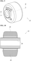
- the crown of the reducer (5) is linked in rotation to the axle (2), while the casing (6) which carries the input pinion of the reducer (5) is mounted free in rotation relative to the axle (2) which transmits the torques to the wheels (3).
- the casing (6) of the reducer (5) is for example suspended from the chassis (9) of the rail vehicle by a suspension device (34) comprising for example two upper (23) and lower (24) connecting rods which retain it in rotation.
- a suspension device (34) comprising for example two upper (23) and lower (24) connecting rods which retain it in rotation.
- Each electric motor (4) is preferably fixed under the body, and the mechanical connection (7) between the electric motor (4) and the axle (2) associated with it is preferably a homokinetic transmission, for example of the cardan type.
- each electric motor (4) is not subjected to the shocks and vibrations suffered by the axle (2) associated with it.
- the unsprung mass is lower compared to conventional railway vehicles, which is beneficial for comfort and less damaging to the track.
- this suspension is also valid for a non-driven axle (2).
- central connecting rods are provided, for example upper (23) and lower (24) connecting rods, which are connected to the axle (2) by a part equivalent to the casing (6) of the reducer (5) of the previous case, but without mechanical transmission components such as the mechanical connection (7).
- the suspension of the axle (2) via the housing (6) of the reducer (5) is only a preferred example.
- the axle (2) In order for the axle (2) to be able to yaw, it is however essential that it is provided to pivot relative to the chassis (9) of the railway vehicle around a substantially vertical axis.
- the engine (4) is preferably suspended from the chassis (9) of the railway vehicle, although this is not obligatory.
- motorized axle (2) is shown as an example in the figures, it is understood that the assembly (0) according to the invention can be provided for a non-motorized axle (2).
- an articulated connecting device for example in the form of upper (23) and lower (24) connecting rods, is provided between the housing (6) and the chassis (9) to take up, among other things, the traction and braking torques.
- the connecting device (1) according to the invention is a so-called trailing arm suspension version. As shown in the figures by way of example, such a connecting device (1) preferably equips each axle (2) of the vehicle, and is more preferably present on both sides of the vehicle, for each of the two axles (2) thereof. Although this seems of little advantage in the case of a light rail vehicle, nothing prevents the connecting device (1) from being used for a single axle (2) and/or on a single side of the vehicle.
- the connecting device (1) comprises a suspension arm (8) provided to support a lateral end of the axle (2) associated with it.
- the suspension arm (8) is preferably provided under the chassis (9) and offset laterally on the outer side of the wheel (3) associated with it. It preferably extends substantially horizontally along the longitudinal axis of the railway vehicle, i.e. parallel to the rails of the track.
- connection between the axle ends (2) and the suspension arms (8) are connections that are free to rotate around the axle axis (2) since this axle (2) rotates. These are preferably high-capacity bearings.
- the braking device is positioned between the suspension arms (8) and the wheels (3).
- the brake discs are connected to the axle (2) while the calipers are fixed to the suspension arms (8), with the brake control members located above the suspension arms (8).
- the brake discs are well ventilated, protected from ballast projections and the members are accessible for maintenance.
- the chassis (9) of the railway vehicle is connected to the axle (2) in an articulated manner by a first end (10) of the suspension arm (8), while the chassis (9) of the railway vehicle is connected and suspended from the suspension arm (8), at the second end (11) of the suspension arm (8), by means of a suspension device (12).
- the axle (2) is connected to the suspension arm (8), between the first end (10) and the second end (11) of said suspension arm (8), preferably at the level of the substantially median part of said suspension arm (8).
- the suspension device (12) comprises at least one suspension (13) mounted between the chassis (9) of the vehicle and the suspension arm (8) to absorb vertical movements, said suspension (13) being preferably provided at the second end (11) of the suspension arm (8).
- the suspension (13) of the suspension device (12) is preferably an air spring comprising a diaphragm or bellows capable of being inflated with compressed air.
- This pneumatic suspension (13) is advantageously designed in particular to manage the height of the chassis (9) of the vehicle relative to the axle (2), for example in order to take into account the load state of the vehicle and/or the heights authorized for the railway vehicle. This advantageously makes it possible to have a constant attitude for the railway vehicle, which facilitates access for people in wheelchairs for example.
- This suspension (13) can also be a hydraulic or electric spring and integrate damping. It can advantageously be controlled in extension to control and correct the vehicle's attitude.
- the suspension (13) can also be a suspension in the form of a metal spring, for example a coil spring, or an elastomer block, for example in rubber, but this type of suspension does not allow the vehicle's attitude to be corrected and provides a little less comfort.
- the pneumatic regulation is slow enough to allow dynamic filtration while driving without generating unpleasant rolling movements.
- the characteristics of this suspension are adapted to filter the vibrations generated by driving and obtain the comfort sought for public transport.
- the assembly (0) comprises a sensor provided between the chassis (9) of the vehicle and the axle (2) equipped with the connecting device (1), this sensor being provided to measure the distance between the chassis (9) and the axle (2) or the elongation of the pneumatic suspension (13) at this axle (2) and to regulate the pressure of the compressed air supplied to the pneumatic suspension (13) according to the load state of the vehicle at said axle (2).
- a sensor provided between the chassis (9) of the vehicle and the axle (2) equipped with the connecting device (1), this sensor being provided to measure the distance between the chassis (9) and the axle (2) or the elongation of the pneumatic suspension (13) at this axle (2) and to regulate the pressure of the compressed air supplied to the pneumatic suspension (13) according to the load state of the vehicle at said axle (2).
- the suspension device (12) also comprises a shock absorber (14) for example of the hydraulic, oleopneumatic or hydropneumatic type.
- This shock absorber (14) preferably extends substantially vertically or inclined, but is preferably located in a vertical plane parallel to the general longitudinal direction of the vehicle.
- the suspension (13) and the shock absorber (14) are located close and parallel to each other to operate jointly to provide a suspension device (12) adapted to the needs of the invention, in particular to provide vertical comfort and adjust the height of the chassis (9) of the vehicle relative to the axle (2).
- the shock absorber (14) has the role of damping the oscillations of the suspension (13).
- the first end (10) of the suspension arm (8) is intended to be mounted articulated to the chassis (9) of the railway vehicle by means of a control rod (15) which is preferably moved in inclination by a control actuator (16).
- This control actuator (16) comprises a body (17) mounted articulated on the chassis (9) of the vehicle, and a movable part (18) connected to a first end of the control rod (15) at a joint (19).
- the movable part (18) of the control actuator (16) is the movable part for actuating the latter, for example the movable rod in the case where the control actuator (16) is a pneumatic or hydraulic cylinder, the movable tube or the movable screw in the case where the control actuator (16) is a screw and/or nut actuator.
- the control actuator (16) is preferably a cylinder, and more preferably a hydraulic cylinder, which includes a displacement sensor to know its stroke.
- the hydraulic circuit of the cylinder is preferably designed to connect the large chamber of the cylinder on one side with the annular chamber of the opposite cylinder.
- a throttle is preferably provided on the hydraulic circuit of the cylinder, so that when the cylinder is passive, it provides hydraulic damping, in particular for the yaw orientation of the axle (2) relative to the chassis (9) of the vehicle.
- the control actuator (16) can advantageously become passive and play the role of a yaw damper. In this case, the yaw orientation of the axle (2) is achieved only by the effect of the bicone of the wheels (3).
- control actuator (16) extends substantially horizontally along the longitudinal axis of the railway vehicle, while the control rod (15) extends substantially vertically, i.e. substantially perpendicular to the control actuator (16).
- the control rod (15) is preferably in the form of an elongated part, for example a single substantially flat part (see Figures 3 and 4 ) or in the form of two parallel sides (see figures 2 , 5 and 6 ).
- the control rod (15) is in the form of a single elongated piece, the latter is taken in a yoke between the sides of the suspension chair (21) mounted in the lower part of the chassis (9).
- the articulation (22) of the suspension arm (8) can be taken in a yoke between the two parallel sides of the control rod (15).
- control rod (15) may be of substantially straight shape.
- the control rod (15) may be of a slightly curved shape in the manner of a boomerang.
- This curved shape makes it possible to connect the control rod (15) to the control actuator (16) and to the suspension arm (8) at fixing points located substantially along the same substantially vertical axis, and to connect it to the chassis (9) of the vehicle at a point offset longitudinally away from the axle.
- the two fixing points of the control rod control (15) are not aligned with the articulation (22) of the suspension arm (8), which avoids the creation of an unstable operating point, since little effort is required to move away from it.
- control actuator (16) simplifies the installation of the control actuator (16) in the embodiment shown as an example in the figures.
- control actuator (16) is positioned in a high position relative to the control rod (15); it could just as well be positioned elsewhere, for example at the bottom and on the other side of the control rod (15).
- the installation shown as an example in the figures was chosen in order to allow the installation of an anti-roll bar (25) and to place the control actuator (16) away from ballast projections.
- the location of the articulation points of the control rod (15) is justified by the desired effect of rolling the chassis (9) in coincidence with the yaw of the axle (2) and by positioning the axis of the control actuator (16) as tangent as possible to the radius described by the articulation point (19) when it rotates around the articulation point, to have similar forces and strokes in both directions during the movements of the control rod (15).
- a first end of the control rod (15) is mounted articulated at the free end of the movable part (18) of the control actuator (16), while the second end of the control rod (15) is mounted articulated on the chassis (9) at a joint (20).
- the lower part of the control rod (15) where its second end and its articulation (20) are located preferably makes an angle of approximately 30° to 45° relative to the vertical.
- axle (2) is connected to the chassis (9) via the upper (23) and lower (24) connecting rods and via the control connecting rod (15).
- These different articulation points are advantageously positioned so as to allow a parallelogram movement, which advantageously allows the pivot axis of the axle (2) to be kept substantially vertical in yaw relative to the chassis (9).
- the articulation (20) at the second end of the control rod (15) is preferably mounted on the chassis (9) of the vehicle by means of a part, called a suspension chair (21), which is fixed to said chassis (9), generally in the lower part thereof, and which provides an anchoring point usually offset downwards for the suspension arm (8) on the chassis (9) of the vehicle.
- a suspension chair (21) which is fixed to said chassis (9), generally in the lower part thereof, and which provides an anchoring point usually offset downwards for the suspension arm (8) on the chassis (9) of the vehicle.
- each axle (2) is provided to pivot in a horizontal plane on the chassis (9) of the vehicle and that the chassis (9) is preferentially suspended from said axle (2) in different zones.
- the chassis (9) is first suspended in an articulated manner on the suspension arms (8) at the level of the suspension chairs (21). As can be seen in particular on the Figures 1 to 4 , the chassis (9) is connected to the axle (2) by two upper (23) and lower (24) connecting rods rotatably connected to the axle (2), for example at the middle of said axle (2) and/or at the casing (6) of the reducer (5).
- axle (2) is pivotally connected to the chassis (9) and that it can be connected to said chassis (9) by a substantially central device such as the two upper (23) and lower (24) connecting rods or by the only connecting devices (1) of the invention when the axle (2) is equipped with a connecting device (1) at each of its two wheels (3).
- the first end (10) of the suspension arm (8) is connected in an articulated manner to the chassis (9) of the railway vehicle via the control rod (15).
- the first end (10) of the suspension arm (8) is fixed to the control rod (15) by an articulation (22), preferably provided between the articulations (19, 20) provided at the two ends of the control rod (15) and more preferably in the substantially middle part of the control rod (15).
- the articulation (22) of the suspension arm (8) is preferably an elastic articulation, which is provided to allow vertical movements, lateral movements and rolling movements of the chassis (9) of the vehicle relative to the suspension arm (8), and to allow the yaw orientation of the axle (2) in curves.
- the joint (22) of the suspension arm (8) primarily fulfills a function kinematics using the physical principle of the elasticity of matter and preferably includes an elastomer part. It is preferably an elastic articulation (22) of the anti-vibration type comprising an external ring (28) and an internal ring (29) with an elastic material (30) between the two. Its purpose is to filter the transmission of vibrations generated by rolling.
- the elastic material (30) is preferably made of rubber, plastic or other materials meeting stiffness and mechanical resistance criteria compatible with the mechanical forces received by the articulation (22) of the suspension arm (8).
- This elastomer part may be heterogeneous, for example of the rubber type, or composite, for example of the rubber-metal type.
- the elastic material (30) of the articulation (22) of the suspension arm (8) may have recesses to obtain different stiffnesses in x, y and z. This type of elastic articulation is known to those skilled in the art and an example is shown in the Figures 9 and 10 .
- the stiffness of the articulation (22) of the suspension arm (8) is adapted so as to limit the amplitude of the movements.
- the articulation (22) of the suspension arm (8) is provided to allow vertical, lateral and rolling movements whose amplitude is less than 10 millimeters, preferably less than 8 millimeters and more preferably less than 5 millimeters.
- the control actuator (16) pivots the control rod (15)
- the first end (10) of the suspension arm (8) is moved longitudinally, which mainly has the effect of pivoting the axle (2) in a yaw direction, and also has the effect of laterally tilting the chassis (9) of the vehicle relative to the axle (2) and therefore to the track.
- the assembly (0) of the invention advantageously makes it possible both to orient the axle (2) in yaw in curves and to give heel to the chassis (9) in curves while providing a damping effect on any vertical, lateral and rolling movements of the chassis (9) relative to the axle (2).
- the articulation (20) provided at the second end of the control rod (15) can also be an elastic articulation substantially similar to the articulation (22) of the suspension arm (8). This thus improves the filtration of vibrations and also allows the control rod (15) to oscillate slightly laterally to provide lateral suspension, a very important suspension in the railway field, in particular during contact of the wheel flanges on the track.
- This lateral suspension is preferably supplemented by a lateral damping device (31), comprising for example two shock absorbers (32, 33), preferably of hydraulic and telescopic types.
- These two shock absorbers (32, 33) are preferably provided symmetrically with respect to the median longitudinal axis of the vehicle, along the same transverse axis, above and substantially in the center of the axle (2), between the housing (6) of the reducer (6) of the axle (2) and the chassis (9).
- the two lateral shock absorbers (32, 33) are preferably connected to the chassis (9) and to the axle (2) in the central part of the latter to absorb the numerous lateral stresses undergone by the axle (2).
- the control actuator (16) of the connecting device (1) can be operated by the driver of the railway vehicle.
- the control actuator (16) of the connecting device (1) can also be controlled by an automatic servo device.
- an automatic servo device By means of a device for determining the curvature of the track, for example a GPS, feelers, cameras, or the like, this servo device learns the layout of the railway track and measures the curve that is in front of the vehicle in order to control the control actuator (16) to steer the axle (2) and tilt the vehicle towards the center of the curve.
- control actuator (16) is fixed to the chassis (9) of the railway vehicle and is connected to the control rod (15) so as to produce a lever arm.
- stroke of the movable part (18) of the control actuator (16) is greater than that of the articulation (22) of the suspension arm (8).
- This configuration facilitates the control of the control actuator (16) because the useful stroke at the articulation (22) is small, of the order of a centimeter, for example between 20 and 40 millimeters.
- suspension regulation and the design of the suspension arms (8), its articulations, the suspensions (13) and the shock absorbers (14) give the vehicle good roll stability.
- the anti-roll bar (25) is preferably mounted articulated on the sides at the level of the suspension chairs (21). It extends on each side towards the axle (2) by a lever (26) for example substantially horizontal, and is connected on each side to a suspension arm (8) by a connecting rod (27) for example substantially vertical.
- Roll stability can be ensured by controlling the suspension device (12), for example by independent right-left trim control.
- This control can also make it possible to travel on tracks with significant differences in transverse level between two points on the railway track, this type of defect also being referred to as lefts.
- the chassis (9) of the vehicle is torsionally rigid. Indeed, it should be noted that for crossing lefts, the chassis (9) must be sufficiently flexible in torsion. If the chassis (9) is too rigid, an anti-roll bar (25) can also be provided on only one of the two axles (2).
- the geometry of the means of each connecting device (1) according to the invention is preferably provided so that in static the lower part of the control rod (15) where its articulation (20) is located preferably makes an angle of approximately 30° to 45° relative to the vertical and so that the articulation point (22) of the control rod (15) to the suspension arm (8) is almost fixed in vertical.
- the articulation point (20) of the control rod (15) to the chassis (9) is located downwards and offset, preferably towards the chassis (9), and the articulation point (22) of the control rod (15) to the suspension arm (8) is located above the articulation point (20) and offset towards the axle (2).
- moving this articulation point relative to the chassis (9) changes the inclination of the control rod (15).
- the articulation point (20) of the control rod (15) to the chassis (9) rises or falls, which causes the chassis (9) to roll.
- This geometry is also designed for stops or low-speed traffic on curves that may be raised. In these cases, the vehicle leans to the inside of the track and the axle (2) automatically yaws towards the centre of the curve. This avoids the risk of derailment.
- the axle (2) rotates around its center about a quasi-vertical axis, and the two inclined control rods (15) generate opposing longitudinal forces which generate a straight-line restoring torque, which is very advantageous in the event of failure of the connecting device (1) according to the invention.
- control actuators (16) located on the inside of the curve are actuated so that their movable part (18) is moved in extension.
- the control actuators (16) located on the inside of the curve are actuated so that their movable part (18) is moved in extension.
- the output of a movable part (18) pivots the control rod (15) associated with it at the articulation (20) provided at its second end.
- the control rod (15) being connected to a suspension arm (8) at the articulation (22), the pivoting of the control rod (15) exerts forces on the suspension arm (8) associated with it, these forces tending both to move the suspension arm (8) longitudinally towards the center of the chassis (9) (in the preferred case and illustrated as an example where the control rod (15) is placed on the side of the center of the chassis (9), since it is possible to do the opposite), and the articulation point (20) located on the inside of the curve is moved down.
- each of the axles (2) pivot, causing them to yaw and allow them to follow the curve, each axle (2) then being pivoted in the manner of a steering axle.
- the vertical forces exerted on the suspension arms (8) located on the inner side of the curve do not allow the suspension arms (8) to be lifted but are transmitted to the chassis (9).
- the suspension arms (8) are integral with the axles (2) which carry the wheels (3), and these - due to the weight of the vehicle - cannot be lifted off the rails.
- the axles (2) cannot therefore move vertically relative to the rails.
- the vertical forces exerted on the suspension arms (8) result in the chassis (9) moving closer to or further away from the suspension arm (8).
- control actuator (16) In the preferred case where there is a control actuator (16) on both sides of the axle (2), the two control actuators (16) are preferably servo-controlled in opposition. In the event of a servo failure or in the event of a large curve or even a straight line, these control actuators (16) become passive and become simple yaw dampers, an important function for the stability of the vehicle.
- the axles (2) of a railway vehicle can be oriented in yaw and, preferably, the chassis (9) of said vehicle can also be inclined laterally in roll, so that the railway vehicle negotiates the curve better, with increased comfort, and by limiting the wear of the wheels (3) and the rails.
- the operating principle is substantially the same. Indeed, if the connecting device (1) is located on the inside of the curve, its operation is identical to that described above. If the connecting device (1) is located on the outside of the curve, the movable part (18) of the control actuator (16) is retracted, which causes the control rod (15) to pivot so that the latter exerts forces on the suspension arm (8) associated with it. These forces tend both to move the suspension arm (8) longitudinally away from the center of the chassis (9) and to move the articulation point (20) located on the outside of the curve vertically upwards. As before, these forces then result respectively in a yaw orientation of the axle to follow the curve and a lateral inclination of the chassis (9) towards the inner side of the curve, and vice versa if the connecting device (1) is on the outer side of the curve.
- the assembly (0) comprises two control actuators (16), namely a control actuator (16) provided at each of the wheels (3) of said axle (2).
- the pivoting of the axle (2) is carried out by the two control actuators (16), which are preferably hydraulic, but it is also materialized by central connecting rods (23, 24) which retain the axle (2) in rotation or by a similar device.
- the assembly (0) comprises a control actuator (16) at each of the two wheels (3).
- These two control actuators (16) operate in opposition, that is to say that when the movable part (18) of one of the control actuators (16) retracts, the movable part (18) of the other control actuator (16) moves in extension, and vice versa.
- the pivoting of the axle (2) is carried out by the two control actuators (16) without any articulation point (materialized for example by connecting rods (23, 24)) connecting the middle part of the axle (2) to the chassis (9) being necessary, the latter can therefore be optional.
- the assembly (0) comprises a control actuator (16) at each of the two wheels (3).
- These two control actuators (16) do not operate in opposition, but individually and autonomously, which advantageously provides redundancy and/or dampens the yaw movements of the axle.
- an articulation point connects the middle part of the axle (2) to the chassis (9), for example by means of an articulation device such as the connecting rods (23, 24) or another similar device.
- the assembly (0) comprises a single control actuator (16) which is at the level of one of the two wheels (3).
- an articulation point connects the middle part of the axle (2) to the chassis (9), for example by means of an articulation device such as the connecting rods (23, 24) or another similar device.
- Such an embodiment allows the vehicle to adapt to height differences between the two rails of a track, and thus to be able to advantageously limit body twists when driving on a left track (not flat) due to a vertical movement of the independent wheels which can be different on the two sides of the vehicle.
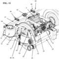
- the assembly (0) therefore comprises two wheel support axles (36), which are the half-axles (35) each carrying a wheel (3) at their end, the chassis (9) and two connecting devices (1) provided for connecting each wheel support axle (36) to the chassis (9).
- the end of the half-axle (35) is carried by the suspension arm (8) in an intermediate position between the two ends (10) and (11) of the latter, and the suspension arm is connected at its first end (10) to the control rod (15) actuated by the actuator (16) and at its second end (11) to the suspension device (12) with suspension (13).
- the longitudinal suspension arms (8) are rigidly connected to two transverse suspension arms (37) which are themselves connected at their other end, by means of a ball-and-socket joint (38), to a flexible support (39) fixed to the chassis (9).
- the wheel (3) is connected to the mechanics of the reducer (5) by the mechanical transmission link (7).
- the disc brake systems are fixed to the housing (6), the disc linked to the transmission conventionally rotates at the speed of the wheel.
- Electronic anti-lock devices ABS or road EBS can be transferred. It is possible to compare the rotation speeds of one wheel relative to the other in the event of a wheel slipping, for example.
- the casing (6), the engine (4) and the braking systems are fixed to the chassis (9) of the vehicle, and are therefore suspended and not subject to vibrations and shocks due to the rolling of the wheels (3) on the rails.
- the assembly advantageously comprises a twinning device (40) which makes it possible to transmit the yaw orientation movement of one of the half-axles (35) to the other half-axle. Thanks to this twinning device (40), when one of the half-axles pivots relative to the chassis (9) around a vertical axis located in the vicinity of the ball joint (38), the second half-axle also pivots in an identical manner but in the opposite direction.
- this twinning device (40) is a mechanical connection between the two half-axles (35), which comprises a connecting crossmember (41), which extends from one side of the vehicle to the other and which is fixed to the chassis (9) by means of a pivoting articulation (42) along the axis vertical, and a twin connecting rod (43) on each side, which is fixed on the one hand by a ball-and-socket joint (44) to one end of the connecting crosspiece (41) and on the other hand by a ball-and-socket joint (45) to the connecting rod (15).
- a connecting crossmember (41) which extends from one side of the vehicle to the other and which is fixed to the chassis (9) by means of a pivoting articulation (42) along the axis vertical, and a twin connecting rod (43) on each side, which is fixed on the one hand by a ball-and-socket joint (44) to one end of the connecting crosspiece (41) and on the other hand by a ball-and-socket joint (
- twin rods (43) can alternatively be directly attached by a ball-and-socket joint to the suspension arm (8).
- friction pads (46), for example of the smoothing type, can be provided on the connecting crosspiece (41) to dampen by dry friction the pivoting movements of the connecting crosspiece (41) around the vertical axis.
- the control rod (15) is thus connected to the chassis (9) by its articulation (20), via the actuator (16) to which it is connected by its articulation (19) and possibly via the connecting crosspiece (41) and the twin rod (43) to which it can be connected by its articulation (45).
- the yaw movement of the half-axles (35) is thus obtained on one side for the first half-axle, by the longitudinal movement of the articulation (22) due to the variation in inclination of the connecting rod (15) controlled by the actuator (16).
- the movement of the connecting rod (15) simultaneously causes the connecting cross member (41) to rotate under the action of the twin connecting rod (43), which in turn causes the second twin connecting rod (43) to move and the connecting rod (15) on the other side to tilt in the opposite direction.
- the lateral suspension is provided by the flexibility of the support (39) and/or the flexibility of the connecting rods (15) and the links of the half-axle joints (35). If necessary, this flexibility can be damped by the transverse shock absorbers (33).
- actuator 16 may be in damping mode or removed for large radius tracks. It may be present on one side only or on each side for redundancy reasons.
- the inclination of the connecting rods (15) advantageously allows for a return to alignment by gravity.
- a torsion bar (25) can also be provided as in the previous version to limit rolling for example.
- the unsprung masses are advantageously limited to the wheels (3) and part of the longitudinal suspension arms (8). Comfort is optimized and track wear is reduced.
- the damping of the yaw movement can be very simply produced at the level of the connecting crosspiece (41) by friction of the slider type pads (46).
- the assembly according to the invention was designed for a light railway vehicle with two axles or four half-axles, it is obvious to those skilled in the art to adapt this assembly to other vehicles.
Landscapes
- Engineering & Computer Science (AREA)
- Mechanical Engineering (AREA)
- Chemical & Material Sciences (AREA)
- Combustion & Propulsion (AREA)
- Transportation (AREA)
- Vehicle Body Suspensions (AREA)
Claims (16)
- Baugruppe (0), die ein Fahrgestell (9) eines Schienenfahrzeugs, mindestens eine Radträgerachse (36), die eine mit zwei Rädern (3) ausgestattete Achse (2) oder eine mit einem Rad (3) ausgestattete Halbachse (35) ist, und mindestens eine Verbindungsvorrichtung (1) umfasst, die zum Verbinden der Radträgerachse (36) mit dem Fahrgestell (9) vorgesehen ist, wobei die Radträgerachse (36) in Bezug auf das Fahrgestell (9) um eine im Wesentlichen vertikale Achse drehbar ist und die Verbindungsvorrichtung (1) folgende Mittel umfasst:• ein Stellelement (16) mit einem Körper (17) und einem beweglichen Teil (18), wobei der Körper (17) des Stellelements (16) zur Verbindung mit dem Fahrgestell (9) vorgesehen ist;• eine Antriebsstange (15), deren erstes Ende über ein Gelenk (19) am freien Ende des beweglichen Teils (18) des Stellelements (16) angebracht ist, während ihr zweites Ende über ein weiteres Gelenk (20) am Fahrgestell (9) des Fahrzeugs angebracht ist:• einen Aufhängungsarm (8), der ein seitliche Ende der Radträgerachse (36) in einer mittleren Position, vorzugsweise im Wesentlichen in der Mitte, zwischen einem ersten Ende (10) und einem zweiten Ende (11) des Aufhängungsarms (8) trägt,• eine Aufhängungsvorrichtung (12) mit mindestens einer Aufhängung (13), die zwischen dem Fahrgestell (9) und dem zweiten Ende (11) des Aufhängungsarms (8) vorgesehen ist, um vertikale Bewegungen abzufedern und zu dämpfen; wobei diese Mittel so angeordnet sind, dass sich die Radträgerachse (36) in Bezug auf das Fahrgestell (9) um eine vertikale Achse dreht, wenn die Antriebsstange (15) durch das Stellelement (16) gedreht wird,dadurch gekennzeichnet, dass das erste Ende (10) des Aufhängungsarms (8) über ein Gelenk (22) gelenkig an der Antriebsstange (15) montiert ist.
- Baugruppe (0) nach Anspruch 1, die zwei Radträgerachsen (36) in Form von zwei Halbachsen (35) umfasst, die jeweils mit einem Rad (3) ausgestattet sind, dadurch gekennzeichnet, dass sie außerdem eine Kopplungsvorrichtung (40) zum Drehen der Halbachsen (35) umfasst, die, wenn sich eine der Halbachsen (35) in Bezug auf das Fahrgestell (9) um eine vertikale Achse dreht, eine identische Drehbewegung, jedoch in entgegengesetzter Richtung der anderen Halbachse (35) bewirkt.
- Baugruppe (0) nach Anspruch 2, dadurch gekennzeichnet, dass die Kopplungsvorrichtung (40) für das Drehen der Halbachsen (35) eine mechanische Verbindung ist, die Folgendes umfasst:eine Querverbindung (41), die über ein Drehgelenk (42) in vertikaler Achse am Fahrgestell (9) befestigt ist und sich von einer Seite des Fahrgestells (9) zur anderen erstreckt, undauf jeder Seite des Fahrgestells (9) eine Verbindungsstange (43), die einerseits über ein Kugelgelenk (44) an einem Ende der Querverbindung (41) und andererseits über ein Kugelgelenk (45) an der Stange (15) oder dem Aufhängungsarm (8) befestigt ist.
- Baugrupe (0) nach einem der vorhergehenden Ansprüche, dadurch gekennzeichnet, dass der Teil der Antriebsstange (15), der mit dem Gelenk (20) in ihrem zweiten Ende ausgestattet ist, in Annäherung an die Mitte des Fahrgestells (9) in Bezug auf die Vertikale in Längsrichtung geneigt ist, vorzugsweise in einem Winkel zwischen 10° und 65°, bevorzugter zwischen 20° und 55° und noch bevorzugter zwischen 30° und 45° in Bezug auf die Vertikale.
- Baugruppe (0) nach einem der vorhergehenden Ansprüche, dadurch gekennzeichnet, dass das Stellelement (16) ein Hydraulikzylinder ist.
- Baugruppe (0) nach einem der vorhergehenden Ansprüche, dadurch gekennzeichnet, dass das Gelenk (22) des Aufhängungsarms (8) ein elastisches Gelenk ist, das dazu vorgesehen ist, mit einer bestimmten Steifheit vertikale Ausschläge, seitliche Ausschläge und Wankbewegungen des Fahrgestells (9) in Bezug auf den Aufhängungsarm (8) zuzulassen, und um die Gierausrichtung der Radträgerachse (36) in Kurven zuzulassen, wobei die Steifheit des Gelenks (22) in x-, y- und z-Richtung vorzugsweise zwischen 2 × 10⁵ N/m und 2 × 10⁷ N/m, bevorzugter zwischen 7 × 10⁵ N/m und 7 × 10⁶ N/m und noch bevorzugter zwischen 1 × 10⁶ N/m und 5 × 10⁶ N/m liegt.
- Baugruppe (0) nach einem der vorhergehenden Ansprüche, dadurch gekennzeichnet, dass sich der Aufhängungsarm (8) im Wesentlichen horizontal entlang der Längsachse des Schienenfahrzeugs erstreckt, so dass die Kinematik der Verbindungsstange eine vertikale Kraftkomponente erzeugt und das Fahrgestell (9) des Schienenfahrzeugs seitlich neigt, wenn die Stange (15) durch das Stellelement (16) gedreht wird und eine Kraft auf den Aufhängungsarm (8) am Gelenk (22) ausübt.
- Baugruppe (0) nach einem der vorhergehenden Ansprüche, dadurch gekennzeichnet, dass der Aufhängungsarm (8) unter dem Fahrgestell (9) und an der Außenseite des damit verbundenen Rades (3) vorgesehen ist, um das Rollverhalten des Schienenfahrzeugs zu verbessern.
- Baugruppe (0) nach einem der vorhergehenden Ansprüche, dadurch gekennzeichnet, dass sich das Stellelement (16) im Wesentlichen horizontal entlang der Längsachse des Schienenfahrzeugs erstreckt und dass sich die Antriebsstange (15) im Wesentlichen vertikal erstreckt, so dass die Antriebsstange (15) durch das Stellelement (16) in einer vertikalen Ebene gedreht wird und die Radträgerachse (36) in Gierachse ausrichtet, wenn der bewegliche Teil (18) des Stellelements (16) verschoben wird.
- Baugruppe (0) nach einem der vorhergehenden Ansprüche, dadurch gekennzeichnet, dass das Gelenk (22) des Aufhängungsarms (8) vorzugsweise zwischen den beiden Gelenken (19, 20) der Antriebsstange (15) und noch bevorzugter in dem im Wesentlichen mittleren Teil der Antriebsstange (15) vorgesehen ist, so dass der Schwerpunkt der Kräfte, die von dem Stellelement (16) auf die Antriebsstange (15) an deren erstem Gelenk (19) ausgeübt werden, von dem ersten Ende (10) des Aufhängungsarms (8) entfernt ist.
- Baugruppe (0) nach einem der vorhergehenden Ansprüche, dadurch gekennzeichnet, dass die Aufhängung (13) der Aufhängungsvorrichtung (12) eine Luftfeder ist, die vorzugsweise eine Membran oder einen Balg umfasst, die/der sich mit Druckluft aufblähen kann.
- Baugruppe (0) nach einem der vorhergehenden Ansprüche, dadurch gekennzeichnet, dass sie einen Sensor zwischen der Radträgerachse (36) und dem Fahrgestell (9) umfasst, wobei dieser Sensor dazu vorgesehen ist, den Beladungszustand des Fahrzeugs zu messen und den Druck der Luft, die der Radaufhängung (13) zugeführt wird, in Abhängigkeit von diesem Beladungszustand zu regulieren.
- Baugruppe (0) nach einem der vorhergehenden Ansprüche, dadurch gekennzeichnet, dass die Aufhängungsvorrichtung (12) eine im Wesentlichen vertikale oder geneigte Federung (14) hydraulischer, oleopneumatischer oder hydropneumatischer Art umfasst.
- Baugruppe (0) nach einem der vorhergehenden Ansprüche, dadurch gekennzeichnet, dass das Gelenk (20) der Antriebsstange (15) am Fahrgestell (9) ein elastisches Gelenk ist, das dazu vorgesehen ist, mit einer bestimmten Steifheit zumindest seitliche Auslenkungen der Antriebsstange (15) in Bezug auf das Fahrgestell (9) zuzulassen.
- Baugruppe (0) nach einem der vorhergehenden Ansprüche, dadurch gekennzeichnet, dass sie eine seitliche Dämpfungsvorrichtung (31) umfasst, die vorgesehen ist, um die Radträgerachse (36) mit dem Fahrgestell (9) zu verbinden, so dass die seitlichen Beanspruchungen, die von der Radträgerachse (36) erzeugt und auf das Fahrgestell (9) übertragen werden, abgefedert werden.
- Baugruppe (0) nach einem der vorhergehenden Ansprüche, dadurch gekennzeichnet, dass die seitliche Dämpfungsvorrichtung (31) zwei Federungen (32, 33) umfasst, die symmetrisch zur mittleren Längsachse des Fahrzeugs angeordnet sind.
Applications Claiming Priority (1)
| Application Number | Priority Date | Filing Date | Title |
|---|---|---|---|
| FR2014177A FR3118446B1 (fr) | 2020-12-28 | 2020-12-28 | Suspension pour vehicule ferroviaire a deux essieux |
Publications (3)
| Publication Number | Publication Date |
|---|---|
| EP4019366A1 EP4019366A1 (de) | 2022-06-29 |
| EP4019366B1 true EP4019366B1 (de) | 2024-11-06 |
| EP4019366C0 EP4019366C0 (de) | 2024-11-06 |
Family
ID=75339869
Family Applications (1)
| Application Number | Title | Priority Date | Filing Date |
|---|---|---|---|
| EP21215925.5A Active EP4019366B1 (de) | 2020-12-28 | 2021-12-20 | Aufhängung für schienenfahrzeug mit tragachsen von orientierbaren rädern |
Country Status (2)
| Country | Link |
|---|---|
| EP (1) | EP4019366B1 (de) |
| FR (1) | FR3118446B1 (de) |
Families Citing this family (3)
| Publication number | Priority date | Publication date | Assignee | Title |
|---|---|---|---|---|
| CN115991214B (zh) * | 2022-12-23 | 2025-08-08 | 中车株洲电力机车有限公司 | 一种轨道车辆底架设备的可调节悬挂臂结构 |
| FR3154372A1 (fr) * | 2023-10-18 | 2025-04-25 | Société Nationale SNCF | Bogie de véhicule ferroviaire comprenant des roues orientables |
| CN118275139B (zh) * | 2024-06-03 | 2024-08-06 | 驰田汽车技术研发武汉有限公司 | 一种双转向前桥检测装置及四轴重卡底盘结构 |
Family Cites Families (6)
| Publication number | Priority date | Publication date | Assignee | Title |
|---|---|---|---|---|
| JPS5790260A (en) * | 1980-11-25 | 1982-06-04 | Fuji Heavy Ind Ltd | Single shaft truck |
| JPS5799459A (en) * | 1980-12-11 | 1982-06-21 | Fuji Heavy Ind Ltd | Uniaxial truck device |
| JP2001001896A (ja) * | 1999-06-22 | 2001-01-09 | Mitsubishi Heavy Ind Ltd | 鉄道車両用の一軸独立車輪台車 |
| KR101536658B1 (ko) * | 2014-03-21 | 2015-07-16 | 한국철도기술연구원 | 철도차량용 능동 조향 제어를 위한 조향 액추에이터 장치 |
| DE102014214055A1 (de) * | 2014-07-18 | 2016-01-21 | Siemens Aktiengesellschaft | Fahrwerk für ein Schienenfahrzeug |
| WO2018153436A1 (de) * | 2017-02-21 | 2018-08-30 | Siemens Ag Österreich | Fahrwerk für schienenfahrzeuge |
-
2020
- 2020-12-28 FR FR2014177A patent/FR3118446B1/fr active Active
-
2021
- 2021-12-20 EP EP21215925.5A patent/EP4019366B1/de active Active
Also Published As
| Publication number | Publication date |
|---|---|
| EP4019366A1 (de) | 2022-06-29 |
| EP4019366C0 (de) | 2024-11-06 |
| FR3118446B1 (fr) | 2025-03-14 |
| FR3118446A1 (fr) | 2022-07-01 |
Similar Documents
| Publication | Publication Date | Title |
|---|---|---|
| EP4019366B1 (de) | Aufhängung für schienenfahrzeug mit tragachsen von orientierbaren rädern | |
| EP1616731B1 (de) | Fahrzeug mit Verbindung zum Boden zur unabhängigen Radaufhängung und zur aktiven Regelung des Fahrzeugaufbauniveaus | |
| CA2682931C (fr) | Bogie pour vehicule ferroviaire | |
| FR2950569A3 (fr) | Agencement de ressorts pour reguler le niveau dans un vehicule | |
| EP0420922B1 (de) | Eisenbahndrehgestell mit verbessertem stabilitäts- und kurvenverhalten | |
| EP1363795A1 (de) | Aufhängungsvorrichtung für ein kraftfahrzeugrad | |
| WO2004058521A1 (fr) | Dispositif de support de roue a triple charnière, dispositif de suspension et véhicule comprenant ledit dispositif de support | |
| EP2134583A1 (de) | Primäraufhängung für ein drehgestell eines schienenfahreugs | |
| BE1000941A4 (fr) | Guidage d'essieux montes pour bogies, a grande vitesse de deplacement, de vehicules ferroviaires et procede pour equiper des bogies de ce guidage d'essieux montes. | |
| WO2006067087A1 (fr) | Essieu suspendu pour véhicule | |
| WO2008125500A2 (fr) | Bogie pour vehicule ferroviaire | |
| BE824761Q (fr) | Perfectionnements aux suspensions de vehicules ferroviaires | |
| JPH07172314A (ja) | 鉄道車両及び鉄道車両用台車 | |
| EP3222486B1 (de) | Schienenfahrzeugdrehgestell, das ein abgesenktes fahrgestell umfasst | |
| FR2563487A1 (fr) | Bogie et vehicule ferroviaire ainsi que procede pour realiser une suspension de secours | |
| EP2476600B1 (de) | Aufgehängtes Fahrgestell für Schienenfahrzeug | |
| EP2822833B1 (de) | Traverse zur absorption in die länge wirkender kräfte für eine pendelvorrichtung | |
| EP0981472B1 (de) | Linear steuerbarer boggie | |
| EP4116165B1 (de) | Kette von sattelschlepperfahrzeugen und entsprechende gelenkzuggarnitur | |
| CH631122A5 (fr) | Suspension de vehicule. | |
| FR2572348A1 (fr) | Ensemble d'essieu orientable guide pour vehicules sur rails | |
| EP3838706B1 (de) | Fahrgestell eines schienenfahrzeugs | |
| BE426246A (de) | ||
| BE880297Q (fr) | Bogies articules pour wagons de chemins de fer | |
| BE392447A (de) |
Legal Events
| Date | Code | Title | Description |
|---|---|---|---|
| PUAI | Public reference made under article 153(3) epc to a published international application that has entered the european phase |
Free format text: ORIGINAL CODE: 0009012 |
|
| STAA | Information on the status of an ep patent application or granted ep patent |
Free format text: STATUS: THE APPLICATION HAS BEEN PUBLISHED |
|
| AK | Designated contracting states |
Kind code of ref document: A1 Designated state(s): AL AT BE BG CH CY CZ DE DK EE ES FI FR GB GR HR HU IE IS IT LI LT LU LV MC MK MT NL NO PL PT RO RS SE SI SK SM TR |
|
| STAA | Information on the status of an ep patent application or granted ep patent |
Free format text: STATUS: REQUEST FOR EXAMINATION WAS MADE |
|
| 17P | Request for examination filed |
Effective date: 20221221 |
|
| RBV | Designated contracting states (corrected) |
Designated state(s): AL AT BE BG CH CY CZ DE DK EE ES FI FR GB GR HR HU IE IS IT LI LT LU LV MC MK MT NL NO PL PT RO RS SE SI SK SM TR |
|
| GRAP | Despatch of communication of intention to grant a patent |
Free format text: ORIGINAL CODE: EPIDOSNIGR1 |
|
| STAA | Information on the status of an ep patent application or granted ep patent |
Free format text: STATUS: GRANT OF PATENT IS INTENDED |
|
| INTG | Intention to grant announced |
Effective date: 20240806 |
|
| GRAS | Grant fee paid |
Free format text: ORIGINAL CODE: EPIDOSNIGR3 |
|
| GRAA | (expected) grant |
Free format text: ORIGINAL CODE: 0009210 |
|
| STAA | Information on the status of an ep patent application or granted ep patent |
Free format text: STATUS: THE PATENT HAS BEEN GRANTED |
|
| AK | Designated contracting states |
Kind code of ref document: B1 Designated state(s): AL AT BE BG CH CY CZ DE DK EE ES FI FR GB GR HR HU IE IS IT LI LT LU LV MC MK MT NL NO PL PT RO RS SE SI SK SM TR |
|
| REG | Reference to a national code |
Ref country code: GB Ref legal event code: FG4D Free format text: NOT ENGLISH |
|
| REG | Reference to a national code |
Ref country code: CH Ref legal event code: EP |
|
| REG | Reference to a national code |
Ref country code: DE Ref legal event code: R096 Ref document number: 602021021347 Country of ref document: DE |
|
| REG | Reference to a national code |
Ref country code: IE Ref legal event code: FG4D Free format text: LANGUAGE OF EP DOCUMENT: FRENCH |
|
| U01 | Request for unitary effect filed |
Effective date: 20241106 |
|
| U07 | Unitary effect registered |
Designated state(s): AT BE BG DE DK EE FI FR IT LT LU LV MT NL PT RO SE SI Effective date: 20241113 |
|
| U20 | Renewal fee for the european patent with unitary effect paid |
Year of fee payment: 4 Effective date: 20241223 |
|
| PG25 | Lapsed in a contracting state [announced via postgrant information from national office to epo] |
Ref country code: HR Free format text: LAPSE BECAUSE OF FAILURE TO SUBMIT A TRANSLATION OF THE DESCRIPTION OR TO PAY THE FEE WITHIN THE PRESCRIBED TIME-LIMIT Effective date: 20241106 Ref country code: IS Free format text: LAPSE BECAUSE OF FAILURE TO SUBMIT A TRANSLATION OF THE DESCRIPTION OR TO PAY THE FEE WITHIN THE PRESCRIBED TIME-LIMIT Effective date: 20250306 |
|
| PG25 | Lapsed in a contracting state [announced via postgrant information from national office to epo] |
Ref country code: ES Free format text: LAPSE BECAUSE OF FAILURE TO SUBMIT A TRANSLATION OF THE DESCRIPTION OR TO PAY THE FEE WITHIN THE PRESCRIBED TIME-LIMIT Effective date: 20241106 |
|
| PG25 | Lapsed in a contracting state [announced via postgrant information from national office to epo] |
Ref country code: NO Free format text: LAPSE BECAUSE OF FAILURE TO SUBMIT A TRANSLATION OF THE DESCRIPTION OR TO PAY THE FEE WITHIN THE PRESCRIBED TIME-LIMIT Effective date: 20250206 |
|
| PG25 | Lapsed in a contracting state [announced via postgrant information from national office to epo] |
Ref country code: GR Free format text: LAPSE BECAUSE OF FAILURE TO SUBMIT A TRANSLATION OF THE DESCRIPTION OR TO PAY THE FEE WITHIN THE PRESCRIBED TIME-LIMIT Effective date: 20250207 |
|
| PG25 | Lapsed in a contracting state [announced via postgrant information from national office to epo] |
Ref country code: PL Free format text: LAPSE BECAUSE OF FAILURE TO SUBMIT A TRANSLATION OF THE DESCRIPTION OR TO PAY THE FEE WITHIN THE PRESCRIBED TIME-LIMIT Effective date: 20241106 |
|
| PG25 | Lapsed in a contracting state [announced via postgrant information from national office to epo] |
Ref country code: RS Free format text: LAPSE BECAUSE OF FAILURE TO SUBMIT A TRANSLATION OF THE DESCRIPTION OR TO PAY THE FEE WITHIN THE PRESCRIBED TIME-LIMIT Effective date: 20250206 |
|
| PG25 | Lapsed in a contracting state [announced via postgrant information from national office to epo] |
Ref country code: SM Free format text: LAPSE BECAUSE OF FAILURE TO SUBMIT A TRANSLATION OF THE DESCRIPTION OR TO PAY THE FEE WITHIN THE PRESCRIBED TIME-LIMIT Effective date: 20241106 |
|
| PG25 | Lapsed in a contracting state [announced via postgrant information from national office to epo] |
Ref country code: SK Free format text: LAPSE BECAUSE OF FAILURE TO SUBMIT A TRANSLATION OF THE DESCRIPTION OR TO PAY THE FEE WITHIN THE PRESCRIBED TIME-LIMIT Effective date: 20241106 |
|
| PG25 | Lapsed in a contracting state [announced via postgrant information from national office to epo] |
Ref country code: CZ Free format text: LAPSE BECAUSE OF FAILURE TO SUBMIT A TRANSLATION OF THE DESCRIPTION OR TO PAY THE FEE WITHIN THE PRESCRIBED TIME-LIMIT Effective date: 20241106 |
|
| REG | Reference to a national code |
Ref country code: CH Ref legal event code: PL |
|
| PLBE | No opposition filed within time limit |
Free format text: ORIGINAL CODE: 0009261 |
|
| STAA | Information on the status of an ep patent application or granted ep patent |
Free format text: STATUS: NO OPPOSITION FILED WITHIN TIME LIMIT |
|
| PG25 | Lapsed in a contracting state [announced via postgrant information from national office to epo] |
Ref country code: MC Free format text: LAPSE BECAUSE OF FAILURE TO SUBMIT A TRANSLATION OF THE DESCRIPTION OR TO PAY THE FEE WITHIN THE PRESCRIBED TIME-LIMIT Effective date: 20241106 |
|
| 26N | No opposition filed |
Effective date: 20250807 |
|
| PG25 | Lapsed in a contracting state [announced via postgrant information from national office to epo] |
Ref country code: CH Free format text: LAPSE BECAUSE OF NON-PAYMENT OF DUE FEES Effective date: 20241231 |
|
| PG25 | Lapsed in a contracting state [announced via postgrant information from national office to epo] |
Ref country code: IE Free format text: LAPSE BECAUSE OF NON-PAYMENT OF DUE FEES Effective date: 20241220 |
|
| U20 | Renewal fee for the european patent with unitary effect paid |
Year of fee payment: 5 Effective date: 20251226 |