EP2394877B1 - Bridging platform for a vehicle joint - Google Patents
Bridging platform for a vehicle joint Download PDFInfo
- Publication number
- EP2394877B1 EP2394877B1 EP10005948.4A EP10005948A EP2394877B1 EP 2394877 B1 EP2394877 B1 EP 2394877B1 EP 10005948 A EP10005948 A EP 10005948A EP 2394877 B1 EP2394877 B1 EP 2394877B1
- Authority
- EP
- European Patent Office
- Prior art keywords
- joint
- plate
- vehicle
- connection
- connection plate
- Prior art date
- Legal status (The legal status is an assumption and is not a legal conclusion. Google has not performed a legal analysis and makes no representation as to the accuracy of the status listed.)
- Active
Links
Images
Classifications
-
- B—PERFORMING OPERATIONS; TRANSPORTING
- B61—RAILWAYS
- B61D—BODY DETAILS OR KINDS OF RAILWAY VEHICLES
- B61D17/00—Construction details of vehicle bodies
- B61D17/04—Construction details of vehicle bodies with bodies of metal; with composite, e.g. metal and wood body structures
- B61D17/20—Communication passages between coaches; Adaptation of coach ends therefor
-
- B—PERFORMING OPERATIONS; TRANSPORTING
- B60—VEHICLES IN GENERAL
- B60D—VEHICLE CONNECTIONS
- B60D5/00—Gangways for coupled vehicles, e.g. of concertina type
- B60D5/006—Passages between articulated vehicles, e.g. bridges or rotating plates
Description
Die Erfindung betrifft eine Übergangsplattform, die dazu bestimmt ist, über einem Fahrzeuggelenk mit einer Neigung in Längsrichtung angeordnet zu werden. Die Übergangsplattform umfasst eine Drehplatte und eine Anschlussplatte, wobei die Drehplatte und die Anschlussplatte durch ein in Querrichtung ausgerichtetes Scharnier miteinander verbunden sind. Die Anschlussplatte weist eine sich vom seitlichen Rand in Richtung einer Mittelachse erstreckende Fuge auf.The invention relates to a transfer platform which is intended to be arranged above a vehicle joint with a longitudinal inclination. The transfer platform includes a rotary plate and a terminal plate, wherein the rotary plate and the terminal plate are interconnected by a transversely oriented hinge. The connection plate has a groove extending from the lateral edge in the direction of a central axis.
Fahrzeuge, wie beispielsweise Straßenbahnen, bestehen häufig aus mehreren Wagen, die über Fahrzeuggelenke miteinander verbunden sind. Das Fahrzeuggelenk ermöglicht Relativbewegungen zwischen den Wagen, wobei neben Drehbewegungen häufig auch Nickbewegungen und Wankbewegungen möglich sind. Die Verbindung zwischen den Wagen ist regelmäßig so gestaltet, dass die Passagiere während der Fahrt von einem zum nächsten Wagen wechseln können. Über dem Fahrzeuggelenk ist dazu eine Übergangsplattform angeordnet, auf der die Passagiere sich bewegen können. Um den Durchgang herum erstreckt sich normalerweise ein Faltenbalg, der die Passagiere vor Umgebungseinflüssen schützt.Vehicles, such as trams, often consist of several cars, which are connected by vehicle joints. The vehicle joint allows relative movements between the car, in addition to rotational movements often pitching and rolling movements are possible. The connection between the cars is regularly designed so that passengers can change from one car to the next while driving. Above the vehicle hinge, a transition platform is arranged on which the passengers can move. A bellows usually extends around the passage, protecting the passengers from environmental influences.
Wenn die Übergangsplattform geneigt über dem Fahrzeuggelenk angeordnet ist, führt bereits eine einfache Drehbewegung in dem Fahrzeuggelenk (zu der es kommt, wenn das Fahrzeug in der Ebene um eine Kurve fährt) dazu, dass die Übergangsplattform sich verwindet. Die Verwindung wird noch verstärkt, wenn parallel zu der Drehbewegung auch Wankbewegungen zwischen den Wagen stattfinden.If the transient platform is disposed tilted above the vehicle articulation, even a simple rotational movement in the vehicle articulation (which occurs when the vehicle is turning in the plane around a curve) will cause the transient platform twisting. The distortion is further enhanced when parallel to the rotational movement and rolling movements between the car take place.
Der Erfindung liegt ausgehend von diesem Stand der Technik die Aufgabe zu Grunde, eine Übergangsplattform vorzustellen, die kostengünstig herzustellen ist und die im Betrieb des Fahrzeugs auftretenden Verwindungen zuverlässig aufnimmt. Die Aufgabe wird gelöst durch die Merkmale des Anspruchs 1. Vorteilhafte Ausführungsformen finden sich in den Unteransprüchen. Erfindungsgemäß besteht die Drehplatte aus einem halbsteifen Material. Es ist eine verwindungsstarre Fugenverbindung vorgesehen.The invention is based on this prior art based on the object to present a transition platform, which is inexpensive to manufacture and reliably absorbs the twisting occurring during operation of the vehicle. The object is solved by the features of claim 1. Advantageous embodiments can be found in the subclaims. According to the invention, the rotary plate consists of a semi-rigid material. It is provided a torsionally rigid joint connection.
Zunächst werden einige Begriffe erläutert. Die Anschlussplatte der Übergangsplattform ist dazu bestimmt, an einen angrenzenden Wagen angeschlossen zu werden. Die Verbindung zu dem angrenzenden Wagen ist in der Hinsicht fest, dass die Anschlussplatte unabhängig von der Stellung des Fahrzeuggelenks immer in der Verlängerung des betreffenden Wagens liegt. Andere Bewegungen wie beispielsweise Schwenkbewegungen um eine horizontale Querachse oder Verschiebebewegungen zwischen der Anschlussplatte und dem Wagen können gegebenenfalls möglich sein. Die Fuge definiert einen Bereich der Anschlussplatte, in dem die Anschlussplatte leicht geknickt werden kann. Normalerweise erstreckt sich von beiden Seiten der Anschlussplatte eine Fuge in Richtung Mittelachse.First, some terms are explained. The junction plate of the transfer platform is intended to be connected to an adjacent cart. The connection to the adjacent car is fixed in the sense that the connecting plate is always in the extension of the car in question, regardless of the position of the vehicle joint. Other movements such as pivotal movements about a horizontal transverse axis or displacement movements between the connection plate and the carriage may possibly be possible. The joint defines an area of the connection plate in which the connection plate can be easily bent. Normally, a joint extends from both sides of the connection plate in the direction of the central axis.
Die Drehplatte der Übergangsplattform ist dazu bestimmt drehbar gegenüber dem anderen an das Fahrzeuggelenk angrenzenden Wagen gelagert zu werden. Bei einer Drehbewegung im Fahrzeuggelenk dreht sich dieser Wagen um die Drehplatte herum. Die Drehplatte und die Anschlussplatte bilden zusammen einen Bereich der Übergangsplattform, auf dem die Passagiere stehen können. Über das Scharnier, mit dem die Anschlussplatte und die Drehplatte verbunden sind, kann die Übergangsplattform in sich einknicken.The turntable of the transfer platform is intended to be rotatably supported relative to the other wagon adjacent to the vehicle articulation. During a rotary motion in the vehicle joint, this car turns around the turntable around. The turntable and the terminal plate together form an area of the transfer platform on which the passengers can stand. The transition platform can collapse via the hinge to which the connection plate and the rotating plate are connected.
Ein Material wird dann als halbsteif bezeichnet, wenn es ausreichend stabil ist, so dass Personen auf der aus diesem Material gebildeten Platte stehen können. Andererseits ist das Material so flexibel, dass eine aus diesem Material gebildete Platte sich unter den Kräften, die bei einer Drehbewegung zwischen den Wagen auftreten, verwindet. Die Verwindung ist elastisch, die Platte nimmt also wieder ihren Ausgangszustand ein, wenn die Drehbewegung rückgängig gemacht wird.A material is said to be semi-rigid if it is sufficiently stable so that people can stand on the plate formed from that material. On the other hand, the material is so flexible that a plate formed of this material, under the forces that occur during a rotational movement between the car, twisting. The twist is elastic, so the plate returns to its initial state when the rotation is reversed.
Von einer Verwindung der Übergangsplattform wird gesprochen, wenn ein weiter vorne liegender Abschnitt relativ zu einem weiter hinten liegenden Abschnitt der Übergangsplattform um eine Längsachse verdreht wird. Eine Fugenverbindung wird als verwindungsstarr bezeichnet, wenn eine Verwindung in der Übergangsplattform nicht dazu führt, dass sich die beiden an die Fuge angrenzenden Kanten relativ zueinander verwinden. Möglich bei einer verwindungsstarren Verbindung ist eine Schwenkbewegung bzw. Knickbewegung um die Längsachse der Fuge.A distortion of the transition platform is spoken of when a further forward section is rotated relative to a further rearward section of the transition platform about a longitudinal axis. A joint connection is said to be torsionally rigid if twisting in the transitional platform does not cause the two edges adjoining the joint to twist relative to one another. Possible in a torsionally rigid connection is a pivoting movement or bending movement about the longitudinal axis of the joint.
Mit der Erfindung wird vorgeschlagen, die komplexe Bewegung, die von der Übergangsplattform aufgenommen werden muss, aufzuteilen in einen Anteil, der von der halbsteifen Drehplatte aufgenommen wird, und einen Anteil, der in Form einer Knickbewegung an den Fugen aufgenommen wird. Dadurch wird es möglich, die Fugenverbindung so zu gestalten, dass sie auf einfache Bewegungen beschränkt ist. Indem die Fugenverbindung verwindungsstarr ist, verwinden sich die an die an die Kante angrenzenden Fugen nicht relativ zueinander und es können sich folglich keine Absätze bilden, über die die Passagiere stolpern könnten. Die definierte Verbindung an der Fuge, die frei von Absätzen ist, unterscheidet die Erfindung insbesondere von Lösungen, wie sie aus
Die Fugenverbindung ist vorzugsweise so gestaltet, dass sie auch gegenüber parallel zur Anschlussplatte wirkenden Zugkräften und Druckkräften starr ist. Insbesondere kann die Bewegungsfreiheit zwischen den an die Fuge angrenzenden Kanten auf Knickbewegungen um die Längsachse der Fuge beschränkt sein. In einer vorteilhaften Ausführungsform ist ein sich über die Fuge hinweg erstreckendes Federblech für die Fugenverbindung vorgesehen. Das Federblech kann beidseits entlang der Fuge mit der Anschlussplatte verbunden sein. Das Federblech verformt sich elastisch unter den Knickbewegungen der Fuge und lässt im Übrigen keine Verschiebung oder Verwindung zwischen den an die Fuge angrenzenden Kanten zu.
Die Passagiere können auch im Bereich der Fugen auf der Übergangsplattform stehen. Um zu verhindern, dass die Übergangsplattform sich im Bereich der Fugen unter dieser Last nach unten durchbiegt, kann die Fugenverbindung einen Anschlag aufweisen, der einem Durchhängen nach unten entgegenwirkt.The joint connection is preferably designed so that it is rigid relative to tensile forces and compressive forces acting parallel to the connection plate. In particular, the freedom of movement between the edges adjoining the joint may be limited to bending movements about the longitudinal axis of the joint. In an advantageous embodiment, a spring plate extending across the joint is provided for the joint connection. The spring plate can be connected on both sides along the joint with the connection plate. The spring plate deforms elastically under the bending movements of the joint and, moreover, allows no displacement or distortion between the edges adjacent to the joint.
The passengers can also stand in the area of the joints on the transition platform. In order to prevent the transition platform from bending down under this load in the area of the joints, the joint connection can have a stop which counteracts sagging downwards.
Auch die Anschlussplatte kann aus einem halbsteifen Material bestehen, das Verwindungen zulässt. Das halbsteife Material kann dasselbe sein wie das der Drehplatte. Um zu verhindern, dass Verwindungen im an die Fuge angrenzenden Bereich auftreten, kann parallel zur Fuge eine Verstärkungsleiste vorgesehen sein.The connection plate may also be made of a semi-rigid material that allows for twisting. The semi-rigid material may be the same as that of the rotary plate. To prevent, that twisting occur in the area adjacent to the joint, a reinforcing strip can be provided parallel to the joint.
Die Fuge umfasst vorzugsweise einen ersten Abschnitt, in dem die Fuge sich gradlinig vom seitlichen Rand in Richtung der Mittelachse der Übergangsplattform erstreckt. Dieser Abschnitt kann so ausgerichtet sein, dass das äußere Ende einen größeren Abstand zur Drehplatte hat als das innere Ende. Der erste Abschnitt kann mit der Mittelachse einen Winkel zwischen 45° und 90°, vorzugsweise zwischen 60° und 85 ° einschließen. Der erste Abschnitt erstreckt sich vorzugsweise über mindestens 50%, weiter vorzugsweise mindestens 70%, weiter vorzugsweise mindestens 80% der Strecke vom seitlichen Rand bis zur Mittelachse der Übergangsplattform.The joint preferably comprises a first section in which the joint extends straight from the lateral edge in the direction of the central axis of the transition platform. This section may be oriented so that the outer end is a greater distance from the rotary plate than the inner end. The first section may include an angle between 45 ° and 90 °, preferably between 60 ° and 85 °, with the central axis. The first section preferably extends over at least 50%, more preferably at least 70%, more preferably at least 80% of the distance from the lateral edge to the central axis of the transition platform.
Die Fuge kann ferner einen zweiten Abschnitt umfassen, der sich im Wesentlichen parallel zur Längsachse erstreckt. Die Fuge kann sich bis an das Scharnier zwischen der Drehplatte und der Anschlussplatte heran erstrecken, so dass die Anschlussplatte von der Fuge in einen Hauptteil und einen Plattenausschnitt unterteilt wird.The joint may further include a second portion extending substantially parallel to the longitudinal axis. The joint may extend as far as the hinge between the rotary plate and the connecting plate, so that the connecting plate is divided from the joint into a main part and a plate cut-out.
Auch im zweiten Abschnitt der Fuge kann ein Federblech für die Fugenverbindung vorgesehen sein. Um eine größere Bewegungsfreiheit zu erlauben, kann der Abstand zwischen Fuge und Befestigungen im zweiten Abschnitt größer sein als im ersten Abschnitt der Fuge. In einer vorteilhaften Ausführungsform erstreckt sich das Federblech über die Fuge hinweg bis an das Scharnier heran. Zu beiden Seiten der Fuge kann das Federblech - z.B. mittels Nieten - an der Anschlussplatte befestigt sein.Also in the second section of the joint, a spring plate may be provided for the joint connection. In order to allow greater freedom of movement, the distance between the joint and fasteners in the second section may be greater than in the first section of the joint. In an advantageous embodiment, the spring steel sheet extends over the joint to the hinge. On both sides of the joint, the spring plate can - for example by means of rivets - be attached to the connection plate.
Die Erfindung betrifft ferner ein Fahrzeuggelenksystem mit einem zwischen zwei Wagen eines Fahrzeugs angeordneten Fahrzeuggelenk, bei dem oberhalb des Fahrzeuggelenks eine Übergangsplattform mit einer Neigung in Längsrichtung angeordnet ist. Die Neigung kann beispielsweise zwischen 4° und 10° gegenüber der Horizontalen liegen. Die Anschlussplatte kann eine drehfeste Verbindung mit einem ersten Wagen aufweisen, so dass die Anschlussplatte unabhängig vom Zustand des Fahrzeuggelenks immer in Verlängerung des ersten Wagens liegt. Gegenüber dem zweiten Wagen ist die Übergangsplattform drehbar gelagert, so dass der zweite Wagen sich bei einer Drehbewegung im Fahrzeuggelenk um die Drehplatte herumdreht. Die Übergangsplattform ist vorzugsweise mit beiden Wagen verwindungsstarr verbunden. Es verwindet sich also nicht die Abschlusskante der Übergangsplattform relativ zum angrenzenden Wagen, sondern die Verwindung wird in der Übergangsplattform aufgenommen. Damit die Übergangsplattform die Last einer oder mehrerer Personen aufnehmen kann, kann sie sich auf dem Fahrzeuggelenk abstützen.The invention further relates to a vehicle hinge system with a vehicle joint arranged between two cars of a vehicle, in which a transition platform with a longitudinal inclination is arranged above the vehicle joint. The inclination can for example be between 4 ° and 10 ° relative to the horizontal. The connection plate may have a rotationally fixed connection to a first carriage, so that the connection plate is always in extension of the first carriage, regardless of the condition of the vehicle joint. Opposite the second car, the transition platform is rotatably supported, so that the second car rotates around the turntable during a rotational movement in the vehicle joint. The transition platform is preferably torsionally connected to both cars. So it does not twist the end edge of the transition platform relative to the adjacent car, but the distortion is absorbed in the transition platform. In order for the transfer platform to be able to take on the load of one or more persons, it can be supported on the vehicle joint.
Bei Nickbewegungen im Fahrzeuggelenk kann sich der Abstand der an die Übergangsplattform angrenzenden Wagen ändern. Um solche Abstandsänderungen aufnehmen zu können, ist die Übergangsplattform vorzugsweise mit mindestens einem Wagen so verbunden, dass eine Relativbewegung in Längsrichtung möglich ist. In einer vorteilhaften Ausführungsform ist das Drehlager so ausgelegt, dass es außer der Drehbewegung auch eine Längsverschiebung relativ zu der Drehplatte zulässt. In vertikaler Richtung hingegen bietet das Drehlager vorzugsweise eine definierte Führung für die Drehplatte, so dass eine zwischen den Wagen bestehende Verwindung über das Drehlager auf die Drehplatte übertragen werden kann.When pitching in the vehicle joint, the distance of the adjoining the transfer platform car may change. In order to accommodate such changes in distance, the transition platform is preferably connected to at least one carriage so that a relative movement in the longitudinal direction is possible. In an advantageous embodiment, the pivot bearing is designed so that it allows in addition to the rotational movement and a longitudinal displacement relative to the rotary plate. In the vertical direction, however, the rotary bearing preferably provides a defined guide for the rotary plate, so that an existing between the carriage twisting can be transmitted via the rotary bearing on the rotary plate.
Das Scharnier zwischen der Anschlussplatte und der Drehplatte dient dazu, Nickbewegungen im Fahrzeuggelenk auszugleichen. Je nachdem, ob die Nickbewegung aus einer Fahrt über eine Kuppe oder durch eine Senke resultiert, knickt die Übergangsplattform in dem Scharnier nach oben oder nach unten ein. Die Übergangsplattform ist vorzugsweise so eingerichtet, dass die Anschlussplatte und die Drehplatte in einer Ebene liegen, wenn das Fahrzeug im Normalzustand ist. Im Normalzustand steht das Fahrzeug gerade auf einer ebenen Fläche.The hinge between the connection plate and the rotating plate is used to compensate pitching movements in the vehicle joint. Depending on whether the pitching motion results from a ride over a dome or through a dip, the transition platform buckles up or down in the hinge. The transfer platform is preferably arranged so that the terminal plate and the rotary plate lie in a plane when the vehicle is in the normal state. In the normal state, the vehicle is currently standing on a flat surface.
Die Erfindung wird nachfolgend unter Bezugnahme auf die beigefügten Zeichnungen anhand einer vorteilhaften Ausführungsform beispielhaft beschrieben. Es zeigen:
- Fig. 1:
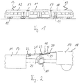
- eine Straßenbahn in Seitenansicht;
- Fig. 2:
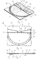
- eine schematische Darstellung eines erfindungsgemäßen Fahrzeuggelenkes in Seitenansicht;
- Fig. 3:
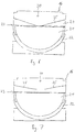
- eine erfindungsgemäße Übergangsplattform in perspektivischer Darstellung;
- Fig. 4:
- die Übergangsplattform aus
Fig. 3 in Draufsicht; - Fig. 5:
- einen Schnitt entlang der Linie R - R in
Fig. 4 ; und - Fig. 6 und 7:
- die Ansicht aus
Fig. 4 bei anderen Ausführungsformen der Erfindung.
- Fig. 1:
- a tram in side view;
- Fig. 2:
- a schematic representation of a vehicle hinge according to the invention in side view;
- 3:
- an inventive transition platform in perspective view;
- 4:
- the transition platform
Fig. 3 in plan view; - Fig. 5:
- a section along the line R - R in
Fig. 4 ; and - 6 and 7:
- the view
Fig. 4 in other embodiments of the invention.
Eine Straßenbahn in
Der Vorderwagen 10 und der Hinterwagen 12 sind jeweils über ein in
Zwischen den Wagen bestehen Durchgänge, die die Passagiere auch während der Fahrt durchqueren können. Die Durchgänge sind mit Faltenbälgen 17 umgeben, durch die die Passagiere vor Umgebungseinflüssen geschützt werden.There are passages between the cars, which passengers can cross even while driving. The passages are surrounded by
In
Die Übergangsplattform 16 umfasst einen vorderen Teil, der als Anschlussplatte 20 bezeichnet wird, und einen hinteren Teil in Form einer Drehplatte 21. Die Anschlussplatte 20 und die Drehplatte 21 sind über ein in Querrichtung ausgerichtetes Scharnier 23 verbunden. Das Scharnier 23 ist über eine Stütze 24 auf dem Fahrzeuggelenk 15 abgestützt. Aufgrund der Stütze ist die Übergangsplattform 16 so belastbar, dass Passagiere auf ihr stehen können. Die Übergangsplattform 16 ist auf ihrer Oberseite mit einer Struktur versehen, um einem Ausrutschen der Passagiere entgegenzuwirken.The
Die Anschlussplatte 20 ist fest mit dem Vorderwagen 10 verbunden. Insbesondere ist eine Drehbewegung zwischen dem Vorderwagen 10 und der Anschlussplatte 20 ausgeschlossen, so dass die Anschlussplatte 20 immer in Verlängerung des Vorderwagens 10 liegt. Die Drehplatte 21 ist drehbar gegenüber dem Mittelwagen 11 gelagert. Wenn also die Straßenbahn in der Ebene um eine Kurve fährt und damit in dem Fahrzeuggelenk 15 eine Drehbewegung stattfindet, so dreht sich der Mittelwagen 11 um die Drehplatte 21 herum. Der hintere Abschluss der Drehplatte 21 hat dazu die Form eines Kreisbogens, der in einem mit dem Mittelwagen 11 verbundenen Drehlager 22 geführt ist. Das Drehlager 22 hat ebenfalls eine kreisbogenförmige Kontur, die an die Drehplatte 21 angepasst ist. Das Drehlager 22 umgreift den hinteren Abschluss der Drehplatte 21 von oben und von unten, so dass die Drehplatte 21 in vertikaler Richtung definiert geführt ist. Außer der Drehbewegung entlang der kreisbogenförmigen Kontur ist auch in Längsrichtung eine Relativbewegung zwischen der Drehplatte 21 und dem Drehlager 22 möglich.The
Die Relativbewegung in Längsrichtung zwischen der Drehplatte 21 und dem Drehlager 22 trägt dazu bei, Nickbewegungen zwischen den Fahrzeugen auszugleichen. Nickbewegungen in dem Fahrzeuggelenk 15 entstehen, wenn die Straßenbahn über eine Kuppe oder durch eine Senke fährt. In der Übergangsplattform 16 führt die Nickbewegung zu einem Einknicken entlang dem Scharnier 23. Die Drehplatte 21 und die Anschlussplatte 20 stehen dann unter einem Winkel zueinander. Zusätzlich verschiebt sich die Drehplatte 21 in dem Drehlager 22 in Längsrichtung, um die mit der Knickbewegung verbundene Abstandsänderung zwischen dem Boden 18 des Vorderwagens 10 und dem Boden 19 des Mittelwagens 11 auszugleichen.The relative movement in the longitudinal direction between the
Die Drehbewegung, wenn die Straßenbahn um eine Kurve fährt, findet in der horizontalen Ebene statt (die Achse der Drehbewegung ist also senkrecht). Wenn das Drehlager 22 sich in einer horizontalen Ebene relativ zu der Übergangsplattform 16 bewegt, kann die Übergangsplattform 16 diese Bewegung aufgrund seiner Neigung in Längsrichtung nur durch eine Verwindung aufnehmen. Die Verwindung verstärkt sich gegebenenfalls, wenn gleichzeitig mit der Drehbewegung eine Wankbewegung zwischen den Wagen 10, 11 stattfindet, also eine Relativbewegung um die horizontale Längsachse. Die erfindungsgemäße Übergangsplattform 16 ist so gestaltet, dass sie die Verwindung in vorteilhafter Weise aufnehmen kann.The rotational movement when the tram turns around takes place in the horizontal plane (the axis of rotation is therefore vertical). When the pivot bearing 22 moves in a horizontal plane relative to the
Dazu besteht zunächst die Drehplatte 21 aus einem halbsteifen Material. Die Drehplatte 21 ist also einerseits stabil genug, dass Personen auf ihr stehen können. Andererseits ist die Drehplatte 21 so flexibel, dass sie einen Teil der von der Übergangsplattform 16 aufzunehmenden Verwindung ausgleichen kann. Wenn also das Drehlager 22 sich in einer horizontalen Ebene relativ zu der Drehplatte 21 bewegt, so führt dies dazu, dass die hintere Abschlusskante der Drehplatte 21 nicht mehr parallel zu dem Scharnier 23 ist, sondern um eine Längsachse verschwenkt ist.For this purpose, first there is the
Welches Material halbsteif im Sinne der Erfindung ist, hängt von der Auslegung der Übergangsplattform ab und muss deswegen bei der Konstruktion der Übergangsplattform jeweils geeignet ausgewählt werden. Hat die Übergangsplattform beispielsweise eine Gesamtlänge von ungefähr 120 cm und eine Gesamtbreite von ungefähr 150 cm, so kommt als halbsteifes Material für die Drehplatte eine Platte mit einer Stärke von 8 mm aus einer gängigen Aluminiumlegierung in Betracht.Which material is semi-rigid in the sense of the invention depends on the design of the transition platform and must therefore be suitably selected in the construction of the transition platform. For example, if the transfer platform has a total length of about 120 cm and a total width of about 150 cm, the semi-rigid material for the turntable may be a plate of 8 mm thickness made of a common aluminum alloy.
Außerdem sind, wie die
Unterhalb des Plattenausschnitts 29 ist ein in
An der Fuge 25 besteht kein Abstand zwischen dem Plattenausschnitt 29 und der Hauptplatte 32, sondern die beiden Teile liegen bei ebener Übergangsplattform 16 direkt aneinander an. Damit besteht ein Anschlag 35, der die Bewegungsfreiheit zwischen dem Plattenausschnitt 29 und der Hauptplatte 32 einschränkt. Betrachtet man die
Die Anschlussplatte 20 besteht in diesem Ausführungsbeispiel aus demselben halbsteifen Material wie die Drehplatte 21. Um zu verhindern, dass sich die Anschlussplatte 20 im Bereich der Fuge 25 verwindet, ist unterhalb der Anschlussplatte 20 parallel zum ersten Abschnitt 27 der Fuge 25 eine Verstärkungsleiste 33 angebracht.In this embodiment, the
Verwindet sich nun die Übergangsplattform 16 aufgrund einer Drehbewegung in dem Fahrzeuggelenk 15, so wird wie oben dargelegt ein Teil der Verwindung von der halbsteifen Drehplatte 21 aufgenommen. In der Anschlussplatte 20 führen die Verwindungskräfte dazu, dass die Anschlussplatte 20 entlang der einen Fuge 25 nach oben und entlang der anderen Fuge 25 nach unten einknicken möchte. Das Einknicken nach oben wird wie dargelegt durch den Anschlag 35 verhindert. Es findet also lediglich auf der anderen Seite ein Einknicken nach unten statt. Mit der Kombination aus einer Verwindung in der Drehplatte 21 und dem Einknicken entlang der Fuge 25 kann die Übergangsplattform 16 alle im Betrieb der Straßenbahn auftretenden Verwindungen aufnehmen. Durch die erfindungsgemäße Fugenverbindung wird dies möglich, ohne dass zwischen den Komponenten der Übergangsplattform 16 ein Ausgleich in Höhenrichtung oder in Längsrichtung erforderlich wäre. Die Verwindungen können von der Übergangsplattform 16 also aufgenommen werden, ohne dass Absätze oder Spalten auftreten, an denen die Passagiere stolpern könnten.Now, if the
Die
Claims (13)
- Bridging platform which is intended to be arranged above a vehicle articulation (15) with an inclination in the longitudinal direction, comprising a rotary plate (21) composed of a semirigid material, and a connection plate (20), wherein the rotary plate (21) and the connection plate (20) are connected to each other by a hinge (23) oriented in the transverse direction, wherein the connection plate (20) has a joint (25) which extends from the lateral edge in the direction of a centre axis (26) and defines a region of the connection plate, in which the connection plate can easily be buckled, with a distortion-resistant joint connection.
- Bridging platform according to Claim 1, characterized in that the joint connection is formed by a spring sheet (30).
- Bridging platform according to Claim 1 or 2, characterized in that the joint connection has a stop (35) which is effective against sagging.
- Bridging platform according to one of Claims 1 to 3, characterized in that the connection plate (20) has a reinforcing strip (33) which extends parallel to the joint (25).
- Bridging platform according to one of Claims 1 to 4, characterized in that the joint (25) has a portion which extends rectilinearly from the edge of the connection plate in the direction of the centre axis (26).
- Bridging platform according to one of Claims 1 to 5, characterized in that a plate section (29) is separated from a main part (32) in the connection plate (20) by the joint (25).
- Bridging platform according to Claim 6, characterized in that the joint (25) has a second portion (28) which is oriented substantially parallel to the centre axis (26) and which extends as far as the hinge (23).
- Bridging platform according to Claim 7, characterized in that the fastening (31) between the connection plate (20) and the joint connection is spaced apart from the joint (25) in the second portion (28) of the joint (25).
- Vehicle articulation system with a vehicle articulation (15) arranged between two coaches (10, 11, 12) of a vehicle, and with a bridging platform (16) arranged above the vehicle articulation (15), wherein the bridging platform (16) is inclined in the longitudinal direction, characterized in that the bridging platform is designed according to one of Claims 1 to 8.
- Vehicle articulation system according to Claim 9, characterized in that the connection plate (20) is connected to a first coach (10) for rotation therewith, and in that the rotary plate (21) is connected to a second coach via a rotary bearing (22) .
- Vehicle articulation system according to Claim 9 or 10, characterized in that the bridging platform (16) is supported on the vehicle articulation (15).
- Vehicle articulation system according to one of Claims 9 to 11, characterized in that displacement in the longitudinal direction between the rotary plate (21) and the rotary bearing (22) is possible.
- Vehicle articulation system according to one of Claims 9 to 12, characterized in that the connection plate and the rotary plate are located in a plane when the vehicle is in the normal state.
Priority Applications (3)
| Application Number | Priority Date | Filing Date | Title |
|---|---|---|---|
| DK10005948.4T DK2394877T3 (en) | 2010-06-09 | 2010-06-09 | Transition platform for a vehicle link |
| EP10005948.4A EP2394877B1 (en) | 2010-06-09 | 2010-06-09 | Bridging platform for a vehicle joint |
| PL10005948T PL2394877T3 (en) | 2010-06-09 | 2010-06-09 | Bridging platform for a vehicle joint |
Applications Claiming Priority (1)
| Application Number | Priority Date | Filing Date | Title |
|---|---|---|---|
| EP10005948.4A EP2394877B1 (en) | 2010-06-09 | 2010-06-09 | Bridging platform for a vehicle joint |
Publications (2)
| Publication Number | Publication Date |
|---|---|
| EP2394877A1 EP2394877A1 (en) | 2011-12-14 |
| EP2394877B1 true EP2394877B1 (en) | 2018-10-17 |
Family
ID=43033000
Family Applications (1)
| Application Number | Title | Priority Date | Filing Date |
|---|---|---|---|
| EP10005948.4A Active EP2394877B1 (en) | 2010-06-09 | 2010-06-09 | Bridging platform for a vehicle joint |
Country Status (3)
| Country | Link |
|---|---|
| EP (1) | EP2394877B1 (en) |
| DK (1) | DK2394877T3 (en) |
| PL (1) | PL2394877T3 (en) |
Families Citing this family (5)
| Publication number | Priority date | Publication date | Assignee | Title |
|---|---|---|---|---|
| DE102013218547B3 (en) * | 2013-09-16 | 2015-02-05 | Bombardier Transportation Gmbh | Transitional platform with torsion zones, vehicle hinge system and rail vehicle |
| DE102015214475A1 (en) * | 2015-07-30 | 2017-02-02 | Siemens Aktiengesellschaft | Covering device for covering a floor gap and vehicle with such a covering device |
| EP3225433B1 (en) * | 2016-03-30 | 2018-07-18 | Hübner GmbH & Co. KG | Connection assembly between two vehicle parts of a rail vehicle |
| AT16242U1 (en) * | 2017-12-21 | 2019-05-15 | Huebner Gmbh & Co Kg | Walk-in ground facility for a transition |
| CN110254454B (en) * | 2019-07-08 | 2020-09-22 | 中车株洲电力机车有限公司 | Tramcar and through passage floor thereof |
Family Cites Families (5)
| Publication number | Priority date | Publication date | Assignee | Title |
|---|---|---|---|---|
| FR2611634B2 (en) * | 1986-03-28 | 1989-05-12 | Caoutchouc Manuf Plastique | IMPROVEMENT TO A DEVICE FOR ENSURING THE CONTINUITY OF PASSAGE BETWEEN TWO SUCCESSIVE VEHICLES, RAILWAYS OR ROADS |
| DE4138921A1 (en) * | 1991-11-27 | 1993-06-03 | Huebner Gummi & Kunststoff | Disc shaped platform between two parts of omnibus - has shelf support which is elastically deformable in vertical direction |
| DE4329674B4 (en) * | 1993-09-02 | 2004-08-12 | Hübner GmbH | Gap formation between the transition platform and the floors of the front and rear of articulated vehicles, in particular street articulated buses |
| DE9413285U1 (en) | 1994-08-17 | 1995-06-08 | Aeg Schienenfahrzeuge | Turntable for the crossing of rail vehicles |
| DE202006007377U1 (en) | 2006-05-09 | 2006-07-20 | Hübner GmbH | Bridge with turntable for creation of articulated bus or tram, comprising turntable arranged in inclined position above movable joint |
-
2010
- 2010-06-09 DK DK10005948.4T patent/DK2394877T3/en active
- 2010-06-09 EP EP10005948.4A patent/EP2394877B1/en active Active
- 2010-06-09 PL PL10005948T patent/PL2394877T3/en unknown
Non-Patent Citations (1)
| Title |
|---|
| None * |
Also Published As
| Publication number | Publication date |
|---|---|
| DK2394877T3 (en) | 2019-02-11 |
| EP2394877A1 (en) | 2011-12-14 |
| PL2394877T3 (en) | 2019-03-29 |
Similar Documents
| Publication | Publication Date | Title |
|---|---|---|
| EP2394877B1 (en) | Bridging platform for a vehicle joint | |
| EP2384913B1 (en) | Bracket system for an articulated vehicle | |
| DE102009034511A1 (en) | Device for connecting a table to the side wall of a vehicle | |
| WO2016174135A1 (en) | Linkage for the articulated connection of a vehicle-body-side end region of a coupling rod to a vehicle body | |
| DE102009004525B4 (en) | Safety gear for a wheelchair in a vehicle, in particular rail vehicle | |
| EP3345804A1 (en) | Roof joint for an articulated vehicle | |
| EP2157006B1 (en) | Bridge for a communication passage between two articulated vehicles, e.g. of a tramway | |
| DE202013100563U1 (en) | Bridge between two articulated vehicle parts | |
| EP2412600B1 (en) | Roof joint for an articulated vehicle | |
| EP0983931B1 (en) | Connection between two articulated vehicle parts | |
| DE10021967A1 (en) | Device for the articulated connection of car bodies of a multi-unit rail vehicle | |
| DE102013218547B3 (en) | Transitional platform with torsion zones, vehicle hinge system and rail vehicle | |
| EP3081450B1 (en) | Transport vehicle | |
| DE102014220775B4 (en) | Rail vehicle in semi-trailer design | |
| DE19544169A1 (en) | Seat height adjuster with front and rear adjustment elements | |
| EP2594450B1 (en) | Intersection half between two loose jointed vehicles of a rail car | |
| WO2016165822A1 (en) | Connecting device, conveying carriage and conveying installation | |
| DE10044851A1 (en) | Car seat has frame whose position can be adjusted using spindle nut which moves along spindle with profiled plate which prevents spindle from bending in crash, plate being attached to seat frame and acting as guide for motion of nut | |
| EP2308736B1 (en) | Interior gaiter wall lining for the intersection of two vehicles with a jointed connection or vehicle parts | |
| EP3265359B1 (en) | Swivel joint for swivel-joint connecting of rail vehicles | |
| WO1993008061A1 (en) | Flexible weatherproof gangway between two goods-wagon units with height-adjustable roofs | |
| DE102010050005A1 (en) | Connector for connecting e.g. bridge plate and base plate of rail vehicle, has lips for covering upper-sides of edge areas of elements, where connector comprises material provided in region of recess and in other regions of another material | |
| DE102018131851B3 (en) | Bumper assembly for a motor vehicle | |
| EP3501863B1 (en) | Accessible floor device for a transition | |
| DE20312575U1 (en) | Floor arrangement for articulated vehicles has first floor plate section rigidly connected to front car of vehicle to cover region of articulated joint through rotational axis and through pitch axis in direction of rear car |
Legal Events
| Date | Code | Title | Description |
|---|---|---|---|
| AK | Designated contracting states |
Kind code of ref document: A1 Designated state(s): AL AT BE BG CH CY CZ DE DK EE ES FI FR GB GR HR HU IE IS IT LI LT LU LV MC MK MT NL NO PL PT RO SE SI SK SM TR |
|
| AX | Request for extension of the european patent |
Extension state: BA ME RS |
|
| PUAI | Public reference made under article 153(3) epc to a published international application that has entered the european phase |
Free format text: ORIGINAL CODE: 0009012 |
|
| 17P | Request for examination filed |
Effective date: 20120323 |
|
| 17Q | First examination report despatched |
Effective date: 20140117 |
|
| STAA | Information on the status of an ep patent application or granted ep patent |
Free format text: STATUS: EXAMINATION IS IN PROGRESS |
|
| GRAP | Despatch of communication of intention to grant a patent |
Free format text: ORIGINAL CODE: EPIDOSNIGR1 |
|
| STAA | Information on the status of an ep patent application or granted ep patent |
Free format text: STATUS: GRANT OF PATENT IS INTENDED |
|
| INTG | Intention to grant announced |
Effective date: 20180516 |
|
| GRAS | Grant fee paid |
Free format text: ORIGINAL CODE: EPIDOSNIGR3 |
|
| GRAA | (expected) grant |
Free format text: ORIGINAL CODE: 0009210 |
|
| STAA | Information on the status of an ep patent application or granted ep patent |
Free format text: STATUS: THE PATENT HAS BEEN GRANTED |
|
| AK | Designated contracting states |
Kind code of ref document: B1 Designated state(s): AL AT BE BG CH CY CZ DE DK EE ES FI FR GB GR HR HU IE IS IT LI LT LU LV MC MK MT NL NO PL PT RO SE SI SK SM TR |
|
| REG | Reference to a national code |
Ref country code: GB Ref legal event code: FG4D Free format text: NOT ENGLISH |
|
| REG | Reference to a national code |
Ref country code: CH Ref legal event code: EP |
|
| REG | Reference to a national code |
Ref country code: IE Ref legal event code: FG4D Free format text: LANGUAGE OF EP DOCUMENT: GERMAN |
|
| REG | Reference to a national code |
Ref country code: DE Ref legal event code: R096 Ref document number: 502010015458 Country of ref document: DE Ref country code: AT Ref legal event code: REF Ref document number: 1053636 Country of ref document: AT Kind code of ref document: T Effective date: 20181115 |
|
| REG | Reference to a national code |
Ref country code: CH Ref legal event code: NV Representative=s name: DENNEMEYER AG, CH |
|
| REG | Reference to a national code |
Ref country code: DK Ref legal event code: T3 Effective date: 20190207 |
|
| REG | Reference to a national code |
Ref country code: NL Ref legal event code: MP Effective date: 20181017 |
|
| REG | Reference to a national code |
Ref country code: LT Ref legal event code: MG4D |
|
| PG25 | Lapsed in a contracting state [announced via postgrant information from national office to epo] |
Ref country code: NL Free format text: LAPSE BECAUSE OF FAILURE TO SUBMIT A TRANSLATION OF THE DESCRIPTION OR TO PAY THE FEE WITHIN THE PRESCRIBED TIME-LIMIT Effective date: 20181017 |
|
| PG25 | Lapsed in a contracting state [announced via postgrant information from national office to epo] |
Ref country code: FI Free format text: LAPSE BECAUSE OF FAILURE TO SUBMIT A TRANSLATION OF THE DESCRIPTION OR TO PAY THE FEE WITHIN THE PRESCRIBED TIME-LIMIT Effective date: 20181017 Ref country code: LT Free format text: LAPSE BECAUSE OF FAILURE TO SUBMIT A TRANSLATION OF THE DESCRIPTION OR TO PAY THE FEE WITHIN THE PRESCRIBED TIME-LIMIT Effective date: 20181017 Ref country code: NO Free format text: LAPSE BECAUSE OF FAILURE TO SUBMIT A TRANSLATION OF THE DESCRIPTION OR TO PAY THE FEE WITHIN THE PRESCRIBED TIME-LIMIT Effective date: 20190117 Ref country code: IS Free format text: LAPSE BECAUSE OF FAILURE TO SUBMIT A TRANSLATION OF THE DESCRIPTION OR TO PAY THE FEE WITHIN THE PRESCRIBED TIME-LIMIT Effective date: 20190217 Ref country code: LV Free format text: LAPSE BECAUSE OF FAILURE TO SUBMIT A TRANSLATION OF THE DESCRIPTION OR TO PAY THE FEE WITHIN THE PRESCRIBED TIME-LIMIT Effective date: 20181017 Ref country code: HR Free format text: LAPSE BECAUSE OF FAILURE TO SUBMIT A TRANSLATION OF THE DESCRIPTION OR TO PAY THE FEE WITHIN THE PRESCRIBED TIME-LIMIT Effective date: 20181017 Ref country code: ES Free format text: LAPSE BECAUSE OF FAILURE TO SUBMIT A TRANSLATION OF THE DESCRIPTION OR TO PAY THE FEE WITHIN THE PRESCRIBED TIME-LIMIT Effective date: 20181017 Ref country code: BG Free format text: LAPSE BECAUSE OF FAILURE TO SUBMIT A TRANSLATION OF THE DESCRIPTION OR TO PAY THE FEE WITHIN THE PRESCRIBED TIME-LIMIT Effective date: 20190117 |
|
| PG25 | Lapsed in a contracting state [announced via postgrant information from national office to epo] |
Ref country code: AL Free format text: LAPSE BECAUSE OF FAILURE TO SUBMIT A TRANSLATION OF THE DESCRIPTION OR TO PAY THE FEE WITHIN THE PRESCRIBED TIME-LIMIT Effective date: 20181017 Ref country code: SE Free format text: LAPSE BECAUSE OF FAILURE TO SUBMIT A TRANSLATION OF THE DESCRIPTION OR TO PAY THE FEE WITHIN THE PRESCRIBED TIME-LIMIT Effective date: 20181017 Ref country code: PT Free format text: LAPSE BECAUSE OF FAILURE TO SUBMIT A TRANSLATION OF THE DESCRIPTION OR TO PAY THE FEE WITHIN THE PRESCRIBED TIME-LIMIT Effective date: 20190217 Ref country code: GR Free format text: LAPSE BECAUSE OF FAILURE TO SUBMIT A TRANSLATION OF THE DESCRIPTION OR TO PAY THE FEE WITHIN THE PRESCRIBED TIME-LIMIT Effective date: 20190118 |
|
| REG | Reference to a national code |
Ref country code: DE Ref legal event code: R097 Ref document number: 502010015458 Country of ref document: DE |
|
| PLBE | No opposition filed within time limit |
Free format text: ORIGINAL CODE: 0009261 |
|
| STAA | Information on the status of an ep patent application or granted ep patent |
Free format text: STATUS: NO OPPOSITION FILED WITHIN TIME LIMIT |
|
| PG25 | Lapsed in a contracting state [announced via postgrant information from national office to epo] |
Ref country code: SK Free format text: LAPSE BECAUSE OF FAILURE TO SUBMIT A TRANSLATION OF THE DESCRIPTION OR TO PAY THE FEE WITHIN THE PRESCRIBED TIME-LIMIT Effective date: 20181017 Ref country code: RO Free format text: LAPSE BECAUSE OF FAILURE TO SUBMIT A TRANSLATION OF THE DESCRIPTION OR TO PAY THE FEE WITHIN THE PRESCRIBED TIME-LIMIT Effective date: 20181017 Ref country code: SM Free format text: LAPSE BECAUSE OF FAILURE TO SUBMIT A TRANSLATION OF THE DESCRIPTION OR TO PAY THE FEE WITHIN THE PRESCRIBED TIME-LIMIT Effective date: 20181017 Ref country code: EE Free format text: LAPSE BECAUSE OF FAILURE TO SUBMIT A TRANSLATION OF THE DESCRIPTION OR TO PAY THE FEE WITHIN THE PRESCRIBED TIME-LIMIT Effective date: 20181017 |
|
| 26N | No opposition filed |
Effective date: 20190718 |
|
| PG25 | Lapsed in a contracting state [announced via postgrant information from national office to epo] |
Ref country code: SI Free format text: LAPSE BECAUSE OF FAILURE TO SUBMIT A TRANSLATION OF THE DESCRIPTION OR TO PAY THE FEE WITHIN THE PRESCRIBED TIME-LIMIT Effective date: 20181017 |
|
| PG25 | Lapsed in a contracting state [announced via postgrant information from national office to epo] |
Ref country code: MC Free format text: LAPSE BECAUSE OF FAILURE TO SUBMIT A TRANSLATION OF THE DESCRIPTION OR TO PAY THE FEE WITHIN THE PRESCRIBED TIME-LIMIT Effective date: 20181017 |
|
| GBPC | Gb: european patent ceased through non-payment of renewal fee |
Effective date: 20190609 |
|
| REG | Reference to a national code |
Ref country code: BE Ref legal event code: MM Effective date: 20190630 |
|
| PG25 | Lapsed in a contracting state [announced via postgrant information from national office to epo] |
Ref country code: GB Free format text: LAPSE BECAUSE OF NON-PAYMENT OF DUE FEES Effective date: 20190609 Ref country code: IE Free format text: LAPSE BECAUSE OF NON-PAYMENT OF DUE FEES Effective date: 20190609 |
|
| PG25 | Lapsed in a contracting state [announced via postgrant information from national office to epo] |
Ref country code: BE Free format text: LAPSE BECAUSE OF NON-PAYMENT OF DUE FEES Effective date: 20190630 Ref country code: LU Free format text: LAPSE BECAUSE OF NON-PAYMENT OF DUE FEES Effective date: 20190609 |
|
| PG25 | Lapsed in a contracting state [announced via postgrant information from national office to epo] |
Ref country code: CY Free format text: LAPSE BECAUSE OF FAILURE TO SUBMIT A TRANSLATION OF THE DESCRIPTION OR TO PAY THE FEE WITHIN THE PRESCRIBED TIME-LIMIT Effective date: 20181017 |
|
| PG25 | Lapsed in a contracting state [announced via postgrant information from national office to epo] |
Ref country code: MT Free format text: LAPSE BECAUSE OF FAILURE TO SUBMIT A TRANSLATION OF THE DESCRIPTION OR TO PAY THE FEE WITHIN THE PRESCRIBED TIME-LIMIT Effective date: 20181017 Ref country code: HU Free format text: LAPSE BECAUSE OF FAILURE TO SUBMIT A TRANSLATION OF THE DESCRIPTION OR TO PAY THE FEE WITHIN THE PRESCRIBED TIME-LIMIT; INVALID AB INITIO Effective date: 20100609 |
|
| PG25 | Lapsed in a contracting state [announced via postgrant information from national office to epo] |
Ref country code: MK Free format text: LAPSE BECAUSE OF FAILURE TO SUBMIT A TRANSLATION OF THE DESCRIPTION OR TO PAY THE FEE WITHIN THE PRESCRIBED TIME-LIMIT Effective date: 20181017 |
|
| PGFP | Annual fee paid to national office [announced via postgrant information from national office to epo] |
Ref country code: FR Payment date: 20230621 Year of fee payment: 14 Ref country code: DK Payment date: 20230621 Year of fee payment: 14 Ref country code: DE Payment date: 20230620 Year of fee payment: 14 Ref country code: CZ Payment date: 20230531 Year of fee payment: 14 |
|
| PGFP | Annual fee paid to national office [announced via postgrant information from national office to epo] |
Ref country code: TR Payment date: 20230602 Year of fee payment: 14 Ref country code: PL Payment date: 20230531 Year of fee payment: 14 Ref country code: AT Payment date: 20230616 Year of fee payment: 14 |
|
| PGFP | Annual fee paid to national office [announced via postgrant information from national office to epo] |
Ref country code: IT Payment date: 20230630 Year of fee payment: 14 Ref country code: CH Payment date: 20230702 Year of fee payment: 14 |