EP2391775B1 - Bauelement und solche elemente verwendende stützwand - Google Patents
Bauelement und solche elemente verwendende stützwand Download PDFInfo
- Publication number
- EP2391775B1 EP2391775B1 EP10701673A EP10701673A EP2391775B1 EP 2391775 B1 EP2391775 B1 EP 2391775B1 EP 10701673 A EP10701673 A EP 10701673A EP 10701673 A EP10701673 A EP 10701673A EP 2391775 B1 EP2391775 B1 EP 2391775B1
- Authority
- EP
- European Patent Office
- Prior art keywords
- face
- construction
- wall
- lug
- component
- Prior art date
- Legal status (The legal status is an assumption and is not a legal conclusion. Google has not performed a legal analysis and makes no representation as to the accuracy of the status listed.)
- Active
Links
- 238000010276 construction Methods 0.000 title claims description 90
- 230000000295 complement effect Effects 0.000 description 4
- 230000015572 biosynthetic process Effects 0.000 description 3
- 238000006073 displacement reaction Methods 0.000 description 3
- 210000000078 claw Anatomy 0.000 description 2
- 230000000903 blocking effect Effects 0.000 description 1
- 230000006866 deterioration Effects 0.000 description 1
- 230000000694 effects Effects 0.000 description 1
- 238000004519 manufacturing process Methods 0.000 description 1
- 239000000463 material Substances 0.000 description 1
- 238000000034 method Methods 0.000 description 1
- 238000009877 rendering Methods 0.000 description 1
- 239000011435 rock Substances 0.000 description 1
- 230000035939 shock Effects 0.000 description 1
- 230000006641 stabilisation Effects 0.000 description 1
- 238000011105 stabilization Methods 0.000 description 1
- 239000002023 wood Substances 0.000 description 1
Images


Classifications
-
- E—FIXED CONSTRUCTIONS
- E02—HYDRAULIC ENGINEERING; FOUNDATIONS; SOIL SHIFTING
- E02D—FOUNDATIONS; EXCAVATIONS; EMBANKMENTS; UNDERGROUND OR UNDERWATER STRUCTURES
- E02D29/00—Independent underground or underwater structures; Retaining walls
- E02D29/02—Retaining or protecting walls
- E02D29/025—Retaining or protecting walls made up of similar modular elements stacked without mortar
-
- A—HUMAN NECESSITIES
- A01—AGRICULTURE; FORESTRY; ANIMAL HUSBANDRY; HUNTING; TRAPPING; FISHING
- A01G—HORTICULTURE; CULTIVATION OF VEGETABLES, FLOWERS, RICE, FRUIT, VINES, HOPS OR SEAWEED; FORESTRY; WATERING
- A01G9/00—Cultivation in receptacles, forcing-frames or greenhouses; Edging for beds, lawn or the like
- A01G9/02—Receptacles, e.g. flower-pots or boxes; Glasses for cultivating flowers
- A01G9/022—Pots for vertical horticulture
- A01G9/025—Containers and elements for greening walls
-
- E—FIXED CONSTRUCTIONS
- E04—BUILDING
- E04C—STRUCTURAL ELEMENTS; BUILDING MATERIALS
- E04C1/00—Building elements of block or other shape for the construction of parts of buildings
- E04C1/39—Building elements of block or other shape for the construction of parts of buildings characterised by special adaptations, e.g. serving for locating conduits, for forming soffits, cornices, or shelves, for fixing wall-plates or door-frames, for claustra
- E04C1/395—Building elements of block or other shape for the construction of parts of buildings characterised by special adaptations, e.g. serving for locating conduits, for forming soffits, cornices, or shelves, for fixing wall-plates or door-frames, for claustra for claustra, fences, planting walls, e.g. sound-absorbing
-
- Y—GENERAL TAGGING OF NEW TECHNOLOGICAL DEVELOPMENTS; GENERAL TAGGING OF CROSS-SECTIONAL TECHNOLOGIES SPANNING OVER SEVERAL SECTIONS OF THE IPC; TECHNICAL SUBJECTS COVERED BY FORMER USPC CROSS-REFERENCE ART COLLECTIONS [XRACs] AND DIGESTS
- Y02—TECHNOLOGIES OR APPLICATIONS FOR MITIGATION OR ADAPTATION AGAINST CLIMATE CHANGE
- Y02P—CLIMATE CHANGE MITIGATION TECHNOLOGIES IN THE PRODUCTION OR PROCESSING OF GOODS
- Y02P60/00—Technologies relating to agriculture, livestock or agroalimentary industries
- Y02P60/20—Reduction of greenhouse gas [GHG] emissions in agriculture, e.g. CO2
Definitions
- the present invention relates to a building element, in particular concrete, for producing retaining walls.
- each construction element is intended to cooperate in superposition with at least one similar construction element.
- Each building element comprises a top face, a bottom face, a front face and a rear face and at least two elongate section cavities opening on the top face and the bottom face, these two cells being substantially parallel aligned on the back side.
- Each building element has on its underside at least one central projection and a projecting rib.
- the central projection is intended to engage in one of the rear cavities of a lower level building element. While the protruding rib is intended to abut along the upper edge of the rear face of a lower level building element, contributing to the wedging of the two elements in the transverse direction.
- This type of construction element thus has the disadvantage of being unstable when superposed on the right for storage and particularly in the form of pallets.
- superimposed on the right is meant that the building elements are stacked on top of one another with no offset so as to exactly match.
- the building elements as previously described according to the state of the art allow a rotation of the building elements relative to each other so as to form retaining walls having a certain curvature. Therefore, it is necessary to maintain this characteristic and allow the rotation of the building elements relative to each other.
- the present invention provides building elements of the aforementioned type that allow a fast and efficient storage while allowing to make a retaining wall may have a certain curvature.
- the construction element intended to cooperate in superposition with at least one similar element of construction, each of the elements comprising a top face, a bottom face, a front face and a rear face and at least two cells of elongate section opening on the top face and the bottom face, these two cells being aligned substantially parallel to the rear face.
- the construction element having on its underside a central projection engageable with clearance in one of said elongated section cells of a lower or higher level building element and a projecting rib which extends parallel to the rear face in extension of the inner wall of one of the cells of a building element of lower or higher level.
- the construction element according to the invention comprises at least one clutch contiguous to the inner wall of the front face over its entire height and projecting on the underside.
- a dog means a relief such as a projection, a rib, a boss which is intended to cooperate with another element.
- the clutch of the element according to the invention is preferably constructed of the same material as the rest of the construction element.
- the superposition of the construction elements during storage no longer requires adding additional element such as a wedge since the protrusion protruding from the underside of an element abuts on the face of above the lower construction element limiting any tilting.
- the clutch of the element according to the invention extends beyond the plane of the bottom face and over the entire height of the front face to stop at the plane of the plane. the face from above.
- the clutch of the element according to the invention does not limit the construction of retaining walls with a strong curvature. Indeed because of its configuration the dog can be easily removed so as to obtain a construction element for a significant curvature.
- the construction element according to the invention further comprises at least two cavities opening on the top face and the bottom face and disposed at the front face.
- each of the cavities comprises a clutch as described. .
- the clutch of the element according to the invention engages playfully in one of the cavities of a lower level building element and abuts between the inner wall of the front face and the outer wall of the rear cells of the lower level building element.
- the clutch of the element according to the invention has the advantage of reducing the longitudinal play of the building elements relative to each other during assembly.
- the positioning of the levels of the retaining wall is facilitated.
- the laying speed is increased.
- the technical efficiency and the aesthetic rendering of the retaining wall are improved ...
- the half-element is such that it comprises a clutch attached to the inner wall of the front face over its entire height projecting on the underside.
- the invention relates to a retaining wall comprising several levels of building elements as described above.
- the retaining wall according to the invention is formed of levels of construction elements offset relative to one another corresponding to the length of a half-element of construction described above.
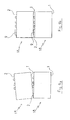
- Each of the building elements comprises a top face 1, a bottom face 2, a front face 3 and a rear face 4 and at least two cells 5, 6 of elongated section and opening on the top face 1 and on the face 2. These two cells 5, 6 are aligned substantially parallel to the rear face 4.
- each construction element comprises (see Figures 1 to 3 ) on its underside 2 in a central region thereof a central projection 7, for example of rectangular section that can engage with clearance in one of said recesses 5, 6 of elongated section of a construction element as represented in figure 8 .
- the construction element further comprises a first protruding rib 8 which extends parallel to the rear face 4 of the element in extension of the inner wall of one of the cavities 5, 6 .
- the construction element comprises on its underside 2 at least one clutch 9 attached to the inner wall 10 of the front face 3 over its entire height.
- This clutch 9 has several functions. First, because it extends over the entire height of the inner wall 10 of the front face 3, it allows restore the balance of the building element when it is superimposed on the right with other similar building elements for storage and transport by pallet.
- the clutch 9 has a relief above the plane of the bottom face 2. According to a preferred embodiment, the height of the claw 9 of the relief is substantially equivalent to the height of the other reliefs such as projections and ribs of the face of 2.
- the central projection 7 and the rib 8 are preferably of a height of about twenty millimeters.
- the reliefs or free surfaces such as the central projection 7, the rib 8 and the clutch 9 are defined in the same plane.
- the clutch 9 is located at the plane of the top face 1. It does not extend beyond the plane of the top face 1. Thus, when two building elements are superimposed on the right to be stored in the form of a pallet, the clutch 9 embossed at the bottom face 2 comes to rest on the clutch 9 at the plane of the top face 1 of a construction element of lower level.
- the reliefs or free surfaces of the bottom face 2 of a construction element such as the central projection 7, the rib 8 and the clutch 9 and the top face 1 of a second element of superimposed construction define complementary planes to achieve a stable overlay when the building elements are superimposed on the right.
- This clutch 9 also has a wedging role allowing controlled positioning of the building elements relative to each other during the construction of a retaining wall according to the invention.
- the central projection 7 engages in one of the rear cavities 5, 6 of a preferably lower level construction element thus limiting the longitudinal and transverse displacement of the upper construction element by relative to the lower building element.
- the rib 8 extends along the upper edge of the rear face 4 of the lower level building element, covering a portion of the length of this edge to stabilize the building element of higher level relative to the block of the lower level building element horizontally.
- the clutch 9 completes the blocking of the higher level building element relative to the lower level building element by limiting the longitudinal displacement of the building elements.
- the construction element according to the invention comprises at least two cavities 12, 13 opening on the top face 1 and the bottom face 2 and disposed at the front face 3.
- each of the cavities 12, 13 is disposed in alignment with the rear cavities 5, 6 at the front face 3.
- each of the cavities comprises a clutch 9.
- the clutch 9 is formed by an excess thickness extending over the entire height of the inner wall 10 of the front face 3. This excess thickness is preferably of the order of 10 to 12 millimeters.
- the different walls of the building element have a thickness of the order of 26 to 28 millimeters.
- This arrangement of the clutch 9 by extra thickness facilitates the breakage of the clutch 9 protruding beyond the plane of the bottom face 2, so as to obtain a building element according to the state of the art for the formation of walls of support with strong curvatures.
- This clutch 9 is easily broken with a hammer or other mass tool by a single stroke. Due to the formation of the protrusion by an excess thickness over the entire height of the wall, there is no risk of damage to the construction element when the claw 9 breaks.
- the clutch 9 breaks preferentially along a line of rupture substantially contained in the plane of the bottom face 2.
- the plane of the bottom face 2 contains the lower ends of the wall of the building element 18.
- the clutch 9 When superimposing building elements for the formation of retaining wall as shown in figure 8 , the clutch 9 abuts against the inner wall 10 of the front face 3 and against the outer wall 5b or 6b of one of the rear cavities 5, 6 of a lower level building element.
- the clutch 9 preferably formed by an extra thickness has a substantially rectangular shape.
- the clutch 9 has a length of between 50 and 150 millimeters.
- the bottom face 2 of the construction element comprises a second projecting rib 11 which extends in the extension of a part of the rear face 4 of the construction element 18.
- Each of the ribs 8, 11 extends from one end of the building element to a point beyond the middle of the element.
- the clearance between the central projection 7 and the inner walls 5a, 6a of one of the cells 5, 6 is such that it allows some rotation between two building elements of upper and lower level. This rotation is limited by the abutment formed between the first rib 8 of the upper level building element and the upper edge of the rear face 4 of the lower level element.
- FIGS. 1 to 3 show on the other hand that the central projection 7 is formed on the bottom face 2 of a wall separating the two cavities 12, 13 distinct from the elongated cells 5, 6.
- the front face 3 is formed by two end walls 14, 15 of circular section forming the cavities 12, 13.
- the outside of these end walls 14 , 15 is arranged with a sawtooth relief as shown in FIG. figures 1 , 2 , 5, 7 and 8 .
- the construction element comprises on one of its sides a complementary zone 16 designed to cooperate with the complementary side of a retaining wall. Similar building element. This arrangement also allows the realization of retaining wall with strong curvature.
- the figure 8 shows a portion of retaining wall in which the rows of building elements are offset relative to each other by a length which is adjustable along the length of the cell 5, 6 in which is engaged the part protruding 7 and the length of the clutch 9 of each of the cavities 12, 13.
- the offset is half a length of building elements.
- the retaining wall may comprise, at the ends of certain rows, construction half-elements 19a, 19b whose structure corresponds substantially to the cut of a building element as described above according to a plan. perpendicular to its length and passing through the middle of the central projection 7.
- Such half-building elements 19a, 19b are shown in FIGS. Figures 4 to 7 .
- These elements comprise only a cell 5 or 6, a cavity 12 or 13, the central projection 7 has a length equal to half that of a construction element 18.
- Ribs 8a and 11a are also present but their length is smaller.
- the half-element 19a, 19b shown on the figures 4 , 5, 6 is a half-element construction right, adapted to be placed at the right end of a row.
- the half-element 19b shown in figure 7 is a half-left element adapted to be placed at the left end of a row.
- These half-construction elements 19a, 19b similarly comprise the construction elements a clutch 9 at the cavity 12 or 13.
- One of the advantages of the construction elements provided with the clutch 9 according to the invention is to allow stabilization of the elements themselves without the need for additional element such as wedges. Indeed, the addition of wedges, including wood, does not provide sufficient security since there is a risk of mispositioning and therefore tilting of all the building elements superimposed. In addition, the positioning of shims is a manual act that significantly increases the time of palletizing. Finally, the cost is increased by the use of an additional element and the time required for palletizing.
- the construction element according to the invention makes it possible to reduce the cost of industrialization by avoiding the manual positioning of shims during manufacture, allowing easy palletization and easy storage.
- the construction element according to the invention prevents the tilting of the element on the front and allows a fast and regular setting.
Landscapes
- Engineering & Computer Science (AREA)
- Life Sciences & Earth Sciences (AREA)
- Architecture (AREA)
- Civil Engineering (AREA)
- Structural Engineering (AREA)
- Paleontology (AREA)
- General Life Sciences & Earth Sciences (AREA)
- Mining & Mineral Resources (AREA)
- Environmental & Geological Engineering (AREA)
- General Engineering & Computer Science (AREA)
- Environmental Sciences (AREA)
- Portable Nailing Machines And Staplers (AREA)
- Finishing Walls (AREA)
- Joining Of Building Structures In Genera (AREA)
- Organic Low-Molecular-Weight Compounds And Preparation Thereof (AREA)
- Fire-Extinguishing Compositions (AREA)
Claims (11)
- Konstruktionselement (18), bestimmt zum Zusammenwirken durch Übereinanderstellen mit mindestens einem gleichartigen Konstruktionselement, bestehend aus:■ einer Oberseite (1), einer Unterseite (2), einer Vorderseite (3) und einer Rückseite (4),■ mit mindestens zwei rückseitigen Ausnehmungen (5, 6) mit länglichem Querschnitt, die bezogen auf die Rückseite (4) annähernd parallel ausgerichtet und auf der Oberseite (1) und der Unterseite (2) offen sind,■ einer mittleren Überhöhung (7) im mittleren Bereich auf der Unterseite (2), die in eine der rückseitigen Ausnehmungen (5, 6) eines gleichartigen Konstruktionselementes (18) eingreifen kann,■ einer rippenförmigen Überhöhung (8) auf der Unterseite (2), die parallel zur Rückseite (4) in der Verlängerung der Innenwand (6a) einer der Ausnehmungen (5, 6) verläuft,so dass das Konstruktionselement (18) mindestens ein formschlüssiges Verbindungselement (9) besitzt, das an der Innenwand (5a) der Vorderseite (3) angesetzt ist und auf der Unterseite (2) hervorsteht,
gekennzeichnet dadurch, dass das formschlüssige Verbindungselement (9) an die Innenwand der Vorderseite (3) über deren gesamte Höhe angesetzt ist. - Konstruktionselement (18) gemäß Patentanspruch 1 mit mindestens zwei, an der Vorderseite (3) angeordneten Hohlräumen (12, 13), die auf der Oberseite (1) und der Unterseite (2) offen sind.
- Konstruktionselement (18) gemäß Patentanspruch 2, mit einem formschlüssigen Verbindungselement (9) in jedem der Hohlräume (12, 13).
- Konstruktionselement gemäß einem der vorstehenden Patentansprüche, bei dem das formschlüssige Verbindungselement (9) so gestaltet ist, das es bei einer schlagartigen Beanspruchung bricht, wobei die Bruchlinie annähernd in der Ebene der Unterseite (2) verläuft.
- Konstruktionselement (18) gemäß einem der vorstehenden Patentansprüche, bei dem das formschlüssige Verbindungselement aus einer Verdickung über die gesamte Höhe der Vorderseite (3) besteht.
- Konstruktionselement (18) gemäß Patentanspruch 2 bis 5, bei dem, wenn zwei gleichartige Konstruktionselemente übereinander gestellt werden, das formschlüssige Verbindungselement (9) der oberen Ebene mit Spiel in einen der Hohlräume (12, 13) des Konstruktionselements (18) der unteren Ebene eingreift.
- Konstruktionselement (18) gemäß einem der vorstehenden Patentansprüche, bei dem das formschlüssige Verbindungselement (9) eine Bewegung in Längsrichtung des genannten Elements dadurch begrenzt, dass es an der Innenwand (10) der Vorderseite (3) und an der Außenwand (6b) einer der rückseitigen Ausnehmungen (6) eines Konstruktionselements (18) der unteren Ebene zum Anschlag kommt.
- Konstruktionselement (18) gemäß einem der vorstehenden Patentansprüche, bei dem das formschlüssige Verbindungselement (9) eine annähernd rechteckige Form besitzt.
- Konstruktionselementhälfte (19a, 19b) bestehend aus:• einer Oberseite (1), einer Unterseite (2), einer Vorderseite (3) und einer Rückseite (4),• einer Ausnehmung (5, 6) mit länglichem Querschnitt, die annähernd parallel zur Rückseite (4) ausgerichtet und auf der Oberseite (1) und der Unterseite (2) offen ist,• einer Überhöhung (7) auf der Unterseite (2), die in eine rückseitige Ausnehmung (5, 6) eines Konstruktionselements gemäß einem der Patentansprüche 1 bis 8 oder einer gleichartigen Konstruktionselementhälfte eingreifen kann, sowie einer rippenförmigen Überhöhung (8), die parallel zur Rückseite in der Verlängerung der Innenwand der Ausnehmung verläuft,so dass sie ein formschlüssiges Verbindungselement (9) besitzt, das an der Innenwand der Vorderseite (3) angesetzt ist und auf Unterseite (2) hervorsteht,
gekennzeichnet dadurch, dass das formschlüssige Verbindungselement (9) an die Innenwand der Vorderseite (3) über deren gesamte Höhe angesetzt ist. - Stützmauer (17) mit mehreren Ebenen von Konstruktionselementen gemäß einem der Patentansprüche 1 bis 9.
- Stützmauer (17) gemäß Patentanspruch 10, bei welcher die Ebenen um die Länge einer Konstruktionselementhälfte (19a, 19b) gemäß Patentanspruch 9 gegeneinander versetzt sind.
Priority Applications (1)
| Application Number | Priority Date | Filing Date | Title |
|---|---|---|---|
| PL10701673T PL2391775T3 (pl) | 2009-02-02 | 2010-01-28 | Element konstrukcyjny i mur oporowy wykonany z takich elementów |
Applications Claiming Priority (2)
| Application Number | Priority Date | Filing Date | Title |
|---|---|---|---|
| FR0950648A FR2941715A1 (fr) | 2009-02-02 | 2009-02-02 | Element de construction et mur de soutenement realise avec de tels elements. |
| PCT/EP2010/050971 WO2010086352A1 (fr) | 2009-02-02 | 2010-01-28 | Element de construction et mur de soutenement realise avec de tels elements |
Publications (2)
| Publication Number | Publication Date |
|---|---|
| EP2391775A1 EP2391775A1 (de) | 2011-12-07 |
| EP2391775B1 true EP2391775B1 (de) | 2013-01-16 |
Family
ID=40933131
Family Applications (1)
| Application Number | Title | Priority Date | Filing Date |
|---|---|---|---|
| EP10701673A Active EP2391775B1 (de) | 2009-02-02 | 2010-01-28 | Bauelement und solche elemente verwendende stützwand |
Country Status (7)
| Country | Link |
|---|---|
| EP (1) | EP2391775B1 (de) |
| FR (1) | FR2941715A1 (de) |
| MA (1) | MA32995B1 (de) |
| MY (1) | MY158615A (de) |
| PL (1) | PL2391775T3 (de) |
| TN (1) | TN2011000347A1 (de) |
| WO (1) | WO2010086352A1 (de) |
Families Citing this family (2)
| Publication number | Priority date | Publication date | Assignee | Title |
|---|---|---|---|---|
| CN102995658A (zh) * | 2012-12-30 | 2013-03-27 | 王崧骅 | 一种异形砌块及挡土墙 |
| FR3008722B1 (fr) * | 2013-07-18 | 2017-11-17 | Dominique Rossi | Bloc de construction et paroi murale composee d'au moins deux tels blocs superposes |
Family Cites Families (6)
| Publication number | Priority date | Publication date | Assignee | Title |
|---|---|---|---|---|
| EP0322667B1 (de) * | 1987-12-31 | 1992-09-16 | Otto Kalbermatten | Verfahren zur Herstellung einer Mauer, Bauelement und Verbindungsplatte zur Ausführung des Verfahrens und Mauer hergestellt nach dem Verfahren |
| FR2700789B1 (fr) * | 1993-01-22 | 1995-03-24 | Rossi Jean L | Mur de soutènement constitué par des éléments de construction montés à sec. |
| US5913790A (en) * | 1995-06-07 | 1999-06-22 | Keystone Retaining Wall Systems, Inc. | Plantable retaining wall block |
| FR2746126B1 (fr) * | 1996-03-14 | 1998-04-24 | Bloc paysager, element en beton colore destine a creer des murs paysagers, des talus paysagers, des jardinieres composees et des petits bassins | |
| US6050749A (en) * | 1997-12-19 | 2000-04-18 | Khamis; Suheil R. | Concrete masonry unit for reinforced retaining wall |
| FR2880905B1 (fr) * | 2005-01-20 | 2008-07-11 | Dominique Rossi | Elements de construction et mur de soutenement realise avec de tels elements |
-
2009
- 2009-02-02 FR FR0950648A patent/FR2941715A1/fr active Pending
-
2010
- 2010-01-28 EP EP10701673A patent/EP2391775B1/de active Active
- 2010-01-28 MA MA34054A patent/MA32995B1/fr unknown
- 2010-01-28 PL PL10701673T patent/PL2391775T3/pl unknown
- 2010-01-28 WO PCT/EP2010/050971 patent/WO2010086352A1/fr active Application Filing
- 2010-01-28 MY MYPI2011003575A patent/MY158615A/en unknown
-
2011
- 2011-07-13 TN TN2011000347A patent/TN2011000347A1/fr unknown
Also Published As
| Publication number | Publication date |
|---|---|
| PL2391775T3 (pl) | 2013-08-30 |
| TN2011000347A1 (fr) | 2013-03-27 |
| WO2010086352A1 (fr) | 2010-08-05 |
| FR2941715A1 (fr) | 2010-08-06 |
| MA32995B1 (fr) | 2012-01-02 |
| EP2391775A1 (de) | 2011-12-07 |
| MY158615A (en) | 2016-10-31 |
Similar Documents
| Publication | Publication Date | Title |
|---|---|---|
| CA2714270C (fr) | Ancre de manutention d'elements de construction aux branches divergentes maintenues | |
| EP0694105B1 (de) | Doppelboden mit modulbodenplatten | |
| EP2394922A1 (de) | Transportpaletten aus Kunststoff, die sich sowohl ineinander als auch übereinander stapeln lassen | |
| CA2371152A1 (fr) | Panneaux faits de pieces de bois emboitees | |
| EP2391775B1 (de) | Bauelement und solche elemente verwendende stützwand | |
| FR2990199A1 (fr) | Element de cadre pour le conditionnement d'articles plats et emballage constitue de tels elements | |
| WO2003025301A1 (fr) | Entrevous isolant a hautes performances pour la construction de planchers | |
| FR2923241A1 (fr) | Structure de soutien de coffrage a poutrelles auto-stables | |
| WO2017029439A1 (fr) | Ancre dynamique de levage d'un element de construction, renforcee | |
| EP2085538B1 (de) | Modulare Treppe, die mindestens mit einem Profil ausgestattet ist, das eine Treppenkante bildet | |
| EP1838931B1 (de) | Bauelemente und eine mauerwerksbefestigungswand aus diesen elementen | |
| FR2942252A1 (fr) | Entrevous de coffrage et plancher equipe de tels entrevous | |
| EP2380817B1 (de) | Transportpalette aus Kunststoff | |
| FR3099503A1 (fr) | Procédé de mise en œuvre d’entrevous de coffrage pour plancher à poutrelles et entrevous de coffrage correspondant | |
| BE1017285A3 (fr) | Entrevous isolant pour plancher a poutrelles et plancher obtenu. | |
| EP2248963A1 (de) | Verschalungssystem für das Herstellen von Betonmauern unter Verwendung von Kunststoffprofilen | |
| EP0438007B1 (de) | Schimmbad mit Stabilisierungsrippen | |
| EP2568098B1 (de) | Vorgefertigerter Blockbaustein zur Herstellung von Treppenstufen, insbesondere für den Bau von Schwimmbädern | |
| FR2965317A1 (fr) | Caisse d'emballage comprenant un plancher et des panneaux lateraux, etriers de fixation d'angle et crochets de fixation associes. | |
| EP1441080B1 (de) | Hohlbausteinsatz | |
| FR2996866A1 (fr) | Entrevous | |
| FR3052827A1 (fr) | Dispositf pour l'assemblage en emboitement de tablettes | |
| FR3046426A1 (fr) | Bloc de construction integrant un element d'isolation thermique dans un bloc beton moule | |
| WO2018042083A1 (fr) | Ancre dynamique renforcee de levage, de relevage, de retournement d'un element de construction | |
| FR3010104A1 (fr) | Ensemble d'au moins deux blocs de construction avec des moyens d'aide a la desolidarisation et paroi murale formee de tels ensembles et/ou de blocs sectionnes de tels ensembles |
Legal Events
| Date | Code | Title | Description |
|---|---|---|---|
| PUAI | Public reference made under article 153(3) epc to a published international application that has entered the european phase |
Free format text: ORIGINAL CODE: 0009012 |
|
| 17P | Request for examination filed |
Effective date: 20110818 |
|
| AK | Designated contracting states |
Kind code of ref document: A1 Designated state(s): AT BE BG CH CY CZ DE DK EE ES FI FR GB GR HR HU IE IS IT LI LT LU LV MC MK MT NL NO PL PT RO SE SI SK SM TR |
|
| DAX | Request for extension of the european patent (deleted) | ||
| GRAP | Despatch of communication of intention to grant a patent |
Free format text: ORIGINAL CODE: EPIDOSNIGR1 |
|
| GRAS | Grant fee paid |
Free format text: ORIGINAL CODE: EPIDOSNIGR3 |
|
| GRAA | (expected) grant |
Free format text: ORIGINAL CODE: 0009210 |
|
| AK | Designated contracting states |
Kind code of ref document: B1 Designated state(s): AT BE BG CH CY CZ DE DK EE ES FI FR GB GR HR HU IE IS IT LI LT LU LV MC MK MT NL NO PL PT RO SE SI SK SM TR |
|
| REG | Reference to a national code |
Ref country code: GB Ref legal event code: FG4D Free format text: NOT ENGLISH |
|
| REG | Reference to a national code |
Ref country code: CH Ref legal event code: EP |
|
| REG | Reference to a national code |
Ref country code: IE Ref legal event code: FG4D Free format text: LANGUAGE OF EP DOCUMENT: FRENCH |
|
| REG | Reference to a national code |
Ref country code: AT Ref legal event code: REF Ref document number: 594003 Country of ref document: AT Kind code of ref document: T Effective date: 20130215 Ref country code: CH Ref legal event code: EP |
|
| REG | Reference to a national code |
Ref country code: DE Ref legal event code: R096 Ref document number: 602010004667 Country of ref document: DE Effective date: 20130314 |
|
| REG | Reference to a national code |
Ref country code: CH Ref legal event code: NV Representative=s name: P&TS SA, CH |
|
| PGFP | Annual fee paid to national office [announced via postgrant information from national office to epo] |
Ref country code: ES Payment date: 20130226 Year of fee payment: 4 |
|
| PGFP | Annual fee paid to national office [announced via postgrant information from national office to epo] |
Ref country code: NL Payment date: 20130131 Year of fee payment: 4 |
|
| REG | Reference to a national code |
Ref country code: AT Ref legal event code: MK05 Ref document number: 594003 Country of ref document: AT Kind code of ref document: T Effective date: 20130116 |
|
| REG | Reference to a national code |
Ref country code: NL Ref legal event code: VDEP Effective date: 20130116 |
|
| REG | Reference to a national code |
Ref country code: LT Ref legal event code: MG4D |
|
| PG25 | Lapsed in a contracting state [announced via postgrant information from national office to epo] |
Ref country code: ES Free format text: LAPSE BECAUSE OF FAILURE TO SUBMIT A TRANSLATION OF THE DESCRIPTION OR TO PAY THE FEE WITHIN THE PRESCRIBED TIME-LIMIT Effective date: 20130427 Ref country code: LT Free format text: LAPSE BECAUSE OF FAILURE TO SUBMIT A TRANSLATION OF THE DESCRIPTION OR TO PAY THE FEE WITHIN THE PRESCRIBED TIME-LIMIT Effective date: 20130116 Ref country code: SE Free format text: LAPSE BECAUSE OF FAILURE TO SUBMIT A TRANSLATION OF THE DESCRIPTION OR TO PAY THE FEE WITHIN THE PRESCRIBED TIME-LIMIT Effective date: 20130116 Ref country code: AT Free format text: LAPSE BECAUSE OF FAILURE TO SUBMIT A TRANSLATION OF THE DESCRIPTION OR TO PAY THE FEE WITHIN THE PRESCRIBED TIME-LIMIT Effective date: 20130116 Ref country code: NO Free format text: LAPSE BECAUSE OF FAILURE TO SUBMIT A TRANSLATION OF THE DESCRIPTION OR TO PAY THE FEE WITHIN THE PRESCRIBED TIME-LIMIT Effective date: 20130416 Ref country code: IS Free format text: LAPSE BECAUSE OF FAILURE TO SUBMIT A TRANSLATION OF THE DESCRIPTION OR TO PAY THE FEE WITHIN THE PRESCRIBED TIME-LIMIT Effective date: 20130516 Ref country code: BG Free format text: LAPSE BECAUSE OF FAILURE TO SUBMIT A TRANSLATION OF THE DESCRIPTION OR TO PAY THE FEE WITHIN THE PRESCRIBED TIME-LIMIT Effective date: 20130416 |
|
| PG25 | Lapsed in a contracting state [announced via postgrant information from national office to epo] |
Ref country code: LV Free format text: LAPSE BECAUSE OF FAILURE TO SUBMIT A TRANSLATION OF THE DESCRIPTION OR TO PAY THE FEE WITHIN THE PRESCRIBED TIME-LIMIT Effective date: 20130116 Ref country code: PT Free format text: LAPSE BECAUSE OF FAILURE TO SUBMIT A TRANSLATION OF THE DESCRIPTION OR TO PAY THE FEE WITHIN THE PRESCRIBED TIME-LIMIT Effective date: 20130516 Ref country code: FI Free format text: LAPSE BECAUSE OF FAILURE TO SUBMIT A TRANSLATION OF THE DESCRIPTION OR TO PAY THE FEE WITHIN THE PRESCRIBED TIME-LIMIT Effective date: 20130116 Ref country code: GR Free format text: LAPSE BECAUSE OF FAILURE TO SUBMIT A TRANSLATION OF THE DESCRIPTION OR TO PAY THE FEE WITHIN THE PRESCRIBED TIME-LIMIT Effective date: 20130417 Ref country code: SI Free format text: LAPSE BECAUSE OF FAILURE TO SUBMIT A TRANSLATION OF THE DESCRIPTION OR TO PAY THE FEE WITHIN THE PRESCRIBED TIME-LIMIT Effective date: 20130116 Ref country code: NL Free format text: LAPSE BECAUSE OF FAILURE TO SUBMIT A TRANSLATION OF THE DESCRIPTION OR TO PAY THE FEE WITHIN THE PRESCRIBED TIME-LIMIT Effective date: 20130116 Ref country code: MC Free format text: LAPSE BECAUSE OF NON-PAYMENT OF DUE FEES Effective date: 20130131 |
|
| REG | Reference to a national code |
Ref country code: PL Ref legal event code: T3 |
|
| PG25 | Lapsed in a contracting state [announced via postgrant information from national office to epo] |
Ref country code: HR Free format text: LAPSE BECAUSE OF FAILURE TO SUBMIT A TRANSLATION OF THE DESCRIPTION OR TO PAY THE FEE WITHIN THE PRESCRIBED TIME-LIMIT Effective date: 20130116 |
|
| PG25 | Lapsed in a contracting state [announced via postgrant information from national office to epo] |
Ref country code: RO Free format text: LAPSE BECAUSE OF FAILURE TO SUBMIT A TRANSLATION OF THE DESCRIPTION OR TO PAY THE FEE WITHIN THE PRESCRIBED TIME-LIMIT Effective date: 20130116 Ref country code: EE Free format text: LAPSE BECAUSE OF FAILURE TO SUBMIT A TRANSLATION OF THE DESCRIPTION OR TO PAY THE FEE WITHIN THE PRESCRIBED TIME-LIMIT Effective date: 20130116 Ref country code: SK Free format text: LAPSE BECAUSE OF FAILURE TO SUBMIT A TRANSLATION OF THE DESCRIPTION OR TO PAY THE FEE WITHIN THE PRESCRIBED TIME-LIMIT Effective date: 20130116 Ref country code: DK Free format text: LAPSE BECAUSE OF FAILURE TO SUBMIT A TRANSLATION OF THE DESCRIPTION OR TO PAY THE FEE WITHIN THE PRESCRIBED TIME-LIMIT Effective date: 20130116 Ref country code: CZ Free format text: LAPSE BECAUSE OF FAILURE TO SUBMIT A TRANSLATION OF THE DESCRIPTION OR TO PAY THE FEE WITHIN THE PRESCRIBED TIME-LIMIT Effective date: 20130116 |
|
| PLBE | No opposition filed within time limit |
Free format text: ORIGINAL CODE: 0009261 |
|
| STAA | Information on the status of an ep patent application or granted ep patent |
Free format text: STATUS: NO OPPOSITION FILED WITHIN TIME LIMIT |
|
| PG25 | Lapsed in a contracting state [announced via postgrant information from national office to epo] |
Ref country code: CY Free format text: LAPSE BECAUSE OF FAILURE TO SUBMIT A TRANSLATION OF THE DESCRIPTION OR TO PAY THE FEE WITHIN THE PRESCRIBED TIME-LIMIT Effective date: 20130116 |
|
| 26N | No opposition filed |
Effective date: 20131017 |
|
| REG | Reference to a national code |
Ref country code: DE Ref legal event code: R097 Ref document number: 602010004667 Country of ref document: DE Effective date: 20131017 |
|
| PG25 | Lapsed in a contracting state [announced via postgrant information from national office to epo] |
Ref country code: MT Free format text: LAPSE BECAUSE OF FAILURE TO SUBMIT A TRANSLATION OF THE DESCRIPTION OR TO PAY THE FEE WITHIN THE PRESCRIBED TIME-LIMIT Effective date: 20130116 |
|
| PGFP | Annual fee paid to national office [announced via postgrant information from national office to epo] |
Ref country code: LU Payment date: 20141222 Year of fee payment: 6 |
|
| PG25 | Lapsed in a contracting state [announced via postgrant information from national office to epo] |
Ref country code: SM Free format text: LAPSE BECAUSE OF FAILURE TO SUBMIT A TRANSLATION OF THE DESCRIPTION OR TO PAY THE FEE WITHIN THE PRESCRIBED TIME-LIMIT Effective date: 20130116 |
|
| PG25 | Lapsed in a contracting state [announced via postgrant information from national office to epo] |
Ref country code: TR Free format text: LAPSE BECAUSE OF FAILURE TO SUBMIT A TRANSLATION OF THE DESCRIPTION OR TO PAY THE FEE WITHIN THE PRESCRIBED TIME-LIMIT Effective date: 20130116 |
|
| PG25 | Lapsed in a contracting state [announced via postgrant information from national office to epo] |
Ref country code: MK Free format text: LAPSE BECAUSE OF FAILURE TO SUBMIT A TRANSLATION OF THE DESCRIPTION OR TO PAY THE FEE WITHIN THE PRESCRIBED TIME-LIMIT Effective date: 20130116 Ref country code: HU Free format text: LAPSE BECAUSE OF FAILURE TO SUBMIT A TRANSLATION OF THE DESCRIPTION OR TO PAY THE FEE WITHIN THE PRESCRIBED TIME-LIMIT; INVALID AB INITIO Effective date: 20100128 |
|
| REG | Reference to a national code |
Ref country code: FR Ref legal event code: PLFP Year of fee payment: 7 |
|
| PGFP | Annual fee paid to national office [announced via postgrant information from national office to epo] |
Ref country code: IE Payment date: 20151222 Year of fee payment: 7 |
|
| PGFP | Annual fee paid to national office [announced via postgrant information from national office to epo] |
Ref country code: BE Payment date: 20151221 Year of fee payment: 7 |
|
| PGFP | Annual fee paid to national office [announced via postgrant information from national office to epo] |
Ref country code: IT Payment date: 20160111 Year of fee payment: 7 |
|
| PG25 | Lapsed in a contracting state [announced via postgrant information from national office to epo] |
Ref country code: LU Free format text: LAPSE BECAUSE OF NON-PAYMENT OF DUE FEES Effective date: 20160128 |
|
| REG | Reference to a national code |
Ref country code: FR Ref legal event code: PLFP Year of fee payment: 8 |
|
| PG25 | Lapsed in a contracting state [announced via postgrant information from national office to epo] |
Ref country code: BE Free format text: LAPSE BECAUSE OF NON-PAYMENT OF DUE FEES Effective date: 20170131 |
|
| REG | Reference to a national code |
Ref country code: IE Ref legal event code: MM4A |
|
| REG | Reference to a national code |
Ref country code: FR Ref legal event code: PLFP Year of fee payment: 9 |
|
| REG | Reference to a national code |
Ref country code: BE Ref legal event code: MM Effective date: 20170131 |
|
| PG25 | Lapsed in a contracting state [announced via postgrant information from national office to epo] |
Ref country code: IE Free format text: LAPSE BECAUSE OF NON-PAYMENT OF DUE FEES Effective date: 20170128 Ref country code: IT Free format text: LAPSE BECAUSE OF NON-PAYMENT OF DUE FEES Effective date: 20170128 |
|
| PGFP | Annual fee paid to national office [announced via postgrant information from national office to epo] |
Ref country code: PL Payment date: 20201218 Year of fee payment: 12 |
|
| PGFP | Annual fee paid to national office [announced via postgrant information from national office to epo] |
Ref country code: FR Payment date: 20230127 Year of fee payment: 14 Ref country code: CH Payment date: 20230201 Year of fee payment: 14 |
|
| PG25 | Lapsed in a contracting state [announced via postgrant information from national office to epo] |
Ref country code: PL Free format text: LAPSE BECAUSE OF NON-PAYMENT OF DUE FEES Effective date: 20220128 |
|
| PGFP | Annual fee paid to national office [announced via postgrant information from national office to epo] |
Ref country code: DE Payment date: 20230131 Year of fee payment: 14 |
|
| PGFP | Annual fee paid to national office [announced via postgrant information from national office to epo] |
Ref country code: GB Payment date: 20240221 Year of fee payment: 15 |