EP2390902A1 - Lampe à décharge à gaz noble à arc court - Google Patents
Lampe à décharge à gaz noble à arc court Download PDFInfo
- Publication number
- EP2390902A1 EP2390902A1 EP11160429A EP11160429A EP2390902A1 EP 2390902 A1 EP2390902 A1 EP 2390902A1 EP 11160429 A EP11160429 A EP 11160429A EP 11160429 A EP11160429 A EP 11160429A EP 2390902 A1 EP2390902 A1 EP 2390902A1
- Authority
- EP
- European Patent Office
- Prior art keywords
- discharge lamp
- arc discharge
- coating
- noble gas
- discharge vessel
- Prior art date
- Legal status (The legal status is an assumption and is not a legal conclusion. Google has not performed a legal analysis and makes no representation as to the accuracy of the status listed.)
- Withdrawn
Links
- 238000010891 electric arc Methods 0.000 title claims description 32
- 229910052756 noble gas Inorganic materials 0.000 title claims description 25
- 239000011248 coating agent Substances 0.000 claims abstract description 33
- 238000000576 coating method Methods 0.000 claims abstract description 33
- 229910052724 xenon Inorganic materials 0.000 claims abstract description 11
- FHNFHKCVQCLJFQ-UHFFFAOYSA-N xenon atom Chemical compound [Xe] FHNFHKCVQCLJFQ-UHFFFAOYSA-N 0.000 claims abstract description 11
- VYPSYNLAJGMNEJ-UHFFFAOYSA-N Silicium dioxide Chemical compound O=[Si]=O VYPSYNLAJGMNEJ-UHFFFAOYSA-N 0.000 claims abstract description 4
- URLJKFSTXLNXLG-UHFFFAOYSA-N niobium(5+);oxygen(2-) Chemical compound [O-2].[O-2].[O-2].[O-2].[O-2].[Nb+5].[Nb+5] URLJKFSTXLNXLG-UHFFFAOYSA-N 0.000 claims abstract description 3
- 229910052814 silicon oxide Inorganic materials 0.000 claims abstract description 3
- 229910000484 niobium oxide Inorganic materials 0.000 claims abstract 2
- 230000005855 radiation Effects 0.000 description 11
- 239000000463 material Substances 0.000 description 8
- 238000010586 diagram Methods 0.000 description 4
- 230000000694 effects Effects 0.000 description 4
- 239000000203 mixture Substances 0.000 description 4
- 229910004298 SiO 2 Inorganic materials 0.000 description 3
- 238000010438 heat treatment Methods 0.000 description 2
- 229910052751 metal Inorganic materials 0.000 description 2
- 239000002184 metal Substances 0.000 description 2
- 150000002739 metals Chemical class 0.000 description 2
- 150000004767 nitrides Chemical class 0.000 description 2
- 238000004904 shortening Methods 0.000 description 2
- 229910018072 Al 2 O 3 Inorganic materials 0.000 description 1
- 229910010413 TiO 2 Inorganic materials 0.000 description 1
- 229910052782 aluminium Inorganic materials 0.000 description 1
- 230000001419 dependent effect Effects 0.000 description 1
- 230000005670 electromagnetic radiation Effects 0.000 description 1
- 238000001839 endoscopy Methods 0.000 description 1
- 239000011521 glass Substances 0.000 description 1
- 229910052735 hafnium Inorganic materials 0.000 description 1
- 238000009413 insulation Methods 0.000 description 1
- PDEXVOWZLSWEJB-UHFFFAOYSA-N krypton xenon Chemical compound [Kr].[Xe] PDEXVOWZLSWEJB-UHFFFAOYSA-N 0.000 description 1
- 238000000386 microscopy Methods 0.000 description 1
- 229910052758 niobium Inorganic materials 0.000 description 1
- 239000010955 niobium Substances 0.000 description 1
- 229910052710 silicon Inorganic materials 0.000 description 1
- 230000003595 spectral effect Effects 0.000 description 1
- 238000001228 spectrum Methods 0.000 description 1
- 229910052715 tantalum Inorganic materials 0.000 description 1
- 229910052718 tin Inorganic materials 0.000 description 1
- 229910052719 titanium Inorganic materials 0.000 description 1
- 229910052726 zirconium Inorganic materials 0.000 description 1
Images


Classifications
-
- H—ELECTRICITY
- H01—ELECTRIC ELEMENTS
- H01J—ELECTRIC DISCHARGE TUBES OR DISCHARGE LAMPS
- H01J61/00—Gas-discharge or vapour-discharge lamps
- H01J61/02—Details
- H01J61/30—Vessels; Containers
- H01J61/35—Vessels; Containers provided with coatings on the walls thereof; Selection of materials for the coatings
-
- H—ELECTRICITY
- H01—ELECTRIC ELEMENTS
- H01J—ELECTRIC DISCHARGE TUBES OR DISCHARGE LAMPS
- H01J61/00—Gas-discharge or vapour-discharge lamps
- H01J61/84—Lamps with discharge constricted by high pressure
- H01J61/86—Lamps with discharge constricted by high pressure with discharge additionally constricted by close spacing of electrodes, e.g. for optical projection
Definitions
- the invention is based on noble gas short arc discharge lamps according to the preamble of patent claim 1.
- noble gas short-arc discharge lamp here refers to short-arc discharge lamps with a discharge vessel made of quartz glass, which is filled exclusively with a noble gas or noble gas mixture. Such lamps are usually operated with direct current or pulsed direct current. These lamps are suitable for a variety of applications, in particular for the cinema projection, effect and searchlights, as well as microscopy and endoscopy.
- the patent EP 1 217 644 B1 shows in the FIG. 1 a generic noble gas short arc discharge lamp with xenon filling for the cinema projection.
- the object of the present invention is to provide a noble gas short-arc discharge lamp whose cold-ignition behavior is improved while the luminance remains the same or whose luminance is increased with constant cold-ignition behavior. This object is achieved by a noble gas short-arc discharge lamp having the features of patent claim 1.
- the noble gas short-arc discharge lamp according to the invention has a discharge vessel and electrodes arranged therein, between which an arc forms during operation of the lamp.
- the discharge vessel has, at least in sections, a coating for at least partial reflection of the electromagnetic radiation emitted during operation by the lamp components in the discharge vessel and by the excited filling gas, in particular the infrared (IR) thermal radiation.
- IR radiation infrared
- the wall of the discharge vessel, the filling gas and the lamp components of the discharge vessel struck by the reversion are additionally heated during operation of the lamp.
- the IR radiation would largely be emitted through the discharge vessel into the environment.
- the starting point for the following considerations is a conventional reference lamp without IR reflection coating. If now an otherwise identical lamp provided with the inventive IR reflection coating, the filling pressure is higher in operation with the same power consumption than in the reference lamp, whereby the discharge arc contracts more. As a result, and by the shortening of the electrode spacing during operation, a higher luminance is achieved in comparison to the reference lamp.
- the resulting due to the above-described heating effect increase the operating pressure of the lamp can be used to lower the cold pressure of the lamp so that the regular operating pressure of the lamp adjusts that would have set even with normal filling without heat reflection coating but at the same power consumption. Due to the lower cold pressure, the advantage is achieved that the necessary ignition voltage (cold ignition and hot re-ignition) of the discharge lamp is lower than in the reference lamp. At the same time, however, due to the IR reflection coating, the filling pressure during operation and consequently the luminance is the same as in the reference lamp.
- the reflection coating comprises a layer system with a plurality of layers.
- one layer of the layer system is alternated between a low refractive index material and a high refractive index material layer.
- the layer of the low refractive index material may comprise a material consisting of an oxide or a nitride or an oxynitride of one of the metals Si, Zr, Al, Sn, ZN and mixtures thereof (for example SiO 2 , ZrO 2 , Al 2 O 3 ).
- a preferred material for the layer of low refractive index material is SiO 2 .
- the material of the high-refractive-index layer includes, for example, a material of an oxide or a nitride or an oxynitride of one of the metals Nb, Ti, Ta, Hf, and mixtures thereof (for example, Nb 2 O 5 , TiO 2 , HfO 2 ). , It has proven to be advantageous to use Nb 2 O 5 as a layer.
- the layer system has at least 30 and at most 80 layers.
- the anode heats up particularly strong due to their size and therefore emits a lot of heat, it is preferred according to a first embodiment, when an anode adjacent to the region of the discharge vessel is coated.
- the discharge vessel is largely or even completely coated.
- the entire discharge vessel can be heated in operation by the infrared-reflective effect of the coating.
- the layer system in this case is preferably to be designed so that it is sufficiently transparent to light.
- the discharge vessel is filled with pure xenon gas or a xenon-krypton gas mixture.
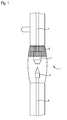
- FIG. 1 shows a section of an embodiment of a designed for DC operation (DC) with a power consumption of 450 W rare gas short arc discharge lamp in a view.
- the lamp has a discharge vessel 1 made of glass in which an anode 2 and a cathode 3 are arranged at a distance from one another are.
- the two electrodes 2, 3 are held in the discharge vessel 1 via respective electrode rods 4, 6.
- the electrode rods are in turn mounted in the respective end regions of the lamp or guided gas-tight to the outside to be able to be connected to external power supply lines (not shown).
- the discharge vessel 1 is filled with pure xenon gas at a cold filling pressure of 10 bar. This corresponds to the cold filling pressure of a conventional 450 W xenon short arc lamp.
- the coating 8 consists alternately of silicon oxide (SiO 2 ) and of niobium oxide (Nb 2 O 5 ) layers. These layers have significantly different refractive indices.
- an arc is initially ignited via a comparatively high ignition voltage between the two electrodes 2, 3, which arc extends through the xenon gas.
- the burning voltage that occurs between the electrodes after ignition is significantly lower than the ignition voltage.
- infrared heat radiation is generated, which increases the gas pressure in the entire discharge vessel 1.
- the heat radiation is incident in part on the coating 8 and is largely reflected by this back into the discharge vessel 1.
- the coating 8 is largely transparent to visible light.
- the reflection of the heat radiation the interior of the discharge vessel 1 is further heated, whereby the operating pressure is further increased. This leads to a narrowing (concentration) of the arc and specifically the point of highest luminance directly in front of the cathode tip (hot spot) which in consequence increases the luminance of the arc and the hot spot luminance in an advantageous manner.
- FIG. 2 shows a reflection diagram of the rare gas short arc discharge lamp.
- the percentages of the radiation reflected back into the discharge vessel 1 are applied over different wavelengths of the radiation emitted by the interior of the noble gas short arc discharge lamp.
- the visible light range of approx. 400 to 700 nm is plotted in the diagram on the left.
- a comparatively thick curve 10 represents the nominal spectrum of the coating 8 (cf. Fig. 1 ), while the three different thinner curves 12a, 12b, 12c show the proportion of the reflected radiation at three different exemplary measuring points of the noble gas short arc discharge lamp coated according to the invention.
- the diagram shows a low reflection in the visible light range through the coating 8, while in the infrared range (up to 2100 nm) the majority of the thermal radiation is reflected by the coating 8 back into the discharge vessel 1.
- the infrared-reflecting (IR) coating 8 produces an increased operating pressure in the discharge vessel 1, which increases by about 10% which results from comparable noble gas short arc discharge lamps (according to the prior art) increased luminance.
- the cold filling pressure of the discharge vessel is reduced by approximately 10% to approximately 9 bar.
- the necessary ignition voltage (cold ignition and hot re-ignition) of the discharge lamp is lowered by about 15%. This reduces the device complexity (ignitors, wiring).
- the gas pressure increases to the operating pressure originally provided for this type of lamp. As a result, despite the reduced cold filling pressure, the luminance achieved in the conventional counterpart without IR reflection coating is achieved.
- FIG. 3 shows a section of another embodiment. It is also a 450 W xenon short-arc discharge lamp 1.
- the IR reflection coating is not limited here to the area of the lamp vessel around the anode 2.
- the IR reflection coating 81 extends substantially in the region of the tip of the anode 2 along the anode rod 4.
- the lamp in Fig. 3 also on the cathode side on the outside of the lamp vessel to an IR reflective coating 82, which extends substantially along the cathode rod 6. Due to the expansion of the IR reflection coating of the lamp vessel on the region of the electrode rods 4, 6 is achieved that IR radiation on the electrode rods 4, 6 is reflected back and these are additionally heated.
Landscapes
- Vessels And Coating Films For Discharge Lamps (AREA)
- Discharge Lamp (AREA)
Applications Claiming Priority (1)
| Application Number | Priority Date | Filing Date | Title |
|---|---|---|---|
| DE102010028472A DE102010028472A1 (de) | 2010-05-03 | 2010-05-03 | Edelgas - Kurzbogen - Entladungslampe |
Publications (1)
| Publication Number | Publication Date |
|---|---|
| EP2390902A1 true EP2390902A1 (fr) | 2011-11-30 |
Family
ID=44486832
Family Applications (1)
| Application Number | Title | Priority Date | Filing Date |
|---|---|---|---|
| EP11160429A Withdrawn EP2390902A1 (fr) | 2010-05-03 | 2011-03-30 | Lampe à décharge à gaz noble à arc court |
Country Status (4)
| Country | Link |
|---|---|
| US (1) | US20110304267A1 (fr) |
| EP (1) | EP2390902A1 (fr) |
| CN (1) | CN102237253A (fr) |
| DE (1) | DE102010028472A1 (fr) |
Citations (4)
| Publication number | Priority date | Publication date | Assignee | Title |
|---|---|---|---|---|
| US3988626A (en) * | 1975-05-12 | 1976-10-26 | Eprad Incorporated | Magnetically stabilized xenon arc lamp |
| EP1217644A1 (fr) * | 2000-12-20 | 2002-06-26 | Patent-Treuhand-Gesellschaft für elektrische Glühlampen mbH | Lampe à décharge à haute pression et à arc court utilisée pour la projection d'images codées sous forme numérique |
| US20040057250A1 (en) * | 2002-09-23 | 2004-03-25 | Perkinelmer Optoelectronics N.C., Inc. | Xenon short-arc lamp with fiberoptic filters |
| WO2006027724A1 (fr) * | 2004-09-06 | 2006-03-16 | Koninklijke Philips Electronics N.V. | Lampe electrique et film d'interference |
Family Cites Families (11)
| Publication number | Priority date | Publication date | Assignee | Title |
|---|---|---|---|---|
| US4701664A (en) * | 1986-01-09 | 1987-10-20 | Becton, Dickinson And Company | Mercury arc lamp suitable for inclusion in a flow cytometry apparatus |
| DE8601283U1 (de) * | 1986-01-20 | 1986-08-28 | Patent-Treuhand-Gesellschaft für elektrische Glühlampen mbH, 8000 München | Kraftfahrzeugentladungslampe |
| US4998038A (en) * | 1988-12-05 | 1991-03-05 | Kabushiki Kaisha Toshiba | Pitted light diffusive coating, a method of forming the coating and a lamp having the coating |
| US5466988A (en) * | 1992-05-11 | 1995-11-14 | Matsushita Electric Industrial Co., Ltd. | High pressure discharge lamp having improved convection regulating means |
| JP3261961B2 (ja) * | 1995-12-20 | 2002-03-04 | ウシオ電機株式会社 | 放電ランプ |
| US6049169A (en) * | 1998-04-08 | 2000-04-11 | Philips Electronics North America Corp. | Electric lamp having optical interference filter of alternating layers of SiO2 and Nb2 O5 --Ta2 O5 |
| JP3603723B2 (ja) * | 1999-03-26 | 2004-12-22 | 松下電工株式会社 | メタルハライドランプ及び放電灯点灯装置 |
| KR20010110712A (ko) * | 2000-02-03 | 2001-12-13 | 롤페스 요하네스 게라투스 알베르투스 | 전기 램프 및 간섭막 |
| US7687979B2 (en) * | 2002-11-27 | 2010-03-30 | Koninklijke Philips Electronics N.V. | Electric lamp/reflector unit employing a ceramic insert |
| EP1616206A2 (fr) * | 2003-03-24 | 2006-01-18 | Philips Intellectual Property & Standards GmbH | Lampe |
| DE102009016057A1 (de) * | 2009-04-02 | 2010-10-07 | Osram Gesellschaft mit beschränkter Haftung | Elektrische Lampe mit Außenkolben |
-
2010
- 2010-05-03 DE DE102010028472A patent/DE102010028472A1/de not_active Withdrawn
-
2011
- 2011-03-30 EP EP11160429A patent/EP2390902A1/fr not_active Withdrawn
- 2011-05-03 CN CN2011101163178A patent/CN102237253A/zh active Pending
- 2011-05-03 US US13/100,040 patent/US20110304267A1/en not_active Abandoned
Patent Citations (5)
| Publication number | Priority date | Publication date | Assignee | Title |
|---|---|---|---|---|
| US3988626A (en) * | 1975-05-12 | 1976-10-26 | Eprad Incorporated | Magnetically stabilized xenon arc lamp |
| EP1217644A1 (fr) * | 2000-12-20 | 2002-06-26 | Patent-Treuhand-Gesellschaft für elektrische Glühlampen mbH | Lampe à décharge à haute pression et à arc court utilisée pour la projection d'images codées sous forme numérique |
| EP1217644B1 (fr) | 2000-12-20 | 2009-01-07 | Patent-Treuhand-Gesellschaft für elektrische Glühlampen mbH | Lampe à décharge à haute pression et à arc court utilisée pour la projection d'images codées sous forme numérique |
| US20040057250A1 (en) * | 2002-09-23 | 2004-03-25 | Perkinelmer Optoelectronics N.C., Inc. | Xenon short-arc lamp with fiberoptic filters |
| WO2006027724A1 (fr) * | 2004-09-06 | 2006-03-16 | Koninklijke Philips Electronics N.V. | Lampe electrique et film d'interference |
Non-Patent Citations (1)
| Title |
|---|
| MSSCIENTIFIC CHROMATOGRAPHIE-HANDEL GMBH: "UXR Ceramic Xenon Short-Arc Lamps from Ushio", 22 March 2009 (2009-03-22), XP002660402, Retrieved from the Internet <URL:http://web.archive.org/web/20090322041816/http://www.msscientific.de/ushio_uxr_xenon_short_arc_lamps.htm> [retrieved on 20110928] * |
Also Published As
| Publication number | Publication date |
|---|---|
| CN102237253A (zh) | 2011-11-09 |
| US20110304267A1 (en) | 2011-12-15 |
| DE102010028472A1 (de) | 2011-11-03 |
Similar Documents
| Publication | Publication Date | Title |
|---|---|---|
| EP0706201A2 (fr) | Lampe à arc court à vapeur de mercure | |
| DE102008013607B3 (de) | Quecksilberfreie Metallhalogenid-Hochdruckentladungslampe | |
| DE69514710T2 (de) | Metallhalogenidlampe | |
| DE2624897A1 (de) | Aluminiumoxyd-ueberzuege fuer quecksilberdampf-lampen | |
| DE3038993C2 (de) | Metalldampfentladungslampe | |
| EP0374678A2 (fr) | Lampe à décharge à haute pression de puissance électrique basse et méthode pour la faire fonctionner | |
| DE69703079T2 (de) | Hochdruck Quecksilber-Ultravioletlampe | |
| DE10039383A1 (de) | Blitzlampe und Blitzlampenaufbau | |
| EP0736222A1 (fr) | Lampe halogene a incandescence | |
| DE2619674C2 (de) | Halogen-Metalldampfentladungslampe | |
| DE69911539T2 (de) | Elektrische Lampe mit Interferenzfilter | |
| EP2499657B1 (fr) | Lampe à décharge haute pression sans mercure et à teneur réduite en halogénures de zinc | |
| EP1206794A1 (fr) | Source lumineuse et procede de fabrication de ladite source | |
| EP2147456B1 (fr) | Lampe à décharge haute pression et phare de véhicule automobile avec lampe à décharge haute pression | |
| EP0981831A1 (fr) | Lampe a decharge avec electrodes inhibees dielectriquement | |
| DE10204691C1 (de) | Quecksilberfreie Hochdruckgasentladungslampe und Beleuchtungseinheit mit einer solchen Hochdruckgasentladungslampe | |
| DE1489527B2 (de) | Quecksilberdampfhochdrucklampe | |
| DE102010028472A1 (de) | Edelgas - Kurzbogen - Entladungslampe | |
| DE69802256T2 (de) | Quecksilberlampe vom Kurzbogentyp | |
| DE2711733A1 (de) | Natriumdampf-hochdruckentladungslampe | |
| DE2941114C2 (de) | Hochdruck-Natriumdampf-Entladungslampe | |
| EP3031071B1 (fr) | Lampe à décharge à haute pression pour phare de véhicule | |
| DE1934299C3 (de) | Niederdruck-Quecksilberdampf-Entladungslampe | |
| DE1489527C3 (de) | Quecksilberdampfhochdrucklampe | |
| EP3072146B1 (fr) | Lampe à décharge à haute pression pour phare de véhicule automobile |
Legal Events
| Date | Code | Title | Description |
|---|---|---|---|
| AK | Designated contracting states |
Kind code of ref document: A1 Designated state(s): AL AT BE BG CH CY CZ DE DK EE ES FI FR GB GR HR HU IE IS IT LI LT LU LV MC MK MT NL NO PL PT RO RS SE SI SK SM TR |
|
| AX | Request for extension of the european patent |
Extension state: BA ME |
|
| PUAI | Public reference made under article 153(3) epc to a published international application that has entered the european phase |
Free format text: ORIGINAL CODE: 0009012 |
|
| STAA | Information on the status of an ep patent application or granted ep patent |
Free format text: STATUS: THE APPLICATION IS DEEMED TO BE WITHDRAWN |
|
| 18D | Application deemed to be withdrawn |
Effective date: 20120531 |