EP2390902A1 - Noble gas short arc discharge lamp - Google Patents
Noble gas short arc discharge lamp Download PDFInfo
- Publication number
- EP2390902A1 EP2390902A1 EP11160429A EP11160429A EP2390902A1 EP 2390902 A1 EP2390902 A1 EP 2390902A1 EP 11160429 A EP11160429 A EP 11160429A EP 11160429 A EP11160429 A EP 11160429A EP 2390902 A1 EP2390902 A1 EP 2390902A1
- Authority
- EP
- European Patent Office
- Prior art keywords
- discharge lamp
- arc discharge
- coating
- noble gas
- discharge vessel
- Prior art date
- Legal status (The legal status is an assumption and is not a legal conclusion. Google has not performed a legal analysis and makes no representation as to the accuracy of the status listed.)
- Withdrawn
Links
Images


Classifications
-
- H—ELECTRICITY
- H01—ELECTRIC ELEMENTS
- H01J—ELECTRIC DISCHARGE TUBES OR DISCHARGE LAMPS
- H01J61/00—Gas-discharge or vapour-discharge lamps
- H01J61/02—Details
- H01J61/30—Vessels; Containers
- H01J61/35—Vessels; Containers provided with coatings on the walls thereof; Selection of materials for the coatings
-
- H—ELECTRICITY
- H01—ELECTRIC ELEMENTS
- H01J—ELECTRIC DISCHARGE TUBES OR DISCHARGE LAMPS
- H01J61/00—Gas-discharge or vapour-discharge lamps
- H01J61/84—Lamps with discharge constricted by high pressure
- H01J61/86—Lamps with discharge constricted by high pressure with discharge additionally constricted by close spacing of electrodes, e.g. for optical projection
Definitions
- the invention is based on noble gas short arc discharge lamps according to the preamble of patent claim 1.
- noble gas short-arc discharge lamp here refers to short-arc discharge lamps with a discharge vessel made of quartz glass, which is filled exclusively with a noble gas or noble gas mixture. Such lamps are usually operated with direct current or pulsed direct current. These lamps are suitable for a variety of applications, in particular for the cinema projection, effect and searchlights, as well as microscopy and endoscopy.
- the patent EP 1 217 644 B1 shows in the FIG. 1 a generic noble gas short arc discharge lamp with xenon filling for the cinema projection.
- the object of the present invention is to provide a noble gas short-arc discharge lamp whose cold-ignition behavior is improved while the luminance remains the same or whose luminance is increased with constant cold-ignition behavior. This object is achieved by a noble gas short-arc discharge lamp having the features of patent claim 1.
- the noble gas short-arc discharge lamp according to the invention has a discharge vessel and electrodes arranged therein, between which an arc forms during operation of the lamp.
- the discharge vessel has, at least in sections, a coating for at least partial reflection of the electromagnetic radiation emitted during operation by the lamp components in the discharge vessel and by the excited filling gas, in particular the infrared (IR) thermal radiation.
- IR radiation infrared
- the wall of the discharge vessel, the filling gas and the lamp components of the discharge vessel struck by the reversion are additionally heated during operation of the lamp.
- the IR radiation would largely be emitted through the discharge vessel into the environment.
- the starting point for the following considerations is a conventional reference lamp without IR reflection coating. If now an otherwise identical lamp provided with the inventive IR reflection coating, the filling pressure is higher in operation with the same power consumption than in the reference lamp, whereby the discharge arc contracts more. As a result, and by the shortening of the electrode spacing during operation, a higher luminance is achieved in comparison to the reference lamp.
- the resulting due to the above-described heating effect increase the operating pressure of the lamp can be used to lower the cold pressure of the lamp so that the regular operating pressure of the lamp adjusts that would have set even with normal filling without heat reflection coating but at the same power consumption. Due to the lower cold pressure, the advantage is achieved that the necessary ignition voltage (cold ignition and hot re-ignition) of the discharge lamp is lower than in the reference lamp. At the same time, however, due to the IR reflection coating, the filling pressure during operation and consequently the luminance is the same as in the reference lamp.
- the reflection coating comprises a layer system with a plurality of layers.
- one layer of the layer system is alternated between a low refractive index material and a high refractive index material layer.
- the layer of the low refractive index material may comprise a material consisting of an oxide or a nitride or an oxynitride of one of the metals Si, Zr, Al, Sn, ZN and mixtures thereof (for example SiO 2 , ZrO 2 , Al 2 O 3 ).
- a preferred material for the layer of low refractive index material is SiO 2 .
- the material of the high-refractive-index layer includes, for example, a material of an oxide or a nitride or an oxynitride of one of the metals Nb, Ti, Ta, Hf, and mixtures thereof (for example, Nb 2 O 5 , TiO 2 , HfO 2 ). , It has proven to be advantageous to use Nb 2 O 5 as a layer.
- the layer system has at least 30 and at most 80 layers.
- the anode heats up particularly strong due to their size and therefore emits a lot of heat, it is preferred according to a first embodiment, when an anode adjacent to the region of the discharge vessel is coated.
- the discharge vessel is largely or even completely coated.
- the entire discharge vessel can be heated in operation by the infrared-reflective effect of the coating.
- the layer system in this case is preferably to be designed so that it is sufficiently transparent to light.
- the discharge vessel is filled with pure xenon gas or a xenon-krypton gas mixture.
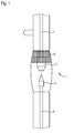
- FIG. 1 shows a section of an embodiment of a designed for DC operation (DC) with a power consumption of 450 W rare gas short arc discharge lamp in a view.
- the lamp has a discharge vessel 1 made of glass in which an anode 2 and a cathode 3 are arranged at a distance from one another are.
- the two electrodes 2, 3 are held in the discharge vessel 1 via respective electrode rods 4, 6.
- the electrode rods are in turn mounted in the respective end regions of the lamp or guided gas-tight to the outside to be able to be connected to external power supply lines (not shown).
- the discharge vessel 1 is filled with pure xenon gas at a cold filling pressure of 10 bar. This corresponds to the cold filling pressure of a conventional 450 W xenon short arc lamp.
- the coating 8 consists alternately of silicon oxide (SiO 2 ) and of niobium oxide (Nb 2 O 5 ) layers. These layers have significantly different refractive indices.
- an arc is initially ignited via a comparatively high ignition voltage between the two electrodes 2, 3, which arc extends through the xenon gas.
- the burning voltage that occurs between the electrodes after ignition is significantly lower than the ignition voltage.
- infrared heat radiation is generated, which increases the gas pressure in the entire discharge vessel 1.
- the heat radiation is incident in part on the coating 8 and is largely reflected by this back into the discharge vessel 1.
- the coating 8 is largely transparent to visible light.
- the reflection of the heat radiation the interior of the discharge vessel 1 is further heated, whereby the operating pressure is further increased. This leads to a narrowing (concentration) of the arc and specifically the point of highest luminance directly in front of the cathode tip (hot spot) which in consequence increases the luminance of the arc and the hot spot luminance in an advantageous manner.
- FIG. 2 shows a reflection diagram of the rare gas short arc discharge lamp.
- the percentages of the radiation reflected back into the discharge vessel 1 are applied over different wavelengths of the radiation emitted by the interior of the noble gas short arc discharge lamp.
- the visible light range of approx. 400 to 700 nm is plotted in the diagram on the left.
- a comparatively thick curve 10 represents the nominal spectrum of the coating 8 (cf. Fig. 1 ), while the three different thinner curves 12a, 12b, 12c show the proportion of the reflected radiation at three different exemplary measuring points of the noble gas short arc discharge lamp coated according to the invention.
- the diagram shows a low reflection in the visible light range through the coating 8, while in the infrared range (up to 2100 nm) the majority of the thermal radiation is reflected by the coating 8 back into the discharge vessel 1.
- the infrared-reflecting (IR) coating 8 produces an increased operating pressure in the discharge vessel 1, which increases by about 10% which results from comparable noble gas short arc discharge lamps (according to the prior art) increased luminance.
- the cold filling pressure of the discharge vessel is reduced by approximately 10% to approximately 9 bar.
- the necessary ignition voltage (cold ignition and hot re-ignition) of the discharge lamp is lowered by about 15%. This reduces the device complexity (ignitors, wiring).
- the gas pressure increases to the operating pressure originally provided for this type of lamp. As a result, despite the reduced cold filling pressure, the luminance achieved in the conventional counterpart without IR reflection coating is achieved.
- FIG. 3 shows a section of another embodiment. It is also a 450 W xenon short-arc discharge lamp 1.
- the IR reflection coating is not limited here to the area of the lamp vessel around the anode 2.
- the IR reflection coating 81 extends substantially in the region of the tip of the anode 2 along the anode rod 4.
- the lamp in Fig. 3 also on the cathode side on the outside of the lamp vessel to an IR reflective coating 82, which extends substantially along the cathode rod 6. Due to the expansion of the IR reflection coating of the lamp vessel on the region of the electrode rods 4, 6 is achieved that IR radiation on the electrode rods 4, 6 is reflected back and these are additionally heated.
Abstract
Description
Die Erfindung geht aus von Edelgas-Kurzbogen-Entladungslampen gemäß dem Oberbegriff des Patentanspruchs 1.The invention is based on noble gas short arc discharge lamps according to the preamble of patent claim 1.
Der Begriff Edelgas-Kurzbogen-Entladungslampe bezeichnet hier Kurzbogen-Entladungslampen mit einem Entladungsgefäß aus Quarzglas, das ausschließlich mit einem Edelgas oder Edelgasgemisch gefüllt ist. Derartige Lampen werden üblicherweise mit Gleichstrom oder gepulstem Gleichstrom betrieben. Diese Lampen eignen sich für vielfältige Einsatzgebiete, insbesondere auch für die Kinoprojektion, Effekt- und Suchscheinwerfer sowie Mikroskopie und Endoskopie.The term noble gas short-arc discharge lamp here refers to short-arc discharge lamps with a discharge vessel made of quartz glass, which is filled exclusively with a noble gas or noble gas mixture. Such lamps are usually operated with direct current or pulsed direct current. These lamps are suitable for a variety of applications, in particular for the cinema projection, effect and searchlights, as well as microscopy and endoscopy.
Als Maßnahme zu Erhöhung der Leuchtdichte einer Edelgas-Kurzbogen-Entladungslampe (AC, DC, Pulsbetrieb) ist es gemäß dem Stand der Technik bekannt, beispielsweise den Druck im Entladungsgefäß zu erhöhen. Dabei verändert sich jedoch das Zündverhalten der Entladungslampe negativ, da die erforderliche Zündspannung (Kaltzündung und HeißWiederzündung) zunimmt.As a measure to increase the luminance of a rare gas short arc discharge lamp (AC, DC, pulsed operation), it is known in the prior art, for example, to increase the pressure in the discharge vessel. However, the ignition behavior of the discharge lamp changes negatively, since the required ignition voltage (cold ignition and hot re-ignition) increases.
Die Patentschrift
Die Aufgabe der vorliegenden Erfindung ist es, eine Edelgas-Kurzbogen-Entladungslampe zu schaffen, deren Kaltzündverhalten bei gleichbleibender Leuchtdichte verbessert ist oder deren Leuchtdichte bei gleichbleibendem Kaltzündverhalten erhöht ist. Diese Aufgabe wird gelöst durch eine Edelgas-Kurzbogen-Entladungslampe mit den Merkmalen des Patentanspruchs 1.The object of the present invention is to provide a noble gas short-arc discharge lamp whose cold-ignition behavior is improved while the luminance remains the same or whose luminance is increased with constant cold-ignition behavior. This object is achieved by a noble gas short-arc discharge lamp having the features of patent claim 1.
Besonders vorteilhafte Ausgestaltungen finden sich in den abhängigen Ansprüchen.Particularly advantageous embodiments can be found in the dependent claims.
Die erfindungsgemäße Edelgas-Kurzbogen-Entladungslampe hat ein Entladungsgefäß und darin angeordneten Elektroden, zwischen denen sich im Betrieb der Lampe ein Lichtbogen bildet. Erfindungsgemäß weist das Entladungsgefäß zumindest abschnittsweise eine Beschichtung zur mindestens teilweisen Reflexion der im Betrieb von den im Entladungsgefäß befindlichen Lampenkomponenten sowie vom angeregten Füllgas abgegebenen elektromagnetischen Strahlung, insbesondere der Infrarot(IR)-Wärmestrahlung auf. Durch die dadurch hervorgerufene IR-Strahlungs-Rückreflexion wird im Betrieb der Lampe die Wand des Entladungsgefäßes, das Füllgas sowie die von der Rückstrahlung getroffenen Lampenkomponenten des Entladungsgefäßes zusätzlich erwärmt. Dies führt zu einer Erhöhung des Betriebsdrucks des Füllgases sowie zu einer Verlängerung der Elektrodenstäbe aufgrund der stärkeren Wärmeausdehnung und folglich zu einer Verkürzung des Elektrodenabstands. Ohne die IR-Reflexionsbeschichtung hingegen würde die IR-Strahlung großenteils durch das Entladungsgefäß hindurch in die Umgebung abgestrahlt werden.The noble gas short-arc discharge lamp according to the invention has a discharge vessel and electrodes arranged therein, between which an arc forms during operation of the lamp. According to the invention, the discharge vessel has, at least in sections, a coating for at least partial reflection of the electromagnetic radiation emitted during operation by the lamp components in the discharge vessel and by the excited filling gas, in particular the infrared (IR) thermal radiation. As a result of the IR radiation back reflection caused thereby, the wall of the discharge vessel, the filling gas and the lamp components of the discharge vessel struck by the reversion are additionally heated during operation of the lamp. This leads to an increase in the operating pressure of the filling gas and to an extension of the electrode rods due to the greater thermal expansion and consequently to a shortening of the electrode spacing. By contrast, without the IR reflection coating, the IR radiation would largely be emitted through the discharge vessel into the environment.
Diese Zusammenhänge können vorteilhaft für die folgenden beiden Ziele genutzt werden. Ausgangspunkt der folgenden Überlegungen ist dabei eine herkömmliche Referenzlampe ohne IR-Reflexionsbeschichtung. Wird nun eine ansonsten baugleiche Lampe mit der erfindungsgemäßen IR-Reflexionsbeschichtung versehen, ist im Betrieb bei gleicher Leistungsaufnahme der Fülldruck höher als bei der Referenzlampe, wodurch sich der Entladungsbogen stärker kontrahiert. Dadurch und durch die Verkürzung des Elektrodenabstands im Betrieb wird im Vergleich zur Referenzlampe eine höhere Leuchtdichte erzielt.These relationships can be used to advantage for the following two goals. The starting point for the following considerations is a conventional reference lamp without IR reflection coating. If now an otherwise identical lamp provided with the inventive IR reflection coating, the filling pressure is higher in operation with the same power consumption than in the reference lamp, whereby the discharge arc contracts more. As a result, and by the shortening of the electrode spacing during operation, a higher luminance is achieved in comparison to the reference lamp.
Alternativ kann die sich aufgrund des vorstehend erläuterten Erwärmungseffektes ergebende Erhöhung des Betriebsdrucks der Lampe genutzt werden, um den Kaltfülldruck der Lampe so abzusenken, dass sich der reguläre Betriebsdruck der Lampe einstellt, der sich auch bei Normalbefüllung ohne Wärmereflexionsbeschichtung aber bei gleicher Leistungsaufnahme eingestellt hätte. Durch den geringeren Kaltfülldruck wird der Vorteil erzielt, dass die nötige Zündspannung (Kaltzündung und Heißwiederzündung) der Entladungslampe geringer ist als bei der Referenzlampe. Gleichzeitig ist aber aufgrund der IR-Reflexionsbeschichtung der Fülldruck im Betrieb und folglich die Leuchtdichte gleich wie bei der Referenzlampe.Alternatively, the resulting due to the above-described heating effect increase the operating pressure of the lamp can be used to lower the cold pressure of the lamp so that the regular operating pressure of the lamp adjusts that would have set even with normal filling without heat reflection coating but at the same power consumption. Due to the lower cold pressure, the advantage is achieved that the necessary ignition voltage (cold ignition and hot re-ignition) of the discharge lamp is lower than in the reference lamp. At the same time, however, due to the IR reflection coating, the filling pressure during operation and consequently the luminance is the same as in the reference lamp.
Besonders gute Reflexionseigenschaften im infraroten Spektralbereich und damit optimierte Wärmeisolation der erfindungsgemäßen Edelgas-Kurzbogen-Entladungslampe lässt sich erreichen, wenn die Reflexions-Beschichtung aus einem Schichtsystem mit einer Mehrzahl von Schichten aufweist.Particularly good reflection properties in the infrared spectral range and thus optimized thermal insulation of the noble gas short arc discharge lamp according to the invention can be achieved if the reflection coating comprises a layer system with a plurality of layers.
Vorzugsweise ist jeweils eine Schicht des Schichtsystems aus einem Material mit niedrigem Brechungsindex und eine Schicht aus einem Material mit hohem Brechungsindex abgewechselt.Preferably, one layer of the layer system is alternated between a low refractive index material and a high refractive index material layer.
Die Schicht aus dem Material mit niedrigem Brechungsindex kann ein Material umfassen, das aus einem Oxid oder einem Nitrid oder aus einem Oxinitrid aus einem der Metalle Si, Zr, Al, Sn, ZN sowie aus Mischungen derselben besteht (beispielsweise SiO2, ZrO2, Al2O3). Ein bevorzugtes Material für die Schicht aus einem Material mit niedrigem Brechungsindex ist SiO2.The layer of the low refractive index material may comprise a material consisting of an oxide or a nitride or an oxynitride of one of the metals Si, Zr, Al, Sn, ZN and mixtures thereof (for example SiO 2 , ZrO 2 , Al 2 O 3 ). A preferred material for the layer of low refractive index material is SiO 2 .
Das Material der Schicht mit hohem Brechungsindex umfasst beispielsweise ein Material aus einem Oxid oder aus einem Nitrid oder aus einem Oxinitrid aus einem der Metalle Nb, Ti, Ta, Hf, sowie Mischungen derselben (beispielsweise Nb2O5, TiO2, HfO2). Es hat sich als vorteilhaft erwiesen, Nb2O5 als Schicht zu verwenden.The material of the high-refractive-index layer includes, for example, a material of an oxide or a nitride or an oxynitride of one of the metals Nb, Ti, Ta, Hf, and mixtures thereof (for example, Nb 2 O 5 , TiO 2 , HfO 2 ). , It has proven to be advantageous to use Nb 2 O 5 as a layer.
Das Schichtsystem hat mindestens 30 und höchstens 80 Schichten.The layer system has at least 30 and at most 80 layers.
Da im DC-Betrieb der erfindungsgemäßen Edelgas-Kurzbogen-Entladungslampe die Anode aufgrund ihrer Größe sich besonders stark erwärmt und demzufolge besonders viel Wärme abstrahlt, wird es gemäß einem ersten Ausführungsbeispiel bevorzugt, wenn ein zur Anode benachbarter Bereich des Entladungsgefäßes beschichtet ist.Since in DC operation of the noble gas short-arc discharge lamp according to the invention, the anode heats up particularly strong due to their size and therefore emits a lot of heat, it is preferred according to a first embodiment, when an anode adjacent to the region of the discharge vessel is coated.
Um möglichst viel der im Inneren der Edelgas-Kurzbogen-Entladungslampe produzierten Wärme zur Druckerhöhung zu nutzten, wird es gemäß einem anderen Ausführungsbeispiel bevorzugt, wenn das Entladungsgefäß weitgehend oder sogar komplett beschichtet ist. Damit lässt sich im Betrieb durch die infrarot-reflektierende Wirkung der Beschichtung das gesamte Entladungsgefäß erwärmen. Allerdings ist das Schichtsystem in diesem Fall vorzugsweise so auszulegen, dass es für Licht ausreichend transparent ist.To as much as possible of the heat produced in the interior of the noble gas short-arc discharge lamp for pressure increase used, it is preferred according to another embodiment, when the discharge vessel is largely or even completely coated. Thus, the entire discharge vessel can be heated in operation by the infrared-reflective effect of the coating. However, the layer system in this case is preferably to be designed so that it is sufficiently transparent to light.
Bei einem Ausführungsbeispiel ist das Entladungsgefäß mit reinem Xenon-Gas oder einem Xenon-Krypton Gasgemisch befüllt.In one embodiment, the discharge vessel is filled with pure xenon gas or a xenon-krypton gas mixture.
Im Folgenden soll die Erfindung anhand von Ausführungsbeispielen näher erläutert werden. Die Figuren zeigen:
-
Fig. 1 ein Ausführungsbeispiel einer Xenon-Kurzbogen-Entladungslampe(XBO) mit erfindungsgemäßer Beschichtung; -
Fig. 2 ein Reflexions-Diagramm; und -
Fig. 3 ein weiteres Ausführungsbeispiel einer Xenon-Kurzbogen-Entladungslampe.
-
Fig. 1 an embodiment of a xenon short arc discharge lamp (XBO) with inventive coating; -
Fig. 2 a reflection diagram; and -
Fig. 3 Another embodiment of a xenon short-arc discharge lamp.
Im Bereich der Anode 2 ist die Außenseite des Entladungsgefäßes 1 mit einer Beschichtung 8 versehen. Die Beschichtung 8 besteht dabei abwechselnd aus Siliziumoxid (SiO2) und aus Nioboxid (Nb2O5) Schichten. Diese Schichten haben deutlich voneinander abweichende Brechungsindizes.In the region of the
Zum Betreiben der erfindungsgemäßen Edelgas-Kurzbogen-Entladungslampe wird zunächst über eine vergleichsweise hohe Zündspannung zwischen den beiden Elektroden 2, 3 ein Lichtbogen gezündet, der sich durch das Xenon-Gas erstreckt. Die Brennspannung, die sich nach dem Zünden zwischen den Elektroden einstellt, ist deutlich geringer als die Zündspannung. Im Betrieb entsteht im Entladungsgefäß 1 und insbesondere durch die heiße Anode 2 infrarote Wärmestrahlung, wodurch sich im gesamten Entladungsgefäß 1 der Gasdruck erhöht. Die Wärmestrahlung trifft teilweise auf die Beschichtung 8 und wird von dieser weitgehend in das Entladungsgefäß 1 zurück reflektiert. Dabei ist die Beschichtung 8 für sichtbares Licht weitgehend durchlässig. Durch die Reflektion der Wärmestrahlung wird das Innere des Entladungsgefäßes 1 weiter aufgeheizt, wodurch der Betriebsdruck weiter erhöht wird. Dies führt zu einer Einengung (Konzentration) des Lichtbogens und speziell des Punktes höchster Leuchtdichte direkt vor der Kathodenspitze (Hot-Spot) was in Folge die Leuchtdichte des Lichtbogens sowie die Hot-Spot-Leuchtdichte in vorteilhafter Weise erhöht.To operate the noble gas short-arc discharge lamp according to the invention, an arc is initially ignited via a comparatively high ignition voltage between the two
Eine vergleichsweise dick gezeichnete Kurve 10 stellt das Soll-Spektrum der Beschichtung 8 (vgl.
Im Bereich der Wellenlänge von ca. 1050 bis ca. 1200 nm liegen auf Grund eines Messbereichssprungs des Spektrometers keine Messwerte vor.In the range of the wavelength from about 1050 to about 1200 nm, no measured values are available due to a change in the measuring range of the spectrometer.
Das Diagramm zeigt im Bereich des sichtbaren Lichtes eine geringe Reflektion durch die Beschichtung 8, während im Infrarotbereich (bis 2100 nm) der Großteil der Wärmestrahlung durch die Beschichtung 8 in das Entladungsgefäß 1 zurück reflektiert wird.The diagram shows a low reflection in the visible light range through the
Durch die erfindungsgemäße infrarot-reflektierende(IR) Beschichtung 8 entsteht im Betrieb ein erhöhter Betriebsdruck im Entladungsgefäß 1, der zu einer um ca. 10% über dem von vergleichbaren Edelgas-Kurzbogen-Entladungslampen (gemäß dem Stand der Technik) erhöhten Leuchtdichte führt.During operation, the infrared-reflecting (IR)
In einer alternativen Variante des oben erläuterten Ausführungsbeispiels einer 450 W Xenon-Kurzbogen-Entladungslampe ist der Kaltfülldruck des Entladungsgefäßes um ca. 10% auf ca. 9 bar verringert. Dadurch ist die nötige Zündspannung (Kaltzündung und Heißwiederzündung) der Entladungslampe um ca. 15 % abgesenkt. Dadurch verringert sich der vorrichtungstechnische Aufwand (Zündgeräte, Leitungsführung). Im Betrieb erhöht sich aufgrund er IR-Reflexionsbeschichtung der Gasdruck auf die ursprünglich für diesen Lampentyp vorgesehenen Betriebsdruck. Dadurch wird auch - trotz vermindertem Kaltfülldruck - die beim konventionellen Pendant ohne IR-Reflexionsbeschichtung erzielte Leuchtdichte erreicht.In an alternative variant of the above-described embodiment of a 450 W xenon short-arc discharge lamp, the cold filling pressure of the discharge vessel is reduced by approximately 10% to approximately 9 bar. As a result, the necessary ignition voltage (cold ignition and hot re-ignition) of the discharge lamp is lowered by about 15%. This reduces the device complexity (ignitors, wiring). In operation, due to the IR reflection coating, the gas pressure increases to the operating pressure originally provided for this type of lamp. As a result, despite the reduced cold filling pressure, the luminance achieved in the conventional counterpart without IR reflection coating is achieved.
Claims (9)
Applications Claiming Priority (1)
| Application Number | Priority Date | Filing Date | Title |
|---|---|---|---|
| DE102010028472A DE102010028472A1 (en) | 2010-05-03 | 2010-05-03 | Noble gas - short arc - discharge lamp |
Publications (1)
| Publication Number | Publication Date |
|---|---|
| EP2390902A1 true EP2390902A1 (en) | 2011-11-30 |
Family
ID=44486832
Family Applications (1)
| Application Number | Title | Priority Date | Filing Date |
|---|---|---|---|
| EP11160429A Withdrawn EP2390902A1 (en) | 2010-05-03 | 2011-03-30 | Noble gas short arc discharge lamp |
Country Status (4)
| Country | Link |
|---|---|
| US (1) | US20110304267A1 (en) |
| EP (1) | EP2390902A1 (en) |
| CN (1) | CN102237253A (en) |
| DE (1) | DE102010028472A1 (en) |
Citations (4)
| Publication number | Priority date | Publication date | Assignee | Title |
|---|---|---|---|---|
| US3988626A (en) * | 1975-05-12 | 1976-10-26 | Eprad Incorporated | Magnetically stabilized xenon arc lamp |
| EP1217644A1 (en) * | 2000-12-20 | 2002-06-26 | Patent-Treuhand-Gesellschaft für elektrische Glühlampen mbH | Short arc high pressure discharge lamp for use in digital projection techniques |
| US20040057250A1 (en) * | 2002-09-23 | 2004-03-25 | Perkinelmer Optoelectronics N.C., Inc. | Xenon short-arc lamp with fiberoptic filters |
| WO2006027724A1 (en) * | 2004-09-06 | 2006-03-16 | Koninklijke Philips Electronics N.V. | Electric lamp and interference film |
Family Cites Families (11)
| Publication number | Priority date | Publication date | Assignee | Title |
|---|---|---|---|---|
| US4701664A (en) * | 1986-01-09 | 1987-10-20 | Becton, Dickinson And Company | Mercury arc lamp suitable for inclusion in a flow cytometry apparatus |
| DE8601283U1 (en) * | 1986-01-20 | 1986-08-28 | Patent-Treuhand-Gesellschaft für elektrische Glühlampen mbH, 8000 München | Motor vehicle discharge lamp |
| US4998038A (en) * | 1988-12-05 | 1991-03-05 | Kabushiki Kaisha Toshiba | Pitted light diffusive coating, a method of forming the coating and a lamp having the coating |
| US5466988A (en) * | 1992-05-11 | 1995-11-14 | Matsushita Electric Industrial Co., Ltd. | High pressure discharge lamp having improved convection regulating means |
| JP3261961B2 (en) * | 1995-12-20 | 2002-03-04 | ウシオ電機株式会社 | Discharge lamp |
| US6049169A (en) * | 1998-04-08 | 2000-04-11 | Philips Electronics North America Corp. | Electric lamp having optical interference filter of alternating layers of SiO2 and Nb2 O5 --Ta2 O5 |
| JP3603723B2 (en) * | 1999-03-26 | 2004-12-22 | 松下電工株式会社 | Metal halide lamp and discharge lamp lighting device |
| EP1190268A2 (en) * | 2000-02-03 | 2002-03-27 | Koninklijke Philips Electronics N.V. | Electric lamp and interference film |
| WO2004049392A1 (en) * | 2002-11-27 | 2004-06-10 | Koninklijke Philips Electronics N.V. | Electric lamp/reflector unit |
| WO2004086105A2 (en) * | 2003-03-24 | 2004-10-07 | Philips Intellectual Property & Standards Gmbh | Lamp |
| DE102009016057A1 (en) * | 2009-04-02 | 2010-10-07 | Osram Gesellschaft mit beschränkter Haftung | Electric lamp with outer bulb |
-
2010
- 2010-05-03 DE DE102010028472A patent/DE102010028472A1/en not_active Withdrawn
-
2011
- 2011-03-30 EP EP11160429A patent/EP2390902A1/en not_active Withdrawn
- 2011-05-03 CN CN2011101163178A patent/CN102237253A/en active Pending
- 2011-05-03 US US13/100,040 patent/US20110304267A1/en not_active Abandoned
Patent Citations (5)
| Publication number | Priority date | Publication date | Assignee | Title |
|---|---|---|---|---|
| US3988626A (en) * | 1975-05-12 | 1976-10-26 | Eprad Incorporated | Magnetically stabilized xenon arc lamp |
| EP1217644A1 (en) * | 2000-12-20 | 2002-06-26 | Patent-Treuhand-Gesellschaft für elektrische Glühlampen mbH | Short arc high pressure discharge lamp for use in digital projection techniques |
| EP1217644B1 (en) | 2000-12-20 | 2009-01-07 | Patent-Treuhand-Gesellschaft für elektrische Glühlampen mbH | Short arc high pressure discharge lamp for use in digital projection techniques |
| US20040057250A1 (en) * | 2002-09-23 | 2004-03-25 | Perkinelmer Optoelectronics N.C., Inc. | Xenon short-arc lamp with fiberoptic filters |
| WO2006027724A1 (en) * | 2004-09-06 | 2006-03-16 | Koninklijke Philips Electronics N.V. | Electric lamp and interference film |
Non-Patent Citations (1)
| Title |
|---|
| MSSCIENTIFIC CHROMATOGRAPHIE-HANDEL GMBH: "UXR Ceramic Xenon Short-Arc Lamps from Ushio", 22 March 2009 (2009-03-22), XP002660402, Retrieved from the Internet <URL:http://web.archive.org/web/20090322041816/http://www.msscientific.de/ushio_uxr_xenon_short_arc_lamps.htm> [retrieved on 20110928] * |
Also Published As
| Publication number | Publication date |
|---|---|
| DE102010028472A1 (en) | 2011-11-03 |
| US20110304267A1 (en) | 2011-12-15 |
| CN102237253A (en) | 2011-11-09 |
Similar Documents
| Publication | Publication Date | Title |
|---|---|---|
| DE112013007825B4 (en) | PLASMA CELL OF A PLASMA LIGHT SOURCE MAINTAINED BY A LASER WITH AN ARRANGEMENT FOR ROTATION OF THE PLASMA PISTON AND A LIQUID FOR FILTERING VUV RADIATION | |
| EP0706201A2 (en) | Mercury vapour lamp with short arc | |
| EP2128888B1 (en) | Mercury-free metal halide high pressure discharge lamp | |
| DE2624897A1 (en) | ALUMINUM OXYDE COVERS FOR MERCURY VAPOR LAMPS | |
| EP0374678A2 (en) | High-pressure discharge lamp requiring low electric power, and method for operating it | |
| DE10039383A1 (en) | Flash lamp and flash lamp construction | |
| DE3038993C2 (en) | Metal vapor discharge lamp | |
| DE2619674C2 (en) | Metal halide discharge lamp | |
| WO1995017764A1 (en) | Halogen incandescent lamp | |
| EP1206794A1 (en) | Light source and method for producing a light source | |
| WO1999048134A1 (en) | Discharge lamp with dielectrically impeded electrodes | |
| DE10204691C1 (en) | Mercury-free, high-intensity, high pressure gas discharge lamp for vehicle headlights, has infra-red reflecting coating on lower wall to promote vaporization | |
| DE102009052999A1 (en) | High pressure discharge lamp | |
| DE1489527B2 (en) | HIGH PRESSURE MERCURY VAPOR LAMP | |
| EP2147456B1 (en) | High-pressure discharge lamp and vehicle headlight with high-pressure discharge lamp | |
| EP2390902A1 (en) | Noble gas short arc discharge lamp | |
| DE1764015A1 (en) | High-pressure discharge lamp with great output and excellent color rendering | |
| DE2711733A1 (en) | SODIUM VAPOR HIGH PRESSURE DISCHARGE LAMP | |
| EP2673796B1 (en) | High-pressure discharge lamp having an ignition aid | |
| DE604986C (en) | Discharge tubes with glow electrodes heated by the discharge and gas or steam filling | |
| DE2941114C2 (en) | High pressure sodium vapor discharge lamp | |
| EP3031071B1 (en) | High-pressure discharge lamp for vehicle headlights | |
| DD270406A1 (en) | Wall-stabilized metal vapor discharge lamp | |
| EP3072146B1 (en) | High-intensity discharge lamp for motor vehicle headlights | |
| DE1934299C3 (en) | Low pressure mercury vapor discharge lamp |
Legal Events
| Date | Code | Title | Description |
|---|---|---|---|
| AK | Designated contracting states |
Kind code of ref document: A1 Designated state(s): AL AT BE BG CH CY CZ DE DK EE ES FI FR GB GR HR HU IE IS IT LI LT LU LV MC MK MT NL NO PL PT RO RS SE SI SK SM TR |
|
| AX | Request for extension of the european patent |
Extension state: BA ME |
|
| PUAI | Public reference made under article 153(3) epc to a published international application that has entered the european phase |
Free format text: ORIGINAL CODE: 0009012 |
|
| STAA | Information on the status of an ep patent application or granted ep patent |
Free format text: STATUS: THE APPLICATION IS DEEMED TO BE WITHDRAWN |
|
| 18D | Application deemed to be withdrawn |
Effective date: 20120531 |