EP2390843B1 - Visualisierungsverarbeitungsverfahren und -vorrichtung - Google Patents
Visualisierungsverarbeitungsverfahren und -vorrichtung Download PDFInfo
- Publication number
- EP2390843B1 EP2390843B1 EP11163832A EP11163832A EP2390843B1 EP 2390843 B1 EP2390843 B1 EP 2390843B1 EP 11163832 A EP11163832 A EP 11163832A EP 11163832 A EP11163832 A EP 11163832A EP 2390843 B1 EP2390843 B1 EP 2390843B1
- Authority
- EP
- European Patent Office
- Prior art keywords
- data
- mask surface
- storage unit
- data storage
- visualization
- Prior art date
- Legal status (The legal status is an assumption and is not a legal conclusion. Google has not performed a legal analysis and makes no representation as to the accuracy of the status listed.)
- Not-in-force
Links
Images






Classifications
-
- G—PHYSICS
- G06—COMPUTING OR CALCULATING; COUNTING
- G06T—IMAGE DATA PROCESSING OR GENERATION, IN GENERAL
- G06T15/00—Three-dimensional [3D] image rendering
- G06T15/10—Geometric effects
- G06T15/40—Hidden part removal
-
- G—PHYSICS
- G06—COMPUTING OR CALCULATING; COUNTING
- G06T—IMAGE DATA PROCESSING OR GENERATION, IN GENERAL
- G06T15/00—Three-dimensional [3D] image rendering
- G06T15/50—Lighting effects
Definitions
- This technique relates to a visualization technique of data such as numerical calculation results.
- Enormous sized data that exceeds terabytes or petabytes is sometimes outputted from an application that is executed on a large-scale computer.
- This output data is data expressing a wide variety of phenomena such as physical or chemical phenomena, and in order to observe such phenomena, graphical illustration (or in other words, visualization) of that output data is required.
- graphical illustration or in other words, visualization
- FIG. 1 when vectors representing physical quantities that are obtained through numerical calculation (generally, includes simple calculation values that are not physical quantities) are arranged at plural points in 3D space without any design or plan, it is not possible to easily recognize what kind of phenomena or condition is portrayed.
- a calculation processing unit finds the Z-axis distance of that depth point from 3D data of an object, which is stored in a data storage unit, and the calculation processing unit uses a "blur function" to further calculate the degree of the blur of that object according to the Z-axis distance that was calculated, and provides the degree of the blur to a display processing unit together with the object data.
- the display processing unit displays the object on a display screen according to that object data and blur function.
- JP 2000-354257A also exists in which, in order to display a stereo image that is closer to an object in real space, the blur is generated in an image for areas other than the point of interest included in a display image, according to the distance with the object, which is an element that is the object of attention, or the like. More specifically, the position of the point of interest is acquired, and a blurred image is generated based on 3D information relating to the display image.
- the distance of the display element, which is arranged at the position corresponding to the position of the point of interest, from the viewpoint is calculated as a reference distance, and display elements whose difference from the reference distance exceeds a predetermined threshold value become a target of a generation processing of the blurred image.
- a special generation processing of the blurred image must be carried out for each of the display elements having a distance longer than the reference distance, and thus the processing load is high.
- JP 2005-100115A for displaying blurredpolygons in at least one of the front direction and rear direction of the point of interest in a virtual space. More specifically, based on 3D coordinates in the virtual space, the Z value of each polygon is calculated in the depth direction from the position of the viewpoint, and a first image is generated by carrying out the perspective transformation of only polygons having a small Z value onto a screen plane.
- the perspective transformation is a processing to conduct the coordinate transformation based on the screen transformation matrix M.
- the second image is generated by deteriorating the image quality of the first image and making the size of the second image equal to the size of the first image.
- a processing for making the first image semitransparent based on a transparency factor ⁇ , which is calculated based on the Z values of the respective polygons is carried out, and the processed first image is synthesized with the second image to generate the display image.
- a special processing is required in which, after generating a special first image, the second image corresponding to the first image is generated.
- a technique in which, in the process of determining the position of objects and generating 2D images of the objects, a 2D image having a simplified shape is generated for objects that are located far away from the position of the viewpoint, and generation of a 2D image itself is omitted for objects that are located even further away from the position of the viewpoint, and such objects are not displayed.
- JP 08-315173A provides a graphics apparatus for generating and outputting a 2D image of an object as seen from a designated position of the viewpoint in the direction of the designated view line, based on 3D structure data that expresses the structure of an object.
- This graphics apparatus includes a semitransparent plane positioning means for determining a position at arranging a semitransparent plane at the position of the view point, which corresponds to calculation for defocusing the objects located on the far side in the direction of the view line: and image defocusing means for performing a defocusing operation for a 2D image or part of the 2D image that corresponds to an object or part of the object that is located behind the position of the semitransparent plane that was arranged by the semitransparent plane positioning means, when viewed from the viewpoint in the direction of the view line.
- the semitransparent plane is a means for defocusing objects that are far from the viewpoint to some degrees and that originally can hardly be seen, and is not something to be used by a user to intentionally designate a desired range to be viewed.
- a mask processing method includes: generating data of a mask surface with respect to visualization data for respective calculation points, wherein the visualization data is arranged in a virtual three-dimensional space, each of the calculation points having a calculation value and represented as a position in the virtual three-dimensional space; identifying, from a numerical value data storage unit storing, as time-series data, positions of the respective calculation points and calculation values at the respective calculation points, a first point whose position is closest to a predetermined point on the mask surface; and for each unit time in the time-series data: reading out, from the numerical value data storage unit, a position of the identified first point; arranging the mask surface based on a direction of a user's sight line and the read position so as to make the mask surface perpendicular to the direction of the user's sight line and make the predetermined point on the mask surface coincide with the read position; and instructing to draw polygon data relating to the visualization data and polygon data relating to the mask surface in time series.
- a mask processing method include: generating data of a mask surface for visualization data for respective calculation points, wherein the visualization data is arranged in a virtual three-dimensional space, each of the calculation points having a calculation value and represented as a position in the virtual three-dimensional space; arranging the mask surface at a position away from a camera position by a predetermined distance in a direction of a sight line in the virtual three-dimensional space, according to data stored in a data storage unit storing data of the camera position and the direction of the sight line and data defining an arrangement position of the mask surface on the direction of the sight line; instructing to draw first polygon data relating to the visualization data and second polygon data relating to the mask surface without any discrimination of the first and second polygon data; accepting a change instruction of data defining the arrangement position of the mask surface from a user, and updating data relating to the change instruction in the data storage unit; and executing the arranging and the instructing in response to the accepting and updating.
- FIG. 2 schematically illustrates the scene of visualization data 100 having the depth length A in the direction of the sight line from the camera position as viewed by a user from the side.
- a mask surface 200 is located at a position away from the camera position (also called the viewpoint) by the distance "a" in order to set an area in front of the mask surface 200 as an area of interest. Accordingly, it becomes easy for the user to see only a portion of interest in the visualization data 100, which is located within the area of interest.
- the portion of the visualization data 100 within the distance "b" included in the depth length A is masked by the mask surface 200 so that there is no adverse effect on the display of the portion of interest in the visualization data 100.
- the mask surface 200 by setting the mask surface 200 at an appropriate position, it is possible to set a portion desired by the user as the portion of interest.
- the display depicted in FIG. 1 changes as illustrated in FIG. 3 .
- individual arrows that represent physical quantities become clearly visible (in FIG. 3 , a color image is converted to a grayscale image so the "white” color is difficult to see). That is, the display of the portion of interest in the visualization data 100 becomes easy to discern.
- the visualization data 100 may be generated as time-series data.
- the form and position of the visualization data 100 change according to time.
- simply placing the mask surface 200 at a position separated a distance "a" from the camera position does not absolutely mean that the portion of interest in the visualization data 100 will be displayed such that it is easy to discern.
- the portion of interest may move backward behind the mask surface 200. Therefore, when the visualization data 100 changes over time, as illustrated in FIG. 4 , the mask surface 200 is linked in the initial state with an element X (for example, particles or a bond between particles) that is located at the boundary between the portion of interest and the portion that is not of interest in the visualization data 100.
- element X for example, particles or a bond between particles
- the portion of interest in the visualization data 100 is always located in front of the mask surface 200 at time after the linking. Therefore, even when the visualization data 100 may change over time, the portion of interest continues to be displayed so that it is easily identified.
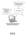
- a numerical simulation server 2 that performs simulation in fields such as biology, technology, environment and the like
- a file server 3 that manages a numerical data storage unit 4 that stores that numerical data (also called “numerical value data") resulting from the simulation that was performed by the numerical simulation server 2
- a visualization data display processing apparatus 5 that performs the main processing of this embodiment and has a display device are connected to a network 1 such as an LAN (Local Area Network).
- the visualization data display processing apparatus 5 acquires numerical data that is the object of visualization from among the numerical data stored in the numerical data storage unit 4, from the file server 3, and performs the processing described below.
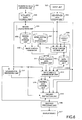
- FIG. 6 illustrates a functional block diagram of the visualization data display processing apparatus 5.
- the visualization data display processing apparatus 5 has: (A) a numerical data obtaining unit 501 that obtains numerical data that is the object of visualization and is stored in the numerical data storage unit 4 from the file server 3; (B) a numerical data storage unit 502 that stores the numerical data obtained by the numerical data obtaining unit 501; (C) an input unit 503 that accepts instructions fromauser; (D) an instruction data storage unit 504 that stores data concerning the instruction from the user, which was received by the input unit 503; (E) a visualization processing unit 512 that performs a known visualization processing from the numerical data stored in the numerical data storage unit 502; (F) a region calculation unit 505 that performs a processing using data that is stored in the numerical data storage unit 502; (G) a region data storage unit 506 that stores processing results of the region calculation unit 505; (H) an initial setting data storage unit 507 that stores initial setting data; (I) a known lookup table 508
- the visualization processing unit 512 cooperates together with the drawing instruction unit 515, in order to obtain synchronization, for example.
- the drawing instruction unit 515 and mask surface arrangement unit 513 cooperate with each other to carry out a processing described below.
- the drawing instruction unit 515 is able to reference the numerical data storage unit 502.
- FIG. 7 illustrates a table representing position data at calculation points in the virtual space, for which physical quantities (typically, this also includes simple calculated values) are calculated, wherein x coordinate values, y coordinate values and z coordinate values are registered for each calculation point ID, which is an identifier of the calculation point.
- physical quantities typically, this also includes simple calculated values
- the physical quantity is a value such as a scalar value, vector value or a tensor value.
- the visualization data is data such as data for displaying a contour surface of these values, data for displaying objects such as lines, arrows, ellipses and the like based on vectors or tensors, data for displaying an external shape that is understood from physical quantities (for example, an object after cutting, which is obtained by simulation of a machine tool or the like).
- the physical quantity is data for particles, a display with the particles is carried out.
- FIG. 8 represents data that defines elements formed by calculation points, and particularly represents data that defines line elements. More specifically, for each element ID of the line element, calculation point IDs of both edges are registered. In addition, elements are not limited to the line elements, and when an element is a quadrangle element, then as illustrated in FIG. 9 , calculation point IDs of four vertices are registered for each element ID. In addition to this, hexahedron elements or other elements may be defined.
- the coordinates of the center point are also registered for each element.
- the x coordinate, y coordinate and z coordinate of the center point are registered for each element ID.
- the calculated physical quantity for the calculation point is registered for each calculation point ID.
- such data sets are prepared for each unit time, for example.
- plural data sets are stored into the numerical data storage unit 502.
- FIG. 7 to FIG. 11 represent only one data set.
- Data as illustrated in FIG. 12 is stored in the initial setting data storage unit 507.
- the shape (for example, a circle) of the mask surface 200, color (for example, adaptive setting as described below (Adaptive), or a fixed color setting (for example, "white”)) , ⁇ value, distance from the camera position, initial camera position and initial direction of the sight line are set into the initial setting data storage unit 507.
- the numerical data obtaining unit 501 obtains the numerical data that is the object of the processing from the file server 3 and stores the obtained data into the numerical data storage unit 502.
- the visualization processing unit 512 carries out a known visualization data generation processing for the first numerical data stored in the numerical data storage unit 502 in response to an instruction from the drawing instruction unit 515 or from the outside such as a user, and stores polygon data for the first numerical data into the polygon data storage unit 514.
- data such as in FIG. 13A to 13C are generated.
- FIG. 13A illustrates an example in which, for each object, all of the generated polygon IDs are registered.
- FIG. 13B illustrates an example in which, for one polygon, the color, ⁇ value, and vertex IDs for that polygon are registered.
- FIG. 13C illustrates an example in which the x-coordinate value, y-coordinate value and z-coordinate value are registered for each vertex.
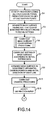
- the region calculation unit 505 identifies a region that includes all of the calculation points from the coordinate values of the calculation points that are included in the numerical data stored in the numerical data storage unit 502, and stores the data of the identified region into the region data storage unit 506 ( FIG. 14 : step S1).
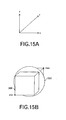
- a region 300 that covers all of the calculation points is identified as illustrated in FIG. 15B . More specifically, the minimum value of the x coordinate, the minimum value of the y-coordinate and the minimum value of the z-coordinate in the calculation points are identified, to set a point "min" as illustrated in FIG. 15B .
- the maximum value of the x coordinate, the maximum value of the y-coordinate and the maximum value of the z-coordinate in the calculation points are identified, to set a point "max" as illustrated in FIG. 15B .
- a rectangular solid having these min point and max point as the vertices at opposing corners is identified as the region described above.
- the mask surface generator 509 uses data of the region stored in the region data storage unit 506, and the initial setting data that is stored in the initial setting data storage unit 507 to generate a mask surface (more specifically, polygon data) having a size that covers the region identified at the step S1, and stores the data of the generated mask surface into the mask surface data storage unit 511 (step S3).
- a mask surface more specifically, polygon data
- the shape is a "circle”. Therefore, as schematically illustrated in FIG. 15B , the mask surface generator 509 generates a disk-type mask surface 200 that is perpendicular to the z-axis and has a diameter that sufficiently covers all of the surfaces of the region, for example.
- the mask surface may be such that it covers one of the surfaces of the region.
- the mask surface 200 is perpendicular to the direction of the sight line and it moves in connection with change of the direction of the sight line. Therefore, it is preferable that the mask surface 200 has a size such that it sufficiently covers all of the surfaces of the region.
- the generated polygon data has data structure as well as the polygon data of the visualization data 100 as illustrated in FIG. 13A to FIG. 13C .
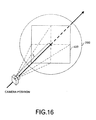
- the size of the mask surface is set such that a visible region 400 as seen from the camera position can be covered. Normally, the visible region 400 becomes larger the farther away it is from the camera position. Therefore, for example, the size of the visible region 400 at the max point is calculated using data such as the initial camera position, and the size of the mask surface 200 is determined such that it becomes larger than that size.
- the mask surface setting unit 510 carries out a processing to set the color of the mask surface (step S5).
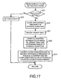
- This processing to set the color of the mask surface will be explained using FIG. 17 to FIG. 19 .
- the mask surface setting unit 510 checks the setting of the color in the initial setting data that is stored in the initial setting data storage unit 507, and determines whether a fixed color has been set (step S21). For example, when a fixed color such as "white" is set, the mask surface setting unit 510 sets that fixed color to the polygon data of the mask surface 200, which is stored in the polygon data storage unit 514 (step S23). The processing then returns to the calling-source processing.
- the color may be set such that the color changes from the center of the circle toward the circumference.
- data for texture mapping is stored into the polygon data storage unit 514.
- the mask surface setting unit 510 counts the frequency of appearance of physical quantities at the respective calculation points, which are included in the numerical data stored in the numerical data storage unit 502 (step S25). As illustrated at the top of FIG. 18 , when the frequency of appearance is plotted for each value of the physical quantity in a graph where the physical quantity is expressed along the horizontal axis and the frequency of appearance is expressed along the vertical axis, a distribution such as a curve "a" is obtained.
- the mask surface setting unit 510 reads out data from a lookup table 508 (step S27), and carries out the mapping between a color range that is defined in the lookup table 508 and an appearance range of the physical quantity (step S29) . From the graph at the top of FIG. 18 , it is possible to know the appearance range of the physical quantity, and here the colors on both ends of the color range that is defined by the lookup table 508 (blue (B) and red (R) in FIG. 18 ) are correlated with the lower limit value and upper limit value of the physical quantity, and colors within the color range (colors from blue to red in FIG. 18 ) are correlated with each value from the upper limit value to the lower limit value of the physical quantity.
- the mask surface setting unit 510 then identifies the color corresponding to the physical quantity having the highest frequency of appearance, and sets a complimentary color of the identified color as the color of the mask surface 200 to the polygon data for the mask surface 200 (step S31). Such a kind of color setting data is stored into the data storage unit 518. Then, the processing returns to the calling source processing.
- the mask surface setting unit 510 identifies the color Y (yellow) that is correlated by the mapping. Furthermore, the mask surface setting unit 510 has a color map as illustrated in FIG. 19 . On this color map, a color is arranged around the circle so that a color obtained by rotating from the identified color by 180 degrees on the diameter of the circle is a complimentary color. Therefore, when the color Y is identified, it is possible to identify as the complimentary color, purple blue PB obtained by rotating from the identified color Y by 180 degrees. This complimentary color is used as the color of the mask surface 200.
- the mask surface 200 becomes the complimentary color of the color having the highest frequency of appearance in the visualization data 100
- the portion of interest in the visualization data 100 which is located in front of the mask surface 200, becomes easy to see.
- this is based on the color distribution of the entire visualization data 100 and not the color scheme of the portion of interest. Therefore, the color having the highest frequency of appearance for the entire visualization data 100 is not necessarily the same color as the color having the highest frequency of appearance in the portion of interest. Therefore, in the processing described below, it is possible to change the color to a color that is easier to see.
- the mask surface setting unit 510 further carries out a setting of the mask surface 200 according to the initial setting data (step S7).
- the ⁇ value included in the initial setting data is set as the ⁇ value of the polygons.
- This ⁇ value may be a constant value over the entire surface of the mask surface 200, or a distribution of the ⁇ values may be defined and set.
- the ⁇ value may be increased or decreased according to the distance r from the center of the circular mask surface 200. In other words, transparency may be increased or decreased going from the center of the mask surface toward the circumference.
- the mask surface setting unit 510 then arranges the mask surface 200 in the virtual 3D space by calculating the coordinate values of each of the polygon vertices included in the mask surface 200 according to the initial camera position and initial direction of the sight line, which are included in the initial setting data (step S9).
- the distance from the initial camera position to the center of the mask surface 200 is "d0" (in FIG. 2 this is "a", however, initially this is "d0"), and the mask surface 200 is arranged so that the center orthogonally crosses the straight line in the direction of the initial sight line. Calculation of the coordinates for such an arrangement can be carried out by known operations, so an explanation is omitted here.
- the drawing instruction unit 515 outputs the data stored in the polygon data storage unit 514 and the data of the initial camera position and initial direction of the sight line, which is stored in the initial setting data storage unit 507, to the graphics processing unit 516, and causes the graphics processing unit 516 to execute the drawing (step S13).
- the graphics processing unit 516 roughly carries out a processing as described below.
- the graphics processing unit 516 For each vertex of each polygon, the graphics processing unit 516 carries out vertex transformation such as expansion, reduction, rotation, translation, and perspective transformation according to the initial camera position and initial direction of the sight line, and also carries out a lighting processing.
- the graphics processing unit 516 determines the color for each pixel within each polygon, based on the colors and ⁇ values of the vertices, and writes the determined color into the frame buffer.
- the graphics processing unit 516 carries out a hidden surface elimination processing using a Z buffer or the like.
- the drawing data that is written in the frame buffer is outputted and displayed onto the display device 517.
- Such a processing is well known, so no more will be mentioned about it here.
- At the polygon level whether it is a polygon for a mask surface 200, or a polygon for the visualization data 100 is not distinguished.
- a display such as illustrated in FIG. 3 is displayed on the display device 517, in a condition such as illustrated in FIG. 2 .
- the display is carried out based on the initial setting data without receiving any instruction from the user. Therefore, the setting for the mask surface 200 may not be correct, or in other words, the portion of interest in the visualization data 100 may not be located in front of the mask surface 200. Therefore, the input unit 503 receives an input from the user (step S15). The instruction data is stored into the instruction data storage unit 504. The processing then moves to the processing in FIG. 20 via a terminal A.
- the mask surface generator 509, mask surface arrangement unit 513 and mask surface setting unit 510 determine, based on instruction data that is stored in the instruction data storage unit 504, whether an instruction is a positioning instruction to fix the position of the mask surface 200 (step S31).
- the user inputs an instruction such as described below to instruct that the portion of interest in the visualization data 100 is adequately arranged in front of the mask surface 200.
- the mask surface generator 509, mask surface arrangement unit 513 and mask surface setting unit 510 determine whether the instruction is an instruction to change the shape of the mask surface 200 (step S37).
- the mask surface generator 509 When designation of the shape is included in the instruction data, the mask surface generator 509 generates a mask surface 200 having the designated shape according to data stored in the region data storage unit 506, and when the settings for the color and ⁇ value are newly set before this step, the mask surface setting unit 510 sets the color and ⁇ value for the mask surface 200 generated this time according to the settings stored in the data storage unit 518, and when the color and ⁇ value are not newly set before this step, the mask surface setting unit 510 sets the color and ⁇ value of the mask surface 200 generated this time according to the initial setting data.
- the mask surface arrangement unit 513 arranges the mask surface 200 in the virtual 3D space by calculating the coordinate values of the vertices for each polygon included in the mask surface 200 according to currently effective settings that are stored in the data storage unit 518 or initial setting data storage unit 507 (data stored in the data storage unit 518 has preference), and when there are no such changes before this step, the mask surface arrangement unit 513 arranges the mask surface 200 in the virtual 3D space by calculating the coordinate values of the vertices for each polygon included in the mask surface 200 according to the initial setting data (step S39).
- the mask surface 200 is arranged so that the distance from the camera position to the center of the mask surface 200 is "d", which was set, and the mask surface 200 orthogonally crosses the straight line in the direction of the sight line at the center of the mask surface 200. Then, the processing moves to the processing of step S49.
- the mask surface 200 may be changed from a flat plate to a curved surface having predetermined curvature.
- the mask surface 200 having the same curvature may be used.
- the hatched section which is the portion of interest, is observed from the camera position.
- the mask surface generator 509, the mask surface arrangement unit 513 and the mask surface setting unit 510 determines whether the instruction is an instruction to change the color or the ⁇ value or both (step S41).
- the mask surface setting unit 510 stores the designated color or ⁇ value or both of them into the data storage unit 518.
- the mask surface setting unit 510 then carries out the setting for the color or the ⁇ value or both for the mask surface 200 that is stored in the mask surface data storage unit 511.
- the mask surface arrangement unit 513 arranges the mask surface 200 in the virtual 3D space by calculating the coordinate values of the vertices of each polygon included in the mask surface 200 according to the current effective settings that are stored in the data storage unit 518 or the initial setting data storage unit 507, and when they have not been changed before this step, the mask surface arrangement unit 513 arranges the mask surface 200 in the virtual 3D space by calculating the coordinate values of the vertices of each polygon included in the mask surface 200 according to the initial setting data (step S43).
- the processing by the mask surface arrangement unit 513 is the same as that at the step 39. Then, the processing shifts to the step S49.
- the mask surface generator 509, mask surface arrangement unit 513 and mask surface setting unit 510 determine whether the instruction is an instruction to change the distance from the camera position to the mask surface 200, the camera position or the direction of the sight line (step S45).
- the mask surface arrangement unit 513 stores the distance, camera position or direction of the sight line or a combination of two or more of these into the data storage unit 518.
- the mask surface arrangement unit 513 stores data such as illustrated in FIG. 22 into the data storage unit 518.
- FIG. 22 data storage unit 518.
- FIG. 22 illustrates the case in which all of the camera position, direction of the sight line and the distance have been changed, and illustrates an example in which the x-coordinate value, y-coordinate value and z-coordinate value of the camera position, the x-coordinate value, y-coordinate value and z-coordinate value of the direction of the sight line, and the distance are stored.
- the data that has not been changed may be stored or not stored into the data storage unit 518.
- the mask surface arrangement unit 513 arranges the mask surface 200 the in virtual 3D space by calculating the coordinates of the vertices for each polygon included in the mask surface 200 according to the changed settings, and when there are no changes to the settings, by calculating the coordinates of the vertices for each polygon included in the mask surface 200 according to the initial settings (step S47).
- the mask surface 200 is arranged so that the distance from the camera position to the center of the mask surface 200 is "d", which was set, and the mask surface 200 orthogonally crosses the straight line of the direction of the sight line at the center of the mask surface 200. Then, the processing moves to the step S49.
- the instruction is not an instruction to change the distance from the camera position to the mask surface, the camera position, or the direction of the sight line, the instruction is not an instruction that is handled by this embodiment, so the processing moves to step S51.
- the drawing instruction unit 515 outputs the data stored in the polygon data storage unit 514, data for the camera position and direction of the sight line, which is stored in the initial setting data storage unit 507 or in the data storage unit 518 and the like to the graphics processing unit 516, and causes the graphics processing unit 516 to execute the drawing. Then, the processing moves to the step S51.
- step S51 when the processing is not terminated, the processing waits for the next instruction input, and after the next instruction is inputted from the user, the input unit 503 receives that instruction input (step S53), and stores the instruction data into the instruction data storage unit 504. Then, the processing returns to the step S31. On the other hand, when the processing is terminated, the processing ends.
- the position, color and shape of the mask surface 200 can be changed so that the portion of interest in the visualization data 100 can easily be discerned.
- the center (or other predetermined point) of the mask surface 200 is often used. Therefore, as illustrated in FIG. 23 , it may be stored into the data storage unit 518.
- step S31 when the instruction is determined at the step S31 to be the positioning instruction to fix the position of the mask surface 200, after the processing for fixing the position of the mask surface has been carried out (step S33), the visualization data moving processing is carried out (step S35). Then, the processing end.
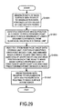
- the mask surface arrangement unit 513 obtains the center position of the mask surface 200 from the data storage unit 518 (step S61). At this stage, the mask surface arrangement unit 513 may calculate the center position of the mask surface 200 and store it into the data storage unit 518. The mask surface arrangement unit 513 then identifies, as the point of interest, the calculation point or the center point of an element closest to the center position of the mask surface 200 or the like from the numerical data storage unit 502, and stores the ID of the point of interest into the data storage unit 518 (step S63). The mask surface arrangement unit 513 calculates the distance using the coordinate values registered in FIGs.
- the mask surface arrangement unit 513 stores the ID of the identified calculation point as the ID of the point of interest.
- the center position of the mask surface 200 and the point of interest are correlated by the data in FIG. 23 and FIG. 25 .
- the mask surface arrangement unit 513 then arranges the mask surface 200 so that the coordinate values of the point of interest coincide with the coordinates of the center point in the mask surface 200 (step S65). More specifically, in order to make the coordinates of the point of interest coincide with the coordinates of the center point of the mask surface 200, the mask surface 200 is translated, and the calculation for this translation is carried out for all of the vertices of all of the polygons of the mask surface 200. As a result, the polygon data for the mask surface 200 after the translation is stored into the polygon data storage unit 514.
- the drawing instruction unit 515 outputs the data stored in the polygon data storage unit 514 and the data for the camera position and direction of the sight line, which is stored in the initial setting data storage unit 507 or the data storage unit 518, to the graphics processing unit 516 and causes the graphics processing unit 516 to execute the drawing (step S67) . Then, the processing returns the calling source processing.
- FIG. 26 the visualization data moving processing will be explained using FIG. 26 . Because the visualization data 100 and mask surface 200 arranged at a suitable position for the first numerical data have already been illustrated, the processing for displaying the second and subsequent visualization data 100 and mask surface 200 that is linked with the movement of the visualization data 100 will be explained below.
- the drawing instruction unit 515 sets "2" to the counter n (step S71).
- the visualization processing unit 512 carries out a visualization data generation processing using the numerical data at time n, and stores the resulting polygon data into the polygon data storage unit 514 (step S73) .
- the drawing instruction unit 515 outputs an instruction to the mask surface arrangement unit 513, and in response to this instruction, the mask surface arrangement unit 513 reads out the ID of the point of interest from the data storage unit 518, and further reads out the coordinates of the point of interest at time n from the numerical data storage unit 502 (step S75).
- the mask surface arrangement unit 513 arranges the mask surface 200 so that the coordinates of the point of interest coincide with the coordinates of the center of the mask surface 200 (step S77).
- the operations for translating the coordinates of the center of the mask surface 200 stored in the data storage unit 518 to the coordinates of the point of interest are carried out for all vertices of all polygons in the mask surface 200.
- the processing results are stored into the polygon data storage unit 514.
- the drawing instruction unit 515 outputs the data stored in the polygon data storage unit 514, and the data for the camera position and direction of the sight line, which is stored in the initial setting data storage unit 507 or data storage unit 518 to the graphics processing unit 516 (step S79) .
- the graphics processing unit 516 carries out the drawing onto the display device 517. As a result, the display for the time n is made as illustrated in FIG. 3 .
- the drawing instruction unit 515 determines whether the "n" has reached the maximum value for the "n” (step S81). For example, this determination is carried out by using the number of sets of numerical data stored in the numerical data storage unit 502 as the maximum value. When the "n" has not reached the maximum value of the "n”, the “n” is increased by "1" (step S83) and the processing returns to the step S73. On the other hand, when the "n" has reached the maximum value of the "n", the display is complete. Then, the processing returns to the calling source processing.
- the mask surface 200 follows that movement, so the portion of interest in the visualization data 100 is always arranged in front of the mask surface 200, thus being easy for the user to view.
- this technique is not limited to this.
- the system configuration as depicted in FIG. 5 may not be employed, and the processing from the numerical simulation to the visualization may be executed in one computer.
- the functional block diagram depicted in FIG. 6 is mere an example, and may not always correspond to the actual program module configuration.
- the order of the steps in the processing flow may be exchanged or plural steps may be executed in parallel.
- the visualization processing unit 512 may carry out the processing asynchronously with other processing units, and the processing result may be stored in the polygon data storage unit 514. Then, the drawing instruction unit 515 may read out the polygon data at arbitrary timing after the necessary processing is completed.
- center position of the mask surface 200 is linked with the position of the calculation point or the like.
- other position of the mask surface 200 such as a position designated by the user, may be linked with the position of the calculation point or the like.
- the visualization processing unit 512 may calculate data for a portion of the data stored in the numerical data storage unit 502 and store the calculated data into the numerical data storage unit 502.
- a solid mask surface 200 may be employed instead of the flat plane or curved surface.
- the aforementioned technique cannot treat this situation.
- virtual mask objects 210 and 220 are prepared and arranged at appropriate positions, and ⁇ value, which means "transparent", is set for a portion of the visualization 100, which is included in the virtual mask objects 210 and 220. Then, it becomes easy to see the portion 150 of interest in the visualization data 100, which is located between the virtual mask objects 210 and 220.
- the visualization data display processing apparatus 5 is a computer device as shown in FIG. 27 . That is, a memory 2501 (storage device), a CPU 2503 (processor), a hard disk drive (HDD) 2505, a display controller 2507 connected to a display device 2509, a drive device 2513 for a removable disk 2511, an input device 2515, and a communication controller 2517 for connection with a network are connected through a bus 2519 as shown in FIG. 27 .
- An operating system (OS) and an application program for carrying out the foregoing processing in the embodiment, are stored in the HDD 2505, and when executed by the CPU 2503, they are read out from the HDD 2505 to the memory 2501.
- OS operating system
- an application program for carrying out the foregoing processing in the embodiment are stored in the HDD 2505, and when executed by the CPU 2503, they are read out from the HDD 2505 to the memory 2501.
- the CPU 2503 controls the display controller 2507, the communication controller 2517, and the drive device 2513, and causes them to perform necessary operations. Besides, intermediate processing data is stored in the memory 2501, and if necessary, it is stored in the HDD 2505.
- the application program to realize the aforementioned functions is stored in the removable disk 2511 and distributed, and then it is installed into the HDD 2505 from the drive device 2513. It may be installed into the HDD 2505 via the network such as the Internet and the communication controller 2517.
- the hardware such as the CPU 2503 and the memory 2501, the OS and the necessary application programs systematically cooperate with each other, so that various functions as described above in details are realized.
- a portion or entire of the graphics processing unit 516 is implemented as hardware, and the display controller 2507 in FIG. 27 is partially included in the graphics processing unit 516.
- the mask surface follows the specific position of the visualization data, and even when the visualization data changes along the time base time, it becomes possible to easily grasp the portion of interest in the visualization data.
- the aforementioned generating may include generating data of the mask surface based on a range of the positions of the respective calculation points, which are stored in the numerical value data storage unit.
- the mask surface having the size by which the visualization data can be sufficiently covered is generated.
- the aforementioned generating include: calculating an appearance frequency of each calculation value, which is stored in the numerical value data storage unit; identifying a calculation value whose appearance frequency is maximum; associating a color range in a lookup table with an appearance range of the calculation values to identify a color associated with the identified calculation value; and setting a complementary color of the identified color as a color of the mask surface.
- a color making it easy to see the visualization data is set to the mask surface according to the color arrangement state for the visualization data.
- the ⁇ value of the aforementioned mask surface may be ununiform (non-uniform) on the mask surface.
- the ⁇ value of the mask surface may be set so as to increase or decrease transparency from a center of the mask surface to an outside. For example, when the transparency increases, it becomes possible to easily grasp the portion of much interest in the center portion.
- the aforementioned mask surface may be a curved surface.
- the curved surface or the like may appropriately hide the calculation points, depending on the distribution of the calculation points.
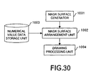
- a display processing apparatus of the visualization data includes: a mask surface generator (1001 in FIG. 30 ) to generate data of a mask surface with respect to visualization data for calculation values at respective calculation points, wherein the visualization data is arranged in a virtual three-dimensional space; a numerical value data storage unit (1003 in FIG. 30 ) storing, as time-series data, positions of the respective calculation points and calculation values at the respective calculation points; a mask surface arrangement unit (1002 in FIG.
- a mask processing method include: generating data of a mask surface for visualization data for calculation values at respective calculation points, wherein the visualization data is arranged in a virtual three-dimensional space; arranging the mask surface at a position away from a camera position by a predetermined distance in a direction of a sight line in the virtual three-dimensional space, according to data stored in a data storage unit (e.g. the initial setting data storage unit 507 and data storage unit 518 in FIG.
- a data storage unit e.g. the initial setting data storage unit 507 and data storage unit 518 in FIG.
- a program causing a computer to execute the aforementioned processing
- a program may be stored in a computer readable storage medium or storage device such as a flexible disk, CD-ROM, DVD-ROM, magneto-optic disk, a semiconductor memory, and hard disk.
- the intermediate processing result is temporarily stored in a storage device such as a main memory or the like.
Landscapes
- Engineering & Computer Science (AREA)
- Physics & Mathematics (AREA)
- Computer Graphics (AREA)
- General Physics & Mathematics (AREA)
- Theoretical Computer Science (AREA)
- Geometry (AREA)
- Image Generation (AREA)
- Processing Or Creating Images (AREA)
Claims (9)
- Programm zum Bewirken, dass ein Computer (5) einen Prozess ausführt, der umfasst:Erzeugen von Daten einer Maskenoberfläche (200) in Bezug auf Visualisierungsdaten (100) für jeweilige Berechnungspunkte, bei dem die Visualisierungsdaten in einem virtuellen dreidimensionalen Raum angeordnet sind, wobei jeder der Berechnungspunkte einen Berechnungswert hat und als Position in dem virtuellen dreidimensionalen Raum dargestellt wird;Identifizieren, von einer Zahlwertdatenspeichereinheit (4, 502), die als Zeitreihendaten Positionen der jeweiligen Berechnungspunkte und Berechnungswerte an den jeweiligen Berechnungspunkten speichert, eines ersten Punktes, dessen Position einem vorbestimmten Punkt auf der Maskenoberfläche (200) am nächsten ist;und für jede Einheitszeit in den Zeitreihendaten:Auslesen, von der Zahlenwertdatenspeichereinheit (4, 502), einer Position des identifizierten ersten Punktes; undAnordnen der Maskenoberfläche (200) auf der Basis einer Richtung einer Nutzersichtlinie und der Leseposition so, dass die Maskenoberfläche zu der Richtung der Nutzersichtlinie senkrecht ist und der vorbestimmte Punkt auf der Maskenoberfläche mit der Leseposition koinzidiert; undInstruieren, um Polygondaten bezüglich der Visualisierungsdaten (100) und Polygondaten bezüglich der Maskenoberfläche (200) in Zeitreihen zu zeichnen.
- Programm nach Anspruch 1, bei dem das Erzeugen das Erzeugen von Daten der Maskenoberfläche (200) auf der Basis eines Bereiches der Positionen der jeweiligen Berechnungspunkte umfasst, die in der Zahlenwertdatenspeichereinheit (4, 502) gespeichert sind.
- Programm nach Anspruch 1 oder 2, bei dem das Erzeugen umfasst:Berechnen einer Auftrittshäufigkeit jedes Berechnungswertes, der in der Zahlenwertdatenspeichereinheit (502) gespeichert ist;Identifizieren eines Berechnungswertes, dessen Auftrittshäufigkeit maximal ist;Zuordnen eines Farbereiches in einer Nachschlagtabelle (508) zu einem Auftrittsbereich der Berechnungswerte, um eine Farbe zu identifizieren, die dem identifizierten Berechnungswert zugeordnet ist; undFestlegen einer Komplementärfarbe der identifizierten Farbe als Farbe der Maskenoberfläche (200).
- Programm nach Anspruch 1, 2 oder 3, bei dem ein α-Wert der Maskenoberfläche (200) auf der Maskenoberfläche nicht gleichförmig ist.
- Programm nach einem vorhergehenden Anspruch, bei dem ein α-Wert der Maskenoberfläche (200) so festgelegt wird, um die Transparenz von einem Zentrum der Maskenoberfläche nach außen zu vergrößern oder zu verkleinern.
- Programm nach einem vorhergehenden Anspruch, bei dem die Maskenoberfläche (200) eine gekrümmte Oberfläche ist.
- Programm zum Bewirken, dass ein Computer einen Prozess ausführt, der umfasst:Erzeugen von Daten einer Maskenoberfläche (200) für Visualisierungsdaten (100) für jeweilige Berechnungspunkte, bei dem die Visualisierungsdaten in einem virtuellen dreidimensionalen Raum angeordnet sind, wobei jeder der Berechnungspunkte einen Berechnungswert hat und als Position in dem virtuellen dreidimensionalen Raum dargestellt wird;Anordnen der Maskenoberfläche (200) an einer Position, die von einer Kameraposition mit einer vorbestimmten Distanz in einer Richtung einer Sichtlinie in dem virtuellen dreidimensionalen Raum entfernt ist, gemäß Daten, die in einer Datenspeichereinheit (4, 502) gespeichert sind, die Daten der Kameraposition und die Richtung der Sichtlinie und Daten, die eine Anordnungsposition der Maskenoberfläche auf der Richtung der Sichtlinie definieren, speichert;Instruieren, um erste Polygondaten bezüglich der Visualisierungsdaten und zweite Polygondaten bezüglich der Maskenoberfläche (200) ohne Unterscheidung der ersten und zweiten Polygondaten zu zeichnen;Akzeptieren einer Veränderungsinstruktion von Daten, die die Anordnungsposition der Maskenoberfläche (200) definieren, von einem Nutzer und Aktualisieren von Daten bezüglich der Veränderungsinstruktion in der Datenspeichereinheit (4, 502); undAusführen des Anordnens und des Instruierens als Antwort auf das Akzeptieren und Aktualisieren.
- Maskenverarbeitungsverfahren, umfassend:Erzeugen, durch einen Computer (5), von Daten einer Maskenoberfläche (200) in Bezug auf Visualisierungsdaten für jeweilige Berechnungspunkte, bei dem die Visualisierungsdaten in einem virtuellen dreidimensionalen Raum angeordnet sind, wobei jeder der Berechnungspunkte einen Berechnungswert hat und als Position in dem virtuellen dreidimensionalen Raum dargestellt wird;Identifizieren, durch den Computer (5) und von einer Zahlwertdatenspeichereinheit (4, 502), die als Zeitreihendaten Positionen der jeweiligen Berechnungspunkte und Berechnungswerte an den jeweiligen Berechnungspunkten speichert, eines ersten Punktes, dessen Position einem vorbestimmten Punkt auf der Maskenoberfläche (200) am nächsten ist; unddurch den Computer (5) und für jede Einheitszeit in den Zeitreihendaten:Auslesen, von der Zahlenwertdatenspeichereinheit (4, 502), einer Position des identifizierten ersten Punktes;Anordnen der Maskenoberfläche (200) auf der Basis einer Richtung einer Nutzersichtlinie und der Leseposition so, dass die Maskenoberfläche zu der Richtung der Nutzersichtlinie senkrecht ist und der vorbestimmte Punkt auf der Maskenoberfläche mit der Leseposition koinzidiert; undInstruieren, um Polygondaten bezüglich der Visualisierungsdaten (100) und Polygondaten bezüglich der Maskenoberfläche (200) in Zeitreihen zu zeichnen.
- Anzeigeverarbeitungsvorrichtung, umfassend:eine erste Einheit (509), die angeordnet ist, um Daten einer Maskenoberfläche in Bezug auf Visualisierungsdaten für jeweilige Berechnungspunkte zu erzeugen, bei der die Visualisierungsdaten in einem virtuellen dreidimensionalen Raum angeordnet sind, wobei jeder der Berechnungspunkte einen Berechnungswert hat und als Position in dem virtuellen dreidimensionalen Raum dargestellt wird;eine Zahlwertdatenspeichereinheit (502), die zum Speichern von Positionen der jeweiligen Berechnungspunkte und Berechnungswerten an den jeweiligen Berechnungspunkten als Zeitreihendaten angeordnet ist;eine zweite Einheit (513), die angeordnet ist, um einen ersten Punkt zu identifizieren, dessen Position einem vorbestimmten Punkt auf der Maskenoberfläche am nächsten ist, und für jede Einheitszeit in den Zeitreihendaten von der Zahlenwertdatenspeichereinheit eine Position des identifizierten ersten Punktes auszulesen und die Maskenoberfläche auf der Basis einer Richtung einer Nutzersichtlinie und der Leseposition so anzuordnen, dass die Maskenoberfläche zu der Richtung der Nutzersichtlinie senkrecht ist und der vorbestimmte Punkt auf der Maskenoberfläche mit der Leseposition koinzidiert; undeine dritte Einheit (515), die angeordnet ist, um Polygondaten bezüglich der Visualisierungsdaten (100) und Polygondaten bezüglich der Maskenoberfläche (200) in Zeitreihen zu zeichnen.
Applications Claiming Priority (1)
| Application Number | Priority Date | Filing Date | Title |
|---|---|---|---|
| JP2010121829A JP5481751B2 (ja) | 2010-05-27 | 2010-05-27 | 隠蔽処理プログラム、可視化処理方法及び装置 |
Publications (2)
| Publication Number | Publication Date |
|---|---|
| EP2390843A1 EP2390843A1 (de) | 2011-11-30 |
| EP2390843B1 true EP2390843B1 (de) | 2013-01-09 |
Family
ID=44259603
Family Applications (1)
| Application Number | Title | Priority Date | Filing Date |
|---|---|---|---|
| EP11163832A Not-in-force EP2390843B1 (de) | 2010-05-27 | 2011-04-27 | Visualisierungsverarbeitungsverfahren und -vorrichtung |
Country Status (3)
| Country | Link |
|---|---|
| US (1) | US8743123B2 (de) |
| EP (1) | EP2390843B1 (de) |
| JP (1) | JP5481751B2 (de) |
Families Citing this family (2)
| Publication number | Priority date | Publication date | Assignee | Title |
|---|---|---|---|---|
| JP5907502B2 (ja) * | 2012-06-08 | 2016-04-26 | 富士通株式会社 | 表示プログラム、表示方法、および表示装置 |
| JP6349908B2 (ja) * | 2014-04-22 | 2018-07-04 | 富士通株式会社 | データ処理方法、データ処理装置及びプログラム |
Family Cites Families (24)
| Publication number | Priority date | Publication date | Assignee | Title |
|---|---|---|---|---|
| JPS63298489A (ja) * | 1987-05-28 | 1988-12-06 | Matsushita Electric Ind Co Ltd | 隠れ面処理装置 |
| JPH02197965A (ja) * | 1989-01-27 | 1990-08-06 | Babcock Hitachi Kk | 3次元の解析データを図形として表示する方法 |
| US5113490A (en) * | 1989-06-19 | 1992-05-12 | Silicon Graphics, Inc. | Method for forming a computer model from an intersection of a cutting surface with a bounded volume |
| JPH0540951A (ja) | 1991-06-25 | 1993-02-19 | Canon Inc | トラツキング用回動ミラー装置 |
| JPH0540951U (ja) * | 1991-11-06 | 1993-06-01 | 日本電気ソフトウエア株式会社 | 焦点機能付グラフイツク端末と焦点機能付イメージ処理装置 |
| JP2792376B2 (ja) | 1993-02-02 | 1998-09-03 | 松下電器産業株式会社 | 画像ぼかし処理装置 |
| JP3739829B2 (ja) * | 1995-05-22 | 2006-01-25 | 富士通株式会社 | グラフィックス装置 |
| US6373483B1 (en) * | 1997-01-13 | 2002-04-16 | Silicon Graphics, Inc. | Method, system and computer program product for visually approximating scattered data using color to represent values of a categorical variable |
| JP3383563B2 (ja) * | 1997-12-18 | 2003-03-04 | 富士通株式会社 | 物体移動シミュレーション装置 |
| US6310620B1 (en) * | 1998-12-22 | 2001-10-30 | Terarecon, Inc. | Method and apparatus for volume rendering with multiple depth buffers |
| JP2000354257A (ja) | 1999-06-10 | 2000-12-19 | Sony Corp | 画像処理装置、画像処理方法、およびプログラム提供媒体 |
| AU2001239926A1 (en) * | 2000-02-25 | 2001-09-03 | The Research Foundation Of State University Of New York | Apparatus and method for volume processing and rendering |
| JP2002136519A (ja) | 2000-11-02 | 2002-05-14 | Nippon Koden Corp | 三次元画像表示方法及びその装置 |
| JP3639286B2 (ja) | 2003-09-25 | 2005-04-20 | コナミ株式会社 | ゲームプログラム、及びゲーム装置 |
| JP3914973B2 (ja) | 2003-11-27 | 2007-05-16 | 防衛省技術研究本部長 | 画像の動き検出装置 |
| JP3877077B2 (ja) * | 2004-08-31 | 2007-02-07 | 任天堂株式会社 | ゲーム装置および画像処理プログラム |
| JP4882288B2 (ja) * | 2005-06-20 | 2012-02-22 | 富士ゼロックス株式会社 | 表示制御装置、システム及び表示制御方法 |
| JP2007066055A (ja) * | 2005-08-31 | 2007-03-15 | Ritsumeikan | 3次元オブジェクト内で3次元的に分布するテンソル量を表示するコンピュータプログラム及びテンソル量表示画像データ生成方法 |
| US7839404B2 (en) * | 2006-07-25 | 2010-11-23 | Siemens Medical Solutions Usa, Inc. | Systems and methods of direct volume rendering |
| US7978195B2 (en) * | 2007-07-02 | 2011-07-12 | Hyperformix, Inc. | Method for superimposing statistical information on tabular data |
| US7978191B2 (en) * | 2007-09-24 | 2011-07-12 | Dolphin Imaging Systems, Llc | System and method for locating anatomies of interest in a 3D volume |
| JP2009160306A (ja) * | 2008-01-09 | 2009-07-23 | Ziosoft Inc | 画像表示装置、画像表示装置の制御方法、および画像表示装置の制御プログラム |
| WO2010070532A2 (en) * | 2008-12-16 | 2010-06-24 | Koninklijke Philips Electronics N.V. | Positioning a cut plane in respect of a three-dimensional image |
| US9177416B2 (en) * | 2010-03-22 | 2015-11-03 | Microsoft Technology Licensing, Llc | Space skipping for multi-dimensional image rendering |
-
2010
- 2010-05-27 JP JP2010121829A patent/JP5481751B2/ja not_active Expired - Fee Related
-
2011
- 2011-04-27 EP EP11163832A patent/EP2390843B1/de not_active Not-in-force
- 2011-05-19 US US13/110,996 patent/US8743123B2/en active Active
Also Published As
| Publication number | Publication date |
|---|---|
| US20110292039A1 (en) | 2011-12-01 |
| JP2011248675A (ja) | 2011-12-08 |
| US8743123B2 (en) | 2014-06-03 |
| JP5481751B2 (ja) | 2014-04-23 |
| EP2390843A1 (de) | 2011-11-30 |
Similar Documents
| Publication | Publication Date | Title |
|---|---|---|
| US7983473B2 (en) | Transparency adjustment of a presentation | |
| US8154544B1 (en) | User specified contact deformations for computer graphics | |
| US20190130599A1 (en) | Systems and methods for determining when to provide eye contact from an avatar to a user viewing a virtual environment | |
| US10719912B2 (en) | Scaling and feature retention in graphical elements defined based on functions | |
| US20190130631A1 (en) | Systems and methods for determining how to render a virtual object based on one or more conditions | |
| JP7614801B2 (ja) | 画像処理装置、画像処理方法及びプログラム | |
| JP5047124B2 (ja) | パーツ識別画像作成装置及び同方法、パーツ識別表示装置及び同方法、プログラム及び記憶媒体 | |
| US20120299910A1 (en) | Z-culling method, three-dimensional graphics processing method and apparatus threrof | |
| JP2012190428A (ja) | 立体映像視覚効果処理方法 | |
| CN112184873B (zh) | 分形图形创建方法、装置、电子设备和存储介质 | |
| US10535188B2 (en) | Tessellation edge shaders | |
| CN107015654A (zh) | 基于增强现实的导航方法及装置 | |
| JP5195641B2 (ja) | ハーネス検証装置およびハーネス検証プログラム | |
| EP4660954A1 (de) | Bildanzeigeverfahren für virtuelle szene, vorrichtung, medium und programmprodukt | |
| RU2427918C2 (ru) | Метафора двумерного редактирования для трехмерной графики | |
| JP2008282171A (ja) | グラフィックスプロセッサおよび描画処理方法 | |
| US8743123B2 (en) | Visualization processing method and apparatus with mask surface | |
| KR101227155B1 (ko) | 저해상도 그래픽 영상을 고해상도 그래픽 영상으로 실시간 변환하는 그래픽 영상 처리 장치 및 방법 | |
| CN118397226A (zh) | 一种三维模型确定方法及电子设备 | |
| CN111862338B (zh) | 模拟眼镜佩戴图像的显示方法及装置 | |
| JP2011198138A (ja) | 漫画作成支援装置、漫画作成支援方法およびプログラム | |
| KR100848687B1 (ko) | 3차원 그래픽 처리 장치 및 그것의 동작 방법 | |
| TW201401219A (zh) | 用於隨機柵格化之彈性散焦模糊的技術 | |
| CN116188668B (zh) | 一种基于ios平台的阴影渲染的方法、介质及电子设备 | |
| KR100914915B1 (ko) | 저비용의 뷰-체적 클리핑 방법 및 장치 |
Legal Events
| Date | Code | Title | Description |
|---|---|---|---|
| AK | Designated contracting states |
Kind code of ref document: A1 Designated state(s): AL AT BE BG CH CY CZ DE DK EE ES FI FR GB GR HR HU IE IS IT LI LT LU LV MC MK MT NL NO PL PT RO RS SE SI SK SM TR |
|
| AX | Request for extension of the european patent |
Extension state: BA ME |
|
| PUAI | Public reference made under article 153(3) epc to a published international application that has entered the european phase |
Free format text: ORIGINAL CODE: 0009012 |
|
| 17P | Request for examination filed |
Effective date: 20120523 |
|
| GRAP | Despatch of communication of intention to grant a patent |
Free format text: ORIGINAL CODE: EPIDOSNIGR1 |
|
| GRAS | Grant fee paid |
Free format text: ORIGINAL CODE: EPIDOSNIGR3 |
|
| GRAA | (expected) grant |
Free format text: ORIGINAL CODE: 0009210 |
|
| AK | Designated contracting states |
Kind code of ref document: B1 Designated state(s): AL AT BE BG CH CY CZ DE DK EE ES FI FR GB GR HR HU IE IS IT LI LT LU LV MC MK MT NL NO PL PT RO RS SE SI SK SM TR |
|
| REG | Reference to a national code |
Ref country code: GB Ref legal event code: FG4D |
|
| REG | Reference to a national code |
Ref country code: AT Ref legal event code: REF Ref document number: 593142 Country of ref document: AT Kind code of ref document: T Effective date: 20130115 Ref country code: CH Ref legal event code: EP |
|
| REG | Reference to a national code |
Ref country code: IE Ref legal event code: FG4D |
|
| REG | Reference to a national code |
Ref country code: DE Ref legal event code: R096 Ref document number: 602011000690 Country of ref document: DE Effective date: 20130314 |
|
| PG25 | Lapsed in a contracting state [announced via postgrant information from national office to epo] |
Ref country code: SI Free format text: LAPSE BECAUSE OF FAILURE TO SUBMIT A TRANSLATION OF THE DESCRIPTION OR TO PAY THE FEE WITHIN THE PRESCRIBED TIME-LIMIT Effective date: 20130109 |
|
| REG | Reference to a national code |
Ref country code: NL Ref legal event code: VDEP Effective date: 20130109 |
|
| REG | Reference to a national code |
Ref country code: AT Ref legal event code: MK05 Ref document number: 593142 Country of ref document: AT Kind code of ref document: T Effective date: 20130109 |
|
| REG | Reference to a national code |
Ref country code: LT Ref legal event code: MG4D |
|
| PG25 | Lapsed in a contracting state [announced via postgrant information from national office to epo] |
Ref country code: SE Free format text: LAPSE BECAUSE OF FAILURE TO SUBMIT A TRANSLATION OF THE DESCRIPTION OR TO PAY THE FEE WITHIN THE PRESCRIBED TIME-LIMIT Effective date: 20130109 Ref country code: IS Free format text: LAPSE BECAUSE OF FAILURE TO SUBMIT A TRANSLATION OF THE DESCRIPTION OR TO PAY THE FEE WITHIN THE PRESCRIBED TIME-LIMIT Effective date: 20130509 Ref country code: NO Free format text: LAPSE BECAUSE OF FAILURE TO SUBMIT A TRANSLATION OF THE DESCRIPTION OR TO PAY THE FEE WITHIN THE PRESCRIBED TIME-LIMIT Effective date: 20130409 Ref country code: BG Free format text: LAPSE BECAUSE OF FAILURE TO SUBMIT A TRANSLATION OF THE DESCRIPTION OR TO PAY THE FEE WITHIN THE PRESCRIBED TIME-LIMIT Effective date: 20130409 Ref country code: LT Free format text: LAPSE BECAUSE OF FAILURE TO SUBMIT A TRANSLATION OF THE DESCRIPTION OR TO PAY THE FEE WITHIN THE PRESCRIBED TIME-LIMIT Effective date: 20130109 Ref country code: AT Free format text: LAPSE BECAUSE OF FAILURE TO SUBMIT A TRANSLATION OF THE DESCRIPTION OR TO PAY THE FEE WITHIN THE PRESCRIBED TIME-LIMIT Effective date: 20130109 Ref country code: ES Free format text: LAPSE BECAUSE OF FAILURE TO SUBMIT A TRANSLATION OF THE DESCRIPTION OR TO PAY THE FEE WITHIN THE PRESCRIBED TIME-LIMIT Effective date: 20130420 Ref country code: BE Free format text: LAPSE BECAUSE OF FAILURE TO SUBMIT A TRANSLATION OF THE DESCRIPTION OR TO PAY THE FEE WITHIN THE PRESCRIBED TIME-LIMIT Effective date: 20130109 |
|
| PG25 | Lapsed in a contracting state [announced via postgrant information from national office to epo] |
Ref country code: PL Free format text: LAPSE BECAUSE OF FAILURE TO SUBMIT A TRANSLATION OF THE DESCRIPTION OR TO PAY THE FEE WITHIN THE PRESCRIBED TIME-LIMIT Effective date: 20130109 Ref country code: FI Free format text: LAPSE BECAUSE OF FAILURE TO SUBMIT A TRANSLATION OF THE DESCRIPTION OR TO PAY THE FEE WITHIN THE PRESCRIBED TIME-LIMIT Effective date: 20130109 Ref country code: LV Free format text: LAPSE BECAUSE OF FAILURE TO SUBMIT A TRANSLATION OF THE DESCRIPTION OR TO PAY THE FEE WITHIN THE PRESCRIBED TIME-LIMIT Effective date: 20130109 Ref country code: PT Free format text: LAPSE BECAUSE OF FAILURE TO SUBMIT A TRANSLATION OF THE DESCRIPTION OR TO PAY THE FEE WITHIN THE PRESCRIBED TIME-LIMIT Effective date: 20130509 Ref country code: GR Free format text: LAPSE BECAUSE OF FAILURE TO SUBMIT A TRANSLATION OF THE DESCRIPTION OR TO PAY THE FEE WITHIN THE PRESCRIBED TIME-LIMIT Effective date: 20130410 Ref country code: NL Free format text: LAPSE BECAUSE OF FAILURE TO SUBMIT A TRANSLATION OF THE DESCRIPTION OR TO PAY THE FEE WITHIN THE PRESCRIBED TIME-LIMIT Effective date: 20130109 |
|
| PG25 | Lapsed in a contracting state [announced via postgrant information from national office to epo] |
Ref country code: HR Free format text: LAPSE BECAUSE OF FAILURE TO SUBMIT A TRANSLATION OF THE DESCRIPTION OR TO PAY THE FEE WITHIN THE PRESCRIBED TIME-LIMIT Effective date: 20130109 Ref country code: RS Free format text: LAPSE BECAUSE OF FAILURE TO SUBMIT A TRANSLATION OF THE DESCRIPTION OR TO PAY THE FEE WITHIN THE PRESCRIBED TIME-LIMIT Effective date: 20130109 |
|
| PG25 | Lapsed in a contracting state [announced via postgrant information from national office to epo] |
Ref country code: DK Free format text: LAPSE BECAUSE OF FAILURE TO SUBMIT A TRANSLATION OF THE DESCRIPTION OR TO PAY THE FEE WITHIN THE PRESCRIBED TIME-LIMIT Effective date: 20130109 Ref country code: CZ Free format text: LAPSE BECAUSE OF FAILURE TO SUBMIT A TRANSLATION OF THE DESCRIPTION OR TO PAY THE FEE WITHIN THE PRESCRIBED TIME-LIMIT Effective date: 20130109 Ref country code: EE Free format text: LAPSE BECAUSE OF FAILURE TO SUBMIT A TRANSLATION OF THE DESCRIPTION OR TO PAY THE FEE WITHIN THE PRESCRIBED TIME-LIMIT Effective date: 20130109 Ref country code: RO Free format text: LAPSE BECAUSE OF FAILURE TO SUBMIT A TRANSLATION OF THE DESCRIPTION OR TO PAY THE FEE WITHIN THE PRESCRIBED TIME-LIMIT Effective date: 20130109 Ref country code: SK Free format text: LAPSE BECAUSE OF FAILURE TO SUBMIT A TRANSLATION OF THE DESCRIPTION OR TO PAY THE FEE WITHIN THE PRESCRIBED TIME-LIMIT Effective date: 20130109 |
|
| PLBE | No opposition filed within time limit |
Free format text: ORIGINAL CODE: 0009261 |
|
| STAA | Information on the status of an ep patent application or granted ep patent |
Free format text: STATUS: NO OPPOSITION FILED WITHIN TIME LIMIT |
|
| PG25 | Lapsed in a contracting state [announced via postgrant information from national office to epo] |
Ref country code: MC Free format text: LAPSE BECAUSE OF FAILURE TO SUBMIT A TRANSLATION OF THE DESCRIPTION OR TO PAY THE FEE WITHIN THE PRESCRIBED TIME-LIMIT Effective date: 20130109 Ref country code: CY Free format text: LAPSE BECAUSE OF FAILURE TO SUBMIT A TRANSLATION OF THE DESCRIPTION OR TO PAY THE FEE WITHIN THE PRESCRIBED TIME-LIMIT Effective date: 20130109 |
|
| 26N | No opposition filed |
Effective date: 20131010 |
|
| PG25 | Lapsed in a contracting state [announced via postgrant information from national office to epo] |
Ref country code: IT Free format text: LAPSE BECAUSE OF FAILURE TO SUBMIT A TRANSLATION OF THE DESCRIPTION OR TO PAY THE FEE WITHIN THE PRESCRIBED TIME-LIMIT Effective date: 20130109 |
|
| REG | Reference to a national code |
Ref country code: IE Ref legal event code: MM4A |
|
| REG | Reference to a national code |
Ref country code: DE Ref legal event code: R097 Ref document number: 602011000690 Country of ref document: DE Effective date: 20131010 |
|
| PG25 | Lapsed in a contracting state [announced via postgrant information from national office to epo] |
Ref country code: IE Free format text: LAPSE BECAUSE OF NON-PAYMENT OF DUE FEES Effective date: 20130427 |
|
| REG | Reference to a national code |
Ref country code: CH Ref legal event code: PL |
|
| PG25 | Lapsed in a contracting state [announced via postgrant information from national office to epo] |
Ref country code: LI Free format text: LAPSE BECAUSE OF NON-PAYMENT OF DUE FEES Effective date: 20140430 Ref country code: CH Free format text: LAPSE BECAUSE OF NON-PAYMENT OF DUE FEES Effective date: 20140430 |
|
| PG25 | Lapsed in a contracting state [announced via postgrant information from national office to epo] |
Ref country code: MT Free format text: LAPSE BECAUSE OF FAILURE TO SUBMIT A TRANSLATION OF THE DESCRIPTION OR TO PAY THE FEE WITHIN THE PRESCRIBED TIME-LIMIT Effective date: 20130109 |
|
| PG25 | Lapsed in a contracting state [announced via postgrant information from national office to epo] |
Ref country code: SM Free format text: LAPSE BECAUSE OF FAILURE TO SUBMIT A TRANSLATION OF THE DESCRIPTION OR TO PAY THE FEE WITHIN THE PRESCRIBED TIME-LIMIT Effective date: 20130109 |
|
| PG25 | Lapsed in a contracting state [announced via postgrant information from national office to epo] |
Ref country code: TR Free format text: LAPSE BECAUSE OF FAILURE TO SUBMIT A TRANSLATION OF THE DESCRIPTION OR TO PAY THE FEE WITHIN THE PRESCRIBED TIME-LIMIT Effective date: 20130109 |
|
| PG25 | Lapsed in a contracting state [announced via postgrant information from national office to epo] |
Ref country code: HU Free format text: LAPSE BECAUSE OF FAILURE TO SUBMIT A TRANSLATION OF THE DESCRIPTION OR TO PAY THE FEE WITHIN THE PRESCRIBED TIME-LIMIT; INVALID AB INITIO Effective date: 20110427 Ref country code: MK Free format text: LAPSE BECAUSE OF FAILURE TO SUBMIT A TRANSLATION OF THE DESCRIPTION OR TO PAY THE FEE WITHIN THE PRESCRIBED TIME-LIMIT Effective date: 20130109 Ref country code: LU Free format text: LAPSE BECAUSE OF NON-PAYMENT OF DUE FEES Effective date: 20130427 |
|
| REG | Reference to a national code |
Ref country code: FR Ref legal event code: PLFP Year of fee payment: 6 |
|
| REG | Reference to a national code |
Ref country code: FR Ref legal event code: PLFP Year of fee payment: 7 |
|
| REG | Reference to a national code |
Ref country code: FR Ref legal event code: PLFP Year of fee payment: 8 |
|
| PG25 | Lapsed in a contracting state [announced via postgrant information from national office to epo] |
Ref country code: AL Free format text: LAPSE BECAUSE OF FAILURE TO SUBMIT A TRANSLATION OF THE DESCRIPTION OR TO PAY THE FEE WITHIN THE PRESCRIBED TIME-LIMIT Effective date: 20130109 |
|
| PGFP | Annual fee paid to national office [announced via postgrant information from national office to epo] |
Ref country code: GB Payment date: 20220303 Year of fee payment: 12 |
|
| PGFP | Annual fee paid to national office [announced via postgrant information from national office to epo] |
Ref country code: FR Payment date: 20220308 Year of fee payment: 12 |
|
| PGFP | Annual fee paid to national office [announced via postgrant information from national office to epo] |
Ref country code: DE Payment date: 20220302 Year of fee payment: 12 |
|
| REG | Reference to a national code |
Ref country code: DE Ref legal event code: R119 Ref document number: 602011000690 Country of ref document: DE |
|
| GBPC | Gb: european patent ceased through non-payment of renewal fee |
Effective date: 20230427 |
|
| PG25 | Lapsed in a contracting state [announced via postgrant information from national office to epo] |
Ref country code: GB Free format text: LAPSE BECAUSE OF NON-PAYMENT OF DUE FEES Effective date: 20230427 |
|
| PG25 | Lapsed in a contracting state [announced via postgrant information from national office to epo] |
Ref country code: GB Free format text: LAPSE BECAUSE OF NON-PAYMENT OF DUE FEES Effective date: 20230427 Ref country code: FR Free format text: LAPSE BECAUSE OF NON-PAYMENT OF DUE FEES Effective date: 20230430 Ref country code: DE Free format text: LAPSE BECAUSE OF NON-PAYMENT OF DUE FEES Effective date: 20231103 |