EP2390637A1 - Standardspektroradiometer - Google Patents
Standardspektroradiometer Download PDFInfo
- Publication number
- EP2390637A1 EP2390637A1 EP10733563A EP10733563A EP2390637A1 EP 2390637 A1 EP2390637 A1 EP 2390637A1 EP 10733563 A EP10733563 A EP 10733563A EP 10733563 A EP10733563 A EP 10733563A EP 2390637 A1 EP2390637 A1 EP 2390637A1
- Authority
- EP
- European Patent Office
- Prior art keywords
- time
- pulse
- solar simulator
- type solar
- light emission
- Prior art date
- Legal status (The legal status is an assumption and is not a legal conclusion. Google has not performed a legal analysis and makes no representation as to the accuracy of the status listed.)
- Withdrawn
Links
- 238000005259 measurement Methods 0.000 claims abstract description 54
- 230000003595 spectral effect Effects 0.000 claims abstract description 36
- 238000001514 detection method Methods 0.000 claims abstract description 27
- 239000013307 optical fiber Substances 0.000 claims abstract description 7
- 239000006185 dispersion Substances 0.000 claims abstract description 5
- 238000001228 spectrum Methods 0.000 claims description 7
- 230000003287 optical effect Effects 0.000 claims description 5
- 230000005856 abnormality Effects 0.000 claims description 4
- 230000005855 radiation Effects 0.000 abstract description 20
- 238000010586 diagram Methods 0.000 description 8
- 238000004519 manufacturing process Methods 0.000 description 4
- 230000002159 abnormal effect Effects 0.000 description 1
- 239000003990 capacitor Substances 0.000 description 1
- 230000015556 catabolic process Effects 0.000 description 1
- 238000006731 degradation reaction Methods 0.000 description 1
- 238000003745 diagnosis Methods 0.000 description 1
- 230000000694 effects Effects 0.000 description 1
- 238000000295 emission spectrum Methods 0.000 description 1
- 238000011156 evaluation Methods 0.000 description 1
- 230000006870 function Effects 0.000 description 1
- 238000012544 monitoring process Methods 0.000 description 1
- 238000010248 power generation Methods 0.000 description 1
- 230000035484 reaction time Effects 0.000 description 1
- 238000010792 warming Methods 0.000 description 1
Images




Classifications
-
- G—PHYSICS
- G01—MEASURING; TESTING
- G01J—MEASUREMENT OF INTENSITY, VELOCITY, SPECTRAL CONTENT, POLARISATION, PHASE OR PULSE CHARACTERISTICS OF INFRARED, VISIBLE OR ULTRAVIOLET LIGHT; COLORIMETRY; RADIATION PYROMETRY
- G01J3/00—Spectrometry; Spectrophotometry; Monochromators; Measuring colours
- G01J3/28—Investigating the spectrum
- G01J3/443—Emission spectrometry
-
- G—PHYSICS
- G01—MEASURING; TESTING
- G01J—MEASUREMENT OF INTENSITY, VELOCITY, SPECTRAL CONTENT, POLARISATION, PHASE OR PULSE CHARACTERISTICS OF INFRARED, VISIBLE OR ULTRAVIOLET LIGHT; COLORIMETRY; RADIATION PYROMETRY
- G01J1/00—Photometry, e.g. photographic exposure meter
- G01J1/42—Photometry, e.g. photographic exposure meter using electric radiation detectors
- G01J1/4257—Photometry, e.g. photographic exposure meter using electric radiation detectors applied to monitoring the characteristics of a beam, e.g. laser beam, headlamp beam
-
- G—PHYSICS
- G01—MEASURING; TESTING
- G01J—MEASUREMENT OF INTENSITY, VELOCITY, SPECTRAL CONTENT, POLARISATION, PHASE OR PULSE CHARACTERISTICS OF INFRARED, VISIBLE OR ULTRAVIOLET LIGHT; COLORIMETRY; RADIATION PYROMETRY
- G01J11/00—Measuring the characteristics of individual optical pulses or of optical pulse trains
-
- G—PHYSICS
- G01—MEASURING; TESTING
- G01J—MEASUREMENT OF INTENSITY, VELOCITY, SPECTRAL CONTENT, POLARISATION, PHASE OR PULSE CHARACTERISTICS OF INFRARED, VISIBLE OR ULTRAVIOLET LIGHT; COLORIMETRY; RADIATION PYROMETRY
- G01J3/00—Spectrometry; Spectrophotometry; Monochromators; Measuring colours
- G01J3/02—Details
-
- G—PHYSICS
- G01—MEASURING; TESTING
- G01J—MEASUREMENT OF INTENSITY, VELOCITY, SPECTRAL CONTENT, POLARISATION, PHASE OR PULSE CHARACTERISTICS OF INFRARED, VISIBLE OR ULTRAVIOLET LIGHT; COLORIMETRY; RADIATION PYROMETRY
- G01J3/00—Spectrometry; Spectrophotometry; Monochromators; Measuring colours
- G01J3/02—Details
- G01J3/0205—Optical elements not provided otherwise, e.g. optical manifolds, diffusers, windows
- G01J3/0218—Optical elements not provided otherwise, e.g. optical manifolds, diffusers, windows using optical fibers
-
- G—PHYSICS
- G01—MEASURING; TESTING
- G01J—MEASUREMENT OF INTENSITY, VELOCITY, SPECTRAL CONTENT, POLARISATION, PHASE OR PULSE CHARACTERISTICS OF INFRARED, VISIBLE OR ULTRAVIOLET LIGHT; COLORIMETRY; RADIATION PYROMETRY
- G01J3/00—Spectrometry; Spectrophotometry; Monochromators; Measuring colours
- G01J3/02—Details
- G01J3/0264—Electrical interface; User interface
-
- G—PHYSICS
- G01—MEASURING; TESTING
- G01J—MEASUREMENT OF INTENSITY, VELOCITY, SPECTRAL CONTENT, POLARISATION, PHASE OR PULSE CHARACTERISTICS OF INFRARED, VISIBLE OR ULTRAVIOLET LIGHT; COLORIMETRY; RADIATION PYROMETRY
- G01J3/00—Spectrometry; Spectrophotometry; Monochromators; Measuring colours
- G01J3/02—Details
- G01J3/027—Control of working procedures of a spectrometer; Failure detection; Bandwidth calculation
-
- G—PHYSICS
- G01—MEASURING; TESTING
- G01J—MEASUREMENT OF INTENSITY, VELOCITY, SPECTRAL CONTENT, POLARISATION, PHASE OR PULSE CHARACTERISTICS OF INFRARED, VISIBLE OR ULTRAVIOLET LIGHT; COLORIMETRY; RADIATION PYROMETRY
- G01J3/00—Spectrometry; Spectrophotometry; Monochromators; Measuring colours
- G01J3/28—Investigating the spectrum
- G01J3/30—Measuring the intensity of spectral lines directly on the spectrum itself
- G01J3/36—Investigating two or more bands of a spectrum by separate detectors
-
- H—ELECTRICITY
- H02—GENERATION; CONVERSION OR DISTRIBUTION OF ELECTRIC POWER
- H02S—GENERATION OF ELECTRIC POWER BY CONVERSION OF INFRARED RADIATION, VISIBLE LIGHT OR ULTRAVIOLET LIGHT, e.g. USING PHOTOVOLTAIC [PV] MODULES
- H02S50/00—Monitoring or testing of PV systems, e.g. load balancing or fault identification
- H02S50/10—Testing of PV devices, e.g. of PV modules or single PV cells
-
- G—PHYSICS
- G01—MEASURING; TESTING
- G01J—MEASUREMENT OF INTENSITY, VELOCITY, SPECTRAL CONTENT, POLARISATION, PHASE OR PULSE CHARACTERISTICS OF INFRARED, VISIBLE OR ULTRAVIOLET LIGHT; COLORIMETRY; RADIATION PYROMETRY
- G01J1/00—Photometry, e.g. photographic exposure meter
- G01J1/42—Photometry, e.g. photographic exposure meter using electric radiation detectors
- G01J2001/4238—Pulsed light
-
- G—PHYSICS
- G01—MEASURING; TESTING
- G01J—MEASUREMENT OF INTENSITY, VELOCITY, SPECTRAL CONTENT, POLARISATION, PHASE OR PULSE CHARACTERISTICS OF INFRARED, VISIBLE OR ULTRAVIOLET LIGHT; COLORIMETRY; RADIATION PYROMETRY
- G01J1/00—Photometry, e.g. photographic exposure meter
- G01J1/42—Photometry, e.g. photographic exposure meter using electric radiation detectors
- G01J2001/4247—Photometry, e.g. photographic exposure meter using electric radiation detectors for testing lamps or other light sources
-
- Y—GENERAL TAGGING OF NEW TECHNOLOGICAL DEVELOPMENTS; GENERAL TAGGING OF CROSS-SECTIONAL TECHNOLOGIES SPANNING OVER SEVERAL SECTIONS OF THE IPC; TECHNICAL SUBJECTS COVERED BY FORMER USPC CROSS-REFERENCE ART COLLECTIONS [XRACs] AND DIGESTS
- Y02—TECHNOLOGIES OR APPLICATIONS FOR MITIGATION OR ADAPTATION AGAINST CLIMATE CHANGE
- Y02E—REDUCTION OF GREENHOUSE GAS [GHG] EMISSIONS, RELATED TO ENERGY GENERATION, TRANSMISSION OR DISTRIBUTION
- Y02E10/00—Energy generation through renewable energy sources
- Y02E10/50—Photovoltaic [PV] energy
Definitions
- the present invention relates to a standard spectroradiometer and, particularly to, a standard spectroradiometer for measuring spectral radiation characteristics of flashlights emitted from various flash lamps for a pulse-lighting type solar simulator, for a camera, for medical use, for printing, for ultraviolet curing and the like.
- FIG. 2 is a diagram illustrating a configuration of a spectroradiometer 100 for measuring pulse light emission of a pulse-lighting type solar simulator 101 according to the prior art.
- pulse light emission from a discharge lamp 1011 of the pulse-lighting type solar simulator 101 is received by an optical fiber 104 via an incident optical system 103 including a transmission-type diffuser plate 102, then introduced into optical fibers 1061, 1062, ... 1065 suitable for characteristics of wavelengths ⁇ 1, ⁇ 2, ...
- Detectors 1081, 1082, ... 1085 included in the respective spectroscope 1071, 1072, ... 1075 are intended for measuring the spectral radiation characteristic of the pulse-lighting type solar simulator in synchronization with a trigger signal for pulse-lighting the discharge lamp 1011 of the pulse-lighting type solar simulator 101, according to the measurement start signal emitted in a short time of pulse light emission.
- the detectors 1081, 1082 ... 1085 it is difficult for the detectors 1081, 1082 ... 1085 to accurately measure the spectral radiation characteristic of pulse light emission. This is not only because the pulse light emission time is short, but also because the timing of light emission sometimes varies in a range of about several tens to 100 ⁇ sec since the discharge lamp 1011 used in the pulse-lighting type solar simulator 101 releases electric charges charged in a not-illustrated capacitor by discharge between lamp electrodes to emit light. In other words, the timing from the time when the trigger signal for lighting the discharge lamp 1011 is emitted to the time when the discharge lamp 1011 actually emits light varies. Another problem is that accurate measurement of the spectral radiation characteristic cannot be performed for the discharge lamp 1011 having a short light emission time if the measurement timing is deviated.
- the detectors 1081, 1082 ... 1085 in an array-form are attached to the spectroscopes 1071, 1072, ... 1075, and the detectors 1081, 1082 ... 1085 measure and record the spectra of the discharge lamp 1011 in synchronization with the trigger signal for lighting the discharge lamp 1011, according to the measurement start signal.
- the discharge lamp 1011 varies in time period required from the time when the trigger signal for starting light emission is received to the time when the discharge lamp 1011 actually emits light, and thus has a problem that timings of the actual light emission and measurement are deviated from each other and measurement needs to be repeatedly performed a number of times.
- the lighting time of the discharge lamp 1011 is short, measurement of spectra by the detectors 1081, 1082 ... 1085 needs to be performed immediately after the trigger signal is received.
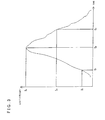
- Fig. 3 is a diagram illustrating an example of a light emission pattern of a short-pulse type solar simulator.
- This light emission pattern is a light emission pattern when light received from a pulse-lighting type solar simulator is received by a photo-detector without dispersion, and this light emission pattern translates in a time axis direction but its waveform itself is almost fixed.
- This drawing illustrates that an intensity I1 is at a time t1 at start of pulse lighting, an intensity I2 is at a peak time t2, and an intensity I3 is at a time t3 after the peak time t2 of the intensity, and the spectral radiation characteristic of light at the peak time t2 are to be measured by the spectroradiometer.
- the characteristic at the peak time t2 is generally different from the spectral radiation characteristics at non-peak times such as t1 and t3. In short, if the measurement timing is deviated from t2, a right spectral radiation characteristic when measuring the solar cell cannot be obtained.
- Fig. 4 is a diagram illustrating an example of a light emission pattern of a long-pulse type solar simulator. Unlike the light emission pattern of the short-pulse type solar simulator, a long and flat peak part continues. The time period from the time when light is emitted to the time when the light reaches the peak part also varies depending on the kind of the pulse-lighting type solar simulator, bringing about a problem that it is difficult to perform measurement at the optimum timing.
- Fig. 5 is a graph illustrating a measurement result of a spectral radiation characteristic of a pulse-type solar simulator by a spectroradiometer according to the prior art. As illustrated in the drawing, there occurs a measurement error because of measurement at an inappropriate measurement timing deviated from the peak time t2.
- Fig. 6 is a graph illustrating a measurement result of a spectral radiation characteristic of the pulse-type solar simulator by the spectroradiometer measured at an appropriate measurement timing.
- Fig. 7 is an illustration of spectral energy ratios of the two measurement results compared for each wavelength band of a width of 50 nm expressed by bar graphs so as to find the difference between the measurement results in Fig. 5 and Fig. 6 .
- An object of the present invention is, in consideration of the above problems, to provide a standard spectroradiometer capable of accurately measuring a spectral radiation characteristic of a pulse-lighting type solar simulator and provide a standard spectroradiometer also having a function of diagnosing a light source lamp of a solar simulator and a lighting circuit thereof.
- a first means is a standard spectroradiometer including first light detection means for respectively detecting spectral lights obtained by dispersion and a computer acquiring optical spectra detected by the first light detection means, the spectral lights being made by splitting a flashlight emitted from a pulse-lighting type solar simulator by a plurality of optical fibers and dispersing the split flashlights by respective spectroscopes, the standard spectroradiometer including: a second light detection means for detecting the flashlight emitted from the pulse-lighting type solar simulator; a threshold determination circuit comparing a detection voltage detected by the second light detection means and a threshold reference voltage and outputting a determination signal when the detection voltage becomes equal to or higher than the threshold reference voltage; and a delay time generation circuit receiving input of the determination signal and outputting a measurement start signal, wherein each of the first light detection means starts detection upon receiving input of the measurement start signal.
- a second means is the standard spectroradiometer in the first means, further including: a storage means for detecting the flashlight emitted from the pulse-lighting type solar simulator in time series and storing a time-series light emission pattern, wherein the computer reads time-series pattern data stored in the storage means to read a peak value of the flashlight.
- a third means is the standard spectroradiometer in the second means, wherein the storage means stores the measurement start signal outputted from the delay time generation circuit together with the time-series light emission pattern, and the computer displays a point in time of outputting the measurement start signal together with the time-series light emission pattern on a same screen.
- a fourth means is the standard spectroradiometer in the second means, wherein the computer includes a means for reading the time-series light emission pattern stored in the storage means and setting a predetermined allowed time ⁇ td between before and after the peak time of the time-series light emission pattern; a means for determining whether or not the measurement start signal falls within the allowed time ⁇ td; and a means for employing measurement data detected by each of the first light detection means when the measurement start signal falls within the allowed time ⁇ td.
- the present invention it is possible to suppress the measurement error of spectra by detecting the intensity of a flashlight emitted from a pulse-lighting type solar simulator and adjusting the measurement timing of spectral lights obtained by dispersion by spectroscopes based on the detected intensity of the flashlight. Further, according to the present invention, it is possible to determine the abnormality and the status of degradation of a discharge lamp by lighting the discharge lamp of the pulse-lighting type solar simulator a plurality of times in advance for each measurement of the spectral irradiance and inspecting for variation in time difference ⁇ t and variation in pulse width from the light emission pattern.
- previous adjustment and check work enables high-precision measurement of the spectral radiation characteristic of the pulse-lighting type solar simulator and diagnosis for the abnormality of the discharge lamp including the lighting circuit.
- a notebook computer is used as the computer and the other parts are reduced in size to be portable, whereby, for example, even when there are a plurality of lines in a solar cell manufacturing plant, it is possible to easily measure spectral radiation characteristics of pulse-lighting type solar simulators set at all of the lines in the plant by one standard spectroradiometer and to maintain the accuracy of the solar cell measurement at the solar cell manufacturing lines.
- Fig. 1 is a diagram illustrating a configuration of a standard spectroradiometer 1 according to the invention of this embodiment.
- the standard spectroradiometer 1 diffuses a flashlight emitted from a discharge lamp 21 of a pulse-lighting type solar simulator 2 by a transmission-type diffuser plate 3 (an integrating sphere or a reflection-type diffuser plate may be used), then introduces the diffused light into a plurality of optical fibers 71, 72, ... 75 suitable for characteristics of wavelengths ⁇ 1, ⁇ 2, ...
- spectroscope 15 via an incident optical system 4, an optical fiber 5 and a splitting unit 6, and causes the introduced lights to enter spectroscopes 81, 82, ... 85 (in the case of five spectroscopes).
- the lights entered the spectroscopes 81, 82, ... 85 become spectra respectively and are detected by (photo) detectors 91, 92, ... 95 being first light detection means.
- the light introduced into the incident optical system 4 is detected by a detector 10 being a second light detection means monitoring its intensity, an output detected by the detector 10 is amplified in an amplifier 11, and one of outputs from the amplifier 11 is inputted into a threshold determination circuit 13 and the other output is inputted into an A/D circuit 15.
- a signal inputted into the threshold determination circuit 13 namely, the output detected by the detector 10 exceeds a threshold reference voltage set in advance by a threshold reference voltage unit 12
- a trigger signal is emitted from the threshold determination circuit 13 and inputted into a delay time generation circuit 14.
- the trigger signal is outputted from the threshold determination circuit 13 at a time t1
- a measurement start signal is outputted from the delay time generation circuit 14 to the detectors 91, 92, ... 95 of the spectroscopes 81, 82, ... 85 ⁇ t after the time t1 and, at that timing, spectral lights are detected in the detectors 91, 92, ... 95.
- the detected spectral lights are stored in a memory 18 as spectral radiation characteristic data via an A/D circuit 17. Note that since reaction times of the detectors 91, 92, ... 95 are much shorter as compared to a light emission pulse width of the discharge lamp 21, the measurement is completed at a peak part of light emission of the lamp, namely, the time t2.
- an intensity signal I of the flashlight transmitted from the amplifier 11 via the A/D circuit 15 is sequentially stored in a memory 16.
- a computer 19 can read data in the memory 16 to thereby read a time-series light emission pattern as illustrated in Fig. 3 , and find the timing t2 when the intensity signal I reaches the peak I2 through a display means 191 included in the computer 19.
- the computer 19 can read the stored contents from the memory 18 and acquire the measurement start signal outputted from the delay time generation circuit 14 to thereby find the point in time of the time-series light emission pattern when the measurement start signal is emitted.
- the computer 19 can read out in advance the time-series light emission pattern in the memory 16, set an allowed time ⁇ td that is several milliseconds between before and after the peak time of the time-series light emission pattern, further receive input of the measurement start signal outputted from the delay time generation circuit 14, determine whether or not the measurement start signal falls within the allowed time ⁇ td, and employ the measurement data detected by the detectors 91, 92, ... 95 and stored in the memory 18 when the measurement start signal falls within the allowed time ⁇ td.
- the present invention is applicable for development of a solar cell with excellent performance or to performance evaluation of a pulse-type solar simulator set on a solar cell manufacturing line.
- the present invention can be used as a standard spectroradiometer for measuring a flashlight of a flash lamp for a camera, for medical use, for printing, for ultraviolet curing and the like. Further, it becomes possible to measure wavelength fluctuation of laser light having temperature fluctuation and time variation as the field of application. This further makes it possible to accurately measure the weather resistance and the radiation exposure amount of short-wavelength laser light of UV light and the like.
Landscapes
- Physics & Mathematics (AREA)
- Spectroscopy & Molecular Physics (AREA)
- General Physics & Mathematics (AREA)
- Optics & Photonics (AREA)
- Engineering & Computer Science (AREA)
- Human Computer Interaction (AREA)
- Spectrometry And Color Measurement (AREA)
- Photometry And Measurement Of Optical Pulse Characteristics (AREA)
Applications Claiming Priority (2)
| Application Number | Priority Date | Filing Date | Title |
|---|---|---|---|
| JP2009011478A JP5235046B2 (ja) | 2009-01-22 | 2009-01-22 | 標準分光放射計 |
| PCT/JP2010/050814 WO2010084956A1 (ja) | 2009-01-22 | 2010-01-22 | 標準分光放射計 |
Publications (2)
| Publication Number | Publication Date |
|---|---|
| EP2390637A1 true EP2390637A1 (de) | 2011-11-30 |
| EP2390637A4 EP2390637A4 (de) | 2016-01-27 |
Family
ID=42356006
Family Applications (1)
| Application Number | Title | Priority Date | Filing Date |
|---|---|---|---|
| EP10733563.0A Withdrawn EP2390637A4 (de) | 2009-01-22 | 2010-01-22 | Standardspektroradiometer |
Country Status (3)
| Country | Link |
|---|---|
| EP (1) | EP2390637A4 (de) |
| JP (1) | JP5235046B2 (de) |
| WO (1) | WO2010084956A1 (de) |
Cited By (1)
| Publication number | Priority date | Publication date | Assignee | Title |
|---|---|---|---|---|
| CN103196874A (zh) * | 2012-01-09 | 2013-07-10 | 纳米及先进材料研发院有限公司 | 用于监控人健康的基于聚集诱导发光性发光物(aie)的尿蛋白检测装置 |
Families Citing this family (5)
| Publication number | Priority date | Publication date | Assignee | Title |
|---|---|---|---|---|
| CN102486432A (zh) * | 2010-12-03 | 2012-06-06 | 西安大昱光电科技有限公司 | 一种太阳辐射试验装置 |
| KR101425971B1 (ko) * | 2012-11-28 | 2014-08-05 | 주식회사 맥사이언스 | 광 측정장치 및 제어방법, 그리고 광 측정방법 |
| JP6091291B2 (ja) * | 2013-03-29 | 2017-03-08 | 株式会社相馬光学 | パルス光源用分光測定装置 |
| CN113916733A (zh) * | 2020-07-09 | 2022-01-11 | 北京智感度衡科技有限公司 | 一种传感器和颗粒物检测装置 |
| WO2025169558A1 (ja) * | 2024-02-05 | 2025-08-14 | コニカミノルタ株式会社 | ディスプレイ光計測装置及び光計測方法並びにプログラム |
Family Cites Families (9)
| Publication number | Priority date | Publication date | Assignee | Title |
|---|---|---|---|---|
| JPS61182534A (ja) * | 1985-02-08 | 1986-08-15 | Hamamatsu Photonics Kk | 超高速光現象の多チャンネル同時計測装置 |
| JP3742491B2 (ja) | 1997-07-22 | 2006-02-01 | 浜松ホトニクス株式会社 | 光波形計測装置 |
| JP2000321137A (ja) * | 1999-05-13 | 2000-11-24 | Canon Inc | 分光強度分布測定装置 |
| JP2001141563A (ja) * | 1999-11-17 | 2001-05-25 | Toshiba Corp | 分光測定方法と装置および温度測定装置と膜圧測定装置 |
| JP2001194302A (ja) | 2000-01-14 | 2001-07-19 | Otsuka Denshi Co Ltd | 光学測定装置 |
| JP2002111030A (ja) * | 2000-07-05 | 2002-04-12 | Canon Inc | 光電変換デバイスの、光電変換特性の測定または予測方法、および、スペクトル依存性の定量化方法、並びに、それらの装置 |
| JP2002277207A (ja) | 2001-03-19 | 2002-09-25 | Keyence Corp | 光学測定装置 |
| JP3510222B2 (ja) * | 2001-05-31 | 2004-03-22 | 株式会社フジクラ | 光tdm/tdma伝送システムの子局装置 |
| US7078675B2 (en) * | 2004-06-23 | 2006-07-18 | Northrop Grumman Corporation | Variable high speed shutter for spectroradiometry |
-
2009
- 2009-01-22 JP JP2009011478A patent/JP5235046B2/ja active Active
-
2010
- 2010-01-22 WO PCT/JP2010/050814 patent/WO2010084956A1/ja not_active Ceased
- 2010-01-22 EP EP10733563.0A patent/EP2390637A4/de not_active Withdrawn
Non-Patent Citations (1)
| Title |
|---|
| See references of WO2010084956A1 * |
Cited By (1)
| Publication number | Priority date | Publication date | Assignee | Title |
|---|---|---|---|---|
| CN103196874A (zh) * | 2012-01-09 | 2013-07-10 | 纳米及先进材料研发院有限公司 | 用于监控人健康的基于聚集诱导发光性发光物(aie)的尿蛋白检测装置 |
Also Published As
| Publication number | Publication date |
|---|---|
| EP2390637A4 (de) | 2016-01-27 |
| JP2010169492A (ja) | 2010-08-05 |
| WO2010084956A1 (ja) | 2010-07-29 |
| JP5235046B2 (ja) | 2013-07-10 |
Similar Documents
| Publication | Publication Date | Title |
|---|---|---|
| JP5235046B2 (ja) | 標準分光放射計 | |
| EP2355164A1 (de) | Vorrichtung zur überprüfung einer solarbatterie und verfahren zur überprüfung einer solarbatterie | |
| CN201819884U (zh) | 拉曼光谱检测系统 | |
| US12498265B2 (en) | Integrating sphere photometer spectral response measurement method and system | |
| Anastasi et al. | Test of candidate light distributors for the muon (g− 2) laser calibration system | |
| JP2009109363A (ja) | 植物の水ストレス計測方法及び装置 | |
| US7310142B2 (en) | Fast time-correlated multi-element photon detector and method | |
| JP6201547B2 (ja) | 分光器の波長校正方法 | |
| US8744269B2 (en) | Optical measurement instrument with data transmission | |
| US20080252885A1 (en) | Multiplexing spectrometer | |
| Antón et al. | An acoustic resonance band detection workbench for HID lamps | |
| CN202255839U (zh) | 一种半导体激光器偏振测试系统 | |
| JP5387979B2 (ja) | リニアリティ検査装置及びリニアリティ検査方法 | |
| JP2009008561A (ja) | 分光特性測定装置、分光特性測定システム | |
| CN111650490B (zh) | 一种适用于光电倍增管的加速寿命试验系统 | |
| US12339162B2 (en) | Device and method for measuring semiconductor-based light sources | |
| CN220568661U (zh) | 一种双波长检测烟雾透过率的装置 | |
| US7417728B2 (en) | Full spectrum monitoring for outdoor accelerated weathering device | |
| JP2010112808A (ja) | 光パワーメータ | |
| JP6091291B2 (ja) | パルス光源用分光測定装置 | |
| JP2002521656A (ja) | 分光計の機能を試験する方法および故障検出装置を有する分光計 | |
| CN203364964U (zh) | 激光辐射测试系统 | |
| Shaw et al. | Incandescent lamp-based facility for measuring the long-term radiometric stability of spectrographs | |
| EP3196613B1 (de) | Verfahren zur kalibrierung eines prüflichts zur simulation eines feuers | |
| CN111380669A (zh) | 一种光源测试装置及光源测试方法 |
Legal Events
| Date | Code | Title | Description |
|---|---|---|---|
| PUAI | Public reference made under article 153(3) epc to a published international application that has entered the european phase |
Free format text: ORIGINAL CODE: 0009012 |
|
| 17P | Request for examination filed |
Effective date: 20110822 |
|
| AK | Designated contracting states |
Kind code of ref document: A1 Designated state(s): AT BE BG CH CY CZ DE DK EE ES FI FR GB GR HR HU IE IS IT LI LT LU LV MC MK MT NL NO PL PT RO SE SI SK SM TR |
|
| DAX | Request for extension of the european patent (deleted) | ||
| RA4 | Supplementary search report drawn up and despatched (corrected) |
Effective date: 20160104 |
|
| RIC1 | Information provided on ipc code assigned before grant |
Ipc: G01J 3/44 20060101ALI20151218BHEP Ipc: G01J 3/02 20060101ALI20151218BHEP Ipc: G01J 11/00 20060101ALI20151218BHEP Ipc: G01J 3/36 20060101ALI20151218BHEP Ipc: G01J 1/42 20060101ALI20151218BHEP Ipc: H02S 50/10 20140101ALI20151218BHEP Ipc: G01J 3/443 20060101AFI20151218BHEP |
|
| STAA | Information on the status of an ep patent application or granted ep patent |
Free format text: STATUS: THE APPLICATION HAS BEEN WITHDRAWN |
|
| 18W | Application withdrawn |
Effective date: 20160622 |