EP2390455B1 - Volet roulant doté d'un élément supérieur adapté pour recevoir un ou plusieurs éléments d'appareils, ensemble d'écran comprenant un tel volet roulant et un ou plusieurs éléments d'appareils et procédé de fabrication d'un tel ensemble d'écran - Google Patents
Volet roulant doté d'un élément supérieur adapté pour recevoir un ou plusieurs éléments d'appareils, ensemble d'écran comprenant un tel volet roulant et un ou plusieurs éléments d'appareils et procédé de fabrication d'un tel ensemble d'écran Download PDFInfo
- Publication number
- EP2390455B1 EP2390455B1 EP11168149.0A EP11168149A EP2390455B1 EP 2390455 B1 EP2390455 B1 EP 2390455B1 EP 11168149 A EP11168149 A EP 11168149A EP 2390455 B1 EP2390455 B1 EP 2390455B1
- Authority
- EP
- European Patent Office
- Prior art keywords
- top element
- track
- appliance member
- roller shutter
- appliance
- Prior art date
- Legal status (The legal status is an assumption and is not a legal conclusion. Google has not performed a legal analysis and makes no representation as to the accuracy of the status listed.)
- Active
Links
Images


Classifications
-
- E—FIXED CONSTRUCTIONS
- E06—DOORS, WINDOWS, SHUTTERS, OR ROLLER BLINDS IN GENERAL; LADDERS
- E06B—FIXED OR MOVABLE CLOSURES FOR OPENINGS IN BUILDINGS, VEHICLES, FENCES OR LIKE ENCLOSURES IN GENERAL, e.g. DOORS, WINDOWS, BLINDS, GATES
- E06B9/00—Screening or protective devices for wall or similar openings, with or without operating or securing mechanisms; Closures of similar construction
- E06B9/02—Shutters, movable grilles, or other safety closing devices, e.g. against burglary
- E06B9/08—Roll-type closures
- E06B9/11—Roller shutters
- E06B9/17—Parts or details of roller shutters, e.g. suspension devices, shutter boxes, wicket doors, ventilation openings
- E06B9/17007—Shutter boxes; Details or component parts thereof
-
- E—FIXED CONSTRUCTIONS
- E04—BUILDING
- E04D—ROOF COVERINGS; SKY-LIGHTS; GUTTERS; ROOF-WORKING TOOLS
- E04D13/00—Special arrangements or devices in connection with roof coverings; Protection against birds; Roof drainage; Sky-lights
- E04D13/03—Sky-lights; Domes; Ventilating sky-lights
- E04D13/033—Sky-lights; Domes; Ventilating sky-lights provided with means for controlling the light-transmission or the heat-reflection, (e.g. shields, reflectors, cleaning devices)
-
- E—FIXED CONSTRUCTIONS
- E06—DOORS, WINDOWS, SHUTTERS, OR ROLLER BLINDS IN GENERAL; LADDERS
- E06B—FIXED OR MOVABLE CLOSURES FOR OPENINGS IN BUILDINGS, VEHICLES, FENCES OR LIKE ENCLOSURES IN GENERAL, e.g. DOORS, WINDOWS, BLINDS, GATES
- E06B9/00—Screening or protective devices for wall or similar openings, with or without operating or securing mechanisms; Closures of similar construction
- E06B9/02—Shutters, movable grilles, or other safety closing devices, e.g. against burglary
- E06B9/08—Roll-type closures
- E06B9/11—Roller shutters
-
- E—FIXED CONSTRUCTIONS
- E06—DOORS, WINDOWS, SHUTTERS, OR ROLLER BLINDS IN GENERAL; LADDERS
- E06B—FIXED OR MOVABLE CLOSURES FOR OPENINGS IN BUILDINGS, VEHICLES, FENCES OR LIKE ENCLOSURES IN GENERAL, e.g. DOORS, WINDOWS, BLINDS, GATES
- E06B9/00—Screening or protective devices for wall or similar openings, with or without operating or securing mechanisms; Closures of similar construction
- E06B9/24—Screens or other constructions affording protection against light, especially against sunshine; Similar screens for privacy or appearance; Slat blinds
- E06B2009/2476—Solar cells
-
- E—FIXED CONSTRUCTIONS
- E06—DOORS, WINDOWS, SHUTTERS, OR ROLLER BLINDS IN GENERAL; LADDERS
- E06B—FIXED OR MOVABLE CLOSURES FOR OPENINGS IN BUILDINGS, VEHICLES, FENCES OR LIKE ENCLOSURES IN GENERAL, e.g. DOORS, WINDOWS, BLINDS, GATES
- E06B9/00—Screening or protective devices for wall or similar openings, with or without operating or securing mechanisms; Closures of similar construction
- E06B9/56—Operating, guiding or securing devices or arrangements for roll-type closures; Spring drums; Tape drums; Counterweighting arrangements therefor
- E06B9/68—Operating devices or mechanisms, e.g. with electric drive
- E06B2009/6809—Control
- E06B2009/6818—Control using sensors
- E06B2009/6827—Control using sensors sensing light
Definitions
- the present invention relates to a roller shutter having a top element defining a length and a longitudinal direction, two side rails extending at right angles to the top element, and a shutter body including a plurality of slats providing the screening, ends of the slats being guided in the side rails, said top element being adapted to be connected with at least one appliance member.
- the invention furthermore relates to a screening assembly comprising such a roller shutter and at least one appliance member, and to a method of manufacturing such a screening assembly.
- Such screening assemblies are intended for use in screening of roof or façade penetrating construction elements.
- the roller shutter is positioned on the outside of the building, for instance on top of a roof window, to screen the frame or sash aperture.
- appliance members include for instance rain sensors, solar cells or photovoltaic elements, and other elements adapted to take part in or assist the operation of the window, of other roof or façade penetrating elements, or of the roller shutter itself.
- the roller shutter and any such appliance members are necessarily located outdoors, these parts are permanently exposed to the weathering, as is the top element of the roller shutter.
- the appliance members to be used with roller shutters of the prior art are suggested located in or at the roller shutter itself, for instance beside the top element or in side rails, cf. for instance DE 199 14 677 .
- One example of a roller shutter having a number of appliance members connected to the top element is disclosed in FR 2 842 860 , in which appliance members including a photovoltaic element are located in a separate box connected to the top element of the roller shutter.
- roller shutter is operated by means of a motor supplied with power from a photovoltaic element integrated into the top element.
- the photovoltaic element is at its backside, i.e. the side facing inwards into the top element, connected to a receiver, to the motor, and to a battery.
- this roller shutter is thus limited to be utilized with the integrated photovoltaic element, and nothing is mentioned about maintenance or exchange of one or more of the appliance members.
- a roller shutter of the kind mentioned in the introduction which is furthermore characterized in that said top element includes an external track extending in the longitudinal direction on the outer side of said top element, said track being adapted to receive each said at least one appliance member, that said track has a bottom portion positioned at a level inwards in the direction towards the interior of the top element relative to an upper surface of the top element, and that said track is adapted to receive each at least one appliance member in a releasable connection.
- the provision of the external track entails that operations such as maintenance, retrofitting, removal and exchange of the appliance member or members are made very easy. Furthermore, as the track is positioned externally, the interior parts of the roller shutter are at no time exposed during the above-mentioned operations, and the interior parts thus remain protected by the top element. As the level of the bottom portion of the track is positioned at a lower level than the general upper surface level, the track is provided with a depressed configuration which in turn entails that it is possible to receive appliance member or members in the track without necessarily protruding beyond the upper surface of the top element. By making the connection between the roller shutter and the appliance member or members releasable, a greater degree of flexibility is achieved, as an appliance member or appliance members may easily be retrofitted, removed or exchanged.
- releasable connection is to be interpreted as including any connection between an appliance member or appliance members and the top element of the roller shutter, respectively, involving an at least temporary retention of the appliance member relative to the top element.
- the connection may involve any kind of contact or other cooperation between the appliance member or members and the top element, respectively, which fulfils this function, including connections including locking means separate from the appliance member or members and the top element.
- releasable connection includes connections that may be re-connected after release, but does not exclude connections that are not re-connectable following mutual releasing of the applicance member from the top element. Eventually, the term should be interpreted as including in general any connection that is possible to release without damage to at least the parts of the roller shutter.
- said top element includes a top cover, and wherein said external track is formed in the top cover.
- the formation of the track in top cover of the top element entails a number of advantages in relation to the manufacture and assembly of the roller shutter, and furthermore that the bending and torsional strengths of the top cover are increased. In turn, this means that the material thickness may be reduced while maintaining the same overall strength of the top element, and/or that the need for supplemental reinforcement of the top element is made superfluous.
- Such supplemental reinforcement is traditionally provided by separate profiles mounted in the top element, and as such separate profiles need not be mounted, the production is made cheaper and easier. It is of course also possible to increase the strength by maintaining the material thickness and supplemental reinforcement.
- the track needs not extend throughout the length of the top element.
- the track has an extension which is less than the length of the top element and/or is composed by a number of track parts located at a mutual distance from each other in the longitudinal direction of the top element.
- the track in the top cover of the top element of the roller shutter is provided by shaping the top cover in a roll-forming operation.
- Roll-forming is a well-established manufacturing process, in which a wide variety of profiling may be achieved in a number of materials of varying thickness. In combination with the strength increase provided by the presence of the track, which makes it possible to utilize a lower material thickness, the roll-forming operation is made particularly easy.
- a continuous track extending throughout the length of the top element is easily formed by roll-forming, substantially without the need for supplemental resources during the manufacture of the top cover itself.
- Alternative shaping operations are of course conceivable; examples being compression moulding or deep-drawing of one track, or of two or more track parts, each adapted to receive one or more appliance members.
- the cross-section of the track is preferably selected from the group consisting of U-shape, V-shape, rectangular, square, dovetail-shaped, a rectangular or square main shape with one or more grooves in the sides.
- the track may be provided with a coating and/or separate strips, said coating and/or separate strips being preferably electrically conducting or adhesive.
- a screening assembly comprising a roller shutter, and at least one appliance member is provided.
- the top element includes an external track extending in the longitudinal direction on the outer side of said top element, said track has a bottom portion positioned at a level inwards in the direction towards the interior of the top element relative to an upper surface of the top element, and each at least one appliance member is received in said track in a releasable connection.
- said track provides first engagement means for the releasable connection with the at least one appliance member, and said at least one appliance member is provided with second engagement means that are complementary to the first engagement means of the top element of the roller shutter.
- such complementary first and second engagement means may take any suitable form, including contact only between mutually facing surfaces of the roller shutter and the appliance member or members, respectively.
- the releasable connection between the appliance member or members and the top element may for instance be held in a non-positive engagement, or by positive engagement, possibly supplemented by other engagement means that acts on the appliance member and possibly the top element of the roller shutter.
- the terms positive and non-positive engagement, respectively, are to be interpreted in their broadest sense.
- positive engagement is to be understood as involving releasable connection without the use of other forces for keeping parts together than the forces resulting from the contact between mutually facing surfaces of parts held together by the respective shapes.
- non-positive engagement is to be understood that other forces are acting on the parts to hold the parts together.
- non-positive engagement involves the use of friction, cooperation between mutually interlocking elements such as VELCRO®, releasable adhesives etc.
- the first and second engagement means may include mutually cooperating parts of a dovetail joint or a tongue-and-groove joint. This is a structurally simple and reliable manner of providing the releasable connection, as the appliance member or members may be slid out of the external track in the longitudinal direction of the top element.
- supplemental locking means are provided in embodiments, in which the tracks have an "open" configuration, i.e. being of U-shape, V-shape, rectangular or square shape, whereas locking means may optionally also be provided also in tracks having a "closed” configuration, i.e. dovetail-shaped tracks or tracks with one or more grooves in the sides.
- the releasable connection between the top element and the at least one appliance member may comprise a set of protruding and/or upstanding flaps or flanges on either the top element or the appliance member or members to engage releasably with a corresponding accommodating aperture or slit on the other of the appliance member(s) and top element.
- the upstanding and/or protruding flap(s) or flange(s) may be provided in the external track itself.
- the at least one appliance member may be of any suitable kind, but is preferably selected from the group comprising solar cell panels, photovoltaic elements, members providing lighting, such as LCD and OLED, filling panels, members adapted for carrying information, sign boards, name plates, advertising signs, and sensor elements.
- the screening assembly may be provided in a well-defined delivery state in which the appliance member is a filling panel extending substantially throughout the length of the top cover of the roller shutter top element.
- the screening assembly may be provided in a delivery state in which one appliance member is a solar cell panel and another appliance member is a filling panel. This meets the most common demand for appliance members in screening assemblies comprising an electrically operated roller shutter. Solar cell panels renders the wiring much less complicated than roller shutters operated by motors supplied by power from for instance the interior of the building, and also meet the increasing requirements to use of sustainable energy sources.
- Ease of retrofitting of supplemental appliance member or members is achieved in a further development of the above two embodiments, in which the filling panel is provided with a number of weakening lines, preferably one weakening line extending along the edges of the filling panel parallel to the longitudinal direction, and/or preferably perpendicular to the longitudinal direction at distances corresponding to a predefined size of the appliance member or members.
- each at least one appliance member is substantially flush with the upper surface of the top element of the roller shutter.
- the appliance member or members are protected during storage, transport, installation and use.
- the term "flush" is to be interpreted as meaning that there is no substantial perception of a level difference between the respective upper surfaces at least from a visual point of view.
- roller shutters and screening assemblies are most often positioned on roofs located a number of metres from ground level; hence, slight level differences may be conceivable while still being perceived as falling within the concept of "flush”.
- the upper surface of the appliance member or members may also be positioned at a slightly lower level than the upper surface of the roller shutter top element, and still be virtually unnoticeable within the defined context.
- a method of manufacturing a screening assembly comprising a roller shutter and at least one appliance member is provided.
- the method comprises the steps of:
- the provision of the external track entails that operations such as maintenance, retrofitting, removal and exchange of the appliance member or members are made very easy, while at the same time the interior parts of the roller shutter are virtually permanently protected.
- the fact that the appliance member or members is contained in the track, i.e. without any substantialy protrusion beyond the upper surface, is made possible by the provision of the depressed configuration of the track.
- the step of providing the top element includes the steps of providing a top cover with said track and providing two end covers for connection to the end cover, and wherein the step of releasably connecting the at least one appliance member is preferably carried out at least partly before the step of connecting at least one of the end covers with the top cover.
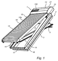
- the screening assembly is generally designated 1 and comprises a screening device in the form of a roller shutter 10 and at least one appliance member 100.
- the appliance member or appliance members, of which one appliance member 100 is shown in Fig. 1 are releasably connected to a top element 12 of the roller shutter 10.
- the roller shutter 10 has two side rails 13 and 14 extending at right angles to the top element 12, two mounting rails 15 and 16 extending in parallel with and below a respective side rail 13, 14, and a transverse element 17 extending between the ends of the mounting rails 15 and 16 opposite the ends at the top element 12.
- a shutter body 18 includes a plurality of slats 18a providing the screening, and the ends of the slats 18a are guided in the side rails 13 and 14.
- the invention is applicable to screening assemblies comprising screening devices having similar configuration to the shown and described roller shutter, and is applicable to other types of screening devices in the same category as the roller shutter, i.e. exterior screening devices positioned on top of for instance a roof window and having a screening body to be rolled out from the top element as well, such as for instance an awning blind.
- the roller shutter 10 is intended to be mounted on the exterior of a window 2, for instance a roof window adapted for installation in an inclined roof.
- the window comprises in a manner known per se a frame 3 and a sash 4 encasing a pane 5.
- the sash 4 will most often be openable relative to the frame, viz. hinge connected to the frame 3, as in the embodiment shown, for instance by means of a set of pivot hinges (not shown) positioned close to a central axis of the window to allow the sash 3 to pivot relative to the frame 2, or by a more traditional hinge positioned at the top of the window.
- the roller shutter may be mounted on the window frame or on sash.
- the roller shutter 10 is mounted on the frame 3 in that the mounting rails 15 and 16 are fastened to a respective side piece of the frame 3.
- the side rails 13 and 14 are connected to the sash 4 such that the side rails 13 and 14, and consequently the shutter body 18 and slats 18a, follow the tilting movement of the sash 4.
- the aperture to be screened is defined by the area limited by the top element 12, the side rails 13, 14, and the bottom of the window, that is the bottom piece of the frame or sash of the window. This aperture thus corresponds in substance to the pane.
- the shutter body 18 is adapted to be moved from a non-screening position to a screening position, in which it covers the pane and other parts of the window to a larger or lesser degree.
- the shutter body 18 is adapted to be wound up in and rolled out from the top element 12 by means of a driving device, not shown, in a direction perpendicular to said longitudinal direction to a screening position.
- the top element 12 is adapted to be positioned at the top of the window in the mounted position, i.e. at the top piece of the frame and the sash of the window, and comprises in the embodiment shown a top cover 21 and two outer end covers, of which the right-hand end cover 22 is visible in Fig. 1 .
- the top element 12 defines a longitudinal direction in parallel with the top piece of the frame and sash of the window. Hence, this longitudinal direction is parallel to the longitudinal direction of the slats and perpendicular to the direction, in which the shutter body moves when rolling up and out the shutter body.
- a track 23 is provided in the top element 12.
- the track 23 is a continuous track having a substantially dovetail-shaped cross-sectional configuration as will be described in further detail below.
- the track 23 is, in the embodiment shown, provided in the top cover 21.
- the appliance members 100 and 120 are positioned in the track 23 by introducing them from one of the ends of the top cover 21 of the top element 12.
- Terms such as “left-hand” and “right-hand” refer to the orientation shown in for instance Fig. 1 and are utilized for reasons of convenience only.
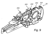
- the top cover 21 is at each of its longitudinal ends connected to an end element 20, cf. Fig. 9 , which in the position of use of the screening assembly 1 is covered by the end cover 22.
- the end element 20 is to that end provided with a plurality of abutment surfaces of which three abutment surfaces 201, 202 and 205 are indicated in Fig. 9 .
- the track 23 of the top element 12, which in the embodiment shown is provided in the top cover 21, is received in the space provided substantially between abutment surfaces 202 and 205. In this area, there is a further abutment surface 203 on which an upstanding pin 204 is formed.
- the pin 204 cooperates (in a manner not shown) with a corresponding aperture (not shown) in the top cover 21.
- Other configurations of the top element 12 are of course conceivable; for instance, the top element could be designed as moulded element including all of cover parts, or manufactured in another manner, just as the track in the top element could be formed in any suitable manner.
- the screening assembly 1 comprises the roller shutter 10 with its top element 12 defining a longitudinal direction x-x, and at least one appliance member, in the embodiment shown one appliance member 100.
- the appliance member 100 is releasably connected with the top element 12 of the roller shutter in any suitable manner, examples of which will be described below.
- the top cover 21 of the top element 12 includes an external track 23 extending in the longitudinal direction x-x on the outer side of the top cover 21.
- the track 23 is adapted to receive each appliance member and provides first engagement means for the releasable connection with the appliance member 100 and other appliance members.
- the track is positioned externally, the interior parts of the roller shutter are at no time exposed during the above-mentioned operations, and the interior parts thus remain protected by the top cover, which thus provides a substantially unaffected surface. Notwithstanding the need to protect and hide the interior parts, slight or non-substantial openings may be provided in the track.
- An upper surface 21a of the top cover 21 of the top element 12 of the roller shutter 10 is slightly curved with a predefined radius of curvature. Alternatively, the upper surface may be substantially plane, thus giving the top cover a more L-shaped profile.
- the top cover 21 may be formed in any suitable manner but in the embodiment shown, the top cover is shaped in a roll-forming operation.
- the first engagement means for the releasable connection with the appliance member 100 are in the embodiment shown in Fig. 3 provided in the form of the shape of the track 23.
- the track 23 has a bottom portion 24 positioned at a lower level, i.e. at a level displayed inwards in the direction towards the interior of the top element 12, than the upper surface 21a of the top cover 21 of the top element 12 of the roller shutter 10. From the bottom portion 24, the track 23 is narrowed at each longitudinal side edge and ends in two opposite projecting portions 25 and 26, such that the distance between the opposite projecting portions 25 and 26 is smaller than the width of the bottom portion 24 in a direction perpendicular to the longitudinal direction of the track 24. In this manner, a joint slightly resembling a dovetail joint is formed, having abutment surface portions 27 and 28, respectively, formed below the opposite projecting portions 25 and 26.
- the second engagement means are provided by giving the appliance member a shape complementary to the first engagement means of the top element top cover of the roller shutter.
- this could for instance be provided by any of the versions of the appliance members shown in Figs 10 to 14 .
- an appliance member 110 in the form of a rain sensor is shown.
- the appliance member 110 On each longitudinal side 110a and 110b, the appliance member 110 has second engagement means 111, 112 for cooperation with the first engagement means of the track 23.
- the second engagement means on the one longitudinal side 110a is in the form of one or more, here three, protruding flaps 111 which, in the mounted position abut either of the abutment surface portions 27, 28, depending on the orientation of the rain sensor 110 in the track 23.
- the second engagement means take the form of two curved strips 112 having a slight resilient or springy action.
- the strips 112 act in two manners: One in positive engagement with the other of the abutment surface portions 28, 27 of the track 23, and one resilient contact with the wall portion of the track 23 between the bottom portion 24 and the abutment surface portion 28. That is, by means of the strips 112, retention of the rain sensor 110 in the track 23 is increased.
- the presence of the springy strips 112 makes it furthermore possible to mount the rain sensor 110 in the track 23 in two manners: Either by inserting the rain sensor 110 into the track 23 in the longitudinal direction from one end thereof, or by positioning the longitudinal side 110 with its protruding flaps 111 below one of the opposite projecting portions 25 or 26, and then pivot the rain sensor 110 while simultaneously pressing the strips 112 inwards towards the longitudinal side 110b of the rain sensor 110 until the strips 112 are positioned below the other of the opposite projecting portions 26 or 25, following which the strips 112 automatically resume their relaxed condition shown in Fig. 11 .
- the upper surface 113a of the rain sensor 110 may be substantially plane or have a curvature corresponding to that of the upper surface 21a of the top cover 21 of the top element 12 of the roller shutter 10.
- the rain sensor 110 is kept in the track 23 partly by the mutually cooperation of the engagement means as described in the above, but is also held in non-positive engagement with the wall portions of the track by the friction between the engagement means 111, 112 and the wall portions.
- FIG. 12 the appliance member 100 shown in Figs 1 and 2 is shown.
- This appliance member is a solar cell panel 100 and is provided as a unit comprising a casing 101 and the actual solar cell panel elements 101.
- the casing 101 has second engagement means corresponding to those of the rain sensor 110 shown in Figs 10 and 11 , of shich a number of flaps 103 are shown.
- the upper surface 101a of the casing 101 may be flat or plane, or have a curvature resembling that of the upper surface 21a of the top cover 21 of the top element 12 of the roller shutter 10, whereas the upper surface of the solar cell panel elements 102 may be plane.
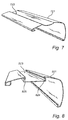
- the appliance member is a filling panel 120 having a profiling with an upper surface 121a having a curvature similar to that of the upper surface 21a of the top cover 21 of the top element 12 of the roller shutter 10.
- Longitudinally extending flanges 122, 123 protrude from depending wall portions 124, 125 of the filling panel 120, the flanges 122, 123 forming the second engagement means cooperating with the abutment surface portions 27 and 28 of the track 23.
- Fig. 14 shows an example of a mounted position of the filling panel 120 in the track 23. This position is representative of all appliance members positioned in the track of the top element in the embodiments in which the upper surface of each appliance member is flush with the upper surface of the top element of the roller shutter. As described, the term "flush" is to be interpreted within the defined context as allowing for slight variations in the respective levels of the top element and the appliance member, as long as a viewer does not conceive any conspicuous difference.
- releasable connection between the top element and the at least one appliance member other than the shown external track
- the releasable connection may be provided by a set of protruding and/or upstanding flaps or flanges on either the top element or the appliance member or members to engage releasably with a corresponding accommodating aperture or slit on the other of the appliance member(s) and top element.
- the track 823 of the top cover 821 may be provided with an electrically conducting coating and/or separate strips 824 and 825 as indicated.
- the coating or separate strips are positioned as shown, namely on surfaces of the track facing downwards. Any moisture that might intrude below the appliance member or members mounted in the track is thus not able to reach the coating or separate strips, or at least it is rendered more difficult for moisture getting into contact with the coating or separate strips.
- the appliance member or members would in that case be provided with corresponding electrical wiring.
- Other forms of electrical conductors are conceivable as well, for instance conductors extending transversely to the track of the top element.
- the appliance member or members would then be provided with for instance carbon contacts to cooperate with the conductor of the top element.
- appliance members are solar cell panels, photovoltaic elements, members providing lighting, such as LCD and OLED, filling panels, screening devices, members adapted for carrying information, sign boards, name plates, advertising signs, and sensor elements.
- coatings or strips that are adhesive may also be utilized in the track.
- adhesive may for instance be ethylene vinyl acetate (EVA) due to its low-temperature toughness, stress-crack resistance, hot-melt adhesive water proof properties, resistance to UV radiation, and heat-conducting properties.
- EVA ethylene vinyl acetate
- the latter property is particularly advantageous in connection with the use of solar cell panels or other heat-generating appliance members, as the generated heat may then easily be transferred to other parts of the top element and the roller shutter as such to prevent local overheating.
- the screening assembly may be provided in a well-defined delivery state in which the appliance member is a filling panel extending substantially throughout the length of the top cover of the roller shutter top element.
- the screening assembly may, for instance as shown in Fig. 2 , be provided in a delivery state in which one appliance member is a solar cell panel 100 and another appliance member is a filling panel 120.
- a delivery state in which one appliance member is a solar cell panel 100 and another appliance member is a filling panel 120.
- This meets the most common demand for appliance members in screening assemblies comprising an electrically operated roller shutter.
- Solar cell panels renders the wiring much less complicated than roller shutters operated by motors supplied by power from for instance the interior of the building, and also meet the increasing requirements to use of sustainable energy sources.
- Such solar cell panels may be used for supplying power to various units, one of which is the above-mentioned direct supply of an electrically operated roller shutter.
- Appliance members such as a further solar cell panel may be connected to the track of the roller shutter as well, for instance for supplying power to a chargeable battery located within the top element of the roller shutter and acting as a back-up power supply to the electrically operated roller shutter during extended periods of overcast or rainy weather.
- kit of appliance members for use with a screening assembly in any of the above-mentioned two delivery states. This is particularly the case if it is desirable to upgrade a manually operated roller shutter to an electrically operated roller shutter.
- the kit may comprise a solar cell panel (or an additional solar cell panel, as the case may be) and a rain sensor.
- the filling panel 120 is provided with a number of weakening lines 126 and 127, perpendicular to the longitudinal direction x-x at distances corresponding to a predefined size of the appliance member or members.
- weakening lines extending along the edges of the filling panel parallel to the longitudinal direction are conceivable as well.
Claims (18)
- Volet roulant (10) présentant un élément supérieur (12) définissant une longueur et une direction longitudinale, deux rails latéraux (13, 14) s'étendant à angle droit par rapport à l'élément supérieur (12), et d'un corps de volet (18) comprenant une pluralité de lames (18a) réalisant l'écran, des extrémités des lames (18a) étant guidées dans les rails latéraux (13, 14), ledit élément supérieur (12) étant adapté pour être raccordé à au moins un élément d'appareil (100, 110 ; 120), caractérisé en ce que ledit élément supérieur comprend une gorge externe (23 ; 423 ; 523 ; 623 ; 723 ; 823) s'étendant dans la direction longitudinale sur le côté externe dudit élément supérieur, ladite gorge étant adaptée pour recevoir chacun dudit au moins un élément d'appareil, en ce que ladite gorge (23) a une portion de dessous (24) positionnée à un niveau vers l'intérieur dans la direction vers l'intérieur de l'élément supérieur (12) par rapport à une surface supérieure (21a) de l'élément supérieur (12), et en ce que ladite gorge est adaptée pour recevoir chacun dudit au moins un élément d'appareil par un raccordement amovible.
- Volet roulant (10) selon la revendication 1, dans lequel ledit élément supérieur (12) comprend un recouvrement supérieur (21 ; 421 ; 521 ; 621 ; 721 ; 821), et dans lequel ladite gorge externe (23 ; 423 ; 523 ; 623 ; 723 ; 823) est formée dans le recouvrement supérieur.
- Volet roulant selon la revendication 1 ou 2, dans lequel la gorge présente une extension qui est inférieure à la longueur de l'élément supérieur (12) et/ou est composée d'un certain nombre de parties de gorge situées à une distance mutuelle les unes des autres dans la direction longitudinale de l'élément supérieur.
- Volet roulant selon la revendication 2, dans lequel la gorge (23 ; 423 ; 523 ; 623 ; 723 ; 823) dans le recouvrement supérieur (21 ; 421 ; 521 ; 621 ; 721 ; 821) de l'élément supérieur (12) est fournie en formant le recouvrement supérieur dans une opération de formage aux galets.
- Volet roulant selon l'une quelconque des revendications précédentes, dans lequel la section transversale de la gorge est choisie dans le groupe constitué d'une forme en U, d'une forme en V, d'une forme rectangulaire, carrée, en queue d'aronde, d'une forme principale rectangulaire ou carrée avec une ou plusieurs rainures dans les côtés.
- Volet roulant selon l'une quelconque des revendications précédentes, dans lequel la gorge est pourvue d'un revêtement et/ou de bandes séparées, ledit revêtement et/ou lesdites bandes étant de préférence électriquement conducteurs ou adhésifs.
- Ensemble de protection (1) comprenant un volet roulant (10) selon l'une quelconque des revendications 1 à 6, et au moins un élément d'appareil (100, 110 ; 120), caractérisé en ce que l'élément supérieur comprend une gorge externe (23 ; 423 ; 523 ; 623 ; 723 ; 823) s'étendant dans la direction longitudinale sur le côté externe dudit élément supérieur, en ce que ladite gorge (23) présente une portion de dessous (24) positionnée à un niveau vers l'intérieur dans la direction vers l'intérieur de l'élément supérieur (12) par rapport à une surface supérieure de l'élément supérieur (12), et en ce que chacun dudit au moins un élément d'appareil est reçu dans ladite gorge par un raccordement amovible.
- Ensemble de protection selon la revendication 7, dans lequel ladite gorge fournit des premiers moyens d'enclenchement pour le raccordement amovible avec le au moins un élément d'appareil, et ledit au moins un élément d'appareil est pourvu de seconds moyens d'enclenchement qui sont complémentaires des premiers moyens d'enclenchement de l'élément supérieur du volet roulant.
- Ensemble de protection selon la revendication 8, dans lequel lesdits premiers et seconds moyens d'enclenchement sont adaptés pour fournir un raccordement amovible au moyen d'un enclenchement positif entre le volet roulant et le au moins un élément d'appareil, de préférence en ce que les premiers et seconds moyens d'enclenchement comprennent des parties de coopération mutuelle d'un assemblage à queue d'aronde ou d'un assemblage à rainure et languette.
- Ensemble de protection selon la revendication 8, dans lequel lesdits premiers et seconds moyens d'enclenchement sont adaptés pour fournir un raccordement amovible au moyen d'un enclenchement non positif.
- Ensemble de protection selon l'une quelconque des revendications 7 à 10, dans lequel des moyens de blocage supplémentaires sont prévus.
- Ensemble de protection selon l'une quelconque des revendications 7 à 11, dans lequel le raccordement amovible entre l'élément supérieur et le au moins un élément d'appareil comprend un ensemble de pattes ou brides faisant saillie et/ou droites soit sur l'élément supérieur soit sur l'élément ou les éléments d'appareil pour s'enclencher de façon amovible avec une ouverture ou fente d'accueil correspondante sur l'autre du (des) élément(s) d'appareil et l'élément supérieure, de préférence la (les) patte(s) ou la (les) bride(s) droite (s) et/ou faisant saillie est/sont fournie (s) dans la gorge externe elle-même.
- Ensemble de protection selon l'une des revendications 7 à 12, dans lequel le au moins un élément d'appareil est choisi dans le groupe comprenant des panneaux de cellule solaire, des éléments photovoltaïques, des organes fournissant un éclairage tels qu'un LCD ou une DELO, des panneaux de remplissage, des organes adaptés pour porter des informations, des enseignes, des plaques signalétiques, des enseignes publicitaires, et des éléments de capteur.
- Ensemble de protection selon l'une quelconque des revendications 7 à 13, dans lequel l'ensemble de protection est fourni dans un état de livraison dans lequel l'élément d'appareil est un panneau de remplissage s'étendant sensiblement sur toute la longueur du recouvrement supérieur de l'élément supérieur du volet roulant, ou l'élément d'appareil est un panneau de cellule solaire et un autre élément d'appareil est un panneau de remplissage.
- Ensemble de protection selon la revendication 14, dans lequel le panneau de remplissage est pourvu d'un certain nombre de lignes de moindre résistance, de préférence une ligne de moindre résistance s'étendant le long des bords du panneau de remplissage parallèle à la direction longitudinale, et/ou de préférence perpendiculaire à la direction longitudinale à des distances correspondant à une taille prédéfinie de l'élément ou des éléments d'appareil.
- Ensemble de protection selon l'une des revendications 7 à 15, dans lequel la surface supérieure de chacun dudit au moins un élément d'appareil affleure sensiblement avec la surface supérieure de l'élément supérieur du volet roulant.
- Procédé de fabrication d'un ensemble de protection comprenant un volet roulant et au moins un élément d'appareil, comprenant les étapes de :fourniture d'un élément supérieur,formation d'une gorge externe dans la direction longitudinale sur le côté externe dudit élément supérieur, avec une portion de dessous positionnée à un niveau vers l'intérieur dans la direction vers l'intérieur de l'élément supérieur par rapport à une surface supérieure de l'élément supérieur,fourniture de deux rails latéraux et raccordement des rails latéraux à l'élément supérieur,fourniture d'un corps de volet comprenant une pluralité de lames et insertion d'extrémités des lames dans les rails latéraux,fourniture d'au moins un élément d'appareil,raccordement amovible du au moins un élément d'appareil avec ladite gorge de sorte que ledit élément d'appareil soit sensiblement contenu dans ladite gorge.
- Procédé selon la revendication 17, dans lequel l'étape de fourniture de l'élément supérieur comprend les étapes de fourniture d'un recouvrement supérieur avec ladite gorge et de fourniture de deux recouvrements d'extrémité pour un raccordement au recouvrement d'extrémité, et dans lequel l'étape de raccordement amovible du au moins un élément d'appareil est de préférence réalisée au moins en partie avant l'étape de raccordement d'au moins l'un des recouvrements d'extrémité avec le recouvrement supérieur.
Applications Claiming Priority (1)
| Application Number | Priority Date | Filing Date | Title |
|---|---|---|---|
| DK2010050119 | 2010-05-31 |
Publications (2)
| Publication Number | Publication Date |
|---|---|
| EP2390455A1 EP2390455A1 (fr) | 2011-11-30 |
| EP2390455B1 true EP2390455B1 (fr) | 2016-05-11 |
Family
ID=43661964
Family Applications (1)
| Application Number | Title | Priority Date | Filing Date |
|---|---|---|---|
| EP11168149.0A Active EP2390455B1 (fr) | 2010-05-31 | 2011-05-31 | Volet roulant doté d'un élément supérieur adapté pour recevoir un ou plusieurs éléments d'appareils, ensemble d'écran comprenant un tel volet roulant et un ou plusieurs éléments d'appareils et procédé de fabrication d'un tel ensemble d'écran |
Country Status (4)
| Country | Link |
|---|---|
| EP (1) | EP2390455B1 (fr) |
| ES (1) | ES2583760T3 (fr) |
| HU (1) | HUE029088T2 (fr) |
| PL (1) | PL2390455T3 (fr) |
Families Citing this family (11)
| Publication number | Priority date | Publication date | Assignee | Title |
|---|---|---|---|---|
| DE102012017000B4 (de) * | 2012-08-28 | 2015-10-29 | Bernhard Spindler | Lichteinlassende Beschattungseinrichtung für Dachfenster |
| CN106285432B (zh) * | 2016-10-18 | 2018-03-09 | 绍兴红葡萄纺织装饰品有限公司 | 一种带有智能感光功能的升降窗帘 |
| EP3959410A1 (fr) | 2019-11-25 | 2022-03-02 | VKR Holding A/S | Agencement d'écran doté d'un dispositif de protection |
| WO2021104594A1 (fr) | 2019-11-25 | 2021-06-03 | Vkr Holding A/S | Agencement de criblage externe doté d'un élément de rappel à réglage automatique |
| WO2021104592A1 (fr) | 2019-11-25 | 2021-06-03 | Vkr Holding A/S | Agencement de criblage externe comportant un ensemble de lamelles |
| ES2953157T3 (es) | 2019-11-25 | 2023-11-08 | Vkr Holding As | Disposición de pantalla externa con cubiertas laterales |
| DE102022118669A1 (de) | 2021-07-29 | 2023-02-02 | Vkr Holding A/S | Abschirmungsanordnung mit einer verbesserten Spannvorrichtung |
| DE202021104709U1 (de) | 2021-09-01 | 2021-12-01 | Vkr Holding A/S | Externe Abschirmungsanordnung für eine mehrere Fenstereinheiten umfassende Dachfensteranordnung |
| DE202021104710U1 (de) | 2021-09-01 | 2021-12-01 | Vkr Holding A/S | Externe Abschirmungsanordnung mit einer verbesserten Beschlaganordnung für eine mehrere Fenstereinheiten umfassende Dachfensteranordnung |
| DE202021104711U1 (de) | 2021-09-01 | 2021-12-01 | Vkr Holding A/S | Externe Abschirmungsanordnung mit Lichtdichtheitsmitteln für eine mehrere Fenstereinheiten umfassende Dachfensteranordnung |
| PL439591A1 (pl) * | 2021-11-22 | 2023-05-29 | Fakro Pp Spółka Z Ograniczoną Odpowiedzialnością | Ruchoma zasłona elementu budowlanego |
Family Cites Families (7)
| Publication number | Priority date | Publication date | Assignee | Title |
|---|---|---|---|---|
| AU572242B2 (en) * | 1984-01-10 | 1988-05-05 | Mocco Helga Maria Wollert | Frame assembly |
| DE19914677B4 (de) | 1999-03-31 | 2006-07-06 | Becker-Antriebe Gmbh | Solarbetriebener Rolladen |
| FR2800794B1 (fr) * | 1999-11-05 | 2003-07-04 | Rehau Sa | Caisson de volet roulant avec profile de suspension integre pour rideau ou autre piece ou structure d'occultation interieure |
| FR2842860B1 (fr) | 2002-07-26 | 2007-02-16 | Unaferm Sa Soc | Bloc d'alimentation pour volets roulants et similaires a commande motorisee |
| FR2894278B1 (fr) | 2005-12-05 | 2010-12-24 | Unaferm Sa Soc | Volet roulant motorise comportant une alimentation electrique integree |
| CN102046910A (zh) | 2008-05-28 | 2011-05-04 | Vkr控股公司 | 具有可倾斜板条的卷帘 |
| CN102046911A (zh) | 2008-05-28 | 2011-05-04 | Vkr控股公司 | 具有驱动装置和呈齿形带形式的驱动元件的卷帘 |
-
2011
- 2011-05-31 PL PL11168149.0T patent/PL2390455T3/pl unknown
- 2011-05-31 HU HUE11168149A patent/HUE029088T2/en unknown
- 2011-05-31 EP EP11168149.0A patent/EP2390455B1/fr active Active
- 2011-05-31 ES ES11168149.0T patent/ES2583760T3/es active Active
Also Published As
| Publication number | Publication date |
|---|---|
| HUE029088T2 (en) | 2017-02-28 |
| ES2583760T3 (es) | 2016-09-22 |
| EP2390455A1 (fr) | 2011-11-30 |
| PL2390455T3 (pl) | 2016-12-30 |
Similar Documents
| Publication | Publication Date | Title |
|---|---|---|
| EP2390455B1 (fr) | Volet roulant doté d'un élément supérieur adapté pour recevoir un ou plusieurs éléments d'appareils, ensemble d'écran comprenant un tel volet roulant et un ou plusieurs éléments d'appareils et procédé de fabrication d'un tel ensemble d'écran | |
| JP4216221B2 (ja) | 瓦一体型太陽電池モジュール | |
| EP2597245B1 (fr) | Éléments d'appareil pour fenêtre comprenant un écran | |
| US8943769B2 (en) | Pane module for use in a window | |
| US11489483B2 (en) | Solar window construction and methods | |
| JP2008007934A (ja) | 太陽発電型ブラインド、およびそれを利用した太陽光発電方法 | |
| EP2142723B1 (fr) | Fenêtre de toit | |
| CN103362255B (zh) | 一种太阳能单坡智能天窗 | |
| PL224719B1 (pl) | Zestaw konstrukcji przenikających przez dach z obróbką blacharską | |
| EP2472029B1 (fr) | Procédé pour le montage d'un raccord d'étanchéité pour fenêtre de toite et système d'étanchéité pour fenêtre de toite | |
| JP6130371B2 (ja) | 改良された位置決めおよび固定特徴を持つ光起電力装置、および組立方法 | |
| JP4090195B2 (ja) | カーポート,テラス等の屋外構築物 | |
| US20070256373A1 (en) | Insulated window panels | |
| CN105178778B (zh) | 一种复合式门框 | |
| US10812012B2 (en) | Hinging inverted seam module mounting system | |
| DE102012104528A1 (de) | Profilsystem zur Befestigung von flexiblen Paneels | |
| KR101644139B1 (ko) | 자동 및 수동 개폐가 가능한 지붕 구조물 | |
| KR101320644B1 (ko) | 측벽용 갤러리 창호를 갖는 지붕 구조물 | |
| US11264939B2 (en) | Exterior siding material with integrated solar panel | |
| US20210152118A1 (en) | Window mounted photovoltaic system with brackets | |
| EP3779089A1 (fr) | Cadre de lucarne installé dans ou sur un toit d'un bâtiment, système comprenant une lucarne et procédé de fixation d'un cadre de lucarne | |
| EP2284328A2 (fr) | Élément de couverture de toit | |
| KR101386123B1 (ko) | 건물 연결패널을 갖는 지붕 구조물 | |
| EP4183967B1 (fr) | Couverture mobile pour un élément de construction | |
| US11984844B2 (en) | Window-mounted interior solar panel |
Legal Events
| Date | Code | Title | Description |
|---|---|---|---|
| AK | Designated contracting states |
Kind code of ref document: A1 Designated state(s): AL AT BE BG CH CY CZ DE DK EE ES FI FR GB GR HR HU IE IS IT LI LT LU LV MC MK MT NL NO PL PT RO RS SE SI SK SM TR |
|
| AX | Request for extension of the european patent |
Extension state: BA ME |
|
| PUAI | Public reference made under article 153(3) epc to a published international application that has entered the european phase |
Free format text: ORIGINAL CODE: 0009012 |
|
| 17P | Request for examination filed |
Effective date: 20120316 |
|
| GRAP | Despatch of communication of intention to grant a patent |
Free format text: ORIGINAL CODE: EPIDOSNIGR1 |
|
| INTG | Intention to grant announced |
Effective date: 20151211 |
|
| RIC1 | Information provided on ipc code assigned before grant |
Ipc: E06B 9/17 20060101ALI20151130BHEP Ipc: E06B 9/00 20060101AFI20151130BHEP |
|
| GRAS | Grant fee paid |
Free format text: ORIGINAL CODE: EPIDOSNIGR3 |
|
| GRAA | (expected) grant |
Free format text: ORIGINAL CODE: 0009210 |
|
| AK | Designated contracting states |
Kind code of ref document: B1 Designated state(s): AL AT BE BG CH CY CZ DE DK EE ES FI FR GB GR HR HU IE IS IT LI LT LU LV MC MK MT NL NO PL PT RO RS SE SI SK SM TR |
|
| REG | Reference to a national code |
Ref country code: GB Ref legal event code: FG4D |
|
| REG | Reference to a national code |
Ref country code: CH Ref legal event code: EP |
|
| REG | Reference to a national code |
Ref country code: AT Ref legal event code: REF Ref document number: 798834 Country of ref document: AT Kind code of ref document: T Effective date: 20160515 |
|
| REG | Reference to a national code |
Ref country code: FR Ref legal event code: PLFP Year of fee payment: 6 |
|
| REG | Reference to a national code |
Ref country code: IE Ref legal event code: FG4D |
|
| REG | Reference to a national code |
Ref country code: DE Ref legal event code: R096 Ref document number: 602011026338 Country of ref document: DE |
|
| REG | Reference to a national code |
Ref country code: NL Ref legal event code: FP |
|
| REG | Reference to a national code |
Ref country code: LT Ref legal event code: MG4D |
|
| REG | Reference to a national code |
Ref country code: ES Ref legal event code: FG2A Ref document number: 2583760 Country of ref document: ES Kind code of ref document: T3 Effective date: 20160922 |
|
| PG25 | Lapsed in a contracting state [announced via postgrant information from national office to epo] |
Ref country code: LT Free format text: LAPSE BECAUSE OF FAILURE TO SUBMIT A TRANSLATION OF THE DESCRIPTION OR TO PAY THE FEE WITHIN THE PRESCRIBED TIME-LIMIT Effective date: 20160511 Ref country code: FI Free format text: LAPSE BECAUSE OF FAILURE TO SUBMIT A TRANSLATION OF THE DESCRIPTION OR TO PAY THE FEE WITHIN THE PRESCRIBED TIME-LIMIT Effective date: 20160511 Ref country code: NO Free format text: LAPSE BECAUSE OF FAILURE TO SUBMIT A TRANSLATION OF THE DESCRIPTION OR TO PAY THE FEE WITHIN THE PRESCRIBED TIME-LIMIT Effective date: 20160811 |
|
| PG25 | Lapsed in a contracting state [announced via postgrant information from national office to epo] |
Ref country code: HR Free format text: LAPSE BECAUSE OF FAILURE TO SUBMIT A TRANSLATION OF THE DESCRIPTION OR TO PAY THE FEE WITHIN THE PRESCRIBED TIME-LIMIT Effective date: 20160511 Ref country code: SE Free format text: LAPSE BECAUSE OF FAILURE TO SUBMIT A TRANSLATION OF THE DESCRIPTION OR TO PAY THE FEE WITHIN THE PRESCRIBED TIME-LIMIT Effective date: 20160511 Ref country code: RS Free format text: LAPSE BECAUSE OF FAILURE TO SUBMIT A TRANSLATION OF THE DESCRIPTION OR TO PAY THE FEE WITHIN THE PRESCRIBED TIME-LIMIT Effective date: 20160511 Ref country code: LV Free format text: LAPSE BECAUSE OF FAILURE TO SUBMIT A TRANSLATION OF THE DESCRIPTION OR TO PAY THE FEE WITHIN THE PRESCRIBED TIME-LIMIT Effective date: 20160511 Ref country code: PT Free format text: LAPSE BECAUSE OF FAILURE TO SUBMIT A TRANSLATION OF THE DESCRIPTION OR TO PAY THE FEE WITHIN THE PRESCRIBED TIME-LIMIT Effective date: 20160912 Ref country code: GR Free format text: LAPSE BECAUSE OF FAILURE TO SUBMIT A TRANSLATION OF THE DESCRIPTION OR TO PAY THE FEE WITHIN THE PRESCRIBED TIME-LIMIT Effective date: 20160812 |
|
| PG25 | Lapsed in a contracting state [announced via postgrant information from national office to epo] |
Ref country code: IT Free format text: LAPSE BECAUSE OF FAILURE TO SUBMIT A TRANSLATION OF THE DESCRIPTION OR TO PAY THE FEE WITHIN THE PRESCRIBED TIME-LIMIT Effective date: 20160511 |
|
| REG | Reference to a national code |
Ref country code: CH Ref legal event code: PL |
|
| PG25 | Lapsed in a contracting state [announced via postgrant information from national office to epo] |
Ref country code: LI Free format text: LAPSE BECAUSE OF NON-PAYMENT OF DUE FEES Effective date: 20160531 Ref country code: EE Free format text: LAPSE BECAUSE OF FAILURE TO SUBMIT A TRANSLATION OF THE DESCRIPTION OR TO PAY THE FEE WITHIN THE PRESCRIBED TIME-LIMIT Effective date: 20160511 Ref country code: RO Free format text: LAPSE BECAUSE OF FAILURE TO SUBMIT A TRANSLATION OF THE DESCRIPTION OR TO PAY THE FEE WITHIN THE PRESCRIBED TIME-LIMIT Effective date: 20160511 Ref country code: CH Free format text: LAPSE BECAUSE OF NON-PAYMENT OF DUE FEES Effective date: 20160531 Ref country code: DK Free format text: LAPSE BECAUSE OF FAILURE TO SUBMIT A TRANSLATION OF THE DESCRIPTION OR TO PAY THE FEE WITHIN THE PRESCRIBED TIME-LIMIT Effective date: 20160511 Ref country code: SK Free format text: LAPSE BECAUSE OF FAILURE TO SUBMIT A TRANSLATION OF THE DESCRIPTION OR TO PAY THE FEE WITHIN THE PRESCRIBED TIME-LIMIT Effective date: 20160511 |
|
| REG | Reference to a national code |
Ref country code: DE Ref legal event code: R097 Ref document number: 602011026338 Country of ref document: DE |
|
| REG | Reference to a national code |
Ref country code: IE Ref legal event code: MM4A |
|
| PG25 | Lapsed in a contracting state [announced via postgrant information from national office to epo] |
Ref country code: SM Free format text: LAPSE BECAUSE OF FAILURE TO SUBMIT A TRANSLATION OF THE DESCRIPTION OR TO PAY THE FEE WITHIN THE PRESCRIBED TIME-LIMIT Effective date: 20160511 |
|
| REG | Reference to a national code |
Ref country code: HU Ref legal event code: AG4A Ref document number: E029088 Country of ref document: HU |
|
| PLBE | No opposition filed within time limit |
Free format text: ORIGINAL CODE: 0009261 |
|
| STAA | Information on the status of an ep patent application or granted ep patent |
Free format text: STATUS: NO OPPOSITION FILED WITHIN TIME LIMIT |
|
| PG25 | Lapsed in a contracting state [announced via postgrant information from national office to epo] |
Ref country code: MC Free format text: LAPSE BECAUSE OF FAILURE TO SUBMIT A TRANSLATION OF THE DESCRIPTION OR TO PAY THE FEE WITHIN THE PRESCRIBED TIME-LIMIT Effective date: 20160511 |
|
| 26N | No opposition filed |
Effective date: 20170214 |
|
| REG | Reference to a national code |
Ref country code: FR Ref legal event code: PLFP Year of fee payment: 7 |
|
| PG25 | Lapsed in a contracting state [announced via postgrant information from national office to epo] |
Ref country code: SI Free format text: LAPSE BECAUSE OF FAILURE TO SUBMIT A TRANSLATION OF THE DESCRIPTION OR TO PAY THE FEE WITHIN THE PRESCRIBED TIME-LIMIT Effective date: 20160511 Ref country code: IE Free format text: LAPSE BECAUSE OF NON-PAYMENT OF DUE FEES Effective date: 20160531 |
|
| REG | Reference to a national code |
Ref country code: FR Ref legal event code: PLFP Year of fee payment: 8 |
|
| PG25 | Lapsed in a contracting state [announced via postgrant information from national office to epo] |
Ref country code: CY Free format text: LAPSE BECAUSE OF FAILURE TO SUBMIT A TRANSLATION OF THE DESCRIPTION OR TO PAY THE FEE WITHIN THE PRESCRIBED TIME-LIMIT Effective date: 20160511 |
|
| PG25 | Lapsed in a contracting state [announced via postgrant information from national office to epo] |
Ref country code: IS Free format text: LAPSE BECAUSE OF FAILURE TO SUBMIT A TRANSLATION OF THE DESCRIPTION OR TO PAY THE FEE WITHIN THE PRESCRIBED TIME-LIMIT Effective date: 20160511 Ref country code: LU Free format text: LAPSE BECAUSE OF NON-PAYMENT OF DUE FEES Effective date: 20160531 Ref country code: MT Free format text: LAPSE BECAUSE OF NON-PAYMENT OF DUE FEES Effective date: 20160531 Ref country code: TR Free format text: LAPSE BECAUSE OF FAILURE TO SUBMIT A TRANSLATION OF THE DESCRIPTION OR TO PAY THE FEE WITHIN THE PRESCRIBED TIME-LIMIT Effective date: 20160511 Ref country code: MK Free format text: LAPSE BECAUSE OF FAILURE TO SUBMIT A TRANSLATION OF THE DESCRIPTION OR TO PAY THE FEE WITHIN THE PRESCRIBED TIME-LIMIT Effective date: 20160511 |
|
| PG25 | Lapsed in a contracting state [announced via postgrant information from national office to epo] |
Ref country code: BG Free format text: LAPSE BECAUSE OF FAILURE TO SUBMIT A TRANSLATION OF THE DESCRIPTION OR TO PAY THE FEE WITHIN THE PRESCRIBED TIME-LIMIT Effective date: 20160511 |
|
| PG25 | Lapsed in a contracting state [announced via postgrant information from national office to epo] |
Ref country code: AL Free format text: LAPSE BECAUSE OF FAILURE TO SUBMIT A TRANSLATION OF THE DESCRIPTION OR TO PAY THE FEE WITHIN THE PRESCRIBED TIME-LIMIT Effective date: 20160511 |
|
| REG | Reference to a national code |
Ref country code: AT Ref legal event code: UEP Ref document number: 798834 Country of ref document: AT Kind code of ref document: T Effective date: 20160511 |
|
| PGFP | Annual fee paid to national office [announced via postgrant information from national office to epo] |
Ref country code: NL Payment date: 20230417 Year of fee payment: 13 |
|
| P01 | Opt-out of the competence of the unified patent court (upc) registered |
Effective date: 20230526 |
|
| PGFP | Annual fee paid to national office [announced via postgrant information from national office to epo] |
Ref country code: FR Payment date: 20230421 Year of fee payment: 13 Ref country code: ES Payment date: 20230602 Year of fee payment: 13 Ref country code: DE Payment date: 20230404 Year of fee payment: 13 Ref country code: CZ Payment date: 20230428 Year of fee payment: 13 |
|
| PGFP | Annual fee paid to national office [announced via postgrant information from national office to epo] |
Ref country code: PL Payment date: 20230417 Year of fee payment: 13 Ref country code: HU Payment date: 20230419 Year of fee payment: 13 Ref country code: AT Payment date: 20230425 Year of fee payment: 13 |
|
| PGFP | Annual fee paid to national office [announced via postgrant information from national office to epo] |
Ref country code: BE Payment date: 20230418 Year of fee payment: 13 |
|
| PGFP | Annual fee paid to national office [announced via postgrant information from national office to epo] |
Ref country code: GB Payment date: 20230406 Year of fee payment: 13 |