EP2390430A2 - Befestigungsvorrichtung, insbesondere für wandhängende Sanitärobjekte - Google Patents
Befestigungsvorrichtung, insbesondere für wandhängende Sanitärobjekte Download PDFInfo
- Publication number
- EP2390430A2 EP2390430A2 EP11401503A EP11401503A EP2390430A2 EP 2390430 A2 EP2390430 A2 EP 2390430A2 EP 11401503 A EP11401503 A EP 11401503A EP 11401503 A EP11401503 A EP 11401503A EP 2390430 A2 EP2390430 A2 EP 2390430A2
- Authority
- EP
- European Patent Office
- Prior art keywords
- screw
- base body
- fastening device
- carriage
- internal thread
- Prior art date
- Legal status (The legal status is an assumption and is not a legal conclusion. Google has not performed a legal analysis and makes no representation as to the accuracy of the status listed.)
- Granted
Links
- 238000005452 bending Methods 0.000 description 11
- 239000000919 ceramic Substances 0.000 description 4
- 238000010276 construction Methods 0.000 description 3
- 229910000831 Steel Inorganic materials 0.000 description 2
- 239000010959 steel Substances 0.000 description 2
- 230000003750 conditioning effect Effects 0.000 description 1
- 230000000694 effects Effects 0.000 description 1
- 230000002349 favourable effect Effects 0.000 description 1
- 238000009434 installation Methods 0.000 description 1
- 238000004519 manufacturing process Methods 0.000 description 1
- 239000002184 metal Substances 0.000 description 1
- 230000003014 reinforcing effect Effects 0.000 description 1
Images
Classifications
-
- E—FIXED CONSTRUCTIONS
- E03—WATER SUPPLY; SEWERAGE
- E03D—WATER-CLOSETS OR URINALS WITH FLUSHING DEVICES; FLUSHING VALVES THEREFOR
- E03D11/00—Other component parts of water-closets, e.g. noise-reducing means in the flushing system, flushing pipes mounted in the bowl, seals for the bowl outlet, devices preventing overflow of the bowl contents; devices forming a water seal in the bowl after flushing, devices eliminating obstructions in the bowl outlet or preventing backflow of water and excrements from the waterpipe
- E03D11/13—Parts or details of bowls; Special adaptations of pipe joints or couplings for use with bowls, e.g. provisions in bowl construction preventing backflow of waste-water from the bowl in the flushing pipe or cistern, provisions for a secondary flushing, for noise-reducing
- E03D11/14—Means for connecting the bowl to the wall, e.g. to a wall outlet
-
- E—FIXED CONSTRUCTIONS
- E03—WATER SUPPLY; SEWERAGE
- E03C—DOMESTIC PLUMBING INSTALLATIONS FOR FRESH WATER OR WASTE WATER; SINKS
- E03C1/00—Domestic plumbing installations for fresh water or waste water; Sinks
- E03C1/12—Plumbing installations for waste water; Basins or fountains connected thereto; Sinks
- E03C1/32—Holders or supports for basins
- E03C1/322—Holders or supports for basins connected to the wall only
-
- F—MECHANICAL ENGINEERING; LIGHTING; HEATING; WEAPONS; BLASTING
- F16—ENGINEERING ELEMENTS AND UNITS; GENERAL MEASURES FOR PRODUCING AND MAINTAINING EFFECTIVE FUNCTIONING OF MACHINES OR INSTALLATIONS; THERMAL INSULATION IN GENERAL
- F16B—DEVICES FOR FASTENING OR SECURING CONSTRUCTIONAL ELEMENTS OR MACHINE PARTS TOGETHER, e.g. NAILS, BOLTS, CIRCLIPS, CLAMPS, CLIPS OR WEDGES; JOINTS OR JOINTING
- F16B2/00—Friction-grip releasable fastenings
- F16B2/02—Clamps, i.e. with gripping action effected by positive means other than the inherent resistance to deformation of the material of the fastening
- F16B2/14—Clamps, i.e. with gripping action effected by positive means other than the inherent resistance to deformation of the material of the fastening using wedges
Definitions
- the invention relates to a fastening device, in particular for wall-hung sanitary objects having the features of the preamble of claim 1.
- WO 2009/074301 is a fastening device for a sanitary object, in particular a toilet bowl, known.
- the known fastening device has a hook-shaped body, which comes with a contact surface on a wall to the plant and can be fastened to the wall.
- On a bearing surface perpendicular to the wall the sanitary object can be supported.
- the sanitary object is held by means of a screw which extends through a receiving opening of the sanitary object and into the basic body.
- a carriage On the main body, a carriage is guided linearly with a nut, wherein the guide is arranged obliquely to the contact surface. The screw engages in the nut. By tightening the nut of the carriage is moved along its guide and thereby generates a force that pulls the sanitary object both to the main body and the wall.
- the invention is based on the object to increase the rigidity with smaller overall dimensions.
- the fastening device has a base body which has a contact surface for abutment against a wall.
- the main body serves to fasten an object, in particular a sanitary object such as a toilet bowl.
- the fastening device has a carriage, which is guided obliquely to the contact surface.
- the guide need not be linear, but it may for example also be arcuate, which has an effect on the resulting from the tightening torque fastening forces in the direction and size.
- the carriage has an internal thread element, which is in particular rotationally fixedly connected to the carriage.
- the female thread member may also be integral with the carriage.
- a female thread is preformed, but a section may be provided, in which during the assembly of the object on a wall first the internal thread is formed.
- a bore can be provided with inwardly standing longitudinal ribs.
- the fastening device has a screw for passage through a receiving opening of the object, which can be screwed into the internal thread element.
- the ratio of the length L to the nominal diameter D of the internal thread element is at least 1, in particular at least 1.5.
- the length L refers to the length of the internal thread.
- the internal thread element itself if it is ever more than one piece with the carriage, can actually be longer.
- the female thread element is significantly longer. This allows the guide of the carriage is relatively steep to the contact surface. A steeper guide causes on the one hand, that the body can be made more compact, but on the other hand, that the force acting on the screw bending moment increases very strong when tightening the screw.
- a long internal thread element can derive high bending moments, so that overall a more compact construction with high rigidity is achieved.
- the screw and the female thread member according to the invention could be reversed, that is, the screw would be arranged in the carriage and held with her head in the carriage.
- the shank of the screw would extend into the object and the object with an internally threaded element, in particular a nut, be mounted on the shank of the screw.
- the length L corresponds to the length of the head of the screw.
- the guide of the carriage on the base body at an angle W is less than 55 °, in particular 50 ° or less, is arranged to the contact surface.
- guide surfaces, which form the guide enclose the angle W at its steepest point with the contact surface.
- at an angle W of 50 ° results in a favorable ratio of the dimensions, the achievable rigidity and the required torque during assembly.
- the invention also proposes that the internal thread element moves as close as possible to the object to be fastened.
- the base body has a bearing surface for an object to be fastened, and the distance A of the internal thread element of this Bearing surface is a maximum of 2.0 times, in particular a maximum of 1.5 times, the nominal diameter D of the female thread member. Since the screw can be supported in this area only difficult against the bending moment, this feature leads to a high rigidity and stability can be achieved even with slender screws.
- the fastening arrangement has a guide surface for the carriage, which extends to a bearing surface of the base body for the object to be fastened. This ensures that the carriage and thus also the internal thread element moves close to the object to be fastened, which on the one hand enables a compact construction and on the other hand low bending moments in the screw. Accordingly, it is not important that the guide surface extends just up to the support surface, but it is sufficient if it extends at least up to the vicinity.
- the screw is not radially supported directly on the object, especially if this is made of sensitive ceramic, but the screw has a sleeve for radial abutment in the receiving opening of the object. This will prevent damage to the object.
- the sleeve Since in the region of the sleeve at least partially the bending moment of the screw can be transferred to the object, the sleeve has a length h which corresponds to at least 0.7 times the nominal diameter D of the female thread element.
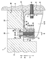
- the single figure shows a sectional view of a fastening device 1 according to the invention for fastening an object 2, here a toilet bowl made of ceramic, on a wall 3.
- the fastening device 1 has an angular base body 4 made of plastic, the first leg 5 outside a contact surface 6 for conditioning forms on the wall 3.
- a mounting hole 7 is arranged, through which a threaded rod 8 grouted in the wall 3 protrudes.
- the base body 4 is tensioned with the contact surface 6 against the wall 3.
- a second leg 10 of the main body 4 forms a support for the object 2.
- the upper side of the second leg 10 serves as a bearing surface 11 on which the object comes to rest with an upper inner wall 12.
- At the top of the drawing corresponds in the embodiment also above, that is, it is in the representation of a vertical section. However, it could just as well be a horizontal cut or the embodiment could be upside down.
- the angle-shaped basic body 4 has, inter alia, reinforcing side walls 13.
- the side walls 13 are perpendicular to both legs 5, 10, wherein only one of the side walls 13 is shown, while the other side wall 13 is arranged symmetrically in front of the cutting plane.
- a guide surface 14 is arranged on the side wall 13, which is inclined at an angle W of approximately 50 ° to the wall 3 or the contact surface 6.
- the guide surfaces 14 form a guide 15 of an arranged between the side walls 13, approximately cuboid carriage 16 made of plastic, which has a corresponding contour (not shown).
- cylindrical internal thread member 17 is disposed of metal with an internal thread 18 having through hole 19 and a central constriction 20 on the outside. In the manufacture of the carriage 16, the internal thread member 17 is molded as an insert and therefore finds optimal support.
- the object has a fastening portion 21 which projects up to the wall 3 and is supported on the support surface 11.
- the attachment portion 21 is penetrated by a receiving opening 22.
- the receiving opening 22 tapers step-like manner relative to the main body 4, thereby forming a shoulder 23 against which the head 24 of a screw 25 made of steel is supported.
- the screw 25 is inserted in the mounting of the object 2 on the wall 3 after placing the object 2 on the base body 4 in the receiving opening 22. It protrudes through the receiving opening 22 through into the base body 4 and is screwed into the female thread member 17.
- the support on the shoulder 23 is not direct, since the contact of steel on ceramic could lead to cracks in the ceramic.
- the head 24 is therefore supported by a washer 26 and a hat-shaped sleeve 27 on the shoulder 23 from. At the same time, the sleeve 27 also prevents direct radial contact of the screw 25 in the receiving opening 22.
- the guide 15 extends as described at an angle W of about 50 ° to the abutment surface 6 and the guide surfaces 14 extend to the support surface 11 of the base body 4.
- the carriage 16 Inserted from below into the base body 4 and held by a snap connection (not shown) on the guide 15.
- the guide 15 is bounded on both sides by stops 28, so that the carriage can not slide out of the guide 15 during assembly.
- the sleeve 27 does not need to be as long as the female threaded member 17.
- Their length h is approximately 1.25 times the nominal diameter D of the screw 25 or of the internal thread element 17.
Abstract
Description
- Die Erfindung betrifft eine Befestigungsvorrichtung, insbesondere für wandhängende Sanitärobjekte mit den Merkmalen des Oberbegriffs des Anspruchs 1.
- Aus der Druckschrift
WO 2009/074301 ist eine Befestigungsvorrichtung für ein Sanitärobjekt, im Speziellen ein Toilettenbecken, bekannt. Die bekannte Befestigungsvorrichtung weist einen hakenförmigen Grundkörper auf, der mit einer Anlagefläche an einer Wand zur Anlage kommt und an der Wand befestigbar ist. Auf einer senkrecht zur Wand stehenden Auflagerfläche kann das Sanitärobjekt abgestützt werden. Gehalten wird das Sanitärobjekt mittels einer Schraube, die durch eine Aufnahmeöffnung des Sanitärobjekts hindurch bis in den Grundkörper reicht. Am Grundkörper ist ein Schlitten mit einer Mutter linear geführt, wobei die Führung schräg zur Anlagefläche angeordnet ist. Die Schraube greift in die Mutter. Durch Anziehen der Mutter wird der Schlitten entlang seiner Führung verschoben und hierdurch eine Kraft erzeugt, die das Sanitärobjekt sowohl zum Grundkörper als auch zur Wand zieht. - Der Erfindung liegt die Aufgabe zu Grunde, die Steifigkeit zu erhöhen bei insgesamt kleineren Abmessungen.
- Diese Aufgabe wird erfindungsgemäß durch die Merkmale des Anspruchs 1 gelöst. Die erfindungsgemäße Befestigungsvorrichtung weist einen Grundkörper auf, der eine Anlagefläche zur Anlage an einer Wand aufweist. Der Grundkörper dient der Befestigung eines Objekts, insbesondere eines Sanitärobjekts wie ein Toilettenbecken. Die Befestigungsvorrichtung weist einen Schlitten auf, der schräg zur Anlagefläche geführt ist. Dabei muss die Führung nicht linear sein, sondern sie kann beispielsweise auch bogenförmig sein, was sich auf die aus dem Anzugsmoment resultierenden Befestigungskräfte in Richtung und Größe auswirkt. Der Schlitten weist ein Innengewindeelement auf, das insbesondere drehfest mit dem Schlitten verbunden ist. Das Innengewindeelement kann auch einstückig mit dem Schlitten sein. Vorzugsweise ist ein Innengewinde vorgeformt, es kann jedoch auch ein Abschnitt vorgesehen werden, in dem während der Montage des Objekts an einer Wand erst das Innengewinde geformt wird. Hierzu kann beispielsweise eine Bohrung mit nach innen stehenden Längsrippen vorgesehen werden. Weiterhin weist die Befestigungsvorrichtung eine Schraube zur Durchführung durch eine Aufnahmeöffnung des Objekts auf, die in das Innengewindeelement einschraubbar ist.
- Erfindungsgemäß ist das Verhältnis der Länge L zum Nenndurchmesser D des Innengewindeelements mindestens 1, insbesondere mindestens 1,5. Dabei bezieht sich die Länge L auf die Länge des Innengewindes. Das Innengewindeelement selbst, sofern es überhaupt mehrstückig mit dem Schlitten ist, kann tatsächlich länger sein. Gegenüber dem Stand der Technik, der eine Mutter als Innengewindeelement vorsieht, ist erfindungsgemäß das Innengewindeelement deutlich länger. Dies erlaubt es, dass die Führung des Schlittens relativ steil zur Anlagefläche steht. Eine steilere Führung bewirkt einerseits, dass der Grundkörper kompakter gebaut werden kann, jedoch andererseits, dass das auf die Schraube wirkende Biegemoment beim Anziehen der Schraube sehr starkt ansteigt. Ein langes Innengewindeelement kann hohe Biegemomente ableiten, so dass hierdurch insgesamt ein kompakterer Aufbau bei hoher Steifigkeit erreicht wird.
- Äquivalent könnten erfindungsgemäß die Schraube und das Innengewindeelement vertauscht sein, das heißt die Schraube würde im Schlitten angeordnet und mit ihrem Kopf im Schlitten gehalten werden. Der Schaft der Schraube würde bis in das Objekt reichen und das Objekt mit einem Innengewindeelement, insbesondere einer Mutter, auf dem Schaft der Schraube befestigt werden. In diesem Fall entspricht die Länge L der Länge des Kopfes der Schraube.
- Vorzugsweise ist die Führung des Schlittens am Grundkörper in einem Winkel W kleiner 55°, insbesondere 50° oder weniger, zur Anlagefläche angeordnet ist. Damit ist gemeint, dass Führungsflächen, die die Führung bilden, an ihrer steilsten Stelle mit der Anlagefläche den Winkel W einschließen. Insbesondere bei einem Winkel W von 50° ergibt sich ein günstiges Verhältnis aus den Abmaßen, der erreichbaren Steifigkeit und den erforderlichen Drehmomenten bei der Montage.
- Um insbesondere das Biegemoment in der Schraube möglichst niedrig zu halten, schlägt die Erfindung weiterhin vor, dass das Innengewindeelement möglichst nahe an das zu befestigende Objekt rückt. Vorzugsweise weist der Grundkörper eine Auflagerfläche für ein zu befestigendes Objekt auf, und der Abstand A des Innengewindeelements dieser Auflagerfläche beträgt maximal das 2,0-fache, insbesondere maximal das 1,5-fache, des Nenndurchmessers D des Innengewindeelements. Da die Schraube in diesem Bereich nur schwierig entgegen dem Biegemoment abgestützt werden kann, führt dieses Merkmal dazu, dass selbst mit schlanken Schrauben eine hohe Steifigkeit und Stabiliät erreicht werden kann.
- In einer bevorzugten Ausführung weist die erfindungsgemäße Befestigungsanordnung eine Führungsfläche für den Schlitten auf, die bis zu einer Auflagerfläche des Grundkörpers für das zu befestigende Objekt reicht. Hierdurch wird erreicht, dass der Schlitten und somit auch das Innengewindeelement nahe an das zu befestigende Objekt rückt, was einerseits einen kompakten Aufbau und andererseits niedrige Biegemomente in der Schraube ermöglicht. Entsprechend kommt es nicht darauf an, dass die Führungsfläche genau bis zu zur Auflagerfläche reicht, sondern es genügt, wenn sie zumindest bis in die Nähe reicht.
- Vorzugsweise stützt sich die Schraube radial nicht direkt an dem Objekt ab, insbesondere wenn dieses aus empflindlicher Keramik gefertigt ist, sondern die Schraube weist eine Hülse zur radialen Anlage in der Aufnahmeöffnung des Objekts auf. Hierdurch werden Schäden am Objekt vermieden.
- Da im Bereich der Hülse zumindest teilweise das Biegemoment der Schraube auf das Objekt übertragen werden kann, weist die Hülse eine Länge h auf, die mindestens dem 0,7-fachen des Nenndurchmessers D des Innengewindeelements entspricht.
- Die Erfindung wird nachfolgend anhand eines Ausführungsbeispiels erläutert.
- Die einzige Figur zeigt in einer Schnittdarstellung eine erfindungsgemäße Befestigungsvorrichtung 1 zur Befestigung eines Objekts 2, hier eines Toilettenbeckens aus Keramik, an einer Wand 3. Die Befestigungsvorrichtung 1 weist einen winkelförmigen Grundkörper 4 aus Kunststoff auf, dessen erster Schenkel 5 außen eine Anlagefläche 6 zur Anlage an der Wand 3 bildet. Im ersten Schenkel 5 ist ein Befestigungsloch 7 angeordnet, durch den eine in der Wand 3 eingemörtelte Gewindestange 8 ragt. Mittels einer Mutter 9 ist der Grundkörper 4 mit der Anlagefläche 6 gegen die Wand 3 gespannt. Ein zweiter Schenkel 10 des Grundkörpers 4 bildet eine Stütze für das Objekt 2. Die obere Seite des zweiten Schenkels 10 dient als Auflagerfläche 11, auf der das Objekt mit einer oberen Innenwand 12 zur Anlage kommt. Oben in der Zeichnung entspricht im Ausführungsbeispiel auch oben, das heißt es handelt sich bei der Darstellung um einen vertikalen Schnitt. Allerdings könnte es sich ebenso gut um einen horizontalen Schnitt handeln oder das Ausführungsbeispiel könnte auf dem Kopf dargestellt sein.
- Der winkelförmige Grundkörper 4 weist unter anderem zur Verstärkung Seitenwände 13 auf. Die Seitenwände 13 stehen senkrecht zu beiden Schenkeln 5, 10, wobei nur eine der Seitenwände 13 dargestellt ist, während die andere Seitenwand 13 symmetrisch vor der Schnittebene angeordnet ist. Nach innen weisend ist an der Seitenwand 13 je eine Führungsfläche 14 angeordnet, die schräg in einem Winkel W von etwa 50° zur Wand 3 bzw. zur Anlagefläche 6 steht. Die Führungsflächen 14 bilden eine Führung 15 eines zwischen den Seitenwänden 13 angeordneten, in etwa quaderförmigen Schlittens 16 aus Kunststoff, der eine korrespondierende Kontur (nicht dargestellt) aufweist. Im Schlitten 16 ist ein längliches, zylindrisches Innengewindeelement 17 aus Metall mit einem ein Innengewinde 18 aufweisenden Durchgangsloch 19 und einer mittigen Einschnürung 20 an der Außenseite angeordnet. Bei der Herstellung des Schlittens 16 wird das Innengewindeelement 17 als Einlegeteil umspritzt und findet daher optimalen Halt.
- Das Objekt weist einen Befestigungsabschnitt 21 auf, der bis zur Wand 3 ragt und sich auf der Auflagerfläche 11 abstützt. Der Befestigungsabschnitt 21 wird durch eine Aufnahmeöffnung 22 durchsetzt. Die Aufnahmeöffnung 22 verjüngt sich zum Grundkörper 4 hin stufenartig und bildet hierdurch eine Schulter 23, an der sich der Kopf 24 einer Schraube 25 aus Stahl abstützt. Die Schraube 25 wird bei der Montage des Objekts 2 an der Wand 3 nach dem Aufsetzen des Objekts 2 auf dem Grundkörper 4 in die Aufnahmeöffnung 22 gesteckt. Sie ragt durch die Aufnahmeöffnung 22 hindurch bis in den Grundkörper 4 und wird in das Innengewindeelement 17 eingeschraubt. Die Abstützung an der Schulter 23 erfolgt nicht direkt, da der Kontakt von Stahl auf Keramik zu Rissen in der Keramik führen könnte. Der Kopf 24 stützt sich daher über eine Unterlegscheibe 26 und eine hutförmige Hülse 27 auf der Schulter 23 ab. Gleichzeitig verhindert die Hülse 27 auch eine unmittelbare radiale Anlage der Schraube 25 in der Aufnahmeöffnung 22.
- Beim Anziehen der Schraube 25 wird der Schlitten 16 schräg entlang der Führung 15 gezogen. Dies bewirkt ein Heranziehen des Objekts 2 sowohl in Richtung des Grundkörpers 4 als auch in Richtung der Wand 3.
- Um einen kompakten und gleichzeitig steifen sowie stabilen Aufbau zu erreichen, verläuft die Führung 15 wie beschrieben in einem Winkel W von etwa 50° zur Anlagefläche 6 und die Führungsflächen 14 reichen bis zur Auflagerfläche 11 des Grundkörpers 4. Im Rahmen einer Vormontage wird der Schlitten 16 von unten in den Grundkörper 4 eingesetzt und durch eine Schnappverbindung (nicht dargestellt) an der Führung 15 gehalten. Die Führung 15 ist zu beiden Seiten durch Anschläge 28 begrenzt, so dass der Schlitten während der Montage nicht aus der Führung 15 gleiten kann.
- Durch den steilen Winkel W treten erhebliche Biegemomente in der Schraube 25 auf. Damit dieses Biegemoment nicht zu hoch wird, ist der Abstand A zwischen der Innengewindehülse 17 und der Auflagerfläche 11 gering gehalten und durch den unteren Anschlag 28 auf etwa das 1,2-fache des Nenndurchmessers D der Schraube 25 bzw. des Innengewindeelements 17 begrenzt. Somit ist der entsprechende Biegearm, der sich durch die Anlage der Schraube 25 an der Hülse 27 einerseits und am Innengewinde 18 andererseits ergibt, relativ kurz. Damit das Biegemoment auch gut auf das Innengewindeelement 17 und von dort in den Schlitten 16 übertragen werden kann, ist das Innengewindeelement 17 bzw. das Innengewinde 18 relativ lang. Ihre Länge L beträgt etwa das 3-fache des Nenndurchmessers D der Schraube 25 bzw. des Innengewindeelements 17. Im Bereich der Aufnahmeöffnung 22 wird das Biegemoment teilweise axial vom Kopf 24 der Schraube 25 und teilweise radial über die Hülse 27 übertragen. Entsprechend braucht die Hülse 27 nicht so lang wie das Innengewindeelement 17 sein. Ihre Länge h beträgt etwa das 1,25-fache des Nenndurchmessers D der Schraube 25 bzw. des Innengewindeelements 17.
-
- 1
- Befestigungsvorrichtung
- 2
- Objekt
- 3
- Wand
- 4
- Grundkörper
- 5
- erster Schenkel
- 6
- Anlagefläche
- 7
- Befestigungsloch
- 8
- Gewindestange
- 9
- Mutter
- 10
- zweiter Schenkel
- 11
- Auflagerfläche
- 12
- Innenwand
- 13
- Seitenwand
- 14
- Führungsfläche
- 15
- Führung
- 16
- Schlitten
- 17
- Innengewindeelement
- 18
- Innengewinde
- 19
- Durchgangsloch
- 20
- Einschnürung
- 21
- Befestigungsabschnitt
- 22
- Aufnahmeöffnung
- 23
- Schulter
- 24
- Kopf
- 25
- Schraube
- 26
- Unterlegscheibe
- 27
- Hülse
- 28
- Anschlag
- A
- Abstand zwischen der Innengewindehülse 17 und der Auflagerfläche 11
- D
- Nenndurchmessers der Schraube 25 bzw. des Innengewindeelements 17
- h
- Länge der Hülse 27
- L
- Länge des Innengewindeelements 17
- W
- Winkel der Führung 15 zur Anlagefläche 6
Claims (6)
- Befestigungsvorrichtung (1), insbesondere für wandhängende Sanitärobjekte, mit- einem Grundkörper (4), der eine Anlagefläche (6) zur Anlage an einer Wand (3) aufweist, und an dem ein Objekt (2), insbesondere ein Sanitärobjekt, befestigbar ist,- einem Schlitten (16), der am Grundkörper (4) schräg zur Anlagefläche (6) geführt ist und ein Innengewindeelement (17) aufweist, und- einer Schraube (25) zur Durchführung durch eine Aufnahmeöffnung (22) des Objekts (2), die in das Innengewindeelement (17) einschraubbar ist,
dadurch gekennzeichnet, dass das Verhältnis der Länge L zum Nenndurchmesser D des Innengewindeelements (17) mindestes 1, insbesondere mindestens 1,5, ist. - Befestigungsvorrichtung nach Anspruch 1, dadurch gekennzeichnet, dass die Führung (15) des Schlittens (16) am Grundkörper (4) in einem Winkel W kleiner 55°, insbesondere 50° oder weniger, zur Anlagefläche (6) angeordnet ist.
- Befestigungsvorrichtung nach Anspruch 1 oder 2, dadurch gekennzeichnet, dass der Grundkörper (4) eine Auflagerfläche (11) für ein zu befestigendes Objekt (2) aufweist, und dass der Abstand A des Innengewindeelements (17) zur Auflagerfläche (11) maximal das 2,0-fache, insbesondere maximal das 1,5-fache, des Nenndurchmessers D des Innengewindeelements (17) beträgt.
- Befestigungsvorrichtung nach einem der Ansprüche 1 bis 3, dadurch gekennzeichnet, dass der Schlitten (16) entlang einer oder mehrerer Führungsflächen (14) am Grundkörper (4) geführt ist und dass mindestens eine der Führungsflächen (14) im Wesentlichen bis zu einer Auflagerfläche (11) des Grundkörpers (4) für ein zu befestigendes Objekt (2) reicht.
- Befestigungsvorrichtung nach einem der Ansprüche 1 bis 4, dadurch gekennzeichnet, dass die Schraube (25) eine Hülse (27) zur radialen Anlage in der Aufnahmeöffnung (22) des Objekts (2) aufweist.
- Befestigungsvorrichtung nach Anspruch 5, dadurch gekennzeichnet, dass die Länge h der Hülse (27) mindestens dem 0,7-fachen des Nenndurchmessers D des Innengewindeelements (17) entspricht.
Priority Applications (1)
| Application Number | Priority Date | Filing Date | Title |
|---|---|---|---|
| PL11401503T PL2390430T3 (pl) | 2010-05-25 | 2011-05-03 | Mechanizm mocujący, w szczególności do wiszących na ścianie obiektów sanitarnych |
Applications Claiming Priority (1)
| Application Number | Priority Date | Filing Date | Title |
|---|---|---|---|
| DE102010021429A DE102010021429A1 (de) | 2010-05-25 | 2010-05-25 | Befestigungsvorrichtung, insbesondere für wandhängende Sanitärobjekte |
Publications (3)
| Publication Number | Publication Date |
|---|---|
| EP2390430A2 true EP2390430A2 (de) | 2011-11-30 |
| EP2390430A3 EP2390430A3 (de) | 2015-09-30 |
| EP2390430B1 EP2390430B1 (de) | 2016-12-07 |
Family
ID=44246096
Family Applications (1)
| Application Number | Title | Priority Date | Filing Date |
|---|---|---|---|
| EP11401503.5A Active EP2390430B1 (de) | 2010-05-25 | 2011-05-03 | Befestigungsvorrichtung, insbesondere für wandhängende Sanitärobjekte |
Country Status (4)
| Country | Link |
|---|---|
| EP (1) | EP2390430B1 (de) |
| DE (1) | DE102010021429A1 (de) |
| ES (1) | ES2616409T3 (de) |
| PL (1) | PL2390430T3 (de) |
Cited By (5)
| Publication number | Priority date | Publication date | Assignee | Title |
|---|---|---|---|---|
| EP2657417A1 (de) * | 2012-04-27 | 2013-10-30 | fischerwerke GmbH & Co. KG | Befestigungsvorrichtung für Sanitärkeramiken und Befestigungsanordnung |
| EP3093405A3 (de) * | 2015-05-11 | 2017-03-01 | Kamil Ridvan Erbil | Vorrichtung zur montage einer wandmontierten toilettenschüssel |
| CN107002400A (zh) * | 2014-09-17 | 2017-08-01 | 费希尔厂有限责任两合公司 | 用于固定卫浴物品的固定装置 |
| EP2669530A3 (de) * | 2012-06-01 | 2017-08-16 | Mihaly Pataki | Verankerungsanordnung zum Befestigen von Elementen aneinander |
| EP3276096A1 (de) * | 2016-07-29 | 2018-01-31 | Ece Banyo Gerecleri Sanayi ve Ticaret Anonim Sirketi | Für aufgehängte wasserklosetts entwickelte montagevorrichtung |
Families Citing this family (2)
| Publication number | Priority date | Publication date | Assignee | Title |
|---|---|---|---|---|
| DE102015120525B4 (de) * | 2015-11-26 | 2017-08-10 | Villeroy & Boch Ag | Befestigungssystem für einen Toilettensitz, Käfig, Käfigmutter, Verwendung, Anordnung und Verfahren |
| DE102022124822A1 (de) * | 2022-09-27 | 2024-03-28 | Villeroy & Boch Aktiengesellschaft | Befestigungsvorrichtung, Set zum Befestigen und Montageverfahren |
Citations (1)
| Publication number | Priority date | Publication date | Assignee | Title |
|---|---|---|---|---|
| WO2009074301A1 (de) | 2007-12-12 | 2009-06-18 | Villeroy & Boch Ag | Vorrichtung zum befestigen eines wandhängenden objektes |
Family Cites Families (4)
| Publication number | Priority date | Publication date | Assignee | Title |
|---|---|---|---|---|
| SE360898B (de) * | 1971-11-05 | 1973-10-08 | Ifoe Ab | |
| NL9401071A (nl) * | 1994-06-28 | 1996-02-01 | Koninkl Sphinx Nv | Montagesamenstel voor een wandclosetpot. |
| ITPD20070400A1 (it) * | 2007-12-04 | 2009-06-05 | Fischer Italia S R L Uniperson | Staffa di supporto particolarmente per sanitari sospesi |
| ITPD20070401A1 (it) * | 2007-12-04 | 2009-06-05 | Fischer Italia S R L Uniperson | Dispositivo di fissaggio, particolarmente per sanitari sospesi a parete |
-
2010
- 2010-05-25 DE DE102010021429A patent/DE102010021429A1/de not_active Withdrawn
-
2011
- 2011-05-03 ES ES11401503.5T patent/ES2616409T3/es active Active
- 2011-05-03 PL PL11401503T patent/PL2390430T3/pl unknown
- 2011-05-03 EP EP11401503.5A patent/EP2390430B1/de active Active
Patent Citations (1)
| Publication number | Priority date | Publication date | Assignee | Title |
|---|---|---|---|---|
| WO2009074301A1 (de) | 2007-12-12 | 2009-06-18 | Villeroy & Boch Ag | Vorrichtung zum befestigen eines wandhängenden objektes |
Cited By (6)
| Publication number | Priority date | Publication date | Assignee | Title |
|---|---|---|---|---|
| EP2657417A1 (de) * | 2012-04-27 | 2013-10-30 | fischerwerke GmbH & Co. KG | Befestigungsvorrichtung für Sanitärkeramiken und Befestigungsanordnung |
| EP2669530A3 (de) * | 2012-06-01 | 2017-08-16 | Mihaly Pataki | Verankerungsanordnung zum Befestigen von Elementen aneinander |
| CN107002400A (zh) * | 2014-09-17 | 2017-08-01 | 费希尔厂有限责任两合公司 | 用于固定卫浴物品的固定装置 |
| CN107002400B (zh) * | 2014-09-17 | 2019-04-23 | 费希尔厂有限责任两合公司 | 用于固定卫浴物品的固定装置 |
| EP3093405A3 (de) * | 2015-05-11 | 2017-03-01 | Kamil Ridvan Erbil | Vorrichtung zur montage einer wandmontierten toilettenschüssel |
| EP3276096A1 (de) * | 2016-07-29 | 2018-01-31 | Ece Banyo Gerecleri Sanayi ve Ticaret Anonim Sirketi | Für aufgehängte wasserklosetts entwickelte montagevorrichtung |
Also Published As
| Publication number | Publication date |
|---|---|
| EP2390430B1 (de) | 2016-12-07 |
| PL2390430T3 (pl) | 2017-06-30 |
| EP2390430A3 (de) | 2015-09-30 |
| ES2616409T3 (es) | 2017-06-13 |
| DE102010021429A1 (de) | 2011-12-01 |
Similar Documents
| Publication | Publication Date | Title |
|---|---|---|
| EP2390430B1 (de) | Befestigungsvorrichtung, insbesondere für wandhängende Sanitärobjekte | |
| EP2382395B1 (de) | Vorrichtung zum ausrichten eines körpers relativ zu einer unterlage- oder anlagefläche | |
| EP3155274B1 (de) | Hochfeste befestigungsvorrichtung | |
| EP3586018B1 (de) | Befestigungsvorrichtung und befestigungsbaugruppe | |
| EP3066347A1 (de) | Spreizanker mit furchen im spreizkonus | |
| EP3418590A1 (de) | Kippdübel | |
| DE102005056578A1 (de) | Befestigung einer Abschleppöse | |
| EP1215404B1 (de) | Befestigungsvorrichtung für ein an einer Platte zu befestigendes Bauteil | |
| EP1780854A1 (de) | Kabel- oder Schlauchverschraubung | |
| DE60107712T2 (de) | Abreissbefestigungselement | |
| DE19946890C2 (de) | Halteelement zur unverlierbaren Halterung von Kopfschrauben | |
| EP3221598B1 (de) | Verformbarer körper sowie system umfassend einen verformbaren körper und einen anti-kriech-ring | |
| EP2390429B1 (de) | Befestigungsvorrichtung insbesondere für wandhängende Sanitärobjekte | |
| DE3006480A1 (de) | Duebel mit wegkontrollierter zwangsweiser spreizung | |
| EP2865903A1 (de) | Spreizanker mit Federelement | |
| DE102008063582A1 (de) | Rohrschelle | |
| EP3394368A1 (de) | Kraftfahrzeugschloss mit drehfallenabstützung | |
| WO2020126935A1 (de) | Elektrischer anschluss | |
| DE3620573A1 (de) | Vorrichtung zum befestigen eines gegenstandes an einer wand oder dgl. | |
| EP3093508B1 (de) | Kippdübel und verfahren zur befestigung mit einem kippdübel | |
| DE202009016484U1 (de) | Hülsenanker zur Anordnung in einem Betonteil | |
| EP2373851B1 (de) | An einer arbeitsplatte über einen adapter befestigte sanitärarmatur | |
| EP2096223B1 (de) | Vorrichtung zum lage- und winkelgenauen Positionieren und Verankern eines Spannstabes | |
| EP3037682A1 (de) | Befestigungselement zur befestigung von anbauteilen an gedämmten gebäudewänden | |
| DE102006025268A1 (de) | Spreizanker |
Legal Events
| Date | Code | Title | Description |
|---|---|---|---|
| AK | Designated contracting states |
Kind code of ref document: A2 Designated state(s): AL AT BE BG CH CY CZ DE DK EE ES FI FR GB GR HR HU IE IS IT LI LT LU LV MC MK MT NL NO PL PT RO RS SE SI SK SM TR |
|
| AX | Request for extension of the european patent |
Extension state: BA ME |
|
| PUAI | Public reference made under article 153(3) epc to a published international application that has entered the european phase |
Free format text: ORIGINAL CODE: 0009012 |
|
| RAP1 | Party data changed (applicant data changed or rights of an application transferred) |
Owner name: FISCHERWERKE GMBH & CO. KG |
|
| PUAL | Search report despatched |
Free format text: ORIGINAL CODE: 0009013 |
|
| AK | Designated contracting states |
Kind code of ref document: A3 Designated state(s): AL AT BE BG CH CY CZ DE DK EE ES FI FR GB GR HR HU IE IS IT LI LT LU LV MC MK MT NL NO PL PT RO RS SE SI SK SM TR |
|
| AX | Request for extension of the european patent |
Extension state: BA ME |
|
| RIC1 | Information provided on ipc code assigned before grant |
Ipc: E03D 11/14 20060101AFI20150826BHEP Ipc: F16B 2/14 20060101ALI20150826BHEP Ipc: E03C 1/322 20060101ALI20150826BHEP |
|
| 17P | Request for examination filed |
Effective date: 20160311 |
|
| RBV | Designated contracting states (corrected) |
Designated state(s): AL AT BE BG CH CY CZ DE DK EE ES FI FR GB GR HR HU IE IS IT LI LT LU LV MC MK MT NL NO PL PT RO RS SE SI SK SM TR |
|
| GRAP | Despatch of communication of intention to grant a patent |
Free format text: ORIGINAL CODE: EPIDOSNIGR1 |
|
| RIC1 | Information provided on ipc code assigned before grant |
Ipc: F16B 2/14 20060101ALI20160804BHEP Ipc: E03D 11/14 20060101AFI20160804BHEP Ipc: E03C 1/322 20060101ALI20160804BHEP |
|
| INTG | Intention to grant announced |
Effective date: 20160901 |
|
| GRAS | Grant fee paid |
Free format text: ORIGINAL CODE: EPIDOSNIGR3 |
|
| GRAA | (expected) grant |
Free format text: ORIGINAL CODE: 0009210 |
|
| AK | Designated contracting states |
Kind code of ref document: B1 Designated state(s): AL AT BE BG CH CY CZ DE DK EE ES FI FR GB GR HR HU IE IS IT LI LT LU LV MC MK MT NL NO PL PT RO RS SE SI SK SM TR |
|
| REG | Reference to a national code |
Ref country code: GB Ref legal event code: FG4D Free format text: NOT ENGLISH |
|
| REG | Reference to a national code |
Ref country code: CH Ref legal event code: EP Ref country code: AT Ref legal event code: REF Ref document number: 851851 Country of ref document: AT Kind code of ref document: T Effective date: 20161215 |
|
| REG | Reference to a national code |
Ref country code: IE Ref legal event code: FG4D Free format text: LANGUAGE OF EP DOCUMENT: GERMAN |
|
| REG | Reference to a national code |
Ref country code: DE Ref legal event code: R096 Ref document number: 502011011279 Country of ref document: DE |
|
| PG25 | Lapsed in a contracting state [announced via postgrant information from national office to epo] |
Ref country code: LV Free format text: LAPSE BECAUSE OF FAILURE TO SUBMIT A TRANSLATION OF THE DESCRIPTION OR TO PAY THE FEE WITHIN THE PRESCRIBED TIME-LIMIT Effective date: 20161207 |
|
| REG | Reference to a national code |
Ref country code: LT Ref legal event code: MG4D |
|
| REG | Reference to a national code |
Ref country code: NL Ref legal event code: MP Effective date: 20161207 |
|
| PG25 | Lapsed in a contracting state [announced via postgrant information from national office to epo] |
Ref country code: SE Free format text: LAPSE BECAUSE OF FAILURE TO SUBMIT A TRANSLATION OF THE DESCRIPTION OR TO PAY THE FEE WITHIN THE PRESCRIBED TIME-LIMIT Effective date: 20161207 Ref country code: LT Free format text: LAPSE BECAUSE OF FAILURE TO SUBMIT A TRANSLATION OF THE DESCRIPTION OR TO PAY THE FEE WITHIN THE PRESCRIBED TIME-LIMIT Effective date: 20161207 Ref country code: NO Free format text: LAPSE BECAUSE OF FAILURE TO SUBMIT A TRANSLATION OF THE DESCRIPTION OR TO PAY THE FEE WITHIN THE PRESCRIBED TIME-LIMIT Effective date: 20170307 Ref country code: GR Free format text: LAPSE BECAUSE OF FAILURE TO SUBMIT A TRANSLATION OF THE DESCRIPTION OR TO PAY THE FEE WITHIN THE PRESCRIBED TIME-LIMIT Effective date: 20170308 |
|
| REG | Reference to a national code |
Ref country code: FR Ref legal event code: PLFP Year of fee payment: 7 |
|
| PG25 | Lapsed in a contracting state [announced via postgrant information from national office to epo] |
Ref country code: RS Free format text: LAPSE BECAUSE OF FAILURE TO SUBMIT A TRANSLATION OF THE DESCRIPTION OR TO PAY THE FEE WITHIN THE PRESCRIBED TIME-LIMIT Effective date: 20161207 Ref country code: HR Free format text: LAPSE BECAUSE OF FAILURE TO SUBMIT A TRANSLATION OF THE DESCRIPTION OR TO PAY THE FEE WITHIN THE PRESCRIBED TIME-LIMIT Effective date: 20161207 Ref country code: FI Free format text: LAPSE BECAUSE OF FAILURE TO SUBMIT A TRANSLATION OF THE DESCRIPTION OR TO PAY THE FEE WITHIN THE PRESCRIBED TIME-LIMIT Effective date: 20161207 |
|
| REG | Reference to a national code |
Ref country code: ES Ref legal event code: FG2A Ref document number: 2616409 Country of ref document: ES Kind code of ref document: T3 Effective date: 20170613 |
|
| PG25 | Lapsed in a contracting state [announced via postgrant information from national office to epo] |
Ref country code: NL Free format text: LAPSE BECAUSE OF FAILURE TO SUBMIT A TRANSLATION OF THE DESCRIPTION OR TO PAY THE FEE WITHIN THE PRESCRIBED TIME-LIMIT Effective date: 20161207 |
|
| PG25 | Lapsed in a contracting state [announced via postgrant information from national office to epo] |
Ref country code: IS Free format text: LAPSE BECAUSE OF FAILURE TO SUBMIT A TRANSLATION OF THE DESCRIPTION OR TO PAY THE FEE WITHIN THE PRESCRIBED TIME-LIMIT Effective date: 20170407 Ref country code: EE Free format text: LAPSE BECAUSE OF FAILURE TO SUBMIT A TRANSLATION OF THE DESCRIPTION OR TO PAY THE FEE WITHIN THE PRESCRIBED TIME-LIMIT Effective date: 20161207 Ref country code: RO Free format text: LAPSE BECAUSE OF FAILURE TO SUBMIT A TRANSLATION OF THE DESCRIPTION OR TO PAY THE FEE WITHIN THE PRESCRIBED TIME-LIMIT Effective date: 20161207 Ref country code: SK Free format text: LAPSE BECAUSE OF FAILURE TO SUBMIT A TRANSLATION OF THE DESCRIPTION OR TO PAY THE FEE WITHIN THE PRESCRIBED TIME-LIMIT Effective date: 20161207 |
|
| PG25 | Lapsed in a contracting state [announced via postgrant information from national office to epo] |
Ref country code: SM Free format text: LAPSE BECAUSE OF FAILURE TO SUBMIT A TRANSLATION OF THE DESCRIPTION OR TO PAY THE FEE WITHIN THE PRESCRIBED TIME-LIMIT Effective date: 20161207 Ref country code: BG Free format text: LAPSE BECAUSE OF FAILURE TO SUBMIT A TRANSLATION OF THE DESCRIPTION OR TO PAY THE FEE WITHIN THE PRESCRIBED TIME-LIMIT Effective date: 20170307 Ref country code: PT Free format text: LAPSE BECAUSE OF FAILURE TO SUBMIT A TRANSLATION OF THE DESCRIPTION OR TO PAY THE FEE WITHIN THE PRESCRIBED TIME-LIMIT Effective date: 20170407 Ref country code: LU Free format text: LAPSE BECAUSE OF NON-PAYMENT OF DUE FEES Effective date: 20170531 |
|
| REG | Reference to a national code |
Ref country code: DE Ref legal event code: R097 Ref document number: 502011011279 Country of ref document: DE |
|
| PLBE | No opposition filed within time limit |
Free format text: ORIGINAL CODE: 0009261 |
|
| STAA | Information on the status of an ep patent application or granted ep patent |
Free format text: STATUS: NO OPPOSITION FILED WITHIN TIME LIMIT |
|
| 26N | No opposition filed |
Effective date: 20170908 |
|
| PG25 | Lapsed in a contracting state [announced via postgrant information from national office to epo] |
Ref country code: SI Free format text: LAPSE BECAUSE OF FAILURE TO SUBMIT A TRANSLATION OF THE DESCRIPTION OR TO PAY THE FEE WITHIN THE PRESCRIBED TIME-LIMIT Effective date: 20161207 Ref country code: DK Free format text: LAPSE BECAUSE OF FAILURE TO SUBMIT A TRANSLATION OF THE DESCRIPTION OR TO PAY THE FEE WITHIN THE PRESCRIBED TIME-LIMIT Effective date: 20161207 |
|
| REG | Reference to a national code |
Ref country code: CH Ref legal event code: PL |
|
| GBPC | Gb: european patent ceased through non-payment of renewal fee |
Effective date: 20170503 |
|
| PG25 | Lapsed in a contracting state [announced via postgrant information from national office to epo] |
Ref country code: MC Free format text: LAPSE BECAUSE OF FAILURE TO SUBMIT A TRANSLATION OF THE DESCRIPTION OR TO PAY THE FEE WITHIN THE PRESCRIBED TIME-LIMIT Effective date: 20161207 |
|
| REG | Reference to a national code |
Ref country code: IE Ref legal event code: MM4A |
|
| PG25 | Lapsed in a contracting state [announced via postgrant information from national office to epo] |
Ref country code: CH Free format text: LAPSE BECAUSE OF NON-PAYMENT OF DUE FEES Effective date: 20170531 Ref country code: LI Free format text: LAPSE BECAUSE OF NON-PAYMENT OF DUE FEES Effective date: 20170531 |
|
| PG25 | Lapsed in a contracting state [announced via postgrant information from national office to epo] |
Ref country code: LU Free format text: LAPSE BECAUSE OF NON-PAYMENT OF DUE FEES Effective date: 20170503 |
|
| REG | Reference to a national code |
Ref country code: BE Ref legal event code: MM Effective date: 20170531 |
|
| PG25 | Lapsed in a contracting state [announced via postgrant information from national office to epo] |
Ref country code: GB Free format text: LAPSE BECAUSE OF NON-PAYMENT OF DUE FEES Effective date: 20170503 Ref country code: IE Free format text: LAPSE BECAUSE OF NON-PAYMENT OF DUE FEES Effective date: 20170503 |
|
| REG | Reference to a national code |
Ref country code: FR Ref legal event code: PLFP Year of fee payment: 8 |
|
| REG | Reference to a national code |
Ref country code: AT Ref legal event code: MM01 Ref document number: 851851 Country of ref document: AT Kind code of ref document: T Effective date: 20170503 |
|
| PG25 | Lapsed in a contracting state [announced via postgrant information from national office to epo] |
Ref country code: AT Free format text: LAPSE BECAUSE OF NON-PAYMENT OF DUE FEES Effective date: 20170503 Ref country code: BE Free format text: LAPSE BECAUSE OF NON-PAYMENT OF DUE FEES Effective date: 20170531 |
|
| PG25 | Lapsed in a contracting state [announced via postgrant information from national office to epo] |
Ref country code: MT Free format text: LAPSE BECAUSE OF FAILURE TO SUBMIT A TRANSLATION OF THE DESCRIPTION OR TO PAY THE FEE WITHIN THE PRESCRIBED TIME-LIMIT Effective date: 20161207 |
|
| PG25 | Lapsed in a contracting state [announced via postgrant information from national office to epo] |
Ref country code: HU Free format text: LAPSE BECAUSE OF FAILURE TO SUBMIT A TRANSLATION OF THE DESCRIPTION OR TO PAY THE FEE WITHIN THE PRESCRIBED TIME-LIMIT; INVALID AB INITIO Effective date: 20110503 |
|
| PG25 | Lapsed in a contracting state [announced via postgrant information from national office to epo] |
Ref country code: CY Free format text: LAPSE BECAUSE OF NON-PAYMENT OF DUE FEES Effective date: 20161207 |
|
| PG25 | Lapsed in a contracting state [announced via postgrant information from national office to epo] |
Ref country code: MK Free format text: LAPSE BECAUSE OF FAILURE TO SUBMIT A TRANSLATION OF THE DESCRIPTION OR TO PAY THE FEE WITHIN THE PRESCRIBED TIME-LIMIT Effective date: 20161207 |
|
| PG25 | Lapsed in a contracting state [announced via postgrant information from national office to epo] |
Ref country code: AL Free format text: LAPSE BECAUSE OF FAILURE TO SUBMIT A TRANSLATION OF THE DESCRIPTION OR TO PAY THE FEE WITHIN THE PRESCRIBED TIME-LIMIT Effective date: 20161207 |
|
| PGFP | Annual fee paid to national office [announced via postgrant information from national office to epo] |
Ref country code: IT Payment date: 20230526 Year of fee payment: 13 Ref country code: FR Payment date: 20230526 Year of fee payment: 13 Ref country code: DE Payment date: 20230415 Year of fee payment: 13 Ref country code: CZ Payment date: 20230425 Year of fee payment: 13 |
|
| PGFP | Annual fee paid to national office [announced via postgrant information from national office to epo] |
Ref country code: TR Payment date: 20230502 Year of fee payment: 13 Ref country code: PL Payment date: 20230424 Year of fee payment: 13 |
|
| PGFP | Annual fee paid to national office [announced via postgrant information from national office to epo] |
Ref country code: ES Payment date: 20230724 Year of fee payment: 13 |