EP2390142B1 - Vorrichtung zur ausfahrbaren Aufnahme einer Rampe - Google Patents
Vorrichtung zur ausfahrbaren Aufnahme einer Rampe Download PDFInfo
- Publication number
- EP2390142B1 EP2390142B1 EP10007038.2A EP10007038A EP2390142B1 EP 2390142 B1 EP2390142 B1 EP 2390142B1 EP 10007038 A EP10007038 A EP 10007038A EP 2390142 B1 EP2390142 B1 EP 2390142B1
- Authority
- EP
- European Patent Office
- Prior art keywords
- ramp
- afore
- mentioned
- rack
- case
- Prior art date
- Legal status (The legal status is an assumption and is not a legal conclusion. Google has not performed a legal analysis and makes no representation as to the accuracy of the status listed.)
- Active
Links
Images





Classifications
-
- B—PERFORMING OPERATIONS; TRANSPORTING
- B60—VEHICLES IN GENERAL
- B60R—VEHICLES, VEHICLE FITTINGS, OR VEHICLE PARTS, NOT OTHERWISE PROVIDED FOR
- B60R3/00—Arrangements of steps or ladders facilitating access to or on the vehicle, e.g. running-boards
- B60R3/02—Retractable steps or ladders, e.g. movable under shock
Definitions
- the invention relates to a device for extendably receiving a ramp, wherein the device is attachable to a vehicle in the region of the door entry, wherein the device comprises a drive means for the ramp, wherein the drive means comprises a carriage, wherein the carriage is in communication with the ramp wherein the drive means is engageable with at least one power transmission member disposed on the vehicle.
- a bus are well known in the art. So are known in particular so-called ramps, which unfolded by hand in order, for example, to enable a wheelchair user to enter the interior of a means of local public transport, in particular a bus ( EP 1 837 233 A1 ).
- motor-driven ramps are known in which for mobility on both sides of the ramp platform so-called ramp cars are provided, which are displaced by spindles. The spindles themselves are driven by a motor ( DE 10 043 561 ).
- Such ramps are located immediately under the vehicle floor, for example a bus.
- these ramps which are housed in a cassette for protection against moisture and dirt, not only to be arranged under the vehicle floor, but for example also in a corresponding recess below the door entry of a vehicle.
- a motor-driven ramp in which two drive parallel through a cassette spindles are driven by a drive motor by a belt drive, each spindle is connected by a spindle nut with the belt drive.
- the drive itself is located at the rear end of the ramp and is not accessible from the outside without removing the entire device.
- the object underlying the invention is therefore to facilitate the maintenance and possibly the repair of an extendable ramp.
- the invention proposes that the drive device has a drive motor arranged on a carriage, wherein the carriage is connected to the ramp.
- the drive device is connected to the ramp.
- the drive device is further engageable or disengageable with the force transmitting member.
- the ramp including drive means can be pulled out of the device and optionally replaced by an exchange ramp. It is therefore not necessary to remove the entire device, and in particular the cassette in which the ramp is thus accommodated drive means. This is particularly advantageous insofar as the installation of the cassette requires that, in particular when the cassette is arranged at the bottom of the vehicle floor in the entry area, the vehicle must be driven over a pit, otherwise the cassette is not accessible for removal ,
- the drive motor of the drive device is connected to at least one force transmission element. That is, there is a direct connection between the drive motor and the power transmission member, wherein in particular when the at least one power transmission member is designed as a rack, the drive motor can be brought into engagement with the rack by a corresponding pinion.
- the pinion which is in communication with the first rack, has a shaft, wherein the shaft shows a further pinion, which is in engagement with the other second rack.
- the cassette in the installed state above the ramp has a cover plate on which the at least one rack is attached. That is, the rack or in the general sense, the power transmission member is not directly related to the vehicle, but indirectly through the previously mentioned cover plate.
- the cassette preferably has a base plate, which also includes the base plate Mounting the device as a unit allows.
- the cassette has side walls along the direction of the exit of the ramp, wherein the side walls have longitudinal grooves for the guided reception of the ramp itself.
- a stopper is provided on both sides of the front end of the cassette, which prevents the ramp including the carriage from being accidentally pulled out of the cassette completely or moved out.
- the stop is detachable, so that after releasing the attacks, the ramp including the drive device z. B. can be pulled out for the purpose of exchange.
- the stop is held transversely to the extension direction of the ramp of the cassette by a groove guide, wherein for locking the stopper in the groove guide a pressure piece is provided.
- a pressure piece presents itself as a spring-loaded ball arranged in a sleeve, wherein the sleeve has an inwardly directed projection on its end facing the stop, which prevents the ball from protruding out of the sleeve beyond its equator.
- the stop has a corresponding cup-shaped recess corresponding to the shape of the ball. To release the stop thus the stop must be pulled only against the force of the spring-loaded ball from the slot guide. No separate tool is required for this.
- the device advantageously comprises a locking device for the ramp.
- the locking device shows in detail, a bolt which can be arranged on the carriage, wherein the bolt is engageable with a fixed part of the device and here in particular with the force transmission member, but advantageously with the rack.
- the locking device further comprises an unlocking member, wherein the latch is displaceable by the unlocking, advantageously in the sense that the bolt is disengaged from the power transmission member and here in particular with the rack can be brought.
- the unlocking member is advantageously designed as a rod which extends to the front end of the cassette.
- this unlocking member is manually detectable, is pulled by pulling the unlocking member designed as a bar lock out of engagement with the rack and hereafter the ramp along with slide on which the drive with the electrical control is located, after removing the stops can be pulled out.
- a locking is provided, which - as already described - is effected by a bolt which is arranged on the carriage and which can be brought into engagement with, for example, the rack.
- the unlocking is designed as a motor drive, which is in communication with the bolt, wherein upon actuation of the motor drive, the bolt out of engagement with the rack can be brought.
- the ramp articulates with the carriage in the manner of a hinge so that the ramp can fold down when deployed.
- the ramp has at the rear end, ie in the region of the arrangement of the carriage on the ramp, at least one, preferably However, two arranged on both sides of the ramp toggle lever, which cooperate with the arranged at the front end of the cassette attacks such that upon impact of the toggle on the stop the toggle pivot and the ramp at the rear, ie the end of the cassette or the Floor of the vehicle is immediately adjacent, is swung.
- the toggle here form the connection between the ramp on the one hand and carriage on the other hand, the toggle cause the hinge-like connection between the ramp and carriage.
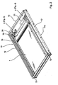
- FIG. 1 schematically designated 2 vehicle has in the region of the door entry a recess for receiving the designated cassette 10 for receiving the ramp 1.
- the cassette 10 here shows a cover plate 11, which forms the bottom of the vehicle, or is located under the floor of the vehicle , The designated 10 cassette will now be based on the Figures 2 ff. explained in more detail.
- the cassette 10 comprises two side walls 12, as well as a rear wall 13. Both the rear wall 13 and the side walls 12 together with the cover plate 11 (FIGS. Fig. 1
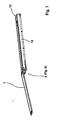
- the side walls 12 have longitudinal grooves 12a, in which the ramp 1 is guided parallel to the extension direction according to the double arrow 50 (FIG. Fig. 6 ).
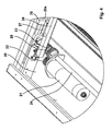
- the ramp 1 is connected by two toggle lever 70 in articulated connection with the carriage 20 (FIG. Fig.
- the carriage 20 will thus move along the two racks. Since the carriage 20 with the ramp 1 by the arranged on both sides bracket 27 and toggle lever 70 (FIG. Fig. 3 . Fig. 4 ) is in operation, the ramp 1, as well as the carriage 20 is extended in the direction of the double arrow 50 upon actuation of the drive motor 21. In this context is on the Fig. 6 which clearly shows the position of the carriage 20 at a partially extended ramp 1.
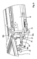
- the knee levers are arranged on both sides of the ramp and are both in articulated connection with the ramp 1 and with the carriage 20 (FIG. Fig. 8 ).
- the locking device 30 includes the locking bar 31 (FIG. FIG. 3 ), which has the locking block 33 at the end.
- the locking bar 31 is mounted in the bearing block 34, which is arranged on the rack 26.
- a compression spring 35 Between the bearing block 34 and the locking block 34 is a compression spring 35, wherein upon pulling the handle 36 ( Fig. 5 ) is pulled in the direction of the arrow 36a by the locking block 33 of the locking block 37, also in the direction of the arrow 36a, against the force of the spring 38, the locking block 37 has a slope 37a, which rests against the latch 40.
- the latch 40 has a locking pin 41 which is engageable with a corresponding bore 31 a of the rack 26 can be brought.
- a spring-loaded pressure piece 75 is provided.
- the spring-loaded pressure piece 75 comprises a sleeve 75c with the ball 75a loaded by a spring 75b.
- the stopper 72 has a cup-shaped recess 73 for the ball 75a of the pressure piece.
- the cassette has a groove 14a and the stopper 72 a spring 72a, wherein the spring 72a engages in the groove 14a ( Fig. 9, Fig. 10 ). If the two stops 72 are removed on both sides of the ramp, the ramp can be pulled out together with the slide and optionally replaced by another ramp.
- an electric motor 60 is provided which is in communication with the latch 40, wherein during operation of the electric motor, the bolt 40 with the locking bolt 41 is also brought out of engagement with the bore 31 a in the rack 26.
- a toggle lever 70 is attached to the ramp 1.
- the toggle 70 is, as this is in detail Fig. 8 results, with the carriage 20 by a joint 20a and with the ramp 1 by a joint 20b in combination. Moves the toggle lever 70 in the lying position, as in Fig. 2 shown against the arranged at the front end of the cassette stopper 72, then pivots the toggle lever 70 in the position according to Fig. 8 and, since he is with the At the other end is connected to the ramp 1, the ramp 1, so that it allows a surface-like transition from the ramp into the vehicle interior.
Landscapes
- Engineering & Computer Science (AREA)
- Mechanical Engineering (AREA)
- Lock And Its Accessories (AREA)
Priority Applications (3)
| Application Number | Priority Date | Filing Date | Title |
|---|---|---|---|
| EP10007038.2A EP2390142B1 (de) | 2010-05-31 | 2010-07-08 | Vorrichtung zur ausfahrbaren Aufnahme einer Rampe |
| PL10007038T PL2390142T3 (pl) | 2010-05-31 | 2010-07-08 | Urządzenie wysuwne do mocowania rampy |
| US13/118,698 US20120030886A1 (en) | 2010-05-31 | 2011-05-31 | Device for an extendable reception of a ramp |
Applications Claiming Priority (2)
| Application Number | Priority Date | Filing Date | Title |
|---|---|---|---|
| EP10005640 | 2010-05-31 | ||
| EP10007038.2A EP2390142B1 (de) | 2010-05-31 | 2010-07-08 | Vorrichtung zur ausfahrbaren Aufnahme einer Rampe |
Publications (2)
| Publication Number | Publication Date |
|---|---|
| EP2390142A1 EP2390142A1 (de) | 2011-11-30 |
| EP2390142B1 true EP2390142B1 (de) | 2013-07-31 |
Family
ID=43027624
Family Applications (1)
| Application Number | Title | Priority Date | Filing Date |
|---|---|---|---|
| EP10007038.2A Active EP2390142B1 (de) | 2010-05-31 | 2010-07-08 | Vorrichtung zur ausfahrbaren Aufnahme einer Rampe |
Country Status (3)
| Country | Link |
|---|---|
| US (1) | US20120030886A1 (pl) |
| EP (1) | EP2390142B1 (pl) |
| PL (1) | PL2390142T3 (pl) |
Families Citing this family (19)
| Publication number | Priority date | Publication date | Assignee | Title |
|---|---|---|---|---|
| CA2620211A1 (en) | 2007-02-01 | 2008-08-01 | Lift-U, Division Of Hogan Mfg., Inc. | Compact folding slide-out ramp assembly |
| DE202012008578U1 (de) | 2011-11-19 | 2012-11-20 | Hübner Transportation GmbH | Vorrichtung zur ausfahrbaren Aufnahme einer Rampe |
| KR101262910B1 (ko) * | 2012-08-27 | 2013-05-09 | 황성공업 주식회사 | 전동식 스텝장치 |
| US9966618B2 (en) | 2012-12-09 | 2018-05-08 | United Technologies Corporation | Flow battery with voltage-limiting device |
| KR101393916B1 (ko) * | 2013-05-07 | 2014-05-12 | 현대자동차주식회사 | 차량의 도어 스텝장치 |
| KR101500235B1 (ko) * | 2013-12-20 | 2015-03-06 | 현대자동차주식회사 | 차량용 사이드스텝 장치 |
| AT515195B1 (de) * | 2014-04-07 | 2015-07-15 | Knorr Bremse Gmbh Division Ife Automatic Door Systems | Bewegliches Trittbrett |
| ITFI20140055U1 (it) * | 2014-10-01 | 2016-04-01 | Nardini Davide | Gradino a scomparsa. |
| ITFI20140056U1 (it) * | 2014-10-01 | 2016-04-01 | Nardini Davide | Gradino estraibile. |
| US11056698B2 (en) | 2018-08-02 | 2021-07-06 | Raytheon Technologies Corporation | Redox flow battery with electrolyte balancing and compatibility enabling features |
| USD910938S1 (en) * | 2019-03-26 | 2021-02-16 | Vermont Juvenile Furniture Mfg., Inc. | Pet ramp |
| US11548428B2 (en) * | 2019-12-09 | 2023-01-10 | The Braun Corporation | Geared ramp assembly with raised ramp position and side rails and method of use |
| DE202020105492U1 (de) * | 2020-09-25 | 2022-01-07 | Gebr. Bode Gmbh & Co. Kg | Zustiegeinrichtung für ein Fahrzeug |
| US11271226B1 (en) | 2020-12-11 | 2022-03-08 | Raytheon Technologies Corporation | Redox flow battery with improved efficiency |
| JP7615881B2 (ja) * | 2021-05-19 | 2025-01-17 | 株式会社アイシン | 車両用スロープ装置 |
| USD987916S1 (en) * | 2021-07-14 | 2023-05-30 | Hefei Haimai Information Technology Co., Ltd. | Pet climbing platform |
| USD995955S1 (en) * | 2021-10-20 | 2023-08-15 | Ningbo Seedling Industry and Technology Pte. Ltd. | Animal saving escape ramp |
| US12617328B2 (en) * | 2021-11-12 | 2026-05-05 | National Fleet Products, Inc. | Loading ramp for utility vans |
| WO2024229418A1 (en) * | 2023-05-03 | 2024-11-07 | Node Systems Inc. | Transfer ramp systems for loading, unloading, or transferring cargo between one or more commercial vehicles and associated systems, devices, and methods |
Family Cites Families (9)
| Publication number | Priority date | Publication date | Assignee | Title |
|---|---|---|---|---|
| WO1998006370A1 (en) * | 1996-08-15 | 1998-02-19 | Tieman Industries Pty. Ltd. | A retractable ramp assembly |
| AU8902998A (en) * | 1997-08-22 | 1999-03-16 | Ricon Corporation | Movable ramp with controller |
| DE10043561B4 (de) | 2000-09-01 | 2007-09-27 | Hübner GmbH | Rampe für einen Türeinstieg |
| US6869092B1 (en) * | 2002-07-09 | 2005-03-22 | Chief Industries, Inc. | Slide-out deck for a recreational vehicle |
| BE1015086A6 (nl) * | 2002-08-29 | 2004-09-07 | Omnistor Accessories Nv | Uitschuifbare trede. |
| EP1621404A1 (en) * | 2004-07-30 | 2006-02-01 | Algonquin Automotive | Motorized rack and pinion assembly |
| DE202005012584U1 (de) | 2005-07-29 | 2005-12-01 | Hübner Transportation GmbH | Rampe für einen Türeinstieg eines Personenbeförderungsfahrzeugs |
| DE202006004644U1 (de) | 2006-03-23 | 2006-06-01 | Hübner Transportation GmbH | Rampe zur Anbringung im Bereich des Einstiegs eines Fahrzeuges, z.B. eines Busses |
| US7513565B2 (en) * | 2007-01-26 | 2009-04-07 | Magna International Inc. | Power dual action rocker board |
-
2010
- 2010-07-08 PL PL10007038T patent/PL2390142T3/pl unknown
- 2010-07-08 EP EP10007038.2A patent/EP2390142B1/de active Active
-
2011
- 2011-05-31 US US13/118,698 patent/US20120030886A1/en not_active Abandoned
Also Published As
| Publication number | Publication date |
|---|---|
| PL2390142T3 (pl) | 2014-02-28 |
| EP2390142A1 (de) | 2011-11-30 |
| US20120030886A1 (en) | 2012-02-09 |
Similar Documents
| Publication | Publication Date | Title |
|---|---|---|
| EP2390142A1 (de) | Vorrichtung zur ausfahrbaren Aufnahme einer Rampe | |
| EP3237254B1 (de) | Schiebetritt mit hub- und rampenfunktion | |
| EP2689964B1 (de) | Containerverriegelung | |
| DE3128010A1 (de) | "betaetigungseinrichtung fuer trichterverschlusstueren an eisenbahn-trichterwagen" | |
| EP1177948B1 (de) | Laderaumabdeckung für Kraftwagen, insbesondere für Kombinations-Personenkraftwagen | |
| EP3599129A1 (de) | Tischvorrichtung für ein kraftfahrzeug | |
| CH621976A5 (pl) | ||
| EP0941889B1 (de) | Ausziehvorrichtung | |
| DE102015108657B4 (de) | Fahrzeug mit einem Tragsystem | |
| DE102012104987B4 (de) | Außentritt für den Führerstand von Schienenfahrzeugen | |
| DE102006000619B4 (de) | Federbelastete Klinkensperre mit automatischer Rückstellung | |
| EP2766240B1 (de) | Passagierschienenfahrzeug | |
| DE202011100837U1 (de) | Flurförderzeug | |
| DE202018106885U1 (de) | Trittsystem für ein Fahrzeug | |
| DE202012008578U1 (de) | Vorrichtung zur ausfahrbaren Aufnahme einer Rampe | |
| DE3817220C1 (en) | Bolt lock | |
| DE102005029111B4 (de) | Dachreling für Fahrzeuge | |
| DE102014211492B4 (de) | Trittstufe für Kraftfahrzeuge | |
| DE102019001682B4 (de) | Fahrzeug, insbesondere Wohnmobil | |
| DE2639304C2 (de) | Schubladenschrank | |
| DE102015102025B4 (de) | Laderaumabdeckung | |
| DE102013018524B4 (de) | Ladeeinrichtung für ein Kraftfahrzeug | |
| EP2092848B1 (de) | Auszugeinrichtung zum Einsetzen in ein Schrankelement einer Möbeleinrichtung | |
| DE202018102688U1 (de) | Fahrzeug zum Befördern von Personen mit einer Transportfläche und einer mindestens zwei Funktionsstellungen umfassenden Rampe | |
| DE102019109727A1 (de) | Ladesystem zum elektrischen Laden von Elektrofahrzeugen oder Plug-in-Hybridfahrzeugen |
Legal Events
| Date | Code | Title | Description |
|---|---|---|---|
| 17P | Request for examination filed |
Effective date: 20110112 |
|
| AK | Designated contracting states |
Kind code of ref document: A1 Designated state(s): AL AT BE BG CH CY CZ DE DK EE ES FI FR GB GR HR HU IE IS IT LI LT LU LV MC MK MT NL NO PL PT RO SE SI SK SM TR |
|
| AX | Request for extension of the european patent |
Extension state: BA ME RS |
|
| PUAI | Public reference made under article 153(3) epc to a published international application that has entered the european phase |
Free format text: ORIGINAL CODE: 0009012 |
|
| RIC1 | Information provided on ipc code assigned before grant |
Ipc: B60R 3/02 20060101AFI20130115BHEP |
|
| GRAP | Despatch of communication of intention to grant a patent |
Free format text: ORIGINAL CODE: EPIDOSNIGR1 |
|
| GRAS | Grant fee paid |
Free format text: ORIGINAL CODE: EPIDOSNIGR3 |
|
| GRAA | (expected) grant |
Free format text: ORIGINAL CODE: 0009210 |
|
| AK | Designated contracting states |
Kind code of ref document: B1 Designated state(s): AL AT BE BG CH CY CZ DE DK EE ES FI FR GB GR HR HU IE IS IT LI LT LU LV MC MK MT NL NO PL PT RO SE SI SK SM TR |
|
| REG | Reference to a national code |
Ref country code: GB Ref legal event code: FG4D Free format text: NOT ENGLISH Ref country code: CH Ref legal event code: EP |
|
| REG | Reference to a national code |
Ref country code: AT Ref legal event code: REF Ref document number: 624407 Country of ref document: AT Kind code of ref document: T Effective date: 20130815 |
|
| REG | Reference to a national code |
Ref country code: IE Ref legal event code: FG4D Free format text: LANGUAGE OF EP DOCUMENT: GERMAN |
|
| REG | Reference to a national code |
Ref country code: DE Ref legal event code: R096 Ref document number: 502010004178 Country of ref document: DE Effective date: 20130926 |
|
| REG | Reference to a national code |
Ref country code: NL Ref legal event code: VDEP Effective date: 20130731 |
|
| REG | Reference to a national code |
Ref country code: LT Ref legal event code: MG4D |
|
| PG25 | Lapsed in a contracting state [announced via postgrant information from national office to epo] |
Ref country code: LT Free format text: LAPSE BECAUSE OF FAILURE TO SUBMIT A TRANSLATION OF THE DESCRIPTION OR TO PAY THE FEE WITHIN THE PRESCRIBED TIME-LIMIT Effective date: 20130731 Ref country code: HR Free format text: LAPSE BECAUSE OF FAILURE TO SUBMIT A TRANSLATION OF THE DESCRIPTION OR TO PAY THE FEE WITHIN THE PRESCRIBED TIME-LIMIT Effective date: 20130731 Ref country code: SE Free format text: LAPSE BECAUSE OF FAILURE TO SUBMIT A TRANSLATION OF THE DESCRIPTION OR TO PAY THE FEE WITHIN THE PRESCRIBED TIME-LIMIT Effective date: 20130731 Ref country code: NO Free format text: LAPSE BECAUSE OF FAILURE TO SUBMIT A TRANSLATION OF THE DESCRIPTION OR TO PAY THE FEE WITHIN THE PRESCRIBED TIME-LIMIT Effective date: 20131031 Ref country code: PT Free format text: LAPSE BECAUSE OF FAILURE TO SUBMIT A TRANSLATION OF THE DESCRIPTION OR TO PAY THE FEE WITHIN THE PRESCRIBED TIME-LIMIT Effective date: 20131202 Ref country code: CY Free format text: LAPSE BECAUSE OF FAILURE TO SUBMIT A TRANSLATION OF THE DESCRIPTION OR TO PAY THE FEE WITHIN THE PRESCRIBED TIME-LIMIT Effective date: 20130731 Ref country code: IS Free format text: LAPSE BECAUSE OF FAILURE TO SUBMIT A TRANSLATION OF THE DESCRIPTION OR TO PAY THE FEE WITHIN THE PRESCRIBED TIME-LIMIT Effective date: 20131130 |
|
| PG25 | Lapsed in a contracting state [announced via postgrant information from national office to epo] |
Ref country code: SI Free format text: LAPSE BECAUSE OF FAILURE TO SUBMIT A TRANSLATION OF THE DESCRIPTION OR TO PAY THE FEE WITHIN THE PRESCRIBED TIME-LIMIT Effective date: 20130731 Ref country code: NL Free format text: LAPSE BECAUSE OF FAILURE TO SUBMIT A TRANSLATION OF THE DESCRIPTION OR TO PAY THE FEE WITHIN THE PRESCRIBED TIME-LIMIT Effective date: 20130731 Ref country code: FI Free format text: LAPSE BECAUSE OF FAILURE TO SUBMIT A TRANSLATION OF THE DESCRIPTION OR TO PAY THE FEE WITHIN THE PRESCRIBED TIME-LIMIT Effective date: 20130731 Ref country code: LV Free format text: LAPSE BECAUSE OF FAILURE TO SUBMIT A TRANSLATION OF THE DESCRIPTION OR TO PAY THE FEE WITHIN THE PRESCRIBED TIME-LIMIT Effective date: 20130731 |
|
| REG | Reference to a national code |
Ref country code: PL Ref legal event code: T3 |
|
| PG25 | Lapsed in a contracting state [announced via postgrant information from national office to epo] |
Ref country code: EE Free format text: LAPSE BECAUSE OF FAILURE TO SUBMIT A TRANSLATION OF THE DESCRIPTION OR TO PAY THE FEE WITHIN THE PRESCRIBED TIME-LIMIT Effective date: 20130731 Ref country code: CZ Free format text: LAPSE BECAUSE OF FAILURE TO SUBMIT A TRANSLATION OF THE DESCRIPTION OR TO PAY THE FEE WITHIN THE PRESCRIBED TIME-LIMIT Effective date: 20130731 Ref country code: SK Free format text: LAPSE BECAUSE OF FAILURE TO SUBMIT A TRANSLATION OF THE DESCRIPTION OR TO PAY THE FEE WITHIN THE PRESCRIBED TIME-LIMIT Effective date: 20130731 Ref country code: RO Free format text: LAPSE BECAUSE OF FAILURE TO SUBMIT A TRANSLATION OF THE DESCRIPTION OR TO PAY THE FEE WITHIN THE PRESCRIBED TIME-LIMIT Effective date: 20130731 Ref country code: DK Free format text: LAPSE BECAUSE OF FAILURE TO SUBMIT A TRANSLATION OF THE DESCRIPTION OR TO PAY THE FEE WITHIN THE PRESCRIBED TIME-LIMIT Effective date: 20130731 |
|
| PG25 | Lapsed in a contracting state [announced via postgrant information from national office to epo] |
Ref country code: ES Free format text: LAPSE BECAUSE OF FAILURE TO SUBMIT A TRANSLATION OF THE DESCRIPTION OR TO PAY THE FEE WITHIN THE PRESCRIBED TIME-LIMIT Effective date: 20130731 |
|
| PLBE | No opposition filed within time limit |
Free format text: ORIGINAL CODE: 0009261 |
|
| STAA | Information on the status of an ep patent application or granted ep patent |
Free format text: STATUS: NO OPPOSITION FILED WITHIN TIME LIMIT |
|
| 26N | No opposition filed |
Effective date: 20140502 |
|
| REG | Reference to a national code |
Ref country code: DE Ref legal event code: R097 Ref document number: 502010004178 Country of ref document: DE Effective date: 20140502 |
|
| PG25 | Lapsed in a contracting state [announced via postgrant information from national office to epo] |
Ref country code: LU Free format text: LAPSE BECAUSE OF FAILURE TO SUBMIT A TRANSLATION OF THE DESCRIPTION OR TO PAY THE FEE WITHIN THE PRESCRIBED TIME-LIMIT Effective date: 20140708 |
|
| REG | Reference to a national code |
Ref country code: CH Ref legal event code: PL |
|
| REG | Reference to a national code |
Ref country code: IE Ref legal event code: MM4A |
|
| PG25 | Lapsed in a contracting state [announced via postgrant information from national office to epo] |
Ref country code: CH Free format text: LAPSE BECAUSE OF NON-PAYMENT OF DUE FEES Effective date: 20140731 Ref country code: LI Free format text: LAPSE BECAUSE OF NON-PAYMENT OF DUE FEES Effective date: 20140731 |
|
| PG25 | Lapsed in a contracting state [announced via postgrant information from national office to epo] |
Ref country code: IE Free format text: LAPSE BECAUSE OF NON-PAYMENT OF DUE FEES Effective date: 20140708 |
|
| PG25 | Lapsed in a contracting state [announced via postgrant information from national office to epo] |
Ref country code: MC Free format text: LAPSE BECAUSE OF FAILURE TO SUBMIT A TRANSLATION OF THE DESCRIPTION OR TO PAY THE FEE WITHIN THE PRESCRIBED TIME-LIMIT Effective date: 20130731 Ref country code: SM Free format text: LAPSE BECAUSE OF FAILURE TO SUBMIT A TRANSLATION OF THE DESCRIPTION OR TO PAY THE FEE WITHIN THE PRESCRIBED TIME-LIMIT Effective date: 20130731 |
|
| PG25 | Lapsed in a contracting state [announced via postgrant information from national office to epo] |
Ref country code: BG Free format text: LAPSE BECAUSE OF FAILURE TO SUBMIT A TRANSLATION OF THE DESCRIPTION OR TO PAY THE FEE WITHIN THE PRESCRIBED TIME-LIMIT Effective date: 20130731 Ref country code: MT Free format text: LAPSE BECAUSE OF FAILURE TO SUBMIT A TRANSLATION OF THE DESCRIPTION OR TO PAY THE FEE WITHIN THE PRESCRIBED TIME-LIMIT Effective date: 20130731 Ref country code: GR Free format text: LAPSE BECAUSE OF FAILURE TO SUBMIT A TRANSLATION OF THE DESCRIPTION OR TO PAY THE FEE WITHIN THE PRESCRIBED TIME-LIMIT Effective date: 20130731 |
|
| REG | Reference to a national code |
Ref country code: FR Ref legal event code: PLFP Year of fee payment: 7 |
|
| PG25 | Lapsed in a contracting state [announced via postgrant information from national office to epo] |
Ref country code: HU Free format text: LAPSE BECAUSE OF FAILURE TO SUBMIT A TRANSLATION OF THE DESCRIPTION OR TO PAY THE FEE WITHIN THE PRESCRIBED TIME-LIMIT; INVALID AB INITIO Effective date: 20100708 Ref country code: BE Free format text: LAPSE BECAUSE OF FAILURE TO SUBMIT A TRANSLATION OF THE DESCRIPTION OR TO PAY THE FEE WITHIN THE PRESCRIBED TIME-LIMIT Effective date: 20140731 |
|
| REG | Reference to a national code |
Ref country code: AT Ref legal event code: MM01 Ref document number: 624407 Country of ref document: AT Kind code of ref document: T Effective date: 20150708 |
|
| PG25 | Lapsed in a contracting state [announced via postgrant information from national office to epo] |
Ref country code: AT Free format text: LAPSE BECAUSE OF NON-PAYMENT OF DUE FEES Effective date: 20150708 |
|
| REG | Reference to a national code |
Ref country code: FR Ref legal event code: PLFP Year of fee payment: 8 |
|
| PG25 | Lapsed in a contracting state [announced via postgrant information from national office to epo] |
Ref country code: MK Free format text: LAPSE BECAUSE OF FAILURE TO SUBMIT A TRANSLATION OF THE DESCRIPTION OR TO PAY THE FEE WITHIN THE PRESCRIBED TIME-LIMIT Effective date: 20130731 |
|
| REG | Reference to a national code |
Ref country code: FR Ref legal event code: PLFP Year of fee payment: 9 |
|
| PG25 | Lapsed in a contracting state [announced via postgrant information from national office to epo] |
Ref country code: AL Free format text: LAPSE BECAUSE OF FAILURE TO SUBMIT A TRANSLATION OF THE DESCRIPTION OR TO PAY THE FEE WITHIN THE PRESCRIBED TIME-LIMIT Effective date: 20130731 |
|
| PGFP | Annual fee paid to national office [announced via postgrant information from national office to epo] |
Ref country code: DE Payment date: 20250722 Year of fee payment: 16 |
|
| PGFP | Annual fee paid to national office [announced via postgrant information from national office to epo] |
Ref country code: IT Payment date: 20250731 Year of fee payment: 16 Ref country code: TR Payment date: 20250702 Year of fee payment: 16 |
|
| PGFP | Annual fee paid to national office [announced via postgrant information from national office to epo] |
Ref country code: GB Payment date: 20250724 Year of fee payment: 16 |
|
| PGFP | Annual fee paid to national office [announced via postgrant information from national office to epo] |
Ref country code: FR Payment date: 20250723 Year of fee payment: 16 |
|
| REG | Reference to a national code |
Ref country code: DE Ref legal event code: R081 Ref document number: 502010004178 Country of ref document: DE Owner name: HUEBNER GMBH & CO. KG, DE Free format text: FORMER OWNER: HUEBNER TRANSPORTATION GBMH, 34123 KASSEL, DE Ref country code: DE Ref legal event code: R082 Ref document number: 502010004178 Country of ref document: DE |
|
| REG | Reference to a national code |
Ref country code: GB Ref legal event code: 732E Free format text: REGISTERED BETWEEN 20260409 AND 20260415 |
|
| PGFP | Annual fee paid to national office [announced via postgrant information from national office to epo] |
Ref country code: PL Payment date: 20260626 Year of fee payment: 17 |