EP2390134A1 - Vorrichtung zur Montage eines Kugelgelenks eines Fahrzeugscheinwerferreflektors, verbesserter Scheinwerfer mit dieser Vorrichtung und Fahrzeug mit diesem Scheinwerfer - Google Patents
Vorrichtung zur Montage eines Kugelgelenks eines Fahrzeugscheinwerferreflektors, verbesserter Scheinwerfer mit dieser Vorrichtung und Fahrzeug mit diesem Scheinwerfer Download PDFInfo
- Publication number
- EP2390134A1 EP2390134A1 EP11167553A EP11167553A EP2390134A1 EP 2390134 A1 EP2390134 A1 EP 2390134A1 EP 11167553 A EP11167553 A EP 11167553A EP 11167553 A EP11167553 A EP 11167553A EP 2390134 A1 EP2390134 A1 EP 2390134A1
- Authority
- EP
- European Patent Office
- Prior art keywords
- spherical
- seat
- shank
- reflector
- pin
- Prior art date
- Legal status (The legal status is an assumption and is not a legal conclusion. Google has not performed a legal analysis and makes no representation as to the accuracy of the status listed.)
- Granted
Links
- 239000000463 material Substances 0.000 claims description 7
- 239000002184 metal Substances 0.000 description 2
- 238000000034 method Methods 0.000 description 2
- 238000004873 anchoring Methods 0.000 description 1
- 238000005452 bending Methods 0.000 description 1
- 238000010276 construction Methods 0.000 description 1
- 229910052736 halogen Inorganic materials 0.000 description 1
- 150000002367 halogens Chemical class 0.000 description 1
- 230000002452 interceptive effect Effects 0.000 description 1
- 238000004519 manufacturing process Methods 0.000 description 1
- 238000011084 recovery Methods 0.000 description 1
- 239000000725 suspension Substances 0.000 description 1
Images

Classifications
-
- B—PERFORMING OPERATIONS; TRANSPORTING
- B60—VEHICLES IN GENERAL
- B60Q—ARRANGEMENT OF SIGNALLING OR LIGHTING DEVICES, THE MOUNTING OR SUPPORTING THEREOF OR CIRCUITS THEREFOR, FOR VEHICLES IN GENERAL
- B60Q1/00—Arrangement of optical signalling or lighting devices, the mounting or supporting thereof or circuits therefor
- B60Q1/02—Arrangement of optical signalling or lighting devices, the mounting or supporting thereof or circuits therefor the devices being primarily intended to illuminate the way ahead or to illuminate other areas of way or environments
- B60Q1/04—Arrangement of optical signalling or lighting devices, the mounting or supporting thereof or circuits therefor the devices being primarily intended to illuminate the way ahead or to illuminate other areas of way or environments the devices being headlights
- B60Q1/06—Arrangement of optical signalling or lighting devices, the mounting or supporting thereof or circuits therefor the devices being primarily intended to illuminate the way ahead or to illuminate other areas of way or environments the devices being headlights adjustable, e.g. remotely-controlled from inside vehicle
-
- B—PERFORMING OPERATIONS; TRANSPORTING
- B60—VEHICLES IN GENERAL
- B60Q—ARRANGEMENT OF SIGNALLING OR LIGHTING DEVICES, THE MOUNTING OR SUPPORTING THEREOF OR CIRCUITS THEREFOR, FOR VEHICLES IN GENERAL
- B60Q2200/00—Special features or arrangements of vehicle headlamps
- B60Q2200/30—Special arrangements for adjusting headlamps, e.g. means for transmitting the movements for adjusting the lamps
- B60Q2200/32—Ball-joints
Definitions
- the present invention relates to an assembly device for a spherical joint of a reflector of a vehicle headlamp.
- the invention is also relative to an improved headlamp provided with said device for supporting the reflector on the headlamp body and a vehicle provided with said headlamp.
- Motor vehicle headlamps generally comprise a cup-shaped body closed at the front by a clear or prismed lens, and housing on its interior a reflector for the light source, which is supported tilting by the headlamp body by a three stems suspension system, each of which is equipped with a spherical joint and at least one of which is axially movable by way of an adjusting device.
- the spherical joint through which each stem is constrained to the reflector comprises a spherical head carried by the stem and an elastically deformable block, typically made of synthetic plastic material, defining within its interior a spherical seat to snappingly receive the spherical head of the stem.
- the blocks of the spherical joints are not obtained in one piece with the reflector, but they are separate elements, secured in the rear of the reflector by way of linking elements, such as screws.
- the reflector In order to assemble the blocks, therefore, the reflector must be provided with feet defined by sleeves obtained integrally in one piece with the reflector upon which blocks are assembled laterally overhanging, an assembly on the axis of the spherical seat of the block with respective feet is of course hindered by the need to leave the fixing screw uncovered or otherwise easily accessible.
- the invention is thus related to a device for assembling a spherical joint for a reflector of a vehicle headlamp as defined in claim 1.
- the invention is also related to a vehicle headlamp provided with said assembly device, as defined in claim 12, and a vehicle as defined in claim 13.
- the assembly device comprises a tubular shank obtained in one piece with the block and which overhangingly extends therefrom, in the direction of an axis for introducing the spherical head in the spherical seat and from the opposite side to the seat; the tubular shank is formed by at least one pair of fins, which are elastically deformable in a radial direction to the introduction axis;
- the device of the invention also comprises, in combination, a reception seat for the shank, which is obtained in one piece with the reflector; and a pin, that is shaped so as to be adapted for selectively taking a first position, in which the pin is aligned with the shank at a mouth thereof facing on the side of the spherical seat and is connected in one piece to the block through a cuttable diaphragm, and a second position in which the pin is at least partially driven into the tubular shank and interferes with the elastically deformable fins to such an extent that, when the shank is
- the tubular shank and the pin are directly carried by the block, axially aligned with each other and both arranged to be coaxial with the spherical seat so that the interior of the tubular shank directly communicates with the spherical seat, in a position immediately underlying it, by way of said mouth, and so that at least part of the pin, in the first position of the latter, is housed within said first spherical seat so as to protrude axially therein.
- the cuttable diaphragm consists of at least one thinned portion and, therefore of reduced thickness, of a bottom wall of the spherical seat.
- the assembly device is relatively low cost, quickly assembled and highly reliable, being risk-free of the typical loosening of threaded joints.
- the pin once the cuttable diaphragm is cut due to the introduction of the spherical head of the stem in its spherical seat in the block, it behaves like the well-known connecting element called "prisoner", but that is usually made of a full section metal threaded shank that is interferingly driven into a hole in a metal sheet or plate. It therefore holds the fins forming the elastically deformable shank of the block pressed against the sidewall of the reception seat, preventing any accidental removal or loosening of the connection between the headlamp body and the headlamp.
- FIG. 1 indicated as a whole with 1 is an assembly device of a spherical joint 2 for a reflector 3 of a front headlamp 4 for a vehicle 5 of any known type, in which is illustrated for simplicity only part of the front profile thereof.
- the vehicle headlamp 4 comprises a headlamp body 6 substantially cup-shaped and closed at the front by a clear or prismed lens 7, a light source 8, for example an incandescent bulb, halogen or a gas-discharge lamp or a LED, and the reflector 3, which serves to channel the light rays emitted from the source 8 towards the lens 7 according to a predetermined photometric distribution.
- the reflector 3 for the light source 8 is arranged inside of the headlamp 6 and is supported by the latter by at least three spherical joints 2, according to a known scheme, of which only one is shown for simplicity, out of scale.
- Each joint or spherical joint 2 comprises a spherical head 9 securable to the headlamp body, in this case self-carried by the headlamp body 6 by way of a respective stem 10 and a block 11 integrally carried by the reflector 3 and internally provided with a spherical seat 12 adapted to snappingly engage, in use, the spherical head 9.
- the shown spherical joint 2 is the one supported on the headlamp body 6 by a stem 10 axially movable, along an axis A, by a known adjusting device 13, schematically shown with a block.
- the block 11 in the complex of known structure, defines the spherical seat 12 via at least one pair of elastically deformable sectors 12b detached on the block 11 by respective known slits and not shown for simplicity.
- the blocks 11 of all the spherical joints 2 are made as separate items from the reflector 3, but securable to the latter as will be seen; in this case the blocks 11 are secured to the reflector 3 each by a respective assembly device 1.
- Each assembly device 1 comprises, in combination, a tubular shank 14 obtained in one piece with the respective block 11 and which overhangingly extends therefrom, in the direction of an axis for introducing the spherical head 9 into the spherical seat 12, in the case illustrated formed by the axis A; and a seat 15 for receiving the shank 14 obtained in one piece with the reflector 3; in particular, the tubular shank 14 extends from the block 11 from the opposite side of the spherical seat 12 and is formed by at least a couple of fins 16 which are elastically deformable in a direction radial to the introduction axis A.
- the device 1 further comprises a pin 17 adapted to selectively assume two different operating positions.
- a pin 17 adapted to selectively assume two different operating positions.
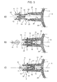
- the pin 17 In a first position, illustrated in figure 3a , the pin 17 is aligned with the shank 14 at a mouth or inlet opening 18 ( Figure 1 ) thereof facing the spherical seat 12 and is connected in one piece to the block 11 through a cuttable diaphragm 19 ( Figures 3a and 3b ).
- the pin 17 is instead at least partially driven within the tubular shank 14 and interferes with the elastically deformable fins 16 to such an extent that, when the shank 14 is inserted in the reception seat 15 of the reflector 3, the fins 16 interfere with a sidewall 20 of the reception seat 15.
- the tubular shank 14 and the pin 17 are directly carried by the block 11, axially aligned with each other and both arranged coaxially with the spherical seat 12 and the stem 10, along the axis A, so that the interior of the tubular shank 14 directly communicates with the spherical seat 12, in a position immediately beneath the same, through the mouth 18, and so that at least part of the pin 17, in the first position of the latter ( Figures 3a and 3b ), is axially overhangingly housed within the spherical seat 12.
- the cuttable diaphragm 19 consists of at least one thinned portion, therefore, of reduced thickness, of a bottom wall 21 ( Figure 1 ) of the spherical seat 12.
- the pin 17 has a first end portion 22 adapted to cooperate with the spherical head 9 when the latter is snappingly introduced in the spherical seat 12 and a second end portion 23, opposite to the first end portion 22 and transversally larger in size than the first portion 22, adapted to cooperate in the second pin position, with the elastically deformable fins 16 of the tubular shank 14, from the interior of the latter, to press them against the sidewall 20 of the reception seat 15 of the shank 14.
- the cuttable diaphragm 19 is obtained in one piece with the pin 17, between the end portions 22 and 23 thereof.
- the second end portion 23 of the pin 17 ( Figure 2 ) is provided laterally on the outside of the pin 17, i.e. towards the fins 16 of the tubular shank 14, with the respective longitudinal ribs 24, shown with dotted lines.
- the elastically deformable fins 16 forming the tubular shank are shaped so that, with the fins 16 not deformed, they have respective ends 25 overhangingly diverging from one another ( Figure 3a ), so that the dimensions of the tubular shank 14 are, at least for part of its length, larger than the one of the reception seat 15 carried by the reflector 3.
- the elastically deformable fins 16 forming the tubular shank have their respective overhanging ends 25 radially provided on the interior of the tubular shank 14 of respective stop teeth 26 for the pin 17 ( Figure 2 ), which are adapted to axially abut against the same when the pin 17 is in the second operational position of Figures 1 and 3c .
- the elastically deformable fins 16 are radially provided on the exterior of the tubular shank 14, of protruding elements 27 adapted to be anchored in use to the sidewall 20 of the reception seat 15 carried by the reflector 3.
- the reception seat 15 for the tubular shank 14 is defined by a sleeve 28 carried by a rear wall 29 of the reflector 3, so as to protrude; also, the fins 16 of the tubular shank 14 are made of a harder material than the material of the sleeve 28.
- both elements, i.e. the sleeve 28 and the shank 14 are made of a molded synthetic plastic material, as well as the block 11 and the pin 17.
- each spherical joint 2 is obtained in one piece with the shank 14 and the pin 17, as shown in figure 3a .
- the shank 14 is inserted in the seat 15 ( Figure 3b ), which produces the partial bending of the fins 16 towards the axis A; the latter elastically respond, exerting pressure against the wall 20, thus maintaining the block 11 locked on the reflector 3 by friction.
- the spherical heads 9 are to be introduced into the seats 12 of blocks 11 forming spherical joints 2; in so doing, however, the spherical head 9, by being introduced in the seat 12 already in part occupied by the end 22 of the pin 17, goes to intercept the latter, pushing the pin 17 towards the shank 14; the thrust, equivalently to the normal one of the snapping introduction of the head 9 in the seat 12, is such that the diaphragm 19, which is extremely weak, is cut, therefore allowing the head 9 and the respective stem 10 to push the pin 17 almost entirely within the shank 14; the portion 23 of the pin 17 then moves to abut against the teeth 26 and is driven in interference, also due to the influence of the rib 24, between the fins 16.
- the pin 17 results driven in interference in the shank 14 and the latter is driven in interference in the seat 15, thus anchoring the block 11 to the reflector 3 as if it had been obtained in one piece with the same, all without the use of screws or other threaded elements and in a quick way, basically executing the same assembly procedure of the spherical joints 2.
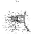
- the device 1b is substantially similar to device 1, also comprising a shank 14 consisting of at least a pair of elastically deformable fins 16, within which a pin 17 is introducible in use, having a thickened end 23 adapted for expanding the fins 16.
- the shank 14, similarly to the device 1, is introducible in the seat 15 of the sleeve 28, integral with the reflector 3.
- the pin 17 and shank 14 are aligned with the spherical seat 12 along the axis A
- the pin 17 and the shank 14 are aligned with each other, but along an axis B parallel to axis A and laterally placed with respect to the seat 12.
- they are carried by means of a bracket 50 integrally carried in one piece by the block 11, laterally overhanging therefrom, laterally to the spherical seat 12; the bracket 50 is provided with a sleeve 51 facing the side of the concavity of the seat 12, i.e.
- the interior of the shank 14 is connected to the inside of the sleeve 51 through a bottom wall 52 of the sleeve 51 integral to the bracket 50 and crossed by the pin 17, which is connected to the bracket 50 via athinned portion of the bottom wall 52, not shown for simplicity, that forms an easily cuttable diaphragm completely similar to the diaphragm 19.
- the block 11 is integrally assembled to the reflector 3 forcibly driving the shank 14 within the seat 15, while the pin 17 remains in the first position. Successively, it is necessary to insert, as previously described, the pin 17 almost completely within the shank 14, bringing it to the second position, previously breaking the portion of the wall 52 defining the aforementioned cuttable diaphragm.
Landscapes
- Engineering & Computer Science (AREA)
- Mechanical Engineering (AREA)
- Non-Portable Lighting Devices Or Systems Thereof (AREA)
Applications Claiming Priority (1)
| Application Number | Priority Date | Filing Date | Title |
|---|---|---|---|
| ITTO2010A000434A IT1400173B1 (it) | 2010-05-25 | 2010-05-25 | Dispositivo di montaggio per uno snodo sferico di un riflettore di un proiettore per veicoli, proiettore perfezionato includente tale dispositivo e veicolo equipaggiato con un tale proiettore. |
Publications (2)
| Publication Number | Publication Date |
|---|---|
| EP2390134A1 true EP2390134A1 (de) | 2011-11-30 |
| EP2390134B1 EP2390134B1 (de) | 2013-05-08 |
Family
ID=43332544
Family Applications (1)
| Application Number | Title | Priority Date | Filing Date |
|---|---|---|---|
| EP20110167553 Active EP2390134B1 (de) | 2010-05-25 | 2011-05-25 | Vorrichtung zur Montage eines Kugelgelenks eines Fahrzeugscheinwerferreflektors, verbesserter Scheinwerfer mit dieser Vorrichtung und Fahrzeug mit diesem Scheinwerfer |
Country Status (2)
| Country | Link |
|---|---|
| EP (1) | EP2390134B1 (de) |
| IT (1) | IT1400173B1 (de) |
Cited By (1)
| Publication number | Priority date | Publication date | Assignee | Title |
|---|---|---|---|---|
| DE102023111102A1 (de) * | 2023-04-28 | 2024-10-31 | Ejot Se & Co. Kg | Baugruppe zur Bereitstellung eines Anbindungspunktes |
Citations (3)
| Publication number | Priority date | Publication date | Assignee | Title |
|---|---|---|---|---|
| EP0430814A1 (de) * | 1989-12-01 | 1991-06-05 | Valeo Vision | Kapsel, insbesondere zur Montage eines Stellschraubenkopfs für die Einstellung eines Reflektors eines Automobilscheinwerfers |
| DE19960528A1 (de) * | 1998-12-16 | 2000-06-21 | Valeo Vision | Befestigungszwischenstück zur Befestigung eines Reflektors an einem Abstützteil eines Scheinwerfers und Scheinwerfer mit einem solchen Zwischenstück |
| US6692176B1 (en) * | 2002-04-02 | 2004-02-17 | Asyst Technologies Llc | Ball socket with locking feature |
-
2010
- 2010-05-25 IT ITTO2010A000434A patent/IT1400173B1/it active
-
2011
- 2011-05-25 EP EP20110167553 patent/EP2390134B1/de active Active
Patent Citations (3)
| Publication number | Priority date | Publication date | Assignee | Title |
|---|---|---|---|---|
| EP0430814A1 (de) * | 1989-12-01 | 1991-06-05 | Valeo Vision | Kapsel, insbesondere zur Montage eines Stellschraubenkopfs für die Einstellung eines Reflektors eines Automobilscheinwerfers |
| DE19960528A1 (de) * | 1998-12-16 | 2000-06-21 | Valeo Vision | Befestigungszwischenstück zur Befestigung eines Reflektors an einem Abstützteil eines Scheinwerfers und Scheinwerfer mit einem solchen Zwischenstück |
| US6692176B1 (en) * | 2002-04-02 | 2004-02-17 | Asyst Technologies Llc | Ball socket with locking feature |
Cited By (1)
| Publication number | Priority date | Publication date | Assignee | Title |
|---|---|---|---|---|
| DE102023111102A1 (de) * | 2023-04-28 | 2024-10-31 | Ejot Se & Co. Kg | Baugruppe zur Bereitstellung eines Anbindungspunktes |
Also Published As
| Publication number | Publication date |
|---|---|
| EP2390134B1 (de) | 2013-05-08 |
| ITTO20100434A1 (it) | 2011-11-26 |
| IT1400173B1 (it) | 2013-05-17 |
Similar Documents
| Publication | Publication Date | Title |
|---|---|---|
| KR100440518B1 (ko) | 리플렉터 가동형 자동차용 헤드 램프 | |
| US6746142B2 (en) | Headlamp for automobile with aiming screw having locking portion | |
| US7762686B2 (en) | Lamp adjuster | |
| JPH0311482B2 (de) | ||
| JP2005508778A (ja) | 自動車の機器モジュール | |
| CN110285383A (zh) | 具备led光导功能的车灯组件和具有其的车辆 | |
| KR101740268B1 (ko) | 자동차용 ohc 램프 플레이트 | |
| EP2390134B1 (de) | Vorrichtung zur Montage eines Kugelgelenks eines Fahrzeugscheinwerferreflektors, verbesserter Scheinwerfer mit dieser Vorrichtung und Fahrzeug mit diesem Scheinwerfer | |
| US5388307A (en) | Shaft retaining collar | |
| US7438457B2 (en) | Input shaft for a lamp adjuster | |
| EP3650745B1 (de) | Beleuchtungsvorrichtung für fahrzeuge mit lichtleitern | |
| US20060230858A1 (en) | Shift lever device | |
| KR101447165B1 (ko) | 브레이크 라이트 센서 모듈 | |
| JP2006021670A (ja) | 車両用室内照明灯 | |
| US6183113B1 (en) | Halogen lamp | |
| KR101498484B1 (ko) | 자동차 안개등의 조사각도 조절장치 및 그 조립방법 | |
| CN1644981B (zh) | 汽车前照灯的装配工具 | |
| US7871190B2 (en) | Headlight comprising a fixed attached support element on which a reflector is pivotally mounted | |
| KR200325474Y1 (ko) | 벌브홀더를 갖춘 차량 전조등용 가스방전램프 | |
| EP0596428A1 (de) | Scheinwerfer für Fahrzeuge | |
| KR20060106456A (ko) | 차량의 리어 콤비네이션 램프 취부 구조 | |
| JP2012119319A (ja) | 自動車用の照明装置 | |
| US3560733A (en) | Take-apart lamp harp | |
| US11371594B1 (en) | Supplemental driver assembly for adjuster | |
| JP5302780B2 (ja) | 車輌用灯具及び車輌用灯具の組立方法 |
Legal Events
| Date | Code | Title | Description |
|---|---|---|---|
| AK | Designated contracting states |
Kind code of ref document: A1 Designated state(s): AL AT BE BG CH CY CZ DE DK EE ES FI FR GB GR HR HU IE IS IT LI LT LU LV MC MK MT NL NO PL PT RO RS SE SI SK SM TR |
|
| AX | Request for extension of the european patent |
Extension state: BA ME |
|
| PUAI | Public reference made under article 153(3) epc to a published international application that has entered the european phase |
Free format text: ORIGINAL CODE: 0009012 |
|
| 17P | Request for examination filed |
Effective date: 20120530 |
|
| GRAP | Despatch of communication of intention to grant a patent |
Free format text: ORIGINAL CODE: EPIDOSNIGR1 |
|
| RIC1 | Information provided on ipc code assigned before grant |
Ipc: B60Q 1/06 20060101AFI20121031BHEP |
|
| GRAS | Grant fee paid |
Free format text: ORIGINAL CODE: EPIDOSNIGR3 |
|
| GRAA | (expected) grant |
Free format text: ORIGINAL CODE: 0009210 |
|
| AK | Designated contracting states |
Kind code of ref document: B1 Designated state(s): AL AT BE BG CH CY CZ DE DK EE ES FI FR GB GR HR HU IE IS IT LI LT LU LV MC MK MT NL NO PL PT RO RS SE SI SK SM TR |
|
| REG | Reference to a national code |
Ref country code: GB Ref legal event code: FG4D |
|
| REG | Reference to a national code |
Ref country code: AT Ref legal event code: REF Ref document number: 610907 Country of ref document: AT Kind code of ref document: T Effective date: 20130515 Ref country code: CH Ref legal event code: EP |
|
| REG | Reference to a national code |
Ref country code: IE Ref legal event code: FG4D |
|
| REG | Reference to a national code |
Ref country code: DE Ref legal event code: R096 Ref document number: 602011001604 Country of ref document: DE Effective date: 20130704 |
|
| REG | Reference to a national code |
Ref country code: AT Ref legal event code: MK05 Ref document number: 610907 Country of ref document: AT Kind code of ref document: T Effective date: 20130508 |
|
| REG | Reference to a national code |
Ref country code: LT Ref legal event code: MG4D |
|
| REG | Reference to a national code |
Ref country code: NL Ref legal event code: VDEP Effective date: 20130508 |
|
| PG25 | Lapsed in a contracting state [announced via postgrant information from national office to epo] |
Ref country code: ES Free format text: LAPSE BECAUSE OF FAILURE TO SUBMIT A TRANSLATION OF THE DESCRIPTION OR TO PAY THE FEE WITHIN THE PRESCRIBED TIME-LIMIT Effective date: 20130819 Ref country code: SI Free format text: LAPSE BECAUSE OF FAILURE TO SUBMIT A TRANSLATION OF THE DESCRIPTION OR TO PAY THE FEE WITHIN THE PRESCRIBED TIME-LIMIT Effective date: 20130508 Ref country code: NO Free format text: LAPSE BECAUSE OF FAILURE TO SUBMIT A TRANSLATION OF THE DESCRIPTION OR TO PAY THE FEE WITHIN THE PRESCRIBED TIME-LIMIT Effective date: 20130808 Ref country code: GR Free format text: LAPSE BECAUSE OF FAILURE TO SUBMIT A TRANSLATION OF THE DESCRIPTION OR TO PAY THE FEE WITHIN THE PRESCRIBED TIME-LIMIT Effective date: 20130809 Ref country code: PT Free format text: LAPSE BECAUSE OF FAILURE TO SUBMIT A TRANSLATION OF THE DESCRIPTION OR TO PAY THE FEE WITHIN THE PRESCRIBED TIME-LIMIT Effective date: 20130909 Ref country code: SE Free format text: LAPSE BECAUSE OF FAILURE TO SUBMIT A TRANSLATION OF THE DESCRIPTION OR TO PAY THE FEE WITHIN THE PRESCRIBED TIME-LIMIT Effective date: 20130508 Ref country code: IS Free format text: LAPSE BECAUSE OF FAILURE TO SUBMIT A TRANSLATION OF THE DESCRIPTION OR TO PAY THE FEE WITHIN THE PRESCRIBED TIME-LIMIT Effective date: 20130908 Ref country code: AT Free format text: LAPSE BECAUSE OF FAILURE TO SUBMIT A TRANSLATION OF THE DESCRIPTION OR TO PAY THE FEE WITHIN THE PRESCRIBED TIME-LIMIT Effective date: 20130508 Ref country code: LT Free format text: LAPSE BECAUSE OF FAILURE TO SUBMIT A TRANSLATION OF THE DESCRIPTION OR TO PAY THE FEE WITHIN THE PRESCRIBED TIME-LIMIT Effective date: 20130508 Ref country code: FI Free format text: LAPSE BECAUSE OF FAILURE TO SUBMIT A TRANSLATION OF THE DESCRIPTION OR TO PAY THE FEE WITHIN THE PRESCRIBED TIME-LIMIT Effective date: 20130508 |
|
| PG25 | Lapsed in a contracting state [announced via postgrant information from national office to epo] |
Ref country code: PL Free format text: LAPSE BECAUSE OF FAILURE TO SUBMIT A TRANSLATION OF THE DESCRIPTION OR TO PAY THE FEE WITHIN THE PRESCRIBED TIME-LIMIT Effective date: 20130508 Ref country code: HR Free format text: LAPSE BECAUSE OF FAILURE TO SUBMIT A TRANSLATION OF THE DESCRIPTION OR TO PAY THE FEE WITHIN THE PRESCRIBED TIME-LIMIT Effective date: 20130508 Ref country code: RS Free format text: LAPSE BECAUSE OF FAILURE TO SUBMIT A TRANSLATION OF THE DESCRIPTION OR TO PAY THE FEE WITHIN THE PRESCRIBED TIME-LIMIT Effective date: 20130508 Ref country code: CY Free format text: LAPSE BECAUSE OF FAILURE TO SUBMIT A TRANSLATION OF THE DESCRIPTION OR TO PAY THE FEE WITHIN THE PRESCRIBED TIME-LIMIT Effective date: 20130508 Ref country code: BG Free format text: LAPSE BECAUSE OF FAILURE TO SUBMIT A TRANSLATION OF THE DESCRIPTION OR TO PAY THE FEE WITHIN THE PRESCRIBED TIME-LIMIT Effective date: 20130808 |
|
| PG25 | Lapsed in a contracting state [announced via postgrant information from national office to epo] |
Ref country code: LV Free format text: LAPSE BECAUSE OF FAILURE TO SUBMIT A TRANSLATION OF THE DESCRIPTION OR TO PAY THE FEE WITHIN THE PRESCRIBED TIME-LIMIT Effective date: 20130508 |
|
| PG25 | Lapsed in a contracting state [announced via postgrant information from national office to epo] |
Ref country code: DK Free format text: LAPSE BECAUSE OF FAILURE TO SUBMIT A TRANSLATION OF THE DESCRIPTION OR TO PAY THE FEE WITHIN THE PRESCRIBED TIME-LIMIT Effective date: 20130508 Ref country code: SK Free format text: LAPSE BECAUSE OF FAILURE TO SUBMIT A TRANSLATION OF THE DESCRIPTION OR TO PAY THE FEE WITHIN THE PRESCRIBED TIME-LIMIT Effective date: 20130508 Ref country code: EE Free format text: LAPSE BECAUSE OF FAILURE TO SUBMIT A TRANSLATION OF THE DESCRIPTION OR TO PAY THE FEE WITHIN THE PRESCRIBED TIME-LIMIT Effective date: 20130508 Ref country code: CZ Free format text: LAPSE BECAUSE OF FAILURE TO SUBMIT A TRANSLATION OF THE DESCRIPTION OR TO PAY THE FEE WITHIN THE PRESCRIBED TIME-LIMIT Effective date: 20130508 Ref country code: BE Free format text: LAPSE BECAUSE OF FAILURE TO SUBMIT A TRANSLATION OF THE DESCRIPTION OR TO PAY THE FEE WITHIN THE PRESCRIBED TIME-LIMIT Effective date: 20130508 |
|
| REG | Reference to a national code |
Ref country code: IE Ref legal event code: MM4A |
|
| PG25 | Lapsed in a contracting state [announced via postgrant information from national office to epo] |
Ref country code: RO Free format text: LAPSE BECAUSE OF FAILURE TO SUBMIT A TRANSLATION OF THE DESCRIPTION OR TO PAY THE FEE WITHIN THE PRESCRIBED TIME-LIMIT Effective date: 20130508 Ref country code: NL Free format text: LAPSE BECAUSE OF FAILURE TO SUBMIT A TRANSLATION OF THE DESCRIPTION OR TO PAY THE FEE WITHIN THE PRESCRIBED TIME-LIMIT Effective date: 20130508 Ref country code: MC Free format text: LAPSE BECAUSE OF FAILURE TO SUBMIT A TRANSLATION OF THE DESCRIPTION OR TO PAY THE FEE WITHIN THE PRESCRIBED TIME-LIMIT Effective date: 20130508 |
|
| PLBE | No opposition filed within time limit |
Free format text: ORIGINAL CODE: 0009261 |
|
| STAA | Information on the status of an ep patent application or granted ep patent |
Free format text: STATUS: NO OPPOSITION FILED WITHIN TIME LIMIT |
|
| 26N | No opposition filed |
Effective date: 20140211 |
|
| PG25 | Lapsed in a contracting state [announced via postgrant information from national office to epo] |
Ref country code: IE Free format text: LAPSE BECAUSE OF NON-PAYMENT OF DUE FEES Effective date: 20130525 |
|
| REG | Reference to a national code |
Ref country code: DE Ref legal event code: R097 Ref document number: 602011001604 Country of ref document: DE Effective date: 20140211 |
|
| REG | Reference to a national code |
Ref country code: CH Ref legal event code: PL |
|
| PG25 | Lapsed in a contracting state [announced via postgrant information from national office to epo] |
Ref country code: CH Free format text: LAPSE BECAUSE OF NON-PAYMENT OF DUE FEES Effective date: 20140531 Ref country code: LI Free format text: LAPSE BECAUSE OF NON-PAYMENT OF DUE FEES Effective date: 20140531 |
|
| PG25 | Lapsed in a contracting state [announced via postgrant information from national office to epo] |
Ref country code: MT Free format text: LAPSE BECAUSE OF FAILURE TO SUBMIT A TRANSLATION OF THE DESCRIPTION OR TO PAY THE FEE WITHIN THE PRESCRIBED TIME-LIMIT Effective date: 20130508 |
|
| PG25 | Lapsed in a contracting state [announced via postgrant information from national office to epo] |
Ref country code: SM Free format text: LAPSE BECAUSE OF FAILURE TO SUBMIT A TRANSLATION OF THE DESCRIPTION OR TO PAY THE FEE WITHIN THE PRESCRIBED TIME-LIMIT Effective date: 20130508 |
|
| PG25 | Lapsed in a contracting state [announced via postgrant information from national office to epo] |
Ref country code: MK Free format text: LAPSE BECAUSE OF FAILURE TO SUBMIT A TRANSLATION OF THE DESCRIPTION OR TO PAY THE FEE WITHIN THE PRESCRIBED TIME-LIMIT Effective date: 20130508 Ref country code: HU Free format text: LAPSE BECAUSE OF FAILURE TO SUBMIT A TRANSLATION OF THE DESCRIPTION OR TO PAY THE FEE WITHIN THE PRESCRIBED TIME-LIMIT; INVALID AB INITIO Effective date: 20110525 Ref country code: LU Free format text: LAPSE BECAUSE OF NON-PAYMENT OF DUE FEES Effective date: 20130525 |
|
| REG | Reference to a national code |
Ref country code: FR Ref legal event code: PLFP Year of fee payment: 6 |
|
| REG | Reference to a national code |
Ref country code: FR Ref legal event code: PLFP Year of fee payment: 7 |
|
| REG | Reference to a national code |
Ref country code: FR Ref legal event code: PLFP Year of fee payment: 8 |
|
| PG25 | Lapsed in a contracting state [announced via postgrant information from national office to epo] |
Ref country code: AL Free format text: LAPSE BECAUSE OF FAILURE TO SUBMIT A TRANSLATION OF THE DESCRIPTION OR TO PAY THE FEE WITHIN THE PRESCRIBED TIME-LIMIT Effective date: 20130508 |
|
| PGFP | Annual fee paid to national office [announced via postgrant information from national office to epo] |
Ref country code: IT Payment date: 20220421 Year of fee payment: 12 Ref country code: GB Payment date: 20220426 Year of fee payment: 12 Ref country code: FR Payment date: 20220421 Year of fee payment: 12 Ref country code: DE Payment date: 20220420 Year of fee payment: 12 |
|
| PGFP | Annual fee paid to national office [announced via postgrant information from national office to epo] |
Ref country code: TR Payment date: 20220426 Year of fee payment: 12 |
|
| REG | Reference to a national code |
Ref country code: DE Ref legal event code: R119 Ref document number: 602011001604 Country of ref document: DE |
|
| GBPC | Gb: european patent ceased through non-payment of renewal fee |
Effective date: 20230525 |
|
| PG25 | Lapsed in a contracting state [announced via postgrant information from national office to epo] |
Ref country code: IT Free format text: LAPSE BECAUSE OF NON-PAYMENT OF DUE FEES Effective date: 20230525 Ref country code: DE Free format text: LAPSE BECAUSE OF NON-PAYMENT OF DUE FEES Effective date: 20231201 Ref country code: GB Free format text: LAPSE BECAUSE OF NON-PAYMENT OF DUE FEES Effective date: 20230525 |
|
| PG25 | Lapsed in a contracting state [announced via postgrant information from national office to epo] |
Ref country code: FR Free format text: LAPSE BECAUSE OF NON-PAYMENT OF DUE FEES Effective date: 20230531 |