EP2389999B1 - Mischverfahren zur Herstellung einer stabilen Mischung - Google Patents
Mischverfahren zur Herstellung einer stabilen Mischung Download PDFInfo
- Publication number
- EP2389999B1 EP2389999B1 EP11178631A EP11178631A EP2389999B1 EP 2389999 B1 EP2389999 B1 EP 2389999B1 EP 11178631 A EP11178631 A EP 11178631A EP 11178631 A EP11178631 A EP 11178631A EP 2389999 B1 EP2389999 B1 EP 2389999B1
- Authority
- EP
- European Patent Office
- Prior art keywords
- suspending agent
- water
- hydrodynamic cavitation
- water mixture
- blade
- Prior art date
- Legal status (The legal status is an assumption and is not a legal conclusion. Google has not performed a legal analysis and makes no representation as to the accuracy of the status listed.)
- Not-in-force
Links
- 239000000203 mixture Substances 0.000 title claims description 85
- 238000004519 manufacturing process Methods 0.000 title description 3
- XLYOFNOQVPJJNP-UHFFFAOYSA-N water Substances O XLYOFNOQVPJJNP-UHFFFAOYSA-N 0.000 claims description 79
- 238000000034 method Methods 0.000 claims description 44
- 239000000375 suspending agent Substances 0.000 claims description 31
- 238000002156 mixing Methods 0.000 claims description 23
- 229920000609 methyl cellulose Polymers 0.000 claims description 20
- 239000001923 methylcellulose Substances 0.000 claims description 20
- 235000010981 methylcellulose Nutrition 0.000 claims description 20
- 229910052797 bismuth Inorganic materials 0.000 claims description 17
- JCXGWMGPZLAOME-UHFFFAOYSA-N bismuth atom Chemical compound [Bi] JCXGWMGPZLAOME-UHFFFAOYSA-N 0.000 claims description 17
- 239000004927 clay Substances 0.000 claims description 16
- SNAAJJQQZSMGQD-UHFFFAOYSA-N aluminum magnesium Chemical compound [Mg].[Al] SNAAJJQQZSMGQD-UHFFFAOYSA-N 0.000 claims description 9
- 239000008177 pharmaceutical agent Substances 0.000 claims description 8
- ZREIPSZUJIFJNP-UHFFFAOYSA-K bismuth subsalicylate Chemical compound C1=CC=C2O[Bi](O)OC(=O)C2=C1 ZREIPSZUJIFJNP-UHFFFAOYSA-K 0.000 claims description 7
- 229960000782 bismuth subsalicylate Drugs 0.000 claims description 7
- 229920000642 polymer Polymers 0.000 claims description 7
- 238000013019 agitation Methods 0.000 claims description 6
- 238000000151 deposition Methods 0.000 claims description 6
- ZQUAVILLCXTKTF-UHFFFAOYSA-H bismuth;tripotassium;2-hydroxypropane-1,2,3-tricarboxylate Chemical compound [K+].[K+].[K+].[Bi+3].[O-]C(=O)CC(O)(CC([O-])=O)C([O-])=O.[O-]C(=O)CC(O)(CC([O-])=O)C([O-])=O ZQUAVILLCXTKTF-UHFFFAOYSA-H 0.000 claims description 4
- 229920003086 cellulose ether Polymers 0.000 claims description 4
- 239000005995 Aluminium silicate Substances 0.000 claims description 2
- 229910000014 Bismuth subcarbonate Inorganic materials 0.000 claims description 2
- HWSISDHAHRVNMT-UHFFFAOYSA-N Bismuth subnitrate Chemical compound O[NH+]([O-])O[Bi](O[N+]([O-])=O)O[N+]([O-])=O HWSISDHAHRVNMT-UHFFFAOYSA-N 0.000 claims description 2
- 229920013820 alkyl cellulose Polymers 0.000 claims description 2
- 235000012211 aluminium silicate Nutrition 0.000 claims description 2
- 229940104825 bismuth aluminate Drugs 0.000 claims description 2
- MGLUJXPJRXTKJM-UHFFFAOYSA-L bismuth subcarbonate Chemical compound O=[Bi]OC(=O)O[Bi]=O MGLUJXPJRXTKJM-UHFFFAOYSA-L 0.000 claims description 2
- 229940036358 bismuth subcarbonate Drugs 0.000 claims description 2
- 229960004645 bismuth subcitrate Drugs 0.000 claims description 2
- 229960001482 bismuth subnitrate Drugs 0.000 claims description 2
- SULICOHAQXOMED-YDXPQRMKSA-H dibismuth;(2r,3r)-2,3-dihydroxybutanedioate Chemical compound [Bi+3].[Bi+3].[O-]C(=O)[C@H](O)[C@@H](O)C([O-])=O.[O-]C(=O)[C@H](O)[C@@H](O)C([O-])=O.[O-]C(=O)[C@H](O)[C@@H](O)C([O-])=O SULICOHAQXOMED-YDXPQRMKSA-H 0.000 claims description 2
- PDSAKIXGSONUIX-UHFFFAOYSA-N hexaaluminum;dibismuth;oxygen(2-) Chemical compound [O-2].[O-2].[O-2].[O-2].[O-2].[O-2].[O-2].[O-2].[O-2].[O-2].[O-2].[O-2].[Al+3].[Al+3].[Al+3].[Al+3].[Al+3].[Al+3].[Bi+3].[Bi+3] PDSAKIXGSONUIX-UHFFFAOYSA-N 0.000 claims description 2
- 229920013821 hydroxy alkyl cellulose Polymers 0.000 claims description 2
- NLYAJNPCOHFWQQ-UHFFFAOYSA-N kaolin Chemical compound O.O.O=[Al]O[Si](=O)O[Si](=O)O[Al]=O NLYAJNPCOHFWQQ-UHFFFAOYSA-N 0.000 claims description 2
- 230000001939 inductive effect Effects 0.000 claims 15
- 238000005086 pumping Methods 0.000 claims 3
- 229920002678 cellulose Polymers 0.000 claims 1
- 235000010980 cellulose Nutrition 0.000 claims 1
- 230000000887 hydrating effect Effects 0.000 claims 1
- 239000000463 material Substances 0.000 description 93
- 229910003460 diamond Inorganic materials 0.000 description 57
- 239000010432 diamond Substances 0.000 description 57
- 238000000576 coating method Methods 0.000 description 32
- 239000007788 liquid Substances 0.000 description 22
- 239000011248 coating agent Substances 0.000 description 21
- 230000008569 process Effects 0.000 description 21
- 239000012530 fluid Substances 0.000 description 19
- 239000002245 particle Substances 0.000 description 19
- 239000002131 composite material Substances 0.000 description 16
- 239000007787 solid Substances 0.000 description 15
- 229910052582 BN Inorganic materials 0.000 description 12
- PZNSFCLAULLKQX-UHFFFAOYSA-N Boron nitride Chemical compound N#B PZNSFCLAULLKQX-UHFFFAOYSA-N 0.000 description 12
- 229910052581 Si3N4 Inorganic materials 0.000 description 12
- 230000000670 limiting effect Effects 0.000 description 11
- HQVNEWCFYHHQES-UHFFFAOYSA-N silicon nitride Chemical compound N12[Si]34N5[Si]62N3[Si]51N64 HQVNEWCFYHHQES-UHFFFAOYSA-N 0.000 description 11
- 230000009466 transformation Effects 0.000 description 11
- -1 osmium nitride Chemical class 0.000 description 9
- TWNQGVIAIRXVLR-UHFFFAOYSA-N oxo(oxoalumanyloxy)alumane Chemical compound O=[Al]O[Al]=O TWNQGVIAIRXVLR-UHFFFAOYSA-N 0.000 description 9
- 229910052702 rhenium Inorganic materials 0.000 description 9
- NRTOMJZYCJJWKI-UHFFFAOYSA-N Titanium nitride Chemical compound [Ti]#N NRTOMJZYCJJWKI-UHFFFAOYSA-N 0.000 description 8
- WPYMKLBDIGXBTP-UHFFFAOYSA-N benzoic acid Chemical compound OC(=O)C1=CC=CC=C1 WPYMKLBDIGXBTP-UHFFFAOYSA-N 0.000 description 8
- 229910052810 boron oxide Inorganic materials 0.000 description 8
- 239000013078 crystal Substances 0.000 description 8
- JKWMSGQKBLHBQQ-UHFFFAOYSA-N diboron trioxide Chemical compound O=BOB=O JKWMSGQKBLHBQQ-UHFFFAOYSA-N 0.000 description 8
- WUAPFZMCVAUBPE-UHFFFAOYSA-N rhenium atom Chemical compound [Re] WUAPFZMCVAUBPE-UHFFFAOYSA-N 0.000 description 8
- 229910001220 stainless steel Inorganic materials 0.000 description 8
- 239000010935 stainless steel Substances 0.000 description 8
- 239000000126 substance Substances 0.000 description 8
- QYEXBYZXHDUPRC-UHFFFAOYSA-N B#[Ti]#B Chemical compound B#[Ti]#B QYEXBYZXHDUPRC-UHFFFAOYSA-N 0.000 description 7
- 229910033181 TiB2 Inorganic materials 0.000 description 7
- 230000008901 benefit Effects 0.000 description 7
- 230000003628 erosive effect Effects 0.000 description 7
- 239000008194 pharmaceutical composition Substances 0.000 description 7
- 239000000758 substrate Substances 0.000 description 7
- OKTJSMMVPCPJKN-UHFFFAOYSA-N Carbon Chemical compound [C] OKTJSMMVPCPJKN-UHFFFAOYSA-N 0.000 description 6
- 229910052799 carbon Inorganic materials 0.000 description 6
- 239000000543 intermediate Substances 0.000 description 6
- UONOETXJSWQNOL-UHFFFAOYSA-N tungsten carbide Chemical compound [W+]#[C-] UONOETXJSWQNOL-UHFFFAOYSA-N 0.000 description 6
- XUIMIQQOPSSXEZ-UHFFFAOYSA-N Silicon Chemical compound [Si] XUIMIQQOPSSXEZ-UHFFFAOYSA-N 0.000 description 5
- INAHAJYZKVIDIZ-UHFFFAOYSA-N boron carbide Chemical compound B12B3B4C32B41 INAHAJYZKVIDIZ-UHFFFAOYSA-N 0.000 description 5
- 238000005229 chemical vapour deposition Methods 0.000 description 5
- 239000006185 dispersion Substances 0.000 description 5
- 229910052762 osmium Inorganic materials 0.000 description 5
- 239000003755 preservative agent Substances 0.000 description 5
- 229910052710 silicon Inorganic materials 0.000 description 5
- 239000010703 silicon Substances 0.000 description 5
- HBMJWWWQQXIZIP-UHFFFAOYSA-N silicon carbide Chemical compound [Si+]#[C-] HBMJWWWQQXIZIP-UHFFFAOYSA-N 0.000 description 5
- 229910010271 silicon carbide Inorganic materials 0.000 description 5
- 238000000844 transformation Methods 0.000 description 5
- 239000005711 Benzoic acid Substances 0.000 description 4
- 235000010233 benzoic acid Nutrition 0.000 description 4
- XSXHWVKGUXMUQE-UHFFFAOYSA-N dioxoosmium Chemical compound O=[Os]=O XSXHWVKGUXMUQE-UHFFFAOYSA-N 0.000 description 4
- BEFDCLMNVWHSGT-UHFFFAOYSA-N ethenylcyclopentane Chemical compound C=CC1CCCC1 BEFDCLMNVWHSGT-UHFFFAOYSA-N 0.000 description 4
- 239000007789 gas Substances 0.000 description 4
- 239000004615 ingredient Substances 0.000 description 4
- OSWPMRLSEDHDFF-UHFFFAOYSA-N methyl salicylate Chemical compound COC(=O)C1=CC=CC=C1O OSWPMRLSEDHDFF-UHFFFAOYSA-N 0.000 description 4
- SYQBFIAQOQZEGI-UHFFFAOYSA-N osmium atom Chemical compound [Os] SYQBFIAQOQZEGI-UHFFFAOYSA-N 0.000 description 4
- 230000002829 reductive effect Effects 0.000 description 4
- 229910052707 ruthenium Inorganic materials 0.000 description 4
- WOCIAKWEIIZHES-UHFFFAOYSA-N ruthenium(iv) oxide Chemical compound O=[Ru]=O WOCIAKWEIIZHES-UHFFFAOYSA-N 0.000 description 4
- YGSDEFSMJLZEOE-UHFFFAOYSA-N salicylic acid Chemical group OC(=O)C1=CC=CC=C1O YGSDEFSMJLZEOE-UHFFFAOYSA-N 0.000 description 4
- 235000010199 sorbic acid Nutrition 0.000 description 4
- 239000004334 sorbic acid Substances 0.000 description 4
- 229940075582 sorbic acid Drugs 0.000 description 4
- 239000000725 suspension Substances 0.000 description 4
- 229920003091 Methocel™ Polymers 0.000 description 3
- KJTLSVCANCCWHF-UHFFFAOYSA-N Ruthenium Chemical compound [Ru] KJTLSVCANCCWHF-UHFFFAOYSA-N 0.000 description 3
- RTAQQCXQSZGOHL-UHFFFAOYSA-N Titanium Chemical compound [Ti] RTAQQCXQSZGOHL-UHFFFAOYSA-N 0.000 description 3
- 229910001315 Tool steel Inorganic materials 0.000 description 3
- 230000036571 hydration Effects 0.000 description 3
- 238000006703 hydration reaction Methods 0.000 description 3
- 229910052751 metal Inorganic materials 0.000 description 3
- 239000002184 metal Substances 0.000 description 3
- 229940101070 pepto-bismol Drugs 0.000 description 3
- 239000012071 phase Substances 0.000 description 3
- 229910052594 sapphire Inorganic materials 0.000 description 3
- 239000010980 sapphire Substances 0.000 description 3
- 239000010936 titanium Substances 0.000 description 3
- 229910052719 titanium Inorganic materials 0.000 description 3
- MTPVUVINMAGMJL-UHFFFAOYSA-N trimethyl(1,1,2,2,2-pentafluoroethyl)silane Chemical compound C[Si](C)(C)C(F)(F)C(F)(F)F MTPVUVINMAGMJL-UHFFFAOYSA-N 0.000 description 3
- KKMOSYLWYLMHAL-UHFFFAOYSA-N 2-bromo-6-nitroaniline Chemical compound NC1=C(Br)C=CC=C1[N+]([O-])=O KKMOSYLWYLMHAL-UHFFFAOYSA-N 0.000 description 2
- XKRFYHLGVUSROY-UHFFFAOYSA-N Argon Chemical compound [Ar] XKRFYHLGVUSROY-UHFFFAOYSA-N 0.000 description 2
- IJGRMHOSHXDMSA-UHFFFAOYSA-N Atomic nitrogen Chemical compound N#N IJGRMHOSHXDMSA-UHFFFAOYSA-N 0.000 description 2
- 229910052580 B4C Inorganic materials 0.000 description 2
- VTYYLEPIZMXCLO-UHFFFAOYSA-L Calcium carbonate Chemical compound [Ca+2].[O-]C([O-])=O VTYYLEPIZMXCLO-UHFFFAOYSA-L 0.000 description 2
- XEEYBQQBJWHFJM-UHFFFAOYSA-N Iron Chemical compound [Fe] XEEYBQQBJWHFJM-UHFFFAOYSA-N 0.000 description 2
- PXHVJJICTQNCMI-UHFFFAOYSA-N Nickel Chemical compound [Ni] PXHVJJICTQNCMI-UHFFFAOYSA-N 0.000 description 2
- CDBYLPFSWZWCQE-UHFFFAOYSA-L Sodium Carbonate Chemical compound [Na+].[Na+].[O-]C([O-])=O CDBYLPFSWZWCQE-UHFFFAOYSA-L 0.000 description 2
- GWEVSGVZZGPLCZ-UHFFFAOYSA-N Titan oxide Chemical compound O=[Ti]=O GWEVSGVZZGPLCZ-UHFFFAOYSA-N 0.000 description 2
- XLOMVQKBTHCTTD-UHFFFAOYSA-N Zinc monoxide Chemical compound [Zn]=O XLOMVQKBTHCTTD-UHFFFAOYSA-N 0.000 description 2
- 238000004220 aggregation Methods 0.000 description 2
- 238000013459 approach Methods 0.000 description 2
- 239000013590 bulk material Substances 0.000 description 2
- UHZZMRAGKVHANO-UHFFFAOYSA-M chlormequat chloride Chemical compound [Cl-].C[N+](C)(C)CCCl UHZZMRAGKVHANO-UHFFFAOYSA-M 0.000 description 2
- 230000007797 corrosion Effects 0.000 description 2
- 238000005260 corrosion Methods 0.000 description 2
- 238000005520 cutting process Methods 0.000 description 2
- 230000008021 deposition Effects 0.000 description 2
- 239000000428 dust Substances 0.000 description 2
- 230000000694 effects Effects 0.000 description 2
- 239000000839 emulsion Substances 0.000 description 2
- 239000000796 flavoring agent Substances 0.000 description 2
- 238000000227 grinding Methods 0.000 description 2
- 229920003088 hydroxypropyl methyl cellulose Polymers 0.000 description 2
- 230000007246 mechanism Effects 0.000 description 2
- VNWKTOKETHGBQD-UHFFFAOYSA-N methane Chemical compound C VNWKTOKETHGBQD-UHFFFAOYSA-N 0.000 description 2
- 229960001047 methyl salicylate Drugs 0.000 description 2
- FJKROLUGYXJWQN-UHFFFAOYSA-N papa-hydroxy-benzoic acid Natural products OC(=O)C1=CC=C(O)C=C1 FJKROLUGYXJWQN-UHFFFAOYSA-N 0.000 description 2
- 238000000623 plasma-assisted chemical vapour deposition Methods 0.000 description 2
- 239000000843 powder Substances 0.000 description 2
- 230000002335 preservative effect Effects 0.000 description 2
- 230000008439 repair process Effects 0.000 description 2
- WXBOMIKEWRRKBB-UHFFFAOYSA-N rhenium(iv) oxide Chemical compound O=[Re]=O WXBOMIKEWRRKBB-UHFFFAOYSA-N 0.000 description 2
- CVHZOJJKTDOEJC-UHFFFAOYSA-N saccharin Chemical compound C1=CC=C2C(=O)NS(=O)(=O)C2=C1 CVHZOJJKTDOEJC-UHFFFAOYSA-N 0.000 description 2
- 229960004889 salicylic acid Drugs 0.000 description 2
- 150000003839 salts Chemical class 0.000 description 2
- 238000000926 separation method Methods 0.000 description 2
- RPZANUYHRMRTTE-UHFFFAOYSA-N 2,3,4-trimethoxy-6-(methoxymethyl)-5-[3,4,5-trimethoxy-6-(methoxymethyl)oxan-2-yl]oxyoxane;1-[[3,4,5-tris(2-hydroxybutoxy)-6-[4,5,6-tris(2-hydroxybutoxy)-2-(2-hydroxybutoxymethyl)oxan-3-yl]oxyoxan-2-yl]methoxy]butan-2-ol Chemical compound COC1C(OC)C(OC)C(COC)OC1OC1C(OC)C(OC)C(OC)OC1COC.CCC(O)COC1C(OCC(O)CC)C(OCC(O)CC)C(COCC(O)CC)OC1OC1C(OCC(O)CC)C(OCC(O)CC)C(OCC(O)CC)OC1COCC(O)CC RPZANUYHRMRTTE-UHFFFAOYSA-N 0.000 description 1
- GUBGYTABKSRVRQ-XLOQQCSPSA-N Alpha-Lactose Chemical compound O[C@@H]1[C@@H](O)[C@@H](O)[C@@H](CO)O[C@H]1O[C@@H]1[C@@H](CO)O[C@H](O)[C@H](O)[C@H]1O GUBGYTABKSRVRQ-XLOQQCSPSA-N 0.000 description 1
- 108010011485 Aspartame Proteins 0.000 description 1
- ZOXJGFHDIHLPTG-UHFFFAOYSA-N Boron Chemical compound [B] ZOXJGFHDIHLPTG-UHFFFAOYSA-N 0.000 description 1
- VEXZGXHMUGYJMC-UHFFFAOYSA-M Chloride anion Chemical compound [Cl-] VEXZGXHMUGYJMC-UHFFFAOYSA-M 0.000 description 1
- VGGSQFUCUMXWEO-UHFFFAOYSA-N Ethene Chemical compound C=C VGGSQFUCUMXWEO-UHFFFAOYSA-N 0.000 description 1
- 229920000896 Ethulose Polymers 0.000 description 1
- ZZSNKZQZMQGXPY-UHFFFAOYSA-N Ethyl cellulose Chemical group CCOCC1OC(OC)C(OCC)C(OCC)C1OC1C(O)C(O)C(OC)C(CO)O1 ZZSNKZQZMQGXPY-UHFFFAOYSA-N 0.000 description 1
- 239000001859 Ethyl hydroxyethyl cellulose Substances 0.000 description 1
- 239000005977 Ethylene Substances 0.000 description 1
- WQZGKKKJIJFFOK-GASJEMHNSA-N Glucose Natural products OC[C@H]1OC(O)[C@H](O)[C@@H](O)[C@@H]1O WQZGKKKJIJFFOK-GASJEMHNSA-N 0.000 description 1
- UFHFLCQGNIYNRP-UHFFFAOYSA-N Hydrogen Chemical compound [H][H] UFHFLCQGNIYNRP-UHFFFAOYSA-N 0.000 description 1
- 229920000663 Hydroxyethyl cellulose Polymers 0.000 description 1
- 239000004354 Hydroxyethyl cellulose Substances 0.000 description 1
- 229920001479 Hydroxyethyl methyl cellulose Polymers 0.000 description 1
- 229920002153 Hydroxypropyl cellulose Polymers 0.000 description 1
- GUBGYTABKSRVRQ-QKKXKWKRSA-N Lactose Natural products OC[C@H]1O[C@@H](O[C@H]2[C@H](O)[C@@H](O)C(O)O[C@@H]2CO)[C@H](O)[C@@H](O)[C@H]1O GUBGYTABKSRVRQ-QKKXKWKRSA-N 0.000 description 1
- 239000007832 Na2SO4 Substances 0.000 description 1
- PMZURENOXWZQFD-UHFFFAOYSA-L Sodium Sulfate Chemical compound [Na+].[Na+].[O-]S([O-])(=O)=O PMZURENOXWZQFD-UHFFFAOYSA-L 0.000 description 1
- ABBQHOQBGMUPJH-UHFFFAOYSA-M Sodium salicylate Chemical compound [Na+].OC1=CC=CC=C1C([O-])=O ABBQHOQBGMUPJH-UHFFFAOYSA-M 0.000 description 1
- CZMRCDWAGMRECN-UGDNZRGBSA-N Sucrose Chemical compound O[C@H]1[C@H](O)[C@@H](CO)O[C@@]1(CO)O[C@@H]1[C@H](O)[C@@H](O)[C@H](O)[C@@H](CO)O1 CZMRCDWAGMRECN-UGDNZRGBSA-N 0.000 description 1
- 229930006000 Sucrose Natural products 0.000 description 1
- 229920006362 Teflon® Polymers 0.000 description 1
- DZVPMKQTULWACF-UHFFFAOYSA-N [B].[C].[N] Chemical compound [B].[C].[N] DZVPMKQTULWACF-UHFFFAOYSA-N 0.000 description 1
- YAIQCYZCSGLAAN-UHFFFAOYSA-N [Si+4].[O-2].[Al+3] Chemical compound [Si+4].[O-2].[Al+3] YAIQCYZCSGLAAN-UHFFFAOYSA-N 0.000 description 1
- UGACIEPFGXRWCH-UHFFFAOYSA-N [Si].[Ti] Chemical compound [Si].[Ti] UGACIEPFGXRWCH-UHFFFAOYSA-N 0.000 description 1
- YGCFIWIQZPHFLU-UHFFFAOYSA-N acesulfame Chemical compound CC1=CC(=O)NS(=O)(=O)O1 YGCFIWIQZPHFLU-UHFFFAOYSA-N 0.000 description 1
- 229960005164 acesulfame Drugs 0.000 description 1
- 239000002253 acid Substances 0.000 description 1
- 150000007513 acids Chemical class 0.000 description 1
- 230000009471 action Effects 0.000 description 1
- HSFWRNGVRCDJHI-UHFFFAOYSA-N alpha-acetylene Natural products C#C HSFWRNGVRCDJHI-UHFFFAOYSA-N 0.000 description 1
- 229940009868 aluminum magnesium silicate Drugs 0.000 description 1
- WMGSQTMJHBYJMQ-UHFFFAOYSA-N aluminum;magnesium;silicate Chemical compound [Mg+2].[Al+3].[O-][Si]([O-])([O-])[O-] WMGSQTMJHBYJMQ-UHFFFAOYSA-N 0.000 description 1
- 239000012736 aqueous medium Substances 0.000 description 1
- 229910052786 argon Inorganic materials 0.000 description 1
- 239000000605 aspartame Substances 0.000 description 1
- 235000010357 aspartame Nutrition 0.000 description 1
- IAOZJIPTCAWIRG-QWRGUYRKSA-N aspartame Chemical compound OC(=O)C[C@H](N)C(=O)N[C@H](C(=O)OC)CC1=CC=CC=C1 IAOZJIPTCAWIRG-QWRGUYRKSA-N 0.000 description 1
- 229960003438 aspartame Drugs 0.000 description 1
- QVGXLLKOCUKJST-UHFFFAOYSA-N atomic oxygen Chemical compound [O] QVGXLLKOCUKJST-UHFFFAOYSA-N 0.000 description 1
- WQZGKKKJIJFFOK-VFUOTHLCSA-N beta-D-glucose Chemical compound OC[C@H]1O[C@@H](O)[C@H](O)[C@@H](O)[C@@H]1O WQZGKKKJIJFFOK-VFUOTHLCSA-N 0.000 description 1
- 235000013361 beverage Nutrition 0.000 description 1
- 230000015572 biosynthetic process Effects 0.000 description 1
- 230000000903 blocking effect Effects 0.000 description 1
- 229910052796 boron Inorganic materials 0.000 description 1
- 239000000872 buffer Substances 0.000 description 1
- 229910000019 calcium carbonate Inorganic materials 0.000 description 1
- 239000000919 ceramic Substances 0.000 description 1
- 239000003795 chemical substances by application Substances 0.000 description 1
- 239000011247 coating layer Substances 0.000 description 1
- 239000010941 cobalt Substances 0.000 description 1
- 229910017052 cobalt Inorganic materials 0.000 description 1
- GUTLYIVDDKVIGB-UHFFFAOYSA-N cobalt atom Chemical compound [Co] GUTLYIVDDKVIGB-UHFFFAOYSA-N 0.000 description 1
- 239000003086 colorant Substances 0.000 description 1
- 230000006835 compression Effects 0.000 description 1
- 238000007906 compression Methods 0.000 description 1
- 229940109275 cyclamate Drugs 0.000 description 1
- HCAJEUSONLESMK-UHFFFAOYSA-N cyclohexylsulfamic acid Chemical compound OS(=O)(=O)NC1CCCCC1 HCAJEUSONLESMK-UHFFFAOYSA-N 0.000 description 1
- 230000007423 decrease Effects 0.000 description 1
- 230000003247 decreasing effect Effects 0.000 description 1
- 230000001419 dependent effect Effects 0.000 description 1
- 230000002542 deteriorative effect Effects 0.000 description 1
- 235000014113 dietary fatty acids Nutrition 0.000 description 1
- 238000009826 distribution Methods 0.000 description 1
- 229940079593 drug Drugs 0.000 description 1
- 239000003814 drug Substances 0.000 description 1
- 229920001971 elastomer Polymers 0.000 description 1
- 238000005530 etching Methods 0.000 description 1
- 235000019326 ethyl hydroxyethyl cellulose Nutrition 0.000 description 1
- 125000002534 ethynyl group Chemical group [H]C#C* 0.000 description 1
- 239000000194 fatty acid Substances 0.000 description 1
- 229930195729 fatty acid Natural products 0.000 description 1
- 150000004665 fatty acids Chemical class 0.000 description 1
- 150000002191 fatty alcohols Chemical class 0.000 description 1
- 235000019634 flavors Nutrition 0.000 description 1
- 235000013305 food Nutrition 0.000 description 1
- 235000013355 food flavoring agent Nutrition 0.000 description 1
- 239000008103 glucose Substances 0.000 description 1
- 238000007542 hardness measurement Methods 0.000 description 1
- 239000001257 hydrogen Substances 0.000 description 1
- 229910052739 hydrogen Inorganic materials 0.000 description 1
- 235000019447 hydroxyethyl cellulose Nutrition 0.000 description 1
- 239000001863 hydroxypropyl cellulose Substances 0.000 description 1
- 235000010977 hydroxypropyl cellulose Nutrition 0.000 description 1
- 239000001866 hydroxypropyl methyl cellulose Substances 0.000 description 1
- 235000010979 hydroxypropyl methyl cellulose Nutrition 0.000 description 1
- UFVKGYZPFZQRLF-UHFFFAOYSA-N hydroxypropyl methyl cellulose Chemical compound OC1C(O)C(OC)OC(CO)C1OC1C(O)C(O)C(OC2C(C(O)C(OC3C(C(O)C(O)C(CO)O3)O)C(CO)O2)O)C(CO)O1 UFVKGYZPFZQRLF-UHFFFAOYSA-N 0.000 description 1
- APFVFJFRJDLVQX-UHFFFAOYSA-N indium atom Chemical compound [In] APFVFJFRJDLVQX-UHFFFAOYSA-N 0.000 description 1
- 229910010272 inorganic material Inorganic materials 0.000 description 1
- 239000011147 inorganic material Substances 0.000 description 1
- 229910052500 inorganic mineral Inorganic materials 0.000 description 1
- 229910052742 iron Inorganic materials 0.000 description 1
- 239000008101 lactose Substances 0.000 description 1
- 238000000608 laser ablation Methods 0.000 description 1
- 239000010410 layer Substances 0.000 description 1
- 150000002739 metals Chemical class 0.000 description 1
- 239000011707 mineral Substances 0.000 description 1
- 239000002105 nanoparticle Substances 0.000 description 1
- 229910052759 nickel Inorganic materials 0.000 description 1
- 229910052757 nitrogen Inorganic materials 0.000 description 1
- 229910052756 noble gas Inorganic materials 0.000 description 1
- 235000013615 non-nutritive sweetener Nutrition 0.000 description 1
- 229910052575 non-oxide ceramic Inorganic materials 0.000 description 1
- 239000003921 oil Substances 0.000 description 1
- 239000011368 organic material Substances 0.000 description 1
- 230000003647 oxidation Effects 0.000 description 1
- 238000007254 oxidation reaction Methods 0.000 description 1
- 229910052574 oxide ceramic Inorganic materials 0.000 description 1
- 229910052760 oxygen Inorganic materials 0.000 description 1
- 239000001301 oxygen Substances 0.000 description 1
- 230000036961 partial effect Effects 0.000 description 1
- 239000000546 pharmaceutical excipient Substances 0.000 description 1
- 238000010587 phase diagram Methods 0.000 description 1
- GVKCHTBDSMQENH-UHFFFAOYSA-L phloxine B Chemical compound [Na+].[Na+].[O-]C(=O)C1=C(Cl)C(Cl)=C(Cl)C(Cl)=C1C1=C2C=C(Br)C(=O)C(Br)=C2OC2=C(Br)C([O-])=C(Br)C=C21 GVKCHTBDSMQENH-UHFFFAOYSA-L 0.000 description 1
- 238000005240 physical vapour deposition Methods 0.000 description 1
- 239000008213 purified water Substances 0.000 description 1
- 238000011160 research Methods 0.000 description 1
- 230000000717 retained effect Effects 0.000 description 1
- 235000019204 saccharin Nutrition 0.000 description 1
- 229940081974 saccharin Drugs 0.000 description 1
- 239000000901 saccharin and its Na,K and Ca salt Substances 0.000 description 1
- 238000005488 sandblasting Methods 0.000 description 1
- 229910000275 saponite Inorganic materials 0.000 description 1
- 229910001753 sapphirine Inorganic materials 0.000 description 1
- 229920006395 saturated elastomer Polymers 0.000 description 1
- 229930195734 saturated hydrocarbon Natural products 0.000 description 1
- 238000005245 sintering Methods 0.000 description 1
- 239000002002 slurry Substances 0.000 description 1
- 229910021647 smectite Inorganic materials 0.000 description 1
- 229910000029 sodium carbonate Inorganic materials 0.000 description 1
- 229960004025 sodium salicylate Drugs 0.000 description 1
- 229910052938 sodium sulfate Inorganic materials 0.000 description 1
- 239000011343 solid material Substances 0.000 description 1
- 239000007790 solid phase Substances 0.000 description 1
- 239000002904 solvent Substances 0.000 description 1
- 238000005507 spraying Methods 0.000 description 1
- 239000002731 stomach secretion inhibitor Substances 0.000 description 1
- 239000005720 sucrose Substances 0.000 description 1
- 235000000346 sugar Nutrition 0.000 description 1
- 150000008163 sugars Chemical class 0.000 description 1
- 238000003786 synthesis reaction Methods 0.000 description 1
- 238000012546 transfer Methods 0.000 description 1
- 229910052723 transition metal Inorganic materials 0.000 description 1
- 150000003624 transition metals Chemical class 0.000 description 1
- 238000011144 upstream manufacturing Methods 0.000 description 1
- 229940054870 urso Drugs 0.000 description 1
- RUDATBOHQWOJDD-UZVSRGJWSA-N ursodeoxycholic acid Chemical compound C([C@H]1C[C@@H]2O)[C@H](O)CC[C@]1(C)[C@@H]1[C@@H]2[C@@H]2CC[C@H]([C@@H](CCC(O)=O)C)[C@@]2(C)CC1 RUDATBOHQWOJDD-UZVSRGJWSA-N 0.000 description 1
- 230000007332 vesicle formation Effects 0.000 description 1
- 239000001993 wax Substances 0.000 description 1
- 239000011787 zinc oxide Substances 0.000 description 1
Images

Classifications
-
- B—PERFORMING OPERATIONS; TRANSPORTING
- B01—PHYSICAL OR CHEMICAL PROCESSES OR APPARATUS IN GENERAL
- B01F—MIXING, e.g. DISSOLVING, EMULSIFYING OR DISPERSING
- B01F25/00—Flow mixers; Mixers for falling materials, e.g. solid particles
- B01F25/40—Static mixers
-
- B—PERFORMING OPERATIONS; TRANSPORTING
- B01—PHYSICAL OR CHEMICAL PROCESSES OR APPARATUS IN GENERAL
- B01F—MIXING, e.g. DISSOLVING, EMULSIFYING OR DISPERSING
- B01F25/00—Flow mixers; Mixers for falling materials, e.g. solid particles
- B01F25/40—Static mixers
- B01F25/45—Mixers in which the materials to be mixed are pressed together through orifices or interstitial spaces, e.g. between beads
-
- A—HUMAN NECESSITIES
- A61—MEDICAL OR VETERINARY SCIENCE; HYGIENE
- A61K—PREPARATIONS FOR MEDICAL, DENTAL OR TOILETRY PURPOSES
- A61K31/00—Medicinal preparations containing organic active ingredients
- A61K31/60—Salicylic acid; Derivatives thereof
-
- A—HUMAN NECESSITIES
- A61—MEDICAL OR VETERINARY SCIENCE; HYGIENE
- A61K—PREPARATIONS FOR MEDICAL, DENTAL OR TOILETRY PURPOSES
- A61K33/00—Medicinal preparations containing inorganic active ingredients
- A61K33/24—Heavy metals; Compounds thereof
- A61K33/245—Bismuth; Compounds thereof
-
- B—PERFORMING OPERATIONS; TRANSPORTING
- B01—PHYSICAL OR CHEMICAL PROCESSES OR APPARATUS IN GENERAL
- B01F—MIXING, e.g. DISSOLVING, EMULSIFYING OR DISPERSING
- B01F23/00—Mixing according to the phases to be mixed, e.g. dispersing or emulsifying
- B01F23/20—Mixing gases with liquids
-
- B—PERFORMING OPERATIONS; TRANSPORTING
- B01—PHYSICAL OR CHEMICAL PROCESSES OR APPARATUS IN GENERAL
- B01F—MIXING, e.g. DISSOLVING, EMULSIFYING OR DISPERSING
- B01F23/00—Mixing according to the phases to be mixed, e.g. dispersing or emulsifying
- B01F23/20—Mixing gases with liquids
- B01F23/23—Mixing gases with liquids by introducing gases into liquid media, e.g. for producing aerated liquids
- B01F23/238—Mixing gases with liquids by introducing gases into liquid media, e.g. for producing aerated liquids using vibrations, electrical or magnetic energy, radiations
-
- B—PERFORMING OPERATIONS; TRANSPORTING
- B01—PHYSICAL OR CHEMICAL PROCESSES OR APPARATUS IN GENERAL
- B01F—MIXING, e.g. DISSOLVING, EMULSIFYING OR DISPERSING
- B01F23/00—Mixing according to the phases to be mixed, e.g. dispersing or emulsifying
- B01F23/40—Mixing liquids with liquids; Emulsifying
- B01F23/41—Emulsifying
- B01F23/411—Emulsifying using electrical or magnetic fields, heat or vibrations
- B01F23/4111—Emulsifying using electrical or magnetic fields, heat or vibrations using vibrations
-
- B—PERFORMING OPERATIONS; TRANSPORTING
- B01—PHYSICAL OR CHEMICAL PROCESSES OR APPARATUS IN GENERAL
- B01F—MIXING, e.g. DISSOLVING, EMULSIFYING OR DISPERSING
- B01F23/00—Mixing according to the phases to be mixed, e.g. dispersing or emulsifying
- B01F23/50—Mixing liquids with solids
- B01F23/55—Mixing liquids with solids the mixture being submitted to electrical, sonic or similar energy
- B01F23/551—Mixing liquids with solids the mixture being submitted to electrical, sonic or similar energy using vibrations
-
- B—PERFORMING OPERATIONS; TRANSPORTING
- B01—PHYSICAL OR CHEMICAL PROCESSES OR APPARATUS IN GENERAL
- B01F—MIXING, e.g. DISSOLVING, EMULSIFYING OR DISPERSING
- B01F25/00—Flow mixers; Mixers for falling materials, e.g. solid particles
- B01F25/40—Static mixers
- B01F25/45—Mixers in which the materials to be mixed are pressed together through orifices or interstitial spaces, e.g. between beads
- B01F25/452—Mixers in which the materials to be mixed are pressed together through orifices or interstitial spaces, e.g. between beads characterised by elements provided with orifices or interstitial spaces
- B01F25/4521—Mixers in which the materials to be mixed are pressed together through orifices or interstitial spaces, e.g. between beads characterised by elements provided with orifices or interstitial spaces the components being pressed through orifices in elements, e.g. flat plates or cylinders, which obstruct the whole diameter of the tube
-
- B—PERFORMING OPERATIONS; TRANSPORTING
- B01—PHYSICAL OR CHEMICAL PROCESSES OR APPARATUS IN GENERAL
- B01F—MIXING, e.g. DISSOLVING, EMULSIFYING OR DISPERSING
- B01F31/00—Mixers with shaking, oscillating, or vibrating mechanisms
- B01F31/80—Mixing by means of high-frequency vibrations above one kHz, e.g. ultrasonic vibrations
- B01F31/81—Mixing by means of high-frequency vibrations above one kHz, e.g. ultrasonic vibrations by vibrations generated inside a mixing device not coming from an external drive, e.g. by the flow of material causing a knife to vibrate or by vibrating nozzles
-
- B—PERFORMING OPERATIONS; TRANSPORTING
- B01—PHYSICAL OR CHEMICAL PROCESSES OR APPARATUS IN GENERAL
- B01F—MIXING, e.g. DISSOLVING, EMULSIFYING OR DISPERSING
- B01F2215/00—Auxiliary or complementary information in relation with mixing
- B01F2215/04—Technical information in relation with mixing
- B01F2215/0413—Numerical information
- B01F2215/0418—Geometrical information
- B01F2215/0431—Numerical size values, e.g. diameter of a hole or conduit, area, volume, length, width, or ratios thereof
-
- B—PERFORMING OPERATIONS; TRANSPORTING
- B01—PHYSICAL OR CHEMICAL PROCESSES OR APPARATUS IN GENERAL
- B01F—MIXING, e.g. DISSOLVING, EMULSIFYING OR DISPERSING
- B01F2215/00—Auxiliary or complementary information in relation with mixing
- B01F2215/04—Technical information in relation with mixing
- B01F2215/0413—Numerical information
- B01F2215/0436—Operational information
- B01F2215/0468—Numerical pressure values
-
- B—PERFORMING OPERATIONS; TRANSPORTING
- B01—PHYSICAL OR CHEMICAL PROCESSES OR APPARATUS IN GENERAL
- B01F—MIXING, e.g. DISSOLVING, EMULSIFYING OR DISPERSING
- B01F2215/00—Auxiliary or complementary information in relation with mixing
- B01F2215/04—Technical information in relation with mixing
- B01F2215/0413—Numerical information
- B01F2215/0486—Material property information
- B01F2215/049—Numerical values of density of substances
Definitions
- the present invention is directed to a method for producing a stable composition by producing cavitation.
- Cavitation refers to the process of forming partial vacuums within an unfilled space in a liquid. This can be done in a number of manners, such as through the use of a swiftly moving solid body (as an impeller), hydrodynamically, or by high-frequency sound waves.
- the SONOLATOR® high pressure homogenizer has been in use for many years, and has been used as an in-line system, single or multi-feed, to instantly create fine, uniform and stable emulsions, dispersions, and blends in the chemical, personal care, pharmaceutical and food and beverage industries.
- the present invention is directed to a method of making a stable composition by producing cavitation, as set out in more detail in the appended claims.
- the present invention is directed to a method of producing a stable composition, as set out in the appended claims. It should be understood that, in certain embodiments, the ability of the method to induce shear may not only be useful for mixing, but may also be useful for dispersion of solid particles in liquids and in breaking up solid particles. In certain embodiments, the ability of the method to induce shear and/or produce cavitation may also be useful for droplet and/or vesicle formation.
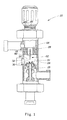
- FIG. 1 shows an apparatus 20 for mixing by producing shear and/or cavitation.
- the apparatus 20 comprises: a mixing and/or cavitation chamber 22 which comprises an entrance 24, at least one inlet 26 and an outlet 28; and an element 30 or structure such as an orifice component with an orifice 32 therein.
- the element 30 is located adjacent the entrance 24 of the mixing and/or cavitation chamber 22.
- the apparatus 20 may further comprise a blade 60, such as a knife-like blade, disposed in the mixing and/or cavitation chamber 22 opposite the element 30 with an orifice 32 therein.
- the apparatus 20 can comprise a SONOLATOR® high pressure homogenizer available from Sonic Corp. of Stratford, CT, U.S.A. as shown; or, in other embodiments a Gaulin homogenizer available from Invensys APV, Lake Mills, WI, U.S.A.; a MICROFLUIDIZER® fluid material processor available from Microfluidics Corp. of Newton, MA, U.S.A.; an atomizer; or, any other suitable apparatus.
- SONOLATOR® high pressure homogenizers are described in the U.S. Patent 3,176,964 issued to Cottell, et al. and U.S. Patent 3,926,413 issued to D'Urso .
- the materials described herein can be used for the parts that are subject to wear in any type of high pressure mixing or homogenizing device, including but not limited to the valve and/or disk used in other high pressure homogenizers.
- the element 30 with the orifice 32 therein can be in any suitable configuration.
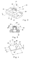
- the element 30 comprises a housing 31 comprising a plate-like portion 34 with a protuberance 36 in the central region of the plate-like portion 34.
- the plate-like portion 34 defines sides or wings 38 to the side of the protuberance 36.
- FIG. 2 shows that the protuberance 36 comprises side walls 40 having a top or front surface 42 joined thereto.
- the front surface 42 of the protuberance 36 has the orifice 32 formed therein and portions 44 surrounding the orifice 32.
- joind encompasses configurations in which an element is directly secured to another element by affixing the element directly to the other element; configurations in which the element is indirectly secured to the other element by affixing the element to intermediate member(s) which in turn are affixed to the other element; and configurations in which one element is integral with another element, i.e., one element is essentially part of the other element.
- the orifice 32 can be in any suitable configuration. Suitable configurations include, but are not limited to: slot-shaped, eye-shaped, elliptically-shaped, triangular, square, rectangular, in the shape of any other polygon, or circular. In some embodiments, as shown in FIG. 2 , it may be desirable for the width of the orifice to exceed the height of the orifice.
- the width of the orifice 32 may be any multiple of the height of the orifice including, but not limited to: 1.1, 1.2, 1.3, 1.4, 1.5, 2, 2.5, 3, 3.5, etc. up to 100 or more times the height of the orifice.
- the orifice 32 can be of any suitable width including, but not limited to, up to about 1 inch (2.54 cm), or more.
- the orifice 32 can have any suitable height including, but not limited to, up to about 0.5 inch (about 1.3 cm), or more.
- FIG. 3 shows that the element 30 with the orifice 32 therein can comprise one or more components or an orifice component system.
- the element 30 with the orifice 32 therein comprises a housing 31 with a hollow protuberance 36, and the hollow protuberance 36 has an insert 46 therein.
- the insert 46 can be in any suitable configuration.
- the insert 46 is a bullet-shaped element that has one or more flange portions 48 at the mid-portion and/or rear part of the insert 46.
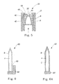
- the insert 46 has an interior passageway for transport of liquid therethrough and a nozzle portion 50 at the front of the insert. This interior passageway is shown in greater detail in FIG. 5.
- FIG. 5 shows that the element 30 with the orifice 32 therein can comprise one or more components or an orifice component system.
- the element 30 with the orifice 32 therein comprises a housing 31 with a hollow protuberance 36, and the hollow protuberance 36 has an insert 46 therein.
- the insert 46 can be in any suitable configuration.
- the insert 46 is
- the portions 44 surrounding the orifice 32 form a wall 52 that becomes thinner in at least some places as the orifice 32 is approached.
- Numerous other configurations for the insert 46 are possible including, but not limited to flat, plate-like configurations.
- the insert 46 may be made of a harder material than other portions or components of the structure comprising the element 30.
- the insert 46 is used so that the other larger portions or components of the element 30 can be made from a less hard, and less expensive material.
- the element 30, and the components thereof, can be made of any suitable material or materials.
- suitable materials include, but are not limited to: titanium, stainless steel, tool steel, cemented tungsten carbide, ceramics (including oxide ceramic materials and non-oxide ceramic materials), silicon nitride (Si 3 N 4 ), titanium nitride (TiN), aluminum oxide (Al 2 O 3 ) (which in single crystal form is known as sapphire), silicon carbide (SiC), titanium carbide (TiC), boron carbide (B 4 C), titanium diboride (TiB 2 ), boron oxide (B 6 O), cubic boron nitride (cBN) (including polycrystalline cBN and epitaxially-grown cBN), cubic BC 2 N, diamond-like carbon (DLC), diamond (e.g., bulk diamond) (natural and synthetic), composites of diamond and/or cubic boron nitride, and coatings of any of the above materials, including but not limited to diamond-coated materials (poly
- suitable materials include combinations of incompressible transition metals, which are relatively soft (such as osmium, rhenium, and ruthenium), with small covalent main group elements having short bonds (such as boron, carbon, nitrogen, or oxygen) to make the metals hard, producing materials such as osmium diboride (OsB 2 ), rhenium diboride (ReB 2 ) and ruthenium diboride (RuB 2 ).
- incompressible transition metals which are relatively soft (such as osmium, rhenium, and ruthenium), with small covalent main group elements having short bonds (such as boron, carbon, nitrogen, or oxygen) to make the metals hard, producing materials such as osmium diboride (OsB 2 ), rhenium diboride (ReB 2 ) and ruthenium diboride (RuB 2 ).
- osmium carbide OsC
- osmium nitride OsN
- osmium dioxide OsO 2
- rhenium carbide ReC
- rhenium nitride ReN
- rhenium dioxide ReO 2
- RuC ruthenium carbide
- RuN ruthenium nitride
- RuO 2 ruthenium dioxide
- the Vickers hardness H v of several of these materials are provided in Table 1 below. According to J. Mater, Res., Vol. 17, No. 12, December 2002, Materials Research Society , materials with a Vickers hardness greater than or equal to 40 GPa are considered to be superhard materials. Table 1.
- the element 30 comprises a housing 31 and an insert 46.
- at least the nozzle portion 50 at the front of the insert 46 may be made of a material having a Vickers hardness of greater than or equal to about 20 GPa because this is the portion of the orifice component system that is subject to the greatest forces when liquids and/or other material is sprayed through the nozzle portion 50.
- the entire insert 46 may be made of a material having a hardness in the hardness ranges specified above.
- At least the portions 44 surrounding the orifice 32 may be made of a material having a hardness in the hardness ranges specified above.
- the element 30, and the components thereof, can be formed in any suitable manner. Any of the components of the orifice component system 30 can be formed from solid pieces of the materials described above which are available in bulk form. The components may also be formed of a solid piece of one of the materials specified above, which is coated over at least a portion of its surface with one or more different materials specified above. In these embodiments, or in other embodiments, the orifice component system 30 can be formed from more than one piece. In this latter case, the different pieces can be formed from different materials.
- the orifice 32 can be provided in an insert, such as insert 46, that is cut out of a diamond using a laser or hot wire diamond cutter, diamond-based cutting tools, and optionally polished using diamond dust. This insert 46 can be inserted into or joined to a metal piece that forms the rest of the orifice component system, such as the housing 31. In other cases, the entire element 30, including the housing 31 can be made of bulk diamond, and there need not be an insert.
- the apparatus for mixing by producing shear and/or cavitation may comprise a blade 60.
- a blade 60 may be used, for example, if it is desired to use the apparatus 20 to form emulsions with a lower mean droplet size than if the blade was not present.
- the blade 60 has a front portion 62 comprising a leading edge 64, and a rear portion 66 comprising a trailing edge 68.
- the blade 60 also has an upper surface 70, a lower surface 72, and a thickness, h, measured between the upper and lower surfaces.
- the blade 60 has a pair of side edges 74 and a width, b, measured between the side edges 74.
- the blade 60 can have any suitable configuration. As shown in FIG. 4 , the blade can comprise a tapered portion 76 in which the thickness of the blade increases from the leading edge 64 in a direction from the leading edge 64 toward the trailing edge 68 along a portion of the distance between the leading edge 64 and the trailing edge 68.
- the blade 60 shown in FIG. 4 has a single tapered or sharpened edge forming its leading edge 64.
- the blade 60 may have two, three, or four or more tapered or sharpened edges.
- the blade 60 can have a rectangular, or square configuration, and any or all of its sides can be sharpened. Such a configuration may be useful so that the blade 60 can be inserted into the apparatus 20 with any of the sharpened edges oriented to form the leading edge 64 of the blade 60. This will multiply the useful life of the blade before it is necessary to repair the same.
- the blade 60 can have any suitable dimensions. In certain embodiments, the blade 60 can range in size from as small as 1mm long and 7 microns thick to as big as 50 cm long and over 100 mm thick. One non-limiting example of a small blade is about 5 mm long and 0.2 mm thick. A non-limiting example of a larger blade is 100 mm long and 100 mm thick.
- the blade 60 when the blade 60 is inserted into the apparatus 20, a portion of the rear portion of the blade 60 is clamped, or otherwise joined inside the apparatus so that its position is fixed.
- the blade 60 can be configured in any suitable manner so that it can be joined to the inside of the apparatus.
- the rear portion 66 of the blade 60 has at least one hole 78 therein for receiving a structure that passes through the hole. This hole and structure serves as at least part of the mechanism used to retain the blade 60 in place inside the apparatus 20.
- the blade 60 can also be joined to a holder which may be comprised of metal or another suitable material. The remainder of the blade 60, including the front portion 62 of the blade 60, is free and is cantilevered relative to the fixed portion.
- the blade 60 can comprise any suitable material or materials.
- the blade desirably will comprise a material, or materials, that are chemically compatible with the fluids to be processed. (The same may also be desirable for the components of the orifice component system.) It may be desirable for the blade to be comprised at least partially of a material that is chemically resistant to one or more of the following conditions: low pH's (pH's below about 5); high pH's (pH's above about 9); salts (chloride ions); and oxidation.
- Suitable materials for the blade 60 include, but are not limited to any material or materials described herein as being suitable for use in the orifice component system, and the components thereof. It should be understood, however, that the materials specified herein do not necessarily have all of the desired chemical resistance properties. The entire blade 60 may be comprised of one of the above materials.
- a portion of the blade 60 may comprise one of the materials described herein as being suitable for use in the orifice component system, and another portion (or portions) of the blade 60 may comprise a different one of these materials.
- a portion of the blade such as the tapered portion 76
- the remainder of the blade 60 can be comprised of some other material, such as a material that has one or more of the following properties: is less hard, less expensive, more ductile, or less brittle than the tapered portion 76.
- Table 2 shows non-limiting examples of many of the different possible combinations of materials that can be used to construct one or more components of an element 30, or a composite blade 60.
- the letter “A” in Table 2 represents a portion of one or more components of the element 30, or a composite blade 60 structure shown in FIGS. 5 and 6 , respectively, that may be referred to as an "inner” portion or structure, and the letter “B” represents a component of the composite structure that may be referred to as an "outer” portion or coating.
- the inner portion A of the blade 60 could comprise sintered PCD which has a diamond coating, B, formed by chemical vapor deposition.
- the apparatus 20 may further be desirable for the apparatus 20 to be provided with dampening material 80 between the blade 60 and the structure 82 to which the blade 60 is clamped.
- Material suitable for dampening includes, but is not limited to rubber, TEFLON® material, and indium foil.
- the blade 60 shown in FIG. 6A has a coating B thereon, and additionally has a second coating, C, disposed on the coating B.
- the coating B forms an intermediate coating.
- the coatings B and C can both comprise the same material; or, they may comprise any different materials described herein as being suitable for application in the form of coatings. Such additional coatings can be provided for any suitable purpose.
- the coating C has the hardness desired, but it is not chemically or thermally compatible with the material forming the inner portion A, it may be desirable to form an intermediate coating B that is compatible with the material forming the inner portion A and the material of coating C so that coating C can be properly joined to the inner portion A.
- any of the structures described herein can be repaired with any of the coatings described herein.
- a component of the orifice component system 30 or the blade 60 degrades through wear, it is possible to repair the worn component or blade with the coatings described herein (such as repairing the same with a diamond coating formed by chemical vapor deposition).
- Table 2 Table 2.
- the blade 60 may have any suitable hardness.
- at least the tapered portion 76 of the blade 60 is formed from a material with a hardness in the hardness ranges specified above.
- at least the tapered portion 76 of the blade 60 may be formed from a material with a Vickers hardness in any increment of 1 Vickers hardness unit above 20 GPa.
- the remainder of the blade can comprise a material that has a Vickers hardness of less than 20 GPa.
- the tapered portion 76 of the blade 60 can be provided with a diamond coating, and the remainder of the blade 60 could be made of stainless steel.
- a blade 60 Several non-limiting examples of methods of forming a blade 60 are described below. These include: forming a coated composite structure; forming a blade by coating layers of a material to form or build the final blade structure; and, forming a blade of a bulk material. The same techniques can be used to form components of the orifice component system, or components of other types of devices.
- coated composite structures such as diamond coated structures, cBN coated structures, diamond composite coated structures, or structures coated with any of the other materials described herein which are capable of being applied in the form of coatings. Suitable methods include, but are not limited to: physical vapor deposition, chemical vapor deposition, and plasma deposition.
- a composite blade is formed from a stainless steel, titanium, or cemented tungsten carbide substrate that forms the interior of the blade, which is coated with a diamond coating, cBN, or diamond like carbon coating.
- a polycrystalline solid diamond blade 60 is made by coating a generally flat silicon single crystal substrate or wafer with diamond using plasma by conventional plasma deposition techniques, such as plasma chemical vapor deposition (CVD), or by hot filament deposition.
- CVD plasma chemical vapor deposition
- the silicon substrate is initially seeded with small (approximately 1 micron in size) diamond nuclei by rubbing diamond paste or diamond powder onto the substrate.
- the diamond-coating approach can use saturated or non-saturated hydrocarbons, such as methane, acetylene, or ethylene in a hydrogen or in a noble gas (such as argon) environment and/or plasma environment to deposit the diamond-containing coating.
- the diamond-containing coating can be deposited layer-by-layer on the silicon substrate.
- the process is discontinued, and the silicon substrate can be removed.
- This process may be referred to as plasma-enhanced chemical vapor deposition (or "PECVD").
- PECVD plasma-enhanced chemical vapor deposition
- the silicon substrate can be removed by (wet or dry) etching, or by mechanical grinding. This will create a blade structure which is rough on both sides.
- the blade can be provided with a tapered leading edge by laser ablation and/or mechanical grinding. Chemical and/or mechanical means can then be used to polish the blade structure.
- the blade 60 can comprise a bulk material, such as bulk diamond material.
- a bulk material such as bulk diamond material.
- Such a material can be formed in any suitable manner such as by high pressure and high temperature sintering in the presence of bonding elements such as cobalt, nickel, or iron using presses that form synthetic diamond from diamond dust. Forming the blade out of some materials, such as bulk diamond may be useful to provide the blade with more efficient acoustic vibration characteristics.
- the acoustic properties may vary significantly from one material to another. Accordingly, the shape and size of the blade may need to differ depending on the material of the blade for a given resonant mode.
- Cavitation threshold (the minimum acoustic pressure at the onset of cavitation) is acoustic frequency dependent. At high ultrasonic frequencies, cavitation becomes increasingly more difficult. The maximum cavitation intensity occurs at low ultrasonic frequencies. It is desired to have the blade designed so that its resonant frequency is in the acoustic and low ultrasonic frequency range of from about 15kHz to 100kHz, or any narrower range of frequencies falling within such range including, but not limited to from about 18kHz to 40kHz.
- the blade 60 is schematically illustrated as a rectangular plate in FIG. 4 . Assuming (for simplicity) that the hole is not present, and one end 68 of the blade is clamped, and the other three sides are free.
- the plate has a length of a (from the clamping point), width of b and thickness of h .
- f ij is the resonant frequency at mode indices (i,j), i being the mode number in length, j being the mode number in width
- k ij is a dimensionless frequency parameter
- E is the modulus of elasticity
- ⁇ is the density
- ⁇ Poisson's ratio.
- diamond Due to its high elastic modulus (>900 MPa) and relatively low bulk density (3.512 g/cm 3 ), diamond has the fastest acoustic velocity at 18,024 m/s. This compares to titanium 6,070 m/s, stainless steel of 5,900 m/s, water of 1,500 m/s and air of 310 m/s.
- the blade 60 may be desirable for the blade 60 to have an elastic modulus of greater than or equal to about 700, 750, 800, 850, or 900 GPa. It may be desirable for the blade to have a density of less than or equal to about any of the following: 12, 10, 9, 8, 7, 6, 5, 4, or 3.6 g/cm 3 . It may be desirable for the blade 60 to have or be made from a material having a predicted acoustic velocity greater than or equal to about any of the following: 7,640, 8,000, 9,000, 10,000, 11,000, 12,000, 13,000, 14,000, 15,000, or 16,000 m/s.
- FIG. 7 shows the frequency of a blade made of bulk diamond as a function of blade thickness and length.
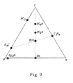
- FIG. 8 unlike blades made from other materials, in the case of blades made from certain superhard materials (particularly those having low densities like diamond), the aspect ratio (ratio of blade length to blade width) has been found to have little impact on the resonant mode. In other words, the blade can be made narrow or wide, with little impact on the resonant frequency. This enables the blade to be made relatively wide without changing the length of the blade. This can provide the advantage of allowing increased flow rates to be handled by the apparatus by merely increasing the widths of the orifice and the blade, without changing the length, or thickness of the blade.
- a process for producing a stable composition according to claim 1 is contemplated herein.
- the process utilizes an apparatus 20 such as that described above.
- the process comprises providing a mixing or cavitation chamber, such as 22, and an element 30, such as orifice component system, with an orifice 32 therein.
- the element 30 comprises portions 44 surrounding the orifice 32, and the portions 44 surrounding the orifice 32 may be provided with a hardness in the hardness ranges specified above.
- the process further comprises introducing at least one fluid into at least one entrance to the mixing or cavitation chamber 22 so that the fluid passes through the orifice 32 in the element 30.
- the at least one fluid can be supplied to the apparatus 20 in any suitable manner including, but not limited to through the use of pumps and motors powering the same.
- the pumps can supply at least one fluid to the apparatus under the desired pressure.
- the fluid(s), or the mixture of the fluids pass through the orifice 32 under pressure.
- the orifice 32 is configured, either alone, or in combination with some other component, to mix the fluids and/or produce cavitation in the fluid(s), or the mixture of the fluids.
- the fluid can comprise any suitable liquid or gas.
- the different phases can comprise one or more liquid, gas, or solid phases.
- Suitable liquids include, but are not limited to: water, oil, solvents, liquefied gases, slurries, and melted materials that are ordinarily solids at room temperature.
- Melted solid materials include, but are not limited to waxes, organic materials, inorganic materials, polymers, fatty alcohols, and fatty acids.
- the fluid(s) can also have solid particles therein.
- the particles can comprise any suitable material including, but not limited to: TiO 2 , bismuth containing materials, ZnO, CaCO 3 , Na 2 SO 4 , and Na 2 CO 3 .
- the particles can be of any suitable size, including macroscopic particles and nanoparticles. In some cases, at least some of these solid particles may be amorphous. In some cases, at least some of these solid particles may be crystalline. In some cases, at least some of the solid particles may be abrasive.
- These particles may be present in any suitable amount in the liquid. Suitable amounts may fall within any suitable range, including but not limited to between about 0.01% to about 40% or more; alternatively between about 0.1% to about 10%; or, alternatively between about 0.5% and about 4% by weight.
- the process may further comprise providing a vibratable blade, such as blade 60, disposed in the mixing or cavitation chamber 22 opposite the element 30 with an orifice 32 therein.
- the blade 60 may be provided with a hardness in the hardness ranges specified above.
- the process may include a step of forming the liquid into a jet stream and impinging the jet stream against the vibratable blade with sufficient force to induce the blade to vibrate harmonically at an intensity that is sufficient to generate cavitation in the fluid.
- the cavitation may be hydrodynamic, acoustic, or ultrasonic.
- the blade 60 undergoes harmonic ultrasonic vibration at a frequency of from about 15kHz to about 100kHz.
- the process may be carried out under any suitable pressure.
- the pressure as measured at the feed to the orifice immediately prior to the point where the fluid passes through the orifice is greater than or equal to about 500 psi. (about 3.4 x 10 6 Pascals), or any number greater than 500 psi. including, but not limited to: 1,000, 1,500, 2,000, 2,500, 3,000, 3,500, 4,000, 4,500, 5,000, 5,500, 6,000, 6,500, 7,000, 7,500, 8,000, 8,500, 9,000, 9,500, 10,000 psi., and any 500 psi. increment above 10,000 psi., including 15,000, 20,000, or higher.
- a given volume of fluid can have any suitable residence time within the cavitation chamber. Some suitable residence times include, but are not limited to from about 1 millisecond to about 1 second, or more.
- the fluid(s) can flow at any suitable flow rate through the cavitation chamber. Suitable flow rates range from about 1 to about 1,000 L/minute, or more, or any narrower range of flow rates falling within such range including, but not limited to from about 5 to about 1,000 L/min.
- the process may also be run continuously for any suitable period of time, with reduced wear on the element 30 with the orifice therein, and on the blade 60. Suitable times include, but are not limited to greater than or equal to about: 30 minutes, 45 minutes, 1 hour, and any increment of 30 minutes above 1 hour.
- a process for using a SONOLATOR® with at least one of the components described herein may be used to produce a stable composition comprising an inorganic aggregate.
- a composition may, for example, comprise an improved version of a bismuth-containing liquid pharmaceutical composition.
- Bismuth-containing liquid pharmaceutical compositions are described in U.S. Patent 4,940,695 issued to Coveney, et al. and U.S. Patent 5,013,560 issued to Stentz, et al.
- a well-known example of such a composition is PEPTO-BISMOL® sold by The Procter & Gamble Company.
- Such a bismuth-containing liquid pharmaceutical composition may comprise several components. These include: a bismuth-containing pharmaceutical agent; a suspension system capable of suspending the bismuth-containing pharmaceutical agent and other components in an aqueous media; water; preservatives such as benzoic acid and sorbic acid; and optional ingredients.
- the bismuth-containing pharmaceutical agent may be in the form of a pharmaceutically-acceptable salt.
- Suitable bismuth-containing pharmaceutical agents include, for example, bismuth aluminate, bismuth subcarbonate, bismuth subcitrate, bismuth citrate, tripotassium dicitrato bismuthate, bismuth galate, bismuth subgalate, bismuth subnitrate, bismuth tartrate, bismuth subsalicylate, and mixtures thereof.
- Bismuth citrate and bismuth galate are soluble in water, and do not need to be deaggregated.
- Such pharmaceutical compositions typically comprise, by weight, from about 0.1% to about 5%, alternatively from about from about 0.5% to about 5%, from about 1% to about 4%, or from about 1.6% to about 1.9% of a bismuth-containing pharmaceutical agent.
- the suspension systems include clay-based and cellulosic suspending agents which may comprise a pharmaceutically-acceptable non-ionic cellulose ether polymer, magnesium aluminum silicate, or mixtures thereof.
- Suitable cellulosic suspending agents such as non-ionic cellulose ether polymers are selected from the group consisting of alkylcelluloses (e.g., methylcellulose), hydroxyalkylalkylcelluloses (e.g., hydroxypropylmethylcellulose: hydroxybutylmethylcellulose; hydroxyethylmethylcellulose; ethylhydroxyethylcellulose), hydroxyalkylcelluloses (e.g., hydroxyethylcellulose; hydroxypropylcellulose), and mixtures thereof.
- alkylcelluloses e.g., methylcellulose
- hydroxyalkylalkylcelluloses e.g., hydroxypropylmethylcellulose: hydroxybutylmethylcellulose; hydroxyethylmethylcellulose; ethylhydroxyethylcellulose
- compositions typically comprise, by weight, from 0.1% to 5%, alternatively from 0.1% to 3%, from 0.5% to 1.5%, or from 0.8% to 1.2%, of a non-ionic cellulose ethyl polymer.
- the suspension system of the compositions described herein also includes clay-based agents and may comprise a magnesium aluminum silicate, kaolin, and combinations thereof.
- Magnesium aluminum silicate (or aluminum magnesium silicate) has the formula Al 2 MgO 8 Si 2 , and occurs naturally in such smectite minerals as colerainite, saponite, and sapphirine.
- Refined magnesium aluminum silicates useful herein are readily available, such as VEEGUM® magnesium aluminum silicate manufactured by R. T. Vanderbilt Company, Inc.
- the pharmaceutical compositions typically comprise, by weight, from 0.1% to 5%, alternatively from 0.1 % to 3%, from 0.5% to 1.5%, or from 0.8% to 1.2%, of a magnesium aluminum silicate.
- the suspension systems for the compositions described herein typically comprise from 0.1% to 10%, alternatively from 0.5% to 5%, or from 1% to 3%, by weight of the composition.
- liquid compositions described herein further comprise from 80% to 99%, alternatively from 90% to 99%, or from 93% to 98% water.
- compositions may comprise preservatives such as benzoic acid and sorbic acid.
- the composition may comprise from 0.01% to 0.075%, alternatively from 0.01% to 0.06%, or from 0.025% to 0.05%, of benzoic acid.
- the composition may comprise from 0.01% to 0.04%, alternatively from 0.01% to 0.03%, or from 0.0125% to 0.025%, of sorbic acid.
- the weight percent ranges of these preservative components are by weight of the protonated species, whether or not all of the acids are in the protonated form in the composition.
- compositions may comprise additional optional components selected as appropriate for the particular composition being prepared.
- the choice of pharmaceutically-acceptable optional components to be used in the compositions is basically determined by the properties, especially aesthetic properties, desired for the composition.
- substances which can serve as pharmaceutically-acceptable optional components are sugars such as lactose, glucose and sucrose; non-nutritive sweeteners such as saccharin, aspartame, acesulfame, and cyclamate; coloring agents; flavoring agents such as methyl salicylate; etc.
- a preferred optional component is salicylic acid which may be used to reduce pH and/or provide some preservative benefit.
- Other compatible pharmaceutical additives and actives e.g., NSAI drugs; H 2 receptor blocking anti-secretory agents
- PEPTO BISMOL® liquid can be made by preparing separate intermediates of magnesium aluminum silicate (such as VEEGUM®), methylcellulose (“methocel”), and bismuth subsalicylate (“BSS”) in water. These intermediates can be sent separately through the SONOLATOR® where the desired transfomations, such as dispersion, hydration and de-aggregation are performed on them.
- the processes of interest herein may include fewer than all of these transformations, and may, but need not, include all of the steps described below.
- the intermediates can be formed in any order. In addition, any one or more of the steps described below may be combined.
- Such a process may provide a number of benefits. It should be understood, however, that obtaining such benefits is not required unless specified in the appended claims.
- One benefit is the ability to provide a narrower particle size distribution and a smaller average particle size of the bismuth-containing pharmaceutical agent in a single pass through the SONOLATOR® than is possible unless using many passes through other types of mixing devices such as high shear mixers. Smaller sized particles are useful in providing a more stable composition, which is less susceptible to having the ingredients settle out. Smaller sized particles of the bismuth-containing pharmaceutical agent also allow reduced quantities of suspending agents to be used. For example, the amount of the ingredients marked with the asterisk in the table below may be about 10% lower than that required in prior processes which use high shear mixers.
- transformations may be more efficient in that they may progress further toward their completion than when other types of mixing devices are used.
- components described herein may be sufficiently durable to allow the apparatuses to be used to make large scale quantities of the compositions of interest.
- the process described herein may also be capable of being carried out over a shorter time period (e.g., in approximately half the time) as processes which use other types of mixing devices, making it a more efficient and economical process.
Landscapes
- Chemical & Material Sciences (AREA)
- Chemical Kinetics & Catalysis (AREA)
- Health & Medical Sciences (AREA)
- Dispersion Chemistry (AREA)
- General Health & Medical Sciences (AREA)
- Epidemiology (AREA)
- Life Sciences & Earth Sciences (AREA)
- Animal Behavior & Ethology (AREA)
- Pharmacology & Pharmacy (AREA)
- Public Health (AREA)
- Veterinary Medicine (AREA)
- Medicinal Chemistry (AREA)
- Toxicology (AREA)
- Inorganic Chemistry (AREA)
- Mixers Of The Rotary Stirring Type (AREA)
- Colloid Chemistry (AREA)
Claims (12)
- Verfahren zum Herstellen einer stabilen Zusammensetzung, umfassend die folgenden Schritte:a. Herstellen, durch hydrodynamische Kavitation, einer ersten Zwischenzusammensetzung, die ein tonbasiertes Suspendiermittel und Wasser umfasst,b. Herstellen, durch hydrodynamische Kavitation, einer zweiten Zwischenzusammensetzung, die ein cellulosisches Suspendiermittel und Wasser umfasst,c. Herstellen, durch hydrodynamische Kavitation, einer dritten Zwischenzusammensetzung, die ein anorganisches Aggregat und Wasser umfasst, undd. Mischen der ersten, der zweiten und der dritten Zwischenzusammensetzung miteinander, um eine stabile Zusammensetzung zu bilden.
- Verfahren nach Anspruch 1, wobei das tonbasierte Suspendiermittel ausgewählt ist aus der Gruppe bestehend aus: einem Magnesiumaluminiumsilikat, Kaolin und Kombinationen davon, vorzugsweise Magnesiumaluminiumsilikat.
- Verfahren nach Anspruch 2, wobei das tonbasierte Suspendiermittel in einer Menge von 0,1 Gew.-% bis 5 Gew.-% der stabilen Zusammensetzung vorhanden ist.
- Verfahren nach Anspruch 1, wobei das cellulosische Suspendiermittel ein nichtionisches Celluloseetherpolymer ist.
- Verfahren nach Anspruch 1, wobei das cellulosische Suspendiermittel ausgewählt ist aus der Gruppe bestehend aus: Alkylcellulosen, Hydroxylalkylalkylcellulosen, Hydroxyalkylcellulosen und Mischungen davon, vorzugsweise Methylcellulose.
- Verfahren nach Anspruch 4 oder 5, wobei das cellulosische Suspendiermittel in einer Menge von 0,1 Gew.-% bis 5 Gew.-% der stabilen Zusammensetzung vorhanden ist.
- Verfahren nach Anspruch 1, wobei das anorganische Aggregat ein bismuthaltiges Arzneimittel ist, das vorzugsweise ausgewählt ist aus der Gruppe bestehend aus: Bismuthaluminat, Bismutsubcarbonat, Bismutsubcitrat, Trikaliumdicitratobismutat, Bismutsubsalicylat, Bismuttartrat, Bismutsubgalat, Bismutsubnitrat und Mischungen davon.
- Verfahren nach Anspruch 1, wobei das anorganische Aggregat Bismutsubsalicylat ist.
- Verfahren nach Anspruch 7 oder 8, wobei das anorganische Aggregat in einer Menge von 0,1 Gew.-% bis 5Gew.-% der stabilen Zusammensetzung vorhanden ist.
- Verfahren nach Anspruch 1, wobei Schritt a) es Herstellens einer ersten Zwischenzusammensetzung, die ein tonbasiertes Suspendiermittel und Wasser umfasst, die folgenden Schritte umfasst:1) Zugeben einer Wassermenge in einen Behälter mit einem Rührwerk,2) Beladen eines Mischers mit einer Menge eines tonbasierten Suspendiermittels,3) Mischen des tonbasierten Suspendiermittels mit Wasser mithilfe des Mischers, sodass eine Mischung von tonbasiertem Suspendiermittel/ Wasser resultiert,4) Pumpen der Mischung von tonbasiertem Suspendiermittel/Wasser in eine die hydrodynamische Kavitation induzierende Vorrichtung (20) bei einem Wassersäulendruck,5) Pressen der Mischung von tonbasiertem Suspendiermittel/Wasser durch die die hydrodynamische Kavitation induzierenden Vorrichtung bei hohem Druck,6) Induzieren der hydrodynamischen Kavitation in der Mischung von tonbasiertem Suspendiermittel/Wasser innerhalb der die hydrodynamische Kavitation induzierenden Vorrichtung,7) Dispergieren und Hydratisieren des tonbasierten Suspendiermittels durch die hydrodynamische Kavitation,8) Entfernen der Mischung von tonbasiertem Suspendiermittel/Wasser aus der die hydrodynamische Kavitation induzierender Vorrichtung (20) und Anlagern der Mischung von tonbasiertem Suspendiermittel/ Wasser in einem Endbehälter und9) Zugeben einer Menge abgekühlten Wassers zu der Mischung von tonbasiertem Suspendiermittel/Wasser in den Endbehälter.
- Verfahren nach Anspruch 1, wobei Schritt b) des Herstellens einer zweiten Zwischenzusammensetzung, die ein cellulosisches Suspendiermittel und Wasser umfasst, die folgenden Schritte umfasst:1) Zugeben einer Menge erwärmten Wassers in einen Behälter mit einem Rührwerk,2) Beladen eines Mischers mit einer Menge eines cellulosischen Suspendiermittels,3) Mischen des cellulosischen Suspendiermittels mit Wasser mithilfe des Mischers, sodass eine Mischung von cellulosischem Suspendiermittel/ Wasser resultiert,4) Pumpen der Mischung von cellulosischem Suspendiermittel/Wasser in eine die hydrodynamische Kaviation induzierende Vorrichtung (20) bei einem Wassersäulendruck,5) Pressen der Mischung von cellulosische Suspendiermittel/Wasser durch die die hydrodynamische Kavitation induzierende Vorrichtung bei hohem Druck,6) Induzieren der hydrodynamischen Kavitation in der Mischung von cellulosischem Suspendiermittel/Wasser innerhalb der die hydrodynamische Kavitation induzierenden Vorrichtung,7) Dispergieren des cellulosischen Suspendiermittels durch die hydrodynamische Kavitation,8) Entfernen der Mischung von cellulosischem Suspendiermittel/Wasser aus der die hydrodynamische Kavitation induzierenden Vorrichtung (20) und Anlagern der Mischung von cellulosischem Suspendiermittel/Wasser in dem Endbehälter, und9) Zugeben einer Menge abgekühlten Wassers in den Endbehälter.
- Verfahren nach Anspruch 1, wobei Schritt c) des Herstellens einer dritten Zwischenzusammensetzung, die ein anorganisches Aggregat und Wasser umfasst, die folgenden Schritte umfasst:1) Zugeben einer Wassermenge in einen Behälter mit einem Rührwerk,2) Beladen eines Mischers mit einer Menge eines anorganischen Aggregats,3) Mischen des anorganischen Aggregats mit dem Wasser mithilfe des Mischers, sodass eine Mischung von anorganischem Aggregat/Wasser resultiert,4) Pumpen der Mischung von anorganischem Aggregat/Wasser in eine die hydrodynamische Kaviation induzierenden Vorrichtung (20) bei einem Wassersäulendruck,5) Pressen der Mischung von anorganischem Aggregat/Wasser durch die die hydrodynamische Kavitation induzierenden Vorrichtung bei hohem Druck,6) Induzieren der hydrodynamischen Kavitation in der Mischung von anorganischem Aggregat/Wasser innerhalb der die hydrodynamische Kavitation induzierenden Vorrichtung,7) Deaggregieren des anorganischen Aggregats durch die hydrodynamische Kavitation und8) Entfernen der Mischung von anorganischem Aggregat/Wasser von der die hydrodynamische Kavitation induzierenden Vorrichtung (20) und Anlagern der Mischung von anorganischem Aggregat/Wasser in dem Endbehälter unter Rühren.
Applications Claiming Priority (2)
| Application Number | Priority Date | Filing Date | Title |
|---|---|---|---|
| US93750107P | 2007-06-28 | 2007-06-28 | |
| EP08789163A EP2158028B1 (de) | 2007-06-28 | 2008-06-27 | Vorrichtung und verfahren zum mischen durch erzeugen von scherung und kavitation in einer flüssigkeit |
Related Parent Applications (1)
| Application Number | Title | Priority Date | Filing Date |
|---|---|---|---|
| EP08789163A Division EP2158028B1 (de) | 2007-06-28 | 2008-06-27 | Vorrichtung und verfahren zum mischen durch erzeugen von scherung und kavitation in einer flüssigkeit |
Publications (3)
| Publication Number | Publication Date |
|---|---|
| EP2389999A2 EP2389999A2 (de) | 2011-11-30 |
| EP2389999A3 EP2389999A3 (de) | 2012-02-22 |
| EP2389999B1 true EP2389999B1 (de) | 2013-01-09 |
Family
ID=40056202
Family Applications (2)
| Application Number | Title | Priority Date | Filing Date |
|---|---|---|---|
| EP11178631A Not-in-force EP2389999B1 (de) | 2007-06-28 | 2008-06-27 | Mischverfahren zur Herstellung einer stabilen Mischung |
| EP08789163A Not-in-force EP2158028B1 (de) | 2007-06-28 | 2008-06-27 | Vorrichtung und verfahren zum mischen durch erzeugen von scherung und kavitation in einer flüssigkeit |
Family Applications After (1)
| Application Number | Title | Priority Date | Filing Date |
|---|---|---|---|
| EP08789163A Not-in-force EP2158028B1 (de) | 2007-06-28 | 2008-06-27 | Vorrichtung und verfahren zum mischen durch erzeugen von scherung und kavitation in einer flüssigkeit |
Country Status (8)
| Country | Link |
|---|---|
| US (1) | US8517595B2 (de) |
| EP (2) | EP2389999B1 (de) |
| KR (1) | KR20100008373A (de) |
| CN (1) | CN101687153A (de) |
| CA (2) | CA2794102C (de) |
| ES (1) | ES2399471T3 (de) |
| PL (1) | PL2158028T3 (de) |
| WO (1) | WO2009001323A2 (de) |
Families Citing this family (32)
| Publication number | Priority date | Publication date | Assignee | Title |
|---|---|---|---|---|
| KR20100008373A (ko) * | 2007-06-28 | 2010-01-25 | 더 프록터 앤드 갬블 캄파니 | 전단 및/또는 캐비테이션 생성에 의한 유체의 혼합을 위한 장치 및 방법, 및 그러한 장치를 위한 구성요소 |
| US8431102B2 (en) * | 2008-04-16 | 2013-04-30 | The Regents Of The University Of California | Rhenium boride compounds and uses thereof |
| US8322910B2 (en) * | 2008-07-25 | 2012-12-04 | The Procter & Gamble Company | Apparatus and method for mixing by producing shear and/or cavitation, and components for apparatus |
| EP2228461A1 (de) * | 2009-02-26 | 2010-09-15 | Siemens Aktiengesellschaft | Bauteilbeschichtung |
| EP2551077A1 (de) | 2011-07-26 | 2013-01-30 | A O Schallinox GmbH | Messer zum Aufteilen von Prozessgut unter Anwendung von Ultraschallenergie sowie Vorrichtung |
| US9777349B2 (en) | 2011-10-17 | 2017-10-03 | Sandvik Intellectual Property Ab | Method of making a cemented carbide or cermet body |
| EP2584057B1 (de) * | 2011-10-17 | 2016-08-03 | Sandvik Intellectual Property AB | Verfahren zur Herstellung von zementiertem Karbid oder Cermet-Pulver durch Verwendung eines akustischen Resonanzmischers |
| CN105008034B (zh) * | 2012-12-27 | 2018-10-19 | 应用空化有限公司 | 空化装置及其使用方法 |
| US9185484B2 (en) | 2013-01-16 | 2015-11-10 | Curtis E. Graber | Hydrodynamic modulator |
| US9111520B2 (en) | 2013-03-12 | 2015-08-18 | Curtis E. Graber | Flexural disk transducer shell |
| US9718035B2 (en) | 2013-04-11 | 2017-08-01 | Bunn-O-Matic Corporation | Carbonator system, method and apparatus |
| WO2015087268A2 (en) | 2013-12-12 | 2015-06-18 | Indian Institute Of Technology Madras | Systems and methods for gas hydrate slurry formation |
| US20220111560A9 (en) * | 2014-04-08 | 2022-04-14 | Applied Cavitation, Inc. | Systems and methods for producing materials suitable for additive manufacturing using a hydrodynamic cavitation apparatus |
| WO2015157433A1 (en) * | 2014-04-08 | 2015-10-15 | Applied Cavitation, Inc. | Systems and methods for producing materials suitable for additive manufacturing using a hydrodynamic cavitation apparatus |
| US9486436B2 (en) * | 2014-04-29 | 2016-11-08 | The Procter & Gamble Company | Method for making bismuth containing liquid pharmaceutical suspensions |
| EP2992949A1 (de) | 2014-09-03 | 2016-03-09 | The Procter and Gamble Company | Verfahren zur Herstellung wässriger Emulsionen oder Suspensionen |
| EP2992950A1 (de) | 2014-09-03 | 2016-03-09 | The Procter and Gamble Company | Verfahren zur Herstellung wässriger Emulsionen oder Suspensionen |
| EP3448552B1 (de) * | 2016-04-26 | 2022-06-08 | Basf Se | Verfahren und vorrichtung zur herstellung einer wässrigen polymerlösung |
| GB201609672D0 (en) * | 2016-06-02 | 2016-07-20 | Element Six Uk Ltd | Sintered polycrystalline cubic boron nitride material |
| DE102017219317A1 (de) | 2017-10-27 | 2019-05-02 | Friedrich-Alexander-Universität Erlangen-Nürnberg | Turbinen-, Verdichter-, im 3D-Druck hergestellte- und/oder Motor-Komponente sowie die Verwendung vorgefertigter Teilstücke zur Oberflächenbeschichtung |
| CN109879249B (zh) * | 2019-04-10 | 2020-01-17 | 广东广牧动物保健品有限公司 | 纳米材料制备系统及其制备方法 |
| EP3783056B1 (de) | 2019-08-23 | 2022-05-11 | The Procter & Gamble Company | Recycling von superabsorbierendem polymer mittels hydrothermaler mikrowellenbehandlung |
| US11154839B2 (en) | 2019-08-23 | 2021-10-26 | The Procter & Gamble Company | Recycling of superabsorbent polymer via UV irradiation in flow system |
| EP4017908A1 (de) | 2019-08-23 | 2022-06-29 | The Procter & Gamble Company | Recycling von superabsorbierendem polymer mit einer dehnungsflussvorrichtung |
| CN110902756B (zh) * | 2019-11-22 | 2021-11-23 | 江苏大学 | 一种污水绿色处理装置 |
| US11649336B2 (en) * | 2020-06-16 | 2023-05-16 | The Procter & Gamble Company | Recycling of superabsorbent polymer with an extensional flow device |
| US11746210B2 (en) * | 2020-06-16 | 2023-09-05 | The Procter & Gamble Company | Recycling of superabsorbent polymer with an extensional flow device |
| CN112110876A (zh) * | 2020-09-26 | 2020-12-22 | 安徽金禾实业股份有限公司 | 一种安赛蜜生产中连续磺化环合的方法 |
| US12384900B2 (en) | 2021-02-22 | 2025-08-12 | The Procter & Gamble Company | Recycling of superabsorbent fibers via UV irradiation in flow system |
| US12104021B2 (en) | 2021-02-22 | 2024-10-01 | The Procter & Gamble Company | Recycling of superabsorbent fibers with an extensional flow device |
| US12491548B2 (en) | 2021-02-22 | 2025-12-09 | The Procter & Gamble Company | Recycling of superabsorbent fibers with an extensional flow device |
| US12152112B2 (en) | 2021-02-22 | 2024-11-26 | The Procter & Gamble Company | Degradation of superabsorbent fibers via oxidative degradation |
Family Cites Families (47)
| Publication number | Priority date | Publication date | Assignee | Title |
|---|---|---|---|---|
| USRE25324E (en) * | 1963-01-29 | Apparatus for the mechanical production of acoustic vibrations | ||
| US2713998A (en) * | 1953-05-18 | 1955-07-26 | Eicken Henri | Means for emulsifying sizing and the like products |
| US3176964A (en) * | 1961-01-05 | 1965-04-06 | Sonic Eng Corp | Method and apparatus for producing acoustic vibrations in fluids |
| US3278165A (en) * | 1963-02-25 | 1966-10-11 | Sonic Eng Corp | Method and apparatus for generating acoustic vibrations in flowing fluids |
| US3285579A (en) * | 1963-05-09 | 1966-11-15 | Guerin Robert | Devices for homogenizing a mixture by ultra-sound vibrations |
| US3357683A (en) * | 1965-04-22 | 1967-12-12 | Ekstroems Maskinaffaer Ab | Apparatus for generating vibrations in liquids |
| US3399031A (en) | 1965-08-17 | 1968-08-27 | Sonic Eng Corp | Method of carrying out chemical reactions and product thereof |
| US3408050A (en) * | 1966-01-13 | 1968-10-29 | Sonic Eng Corp | Apparatus for mixing fluids |
| FR1600187A (de) * | 1968-12-31 | 1970-07-20 | ||
| US3687369A (en) * | 1970-10-12 | 1972-08-29 | North American Car Corp | Cleaning apparatus |
| USRE29161E (en) * | 1971-09-03 | 1977-03-29 | Compagnie Francaise De Raffinage | Devices for the generation of ultrasonics and their application to the preparation of emulsions |
| US3975248A (en) * | 1973-05-31 | 1976-08-17 | Chemprobe Corporation | Molecular composite structures |
| US3926413A (en) * | 1975-01-20 | 1975-12-16 | Sonic Corp | Apparatus for producing acoustic vibrations in liquids |
| US4129387A (en) * | 1976-08-11 | 1978-12-12 | Ultrasonics, Ltd. | Apparatus for the homogenization of liquids |
| US4127332A (en) * | 1976-11-19 | 1978-11-28 | Daedalean Associates, Inc. | Homogenizing method and apparatus |
| US4352571A (en) * | 1980-03-20 | 1982-10-05 | Lucas Industries Limited | Apparatus for homogenizing liquids |
| DE3144920A1 (de) * | 1981-11-12 | 1983-05-26 | Krauss-Maffei AG, 8000 München | Mischkopf |
| US4675194A (en) | 1986-03-03 | 1987-06-23 | Reaction Technology, Inc. | Sonic process for converting proteinaceous raw materials in situ into semi-solid food products |
| US4940695A (en) | 1987-12-10 | 1990-07-10 | The Procter & Gamble Company | Bismuth-containing pharmaceutical compositions |
| US5013560A (en) | 1989-03-17 | 1991-05-07 | The Procter & Gamble Company | Microbially-stable bismuth-containing liquid pharmaceutical suspensions |
| US5026167A (en) | 1989-10-19 | 1991-06-25 | Heat Systems Incorporated | Ultrasonic fluid processing system |
| US5143965A (en) * | 1990-12-26 | 1992-09-01 | The Dow Chemical Company | Magnesium hydroxide having fine, plate-like crystalline structure and process therefor |
| CA2035702C (en) * | 1991-02-05 | 1996-10-01 | Mohan Vijay | Ultrasonically generated cavitating or interrupted jet |
| US5695510A (en) * | 1992-02-20 | 1997-12-09 | Hood; Larry L. | Ultrasonic knife |
| DE19542499A1 (de) * | 1995-11-15 | 1997-05-22 | Bayer Ag | Verfahren und Vorrichtung zur Herstellung einer parenteralen Arzneistoffzubereitung |
| US5975750A (en) * | 1996-07-09 | 1999-11-02 | Semp; Bernard A. | Low frequency, low shear in-line mixing |
| US5837272A (en) | 1996-12-13 | 1998-11-17 | Colgate Palmolive Company | Process for forming stable gelled aqueous composition |
| DK173322B1 (da) | 1998-03-02 | 2000-07-24 | Foss Electric As | Homogenisator og homogenisatorhus |
| ES2216423T3 (es) * | 1998-12-07 | 2004-10-16 | Dsm Ip Assets B.V. | Metodo y dispositivo para mezclar o dispersar liquidos. |
| DE19856604A1 (de) * | 1998-12-08 | 2000-06-15 | Basf Ag | Verfahren und Vorrichtung zur Herstellung einer Emulsion |
| US6443610B1 (en) * | 1998-12-23 | 2002-09-03 | B.E.E. International | Processing product components |
| US6375635B1 (en) * | 1999-05-18 | 2002-04-23 | Hydrocision, Inc. | Fluid jet surgical instruments |
| US6290331B1 (en) * | 1999-09-09 | 2001-09-18 | Hewlett-Packard Company | High efficiency orifice plate structure and printhead using the same |
| US20020054995A1 (en) * | 1999-10-06 | 2002-05-09 | Marian Mazurkiewicz | Graphite platelet nanostructures |
| US6318649B1 (en) * | 1999-10-06 | 2001-11-20 | Cornerstone Technologies, Llc | Method of creating ultra-fine particles of materials using a high-pressure mill |
| EP1222957A1 (de) * | 2000-12-22 | 2002-07-17 | Société des Produits Nestlé S.A. | Verfahren und Vorrichtung zur Herstellung einer Oel-in-Wasser Emulsion mit Nahrungsmittelqualität |
| US7100844B2 (en) * | 2002-10-16 | 2006-09-05 | Ultrastrip Systems, Inc. | High impact waterjet nozzle |
| DE20306915U1 (de) | 2003-05-05 | 2003-08-07 | HAAGEN & RINAU Mischtechnik GmbH, 28307 Bremen | Dispergiervorrichtung |
| US20050136123A1 (en) * | 2003-12-19 | 2005-06-23 | Kozyuk Oleg V. | System and method for heat treating a homogenized fluid product |
| US7448792B2 (en) * | 2005-01-18 | 2008-11-11 | Impulse Devices, Inc. | Hydraulic actuated cavitation chamber with integrated fluid rotation system |
| KR20070114373A (ko) * | 2005-03-29 | 2007-12-03 | 후지필름 가부시키가이샤 | 반응방법과 장치, 그리고 그를 이용한 화학물질의 제조방법및 장치 |
| GB0522444D0 (en) * | 2005-11-03 | 2005-12-14 | Miller Donald S | Cutting heads |
| DE102005057333B4 (de) * | 2005-11-28 | 2008-11-20 | Dr. Hielscher Gmbh | Verfahren und Vorrichtungen zur Beschallung von Flüssigkeiten mit Niederfrequenz-Leistungs-Ultraschall |
| KR20100008373A (ko) * | 2007-06-28 | 2010-01-25 | 더 프록터 앤드 갬블 캄파니 | 전단 및/또는 캐비테이션 생성에 의한 유체의 혼합을 위한 장치 및 방법, 및 그러한 장치를 위한 구성요소 |
| US8708550B2 (en) * | 2007-07-06 | 2014-04-29 | M. Technique Co., Ltd. | Fluid processing apparatus and processing method |
| US8980958B2 (en) * | 2007-11-09 | 2015-03-17 | M. Technique Co., Ltd. | Method for producing emulsion and thereby obtained emulsion |
| US8322910B2 (en) * | 2008-07-25 | 2012-12-04 | The Procter & Gamble Company | Apparatus and method for mixing by producing shear and/or cavitation, and components for apparatus |
-
2008
- 2008-06-27 KR KR1020097026007A patent/KR20100008373A/ko not_active Ceased
- 2008-06-27 EP EP11178631A patent/EP2389999B1/de not_active Not-in-force
- 2008-06-27 CN CN200880022475A patent/CN101687153A/zh active Pending
- 2008-06-27 EP EP08789163A patent/EP2158028B1/de not_active Not-in-force
- 2008-06-27 ES ES08789163T patent/ES2399471T3/es active Active
- 2008-06-27 CA CA2794102A patent/CA2794102C/en not_active Expired - Fee Related
- 2008-06-27 US US12/147,629 patent/US8517595B2/en not_active Expired - Fee Related
- 2008-06-27 WO PCT/IB2008/052603 patent/WO2009001323A2/en not_active Ceased
- 2008-06-27 PL PL08789163T patent/PL2158028T3/pl unknown
- 2008-06-27 CA CA2691875A patent/CA2691875C/en not_active Expired - Fee Related
Also Published As
| Publication number | Publication date |
|---|---|
| ES2399471T3 (es) | 2013-04-01 |
| EP2389999A3 (de) | 2012-02-22 |
| WO2009001323A3 (en) | 2009-06-04 |
| PL2158028T3 (pl) | 2013-04-30 |
| EP2158028B1 (de) | 2012-11-14 |
| US20090003123A1 (en) | 2009-01-01 |
| EP2389999A2 (de) | 2011-11-30 |
| CA2691875C (en) | 2012-12-18 |
| CA2691875A1 (en) | 2008-12-31 |
| US8517595B2 (en) | 2013-08-27 |
| WO2009001323A2 (en) | 2008-12-31 |
| KR20100008373A (ko) | 2010-01-25 |
| CA2794102A1 (en) | 2008-12-31 |
| CN101687153A (zh) | 2010-03-31 |
| EP2158028A2 (de) | 2010-03-03 |
| CA2794102C (en) | 2014-08-19 |
Similar Documents
| Publication | Publication Date | Title |
|---|---|---|
| EP2389999B1 (de) | Mischverfahren zur Herstellung einer stabilen Mischung | |
| EP2318128B1 (de) | Vorrichtung und verfahren zum mischen von flüssigkeiten durch erzeugung von scherung, turbulenz und/oder kavitation | |
| KR102229047B1 (ko) | 공진 음향 믹서를 사용함으로써 초경합금 또는 서멧 분말을 제조하는 방법 | |
| US4555872A (en) | High velocity particulate containing fluid jet process | |
| CN100467104C (zh) | 制备分散液的方法和装置 | |
| EP3266744B1 (de) | Vorrichtung und verfahren zur herstellung von graphen durch exfoliation von graphit durch verwendung eines gepulsten oder hohlraumbildenden wasserstrahls | |
| CA2090371A1 (en) | Water jet mixing tubes used in water jet cutting devices and method of preparation thereof | |
| JP5821072B2 (ja) | 流体処理装置及び処理方法 | |
| US10589234B2 (en) | Wet disperser | |
| US20070111642A1 (en) | Apparatus and methods for slurry cleaning of etch chambers | |
| JPH04305279A (ja) | Cvdダイヤモンド被覆超音波プローブチップ | |
| EP3525935B1 (de) | Vorrichtung und verfahren zur massenherstellung von atomar dünnen 2-dimensionalen materialien mit graphen | |
| JP3960484B2 (ja) | 被覆ダイヤモンド焼結体及びその製造法 | |
| TW311108B (en) | The slurry managing system and method for wire saws | |
| Gruverman et al. | Production of Nanostructures Under Ultraturbulent Collision Reaction Conditions-Application to Catalysts, Superconductors, CMP Abrasives, Ceramics, and Other Nanoparticles | |
| JP6462403B2 (ja) | 湿式分散器 | |
| JP2021118994A (ja) | マイクロバブル生成器 | |
| JPWO1995035157A1 (ja) | 乳剤の製法及び乳化機 | |
| PL208325B1 (pl) | Sposób wytwarzania emulsji prostych i wielokrotnych |
Legal Events
| Date | Code | Title | Description |
|---|---|---|---|
| AC | Divisional application: reference to earlier application |
Ref document number: 2158028 Country of ref document: EP Kind code of ref document: P |
|
| AK | Designated contracting states |
Kind code of ref document: A2 Designated state(s): AT BE BG CH CY CZ DE DK EE ES FI FR GB GR HR HU IE IS IT LI LT LU LV MC MT NL NO PL PT RO SE SI SK TR |
|
| PUAI | Public reference made under article 153(3) epc to a published international application that has entered the european phase |
Free format text: ORIGINAL CODE: 0009012 |
|
| PUAL | Search report despatched |
Free format text: ORIGINAL CODE: 0009013 |
|
| AK | Designated contracting states |
Kind code of ref document: A3 Designated state(s): AT BE BG CH CY CZ DE DK EE ES FI FR GB GR HR HU IE IS IT LI LT LU LV MC MT NL NO PL PT RO SE SI SK TR |
|
| RIC1 | Information provided on ipc code assigned before grant |
Ipc: B01F 5/06 20060101ALI20120117BHEP Ipc: B01F 11/02 20060101ALI20120117BHEP Ipc: A61K 31/60 20060101ALI20120117BHEP Ipc: B01F 3/04 20060101AFI20120117BHEP Ipc: B01F 3/08 20060101ALI20120117BHEP Ipc: B01F 3/12 20060101ALI20120117BHEP Ipc: A61K 33/24 20060101ALI20120117BHEP |
|
| 17P | Request for examination filed |
Effective date: 20120425 |
|
| GRAP | Despatch of communication of intention to grant a patent |
Free format text: ORIGINAL CODE: EPIDOSNIGR1 |
|
| GRAS | Grant fee paid |
Free format text: ORIGINAL CODE: EPIDOSNIGR3 |
|
| GRAA | (expected) grant |
Free format text: ORIGINAL CODE: 0009210 |
|
| AC | Divisional application: reference to earlier application |
Ref document number: 2158028 Country of ref document: EP Kind code of ref document: P |
|
| AK | Designated contracting states |
Kind code of ref document: B1 Designated state(s): AT BE BG CH CY CZ DE DK EE ES FI FR GB GR HR HU IE IS IT LI LT LU LV MC MT NL NO PL PT RO SE SI SK TR |
|
| REG | Reference to a national code |
Ref country code: GB Ref legal event code: FG4D |
|
| REG | Reference to a national code |
Ref country code: CH Ref legal event code: EP Ref country code: AT Ref legal event code: REF Ref document number: 592402 Country of ref document: AT Kind code of ref document: T Effective date: 20130115 |
|
| REG | Reference to a national code |
Ref country code: IE Ref legal event code: FG4D |
|
| REG | Reference to a national code |
Ref country code: DE Ref legal event code: R096 Ref document number: 602008021650 Country of ref document: DE Effective date: 20130307 |
|
| PG25 | Lapsed in a contracting state [announced via postgrant information from national office to epo] |
Ref country code: SI Free format text: LAPSE BECAUSE OF FAILURE TO SUBMIT A TRANSLATION OF THE DESCRIPTION OR TO PAY THE FEE WITHIN THE PRESCRIBED TIME-LIMIT Effective date: 20130109 |
|
| REG | Reference to a national code |
Ref country code: NL Ref legal event code: VDEP Effective date: 20130109 |
|
| REG | Reference to a national code |
Ref country code: AT Ref legal event code: MK05 Ref document number: 592402 Country of ref document: AT Kind code of ref document: T Effective date: 20130109 |
|
| REG | Reference to a national code |
Ref country code: LT Ref legal event code: MG4D |
|
| PG25 | Lapsed in a contracting state [announced via postgrant information from national office to epo] |
Ref country code: ES Free format text: LAPSE BECAUSE OF FAILURE TO SUBMIT A TRANSLATION OF THE DESCRIPTION OR TO PAY THE FEE WITHIN THE PRESCRIBED TIME-LIMIT Effective date: 20130420 Ref country code: SE Free format text: LAPSE BECAUSE OF FAILURE TO SUBMIT A TRANSLATION OF THE DESCRIPTION OR TO PAY THE FEE WITHIN THE PRESCRIBED TIME-LIMIT Effective date: 20130109 Ref country code: BG Free format text: LAPSE BECAUSE OF FAILURE TO SUBMIT A TRANSLATION OF THE DESCRIPTION OR TO PAY THE FEE WITHIN THE PRESCRIBED TIME-LIMIT Effective date: 20130409 Ref country code: AT Free format text: LAPSE BECAUSE OF FAILURE TO SUBMIT A TRANSLATION OF THE DESCRIPTION OR TO PAY THE FEE WITHIN THE PRESCRIBED TIME-LIMIT Effective date: 20130109 Ref country code: LT Free format text: LAPSE BECAUSE OF FAILURE TO SUBMIT A TRANSLATION OF THE DESCRIPTION OR TO PAY THE FEE WITHIN THE PRESCRIBED TIME-LIMIT Effective date: 20130109 Ref country code: IS Free format text: LAPSE BECAUSE OF FAILURE TO SUBMIT A TRANSLATION OF THE DESCRIPTION OR TO PAY THE FEE WITHIN THE PRESCRIBED TIME-LIMIT Effective date: 20130509 Ref country code: BE Free format text: LAPSE BECAUSE OF FAILURE TO SUBMIT A TRANSLATION OF THE DESCRIPTION OR TO PAY THE FEE WITHIN THE PRESCRIBED TIME-LIMIT Effective date: 20130109 Ref country code: NO Free format text: LAPSE BECAUSE OF FAILURE TO SUBMIT A TRANSLATION OF THE DESCRIPTION OR TO PAY THE FEE WITHIN THE PRESCRIBED TIME-LIMIT Effective date: 20130409 |
|
| PG25 | Lapsed in a contracting state [announced via postgrant information from national office to epo] |
Ref country code: PT Free format text: LAPSE BECAUSE OF FAILURE TO SUBMIT A TRANSLATION OF THE DESCRIPTION OR TO PAY THE FEE WITHIN THE PRESCRIBED TIME-LIMIT Effective date: 20130509 Ref country code: GR Free format text: LAPSE BECAUSE OF FAILURE TO SUBMIT A TRANSLATION OF THE DESCRIPTION OR TO PAY THE FEE WITHIN THE PRESCRIBED TIME-LIMIT Effective date: 20130410 Ref country code: LV Free format text: LAPSE BECAUSE OF FAILURE TO SUBMIT A TRANSLATION OF THE DESCRIPTION OR TO PAY THE FEE WITHIN THE PRESCRIBED TIME-LIMIT Effective date: 20130109 Ref country code: PL Free format text: LAPSE BECAUSE OF FAILURE TO SUBMIT A TRANSLATION OF THE DESCRIPTION OR TO PAY THE FEE WITHIN THE PRESCRIBED TIME-LIMIT Effective date: 20130109 Ref country code: FI Free format text: LAPSE BECAUSE OF FAILURE TO SUBMIT A TRANSLATION OF THE DESCRIPTION OR TO PAY THE FEE WITHIN THE PRESCRIBED TIME-LIMIT Effective date: 20130109 Ref country code: NL Free format text: LAPSE BECAUSE OF FAILURE TO SUBMIT A TRANSLATION OF THE DESCRIPTION OR TO PAY THE FEE WITHIN THE PRESCRIBED TIME-LIMIT Effective date: 20130109 |
|
| PG25 | Lapsed in a contracting state [announced via postgrant information from national office to epo] |
Ref country code: HR Free format text: LAPSE BECAUSE OF FAILURE TO SUBMIT A TRANSLATION OF THE DESCRIPTION OR TO PAY THE FEE WITHIN THE PRESCRIBED TIME-LIMIT Effective date: 20130109 |
|
| PG25 | Lapsed in a contracting state [announced via postgrant information from national office to epo] |
Ref country code: CZ Free format text: LAPSE BECAUSE OF FAILURE TO SUBMIT A TRANSLATION OF THE DESCRIPTION OR TO PAY THE FEE WITHIN THE PRESCRIBED TIME-LIMIT Effective date: 20130109 Ref country code: DK Free format text: LAPSE BECAUSE OF FAILURE TO SUBMIT A TRANSLATION OF THE DESCRIPTION OR TO PAY THE FEE WITHIN THE PRESCRIBED TIME-LIMIT Effective date: 20130109 Ref country code: EE Free format text: LAPSE BECAUSE OF FAILURE TO SUBMIT A TRANSLATION OF THE DESCRIPTION OR TO PAY THE FEE WITHIN THE PRESCRIBED TIME-LIMIT Effective date: 20130109 Ref country code: RO Free format text: LAPSE BECAUSE OF FAILURE TO SUBMIT A TRANSLATION OF THE DESCRIPTION OR TO PAY THE FEE WITHIN THE PRESCRIBED TIME-LIMIT Effective date: 20130109 Ref country code: SK Free format text: LAPSE BECAUSE OF FAILURE TO SUBMIT A TRANSLATION OF THE DESCRIPTION OR TO PAY THE FEE WITHIN THE PRESCRIBED TIME-LIMIT Effective date: 20130109 |
|
| PLBE | No opposition filed within time limit |
Free format text: ORIGINAL CODE: 0009261 |
|
| STAA | Information on the status of an ep patent application or granted ep patent |
Free format text: STATUS: NO OPPOSITION FILED WITHIN TIME LIMIT |
|
| PG25 | Lapsed in a contracting state [announced via postgrant information from national office to epo] |
Ref country code: CY Free format text: LAPSE BECAUSE OF FAILURE TO SUBMIT A TRANSLATION OF THE DESCRIPTION OR TO PAY THE FEE WITHIN THE PRESCRIBED TIME-LIMIT Effective date: 20130109 |
|
| 26N | No opposition filed |
Effective date: 20131010 |
|
| PG25 | Lapsed in a contracting state [announced via postgrant information from national office to epo] |
Ref country code: IT Free format text: LAPSE BECAUSE OF FAILURE TO SUBMIT A TRANSLATION OF THE DESCRIPTION OR TO PAY THE FEE WITHIN THE PRESCRIBED TIME-LIMIT Effective date: 20130109 |
|
| REG | Reference to a national code |
Ref country code: DE Ref legal event code: R097 Ref document number: 602008021650 Country of ref document: DE Effective date: 20131010 |
|
| PG25 | Lapsed in a contracting state [announced via postgrant information from national office to epo] |
Ref country code: MC Free format text: LAPSE BECAUSE OF FAILURE TO SUBMIT A TRANSLATION OF THE DESCRIPTION OR TO PAY THE FEE WITHIN THE PRESCRIBED TIME-LIMIT Effective date: 20130109 |
|
| REG | Reference to a national code |
Ref country code: CH Ref legal event code: PL |
|
| REG | Reference to a national code |
Ref country code: IE Ref legal event code: MM4A |
|
| PG25 | Lapsed in a contracting state [announced via postgrant information from national office to epo] |
Ref country code: CH Free format text: LAPSE BECAUSE OF NON-PAYMENT OF DUE FEES Effective date: 20130630 Ref country code: LI Free format text: LAPSE BECAUSE OF NON-PAYMENT OF DUE FEES Effective date: 20130630 Ref country code: IE Free format text: LAPSE BECAUSE OF NON-PAYMENT OF DUE FEES Effective date: 20130627 |
|
| PG25 | Lapsed in a contracting state [announced via postgrant information from national office to epo] |
Ref country code: MT Free format text: LAPSE BECAUSE OF FAILURE TO SUBMIT A TRANSLATION OF THE DESCRIPTION OR TO PAY THE FEE WITHIN THE PRESCRIBED TIME-LIMIT Effective date: 20130109 |
|
| PG25 | Lapsed in a contracting state [announced via postgrant information from national office to epo] |
Ref country code: TR Free format text: LAPSE BECAUSE OF FAILURE TO SUBMIT A TRANSLATION OF THE DESCRIPTION OR TO PAY THE FEE WITHIN THE PRESCRIBED TIME-LIMIT Effective date: 20130109 |
|
| PG25 | Lapsed in a contracting state [announced via postgrant information from national office to epo] |
Ref country code: HU Free format text: LAPSE BECAUSE OF FAILURE TO SUBMIT A TRANSLATION OF THE DESCRIPTION OR TO PAY THE FEE WITHIN THE PRESCRIBED TIME-LIMIT; INVALID AB INITIO Effective date: 20080627 Ref country code: LU Free format text: LAPSE BECAUSE OF NON-PAYMENT OF DUE FEES Effective date: 20130627 |
|
| REG | Reference to a national code |
Ref country code: FR Ref legal event code: PLFP Year of fee payment: 9 |
|
| REG | Reference to a national code |
Ref country code: FR Ref legal event code: PLFP Year of fee payment: 10 |
|
| REG | Reference to a national code |
Ref country code: FR Ref legal event code: PLFP Year of fee payment: 11 |
|
| PGFP | Annual fee paid to national office [announced via postgrant information from national office to epo] |
Ref country code: DE Payment date: 20191018 Year of fee payment: 12 |
|
| PGFP | Annual fee paid to national office [announced via postgrant information from national office to epo] |
Ref country code: FR Payment date: 20191018 Year of fee payment: 12 |
|
| PGFP | Annual fee paid to national office [announced via postgrant information from national office to epo] |
Ref country code: GB Payment date: 20191017 Year of fee payment: 12 |
|
| REG | Reference to a national code |
Ref country code: DE Ref legal event code: R119 Ref document number: 602008021650 Country of ref document: DE |
|
| GBPC | Gb: european patent ceased through non-payment of renewal fee |
Effective date: 20200627 |
|
| PG25 | Lapsed in a contracting state [announced via postgrant information from national office to epo] |
Ref country code: FR Free format text: LAPSE BECAUSE OF NON-PAYMENT OF DUE FEES Effective date: 20200630 Ref country code: GB Free format text: LAPSE BECAUSE OF NON-PAYMENT OF DUE FEES Effective date: 20200627 |
|
| PG25 | Lapsed in a contracting state [announced via postgrant information from national office to epo] |
Ref country code: DE Free format text: LAPSE BECAUSE OF NON-PAYMENT OF DUE FEES Effective date: 20210101 |