EP2389785B1 - Dispositif de commande d'un appareil électroménager - Google Patents
Dispositif de commande d'un appareil électroménager Download PDFInfo
- Publication number
- EP2389785B1 EP2389785B1 EP10704110.5A EP10704110A EP2389785B1 EP 2389785 B1 EP2389785 B1 EP 2389785B1 EP 10704110 A EP10704110 A EP 10704110A EP 2389785 B1 EP2389785 B1 EP 2389785B1
- Authority
- EP
- European Patent Office
- Prior art keywords
- operating
- operating means
- hob
- functional
- operating device
- Prior art date
- Legal status (The legal status is an assumption and is not a legal conclusion. Google has not performed a legal analysis and makes no representation as to the accuracy of the status listed.)
- Active
Links
Images


Classifications
-
- F—MECHANICAL ENGINEERING; LIGHTING; HEATING; WEAPONS; BLASTING
- F24—HEATING; RANGES; VENTILATING
- F24C—DOMESTIC STOVES OR RANGES ; DETAILS OF DOMESTIC STOVES OR RANGES, OF GENERAL APPLICATION
- F24C7/00—Stoves or ranges heated by electric energy
- F24C7/08—Arrangement or mounting of control or safety devices
- F24C7/082—Arrangement or mounting of control or safety devices on ranges, e.g. control panels, illumination
- F24C7/083—Arrangement or mounting of control or safety devices on ranges, e.g. control panels, illumination on tops, hot plates
-
- H—ELECTRICITY
- H03—ELECTRONIC CIRCUITRY
- H03K—PULSE TECHNIQUE
- H03K17/00—Electronic switching or gating, i.e. not by contact-making and –breaking
- H03K17/94—Electronic switching or gating, i.e. not by contact-making and –breaking characterised by the way in which the control signals are generated
- H03K17/965—Switches controlled by moving an element forming part of the switch
- H03K17/97—Switches controlled by moving an element forming part of the switch using a magnetic movable element
-
- H—ELECTRICITY
- H05—ELECTRIC TECHNIQUES NOT OTHERWISE PROVIDED FOR
- H05B—ELECTRIC HEATING; ELECTRIC LIGHT SOURCES NOT OTHERWISE PROVIDED FOR; CIRCUIT ARRANGEMENTS FOR ELECTRIC LIGHT SOURCES, IN GENERAL
- H05B3/00—Ohmic-resistance heating
- H05B3/68—Heating arrangements specially adapted for cooking plates or analogous hot-plates
- H05B3/74—Non-metallic plates, e.g. vitroceramic, ceramic or glassceramic hobs, also including power or control circuits
-
- H—ELECTRICITY
- H01—ELECTRIC ELEMENTS
- H01H—ELECTRIC SWITCHES; RELAYS; SELECTORS; EMERGENCY PROTECTIVE DEVICES
- H01H25/00—Switches with compound movement of handle or other operating part
- H01H25/06—Operating part movable both angularly and rectilinearly, the rectilinear movement being along the axis of angular movement
-
- H—ELECTRICITY
- H01—ELECTRIC ELEMENTS
- H01H—ELECTRIC SWITCHES; RELAYS; SELECTORS; EMERGENCY PROTECTIVE DEVICES
- H01H5/00—Snap-action arrangements, i.e. in which during a single opening operation or a single closing operation energy is first stored and then released to produce or assist the contact movement
- H01H5/02—Energy stored by the attraction or repulsion of magnetic parts
Definitions
- the invention relates to a cooktop operating device according to the preamble of claim 1.
- a cooktop control apparatus of a household appliance having an operating means carrier unit which has a functional panel provided for coupling to a detachable operating means.
- the operating means carrier unit can be formed by a glass ceramic plate or a diaphragm.
- the operating means is form-variable to realize a deviating from a rotational control function, namely compressible, formed.
- DE 10 2006 045 735 A1 known to provide detent magnets to produce a magnetic detent as a haptic feedback to an operator.
- an operating means which has a metal star, which is connected to a magnet, so that individual arms of the metal star are also magnetic. With arranged under a glass ceramic plate Hall sensors can be determined by means of the metal star a rotational position.
- WO 2004/038298 A1 discloses a cooktop operator with an operator support unit having a functional panel provided for coupling to a removable operator.
- the object of the invention is in particular to provide a generic device with improved properties in terms of a signal evaluation option.
- the object is achieved by the features of claim 1, while advantageous embodiments and modifications of the invention, the dependent claims and claims can be removed.
- the invention is based on a cooktop operating device with an operating means carrier unit, which has at least one function field, which is provided for coupling with a removable operating means.
- the operating means carrier unit has at least one resistance reducing means which is used to reduce a signal resistance and / or a Holding force resistance is provided.
- a “functional field” is to be understood in particular as a field on which the operating means at least partially rests in a functionally coupled state, in which state in particular an electricity-based force can act on the operating means, and / or which is purposefully provided for this purpose, to sense a position and / or movement of the operating means.
- a “force based on electricity” is meant in particular a magnetic force and / or an electrostatic force.
- “Provided” is to be understood in particular to be specially equipped and / or designed.
- a “functionally coupled state" of an operating means is to be understood in particular as an operating state of the operating means in which an operator can perform an operating operation by actuating the operating means, which is in particular a pressing and / or turning and / or pushing the operating means ,
- the operating means is preferably axleless, shaftless and non-destructively stored detachably mounted on the operating means carrier unit.
- a “signal resistance” is to be understood, in particular, as a resistance for a sensor signal which is intended to signal a movement and / or a position of the detachable operating means, such as an optical signal, a magnetic signal, etc., and a “holding force resistance”.
- a resistance for a holding force such as in particular a magnetic holding force, which is intended to hold the removable operating means on the operating means carrier unit in a functional position and / or in a locking position, in particular in at least one defined rotational position.
- the resistance reduction means can be formed by various means which appear appropriate to the person skilled in the art.
- the operating means carrier unit can be formed from different materials, wherein the resistance reducing means is formed by the material with a lower signal resistance and / or holding force resistance. According to the invention, however, the resistance reducing means is formed by at least one recess.
- a "recess” is to be understood as meaning, in particular, an area with a material thickness reduced in relation to another area, in particular an adjacent area, and / or an area in which a Sensor means and / or a holding means is disposed within a material of the Whyffenmikappel, for example by the sensor means and / or the holding means is inserted in a production of the operating means carrier unit in a mold for producing the Whyffenmikiser, or by the sensor means and / or the holding means in the recess is used, and / or a recess on a sensor means and / or holding means opposite side of the control means carrier unit.
- the recess is introduced into the operating-medium carrier unit by a non-cutting and / or machining process.
- the resistance reducing means formed by at least two recesses this can be designed particularly advantageous for its function, and particularly advantageous if the resistance reducing means is formed by at least two arranged on opposite sides of the Everyffenangoiser recesses.
- At least one recess forming the resistance reduction means at least partially forms an operating means receiving area for the operating means.
- an "operating means receiving area” should be understood to mean, in particular, an area in which the operating means can be used so that it is at least partially bounded laterally by the operating means carrier unit.
- an operating device of a household appliance in particular a cooktop operating device, proposed with an operating means carrier unit which has at least one functional field which is provided for coupling with a removable operating means, wherein the operating means carrier unit has at least one contour element for implementing at least one of a rotational movement deviating operating function.
- a "contour element” should be understood to mean, in particular, an element which forms an elevation and / or preferably a depression, which is provided for sensing a compressive force and / or which is arranged to be variable in shape and / or movable, in particular for sensing the pressure force.
- a “movable arrangement” is to be understood in particular that the contour element itself is specifically intended for elastic deformation and / or that the contour element is movably mounted by means of a bearing means, wherein the movable arrangement is equipped in such a way that thereby facilitated movement and / or position change of provided Sensors can be sensed during an operation.
- an advantageous signal evaluation can be achieved.
- the contour element can be provided for the realization of various operating functions which appear meaningful to the person skilled in the art, such as for a pressing function, e.g. in the direction of an axis of rotation of the operating means in its functionally coupled state, a sliding function, e.g. in that the contour element forms a lateral guide and guides the operating means in a direction perpendicular to the axis of rotation of the operating means, for example along a front edge of a hob plate, and / or particularly advantageously for implementing a tilting function, whereby additional functions can advantageously be integrated in a small footprint.
- a pressing function e.g. in the direction of an axis of rotation of the operating means in its functionally coupled state
- a sliding function e.g. in that the contour element forms a lateral guide and guides the operating means in a direction perpendicular to the axis of rotation of the operating means, for example along a front edge of a hob plate, and / or particularly advantageously for implementing a tilt
- the contour element has an oblique surface which, in a functional state, encloses an angle not equal to zero with respect to a horizontal plane, preferably an angle greater than 1 ° and particularly preferably greater than 3 °, and / or the contour element has a curved surface, a Particularly advantageous movement, an advantageous feel and a particularly advantageous sensing can be achieved.
- the functional field has a base support surface which in at least one region has a distance in the radial direction to a rotation axis of the functional field, which is at least 30%, preferably at least 40% and particularly preferably at least 50% of a maximum Has extension of the functional field in the radial direction to the axis of rotation.
- a "basic support surface” is to be understood in particular as a support surface on which the operating means rests in a functional state before a tilting movement and / or which lies in a horizontal plane.
- a "rotation axis" of the functional field is to be understood as meaning, in particular, an axis of rotation coinciding with the axis of rotation of the operating means in its functional state, around which the operating means for operating a unit, in particular one Cooking area, is turned.
- the operating device has a sensor unit and an evaluation unit, which are provided to a movement and / or position of the operating means in a different area of an operating area, and preferably at a the operating area relative to a rotation axis of the operating means in a functional condition opposite area to capture and evaluate.
- an "actuation area” is to be understood as meaning, in particular, an area in which the operating means is actuated by an operator, in particular in which the operating means is pressed by the operator onto the operating means carrier unit and thereby tilted.
- the operating device has at least one pressure sensor, whereby a simple sensing can be achieved.
- the pressure sensor may be at least partially formed by the contour element itself and / or the pressure sensor may be arranged on and / or in the contour element.
- the pressure sensor is formed by a piezoelectric sensor, such as a piezopile and / or preferably a piezo film.
- other sensors that appear reasonable to those skilled in the art are also conceivable, such as preferably deformation sensors, e.g. Strain gauges, radiation sensors, e.g. Infrared sensors, etc.
- the operating device has at least one local elevation in a tilting support surface.
- a tilting support surface is to be understood in particular as a surface that comes into contact with a corresponding tilt support surface in the event of a tilting operation.
- the local elevation may have various shapes that appear appropriate to those skilled in the art, such as preferably rounded, in particular at least spherical segment-shaped, wherein in the circumferential direction preferably a plurality of identical and / or different elevations may be provided and / or an increase may be provided which extends over at least a major part of the circumference, for example a bead-shaped elevation.
- an operating device of a household appliance in particular a cooktop operating device, with an operating means support unit is proposed which has at least one functional field, which is provided for coupling with a removable operating means, wherein the operating means carrier unit has at least one operating means receiving area in which the operating means is arranged in a functional state , and at least one functional means receiving portion disposed laterally adjacent to the operating means receiving portion.
- the term "laterally next to” should be understood in particular to mean that the functional means receiving area is arranged laterally next to the operating means receiving area in a functional state of the operating means in the direction of an axis of rotation of the operating means around which the operating means for operating a unit is rotated.
- the functional means receiving area in the direction of the axis of rotation above and / or below the functionally arranged operating means or the Whyffenfact Kunststoffs be arranged and / or particularly advantageous in an area of the operating means or the Whyffenfact Kunststoffs, so that at least one plane perpendicular to the axis of rotation extending through both Operating means receiving area and extends through the functional means receiving area.
- a "functional agent receiving area” should be understood as meaning, in particular, a region which is purposefully provided for receiving a sensor means and / or a holding means.
- the functional agent receiving area ie in particular specially equipped, designed and in particular specially arranged to accommodate at least a first functional means for a first operating means and a functional means for a second operating means, manufacturing costs and material costs can be saved.
- the functional agents can be of different, the expert appears useful Be formed means, in particular by a sensor means, a holding means, a support means on which sensor means and / or holding means are mounted, etc., wherein the functional means may also be formed at least partially in one piece.
- the operating device has at least one magnet which has poles differing in the radial direction from an axis of rotation of the functional field, whereby magnetic fields can be achieved in a structurally simple manner which are advantageously aligned for a functional means receiving area arranged laterally next to the operating means receiving area and for signal generation and / or can be used to advantage for a holding power generation.
- the operating device can have various magnets that appear appropriate to the person skilled in the art, which can be arranged in various ways, in particular also with regard to their orientation of the poles, and can also have different shapes.
- the operating device advantageously has at least one bar magnet, wherein a "bar magnet” should be understood to mean, in particular, a magnet in which the magnetic poles lie along its longest extension, in particular along its axis of symmetry.
- a "bar magnet” should be understood to mean, in particular, a magnet in which the magnetic poles lie along its longest extension, in particular along its axis of symmetry.
- the bar magnet can advantageously form a sensor means and / or a holding means, in particular a latching means.
- an operating device of a household appliance in particular a cooktop operating device, with an operating means unit, which has at least one magnetic means and at least one functional field, which is provided for releasable coupling with at least one further operating means, proposed, wherein the magnetic means extends at least ring segment in the circumferential direction of the function field
- "extending at least in the form of a ring segment in the circumferential direction” is to be understood in particular as meaning that the magnet means has a recess in its inner region relative to a rotation axis of the functional field and has an extension component in the circumferential direction of a circle extending around the axis of rotation of the functional field which is at least twice is as large as at least one extension component of the magnetic means in the radial direction to the axis of rotation.
- the magnet means can polygonal and / or advantageously curved, in particular particularly preferably round, be formed. Furthermore, the magnet means may be formed by a magnet itself and / or at least partially by a conducting means which is intended to be coupled to a magnet and / or to conduct magnetic field lines, in particular in the circumferential direction of the functional field.
- the magnet means may advantageously form a sensor means and / or a holding means, in particular a latching means.
- the operating means unit with the magnet means may be formed by an operating means carrier unit, which is provided for coupling with a removable operating means, and / or may advantageously be formed by a removable operating means, which is provided for coupling with an operating means carrier unit.
- the magnet means has at least two poles which, in particular their radially outwardly and / or inwardly facing active surfaces, are differently spaced in the radial direction from the axis of rotation of the function field.
- the operating device has at least one magnetizable conducting means which is provided in a functional state for forwarding magnetic field lines in the radial direction to a rotational axis of the functional field and / or the operating means.
- a magnetizable “conducting means” is to be understood in particular to mean a means which is provided for contacting with a magnet, but which itself is not a magnet or permanent magnet, and which is preferably formed by a sheet metal part.
- the guide means may advantageously form a sensor means and / or a holding means, in particular a latching means.
- the operating device has at least one second conducting means, a particularly advantageous forwarding of field lines can be achieved.
- field lines of differing poles can advantageously be conducted by means of the conducting means, preferably in the radial direction to the axis of rotation, so that a particularly advantageous magnetic flux and an associated advantageous evaluation of the signal can be realized.
- the removable operating means may comprise one or more guiding means and / or the operating means carrier unit may comprise one or more guiding means.
- the operating-medium carrier unit can be formed by various components that appear appropriate to the person skilled in the art, such as preferably by a cooktop plate, in particular a glass-ceramic plate, and particularly preferably by a component which differs from the cooktop plate, preferably by a control panel.
- the control panel can be easily adapted structurally to various requirements, in particular, the same can be basically easier to recesses with respect to a glass ceramic plate.
- the control panel may be formed from various materials that appear appropriate to those skilled in the art, such as plastic and / or particularly advantageously at least partially made of metal, such as preferably aluminum.
- the operating device comprises at least one removable operating means which is provided for coupling with the functional field, and the operating means projects in a functionally coupled state over at least one side contour and / or over at least one cover surface of the operating-medium carrier unit.
- a "side contour” should be understood as a lateral boundary line of the operating-medium carrier unit, viewed in a mounted view in a plan view along an axis of rotation of the operating means, and a "top surface” is intended in particular as a plan view along an axis of rotation of the operating means in the mounted state considered to be understood by a function support surface of the function field deviating, a viewer facing surface.
- the operating means advantageously protrudes at least in an area at least 1 mm and advantageously at least 2 mm beyond the side contour and / or beyond the top surface.
- a particularly advantageous operation the operating means are made possible on a portion of the operating means which extends beyond the side contour and / or beyond the top surface.
- the operating means is thereby secured in the functionally coupled state in the radial direction to its axis of rotation at least in the direction of the side contour by the Qualcommffenmikiser or limited in its movement, preferably by a contour of the Whyffenmikiser, as particularly preferably by an edge region of an operating means receiving area of the operating means carrier unit ,
- the edge region of the operating means receiving area extends in its functionally coupled state over more than 180 ° and over less than 360 ° with respect to the axis of rotation of the operating means, and / or the operating means receiving area is at least partially without edge area in at least one area, so that the operating means in this area can be contacted on its front by an operator.
- the edge region is preferably circular, whereby an advantageous guidance of the operating means can be achieved.
- the functional field is provided for the operation of at least two cooking zones, whereby space can be saved and an advantageous ease of operation can be achieved.
- the operating device preferably has a corresponding control and / or regulating unit provided for this purpose, i. in particular a unit with a computing unit, a memory unit and an operating program stored in the memory unit.
- Fig. 1 shows a schematically illustrated section of a hob with a hob control device.
- the cooktop operating device comprises an operating means carrier unit 10a formed by a control panel.
- the operating-device support unit 10a is formed by a component formed separately from a cooktop plate 79a.
- the operating-medium support unit 10a is formed by an aluminum strip which is glued to the same in a front edge region of the cooktop plate 79a.
- the operating-device carrier unit 10a comprises four functional fields 12a, which are each provided for coupling to a removable operating means 14a of the cooktop operating device.
- Each of the functional panels 12a is provided to operate a single hob of the hob ( Figures 1 to 3a ).
- the operating means 14a are arranged in a functional state in operating means receiving areas 62a, which are formed by round recesses 52a in the operating means carrier unit 10a.
- the recesses 52a are introduced into the operating means carrier unit 10a by a machining forming process, by a milling process.
- the operating means 14a protrude in the illustrated, functionally coupled state over a side contour 76a and over a top surface 78a of the operating means support unit 10a, with an extension of about 5 mm, so that an operation of the operating means 14a on the front side is possible.
- the side contour 76a forms a front edge of the operating means carrier unit 10a facing an operator standing in front of the cooktop operating device.
- the operating means 14a are secured in the functionally coupled state in the radial direction 74a to their axes of rotation 32a in the direction of the side contour 76a by means of the operating means carrier unit 10a or limited in their movement, respectively by a circular edge region of the operating means receiving portions 62a of the operating means carrier unit 10a.
- the edge regions of the operating means receiving areas 62a each extend over more than 180 ° and over less than 360 ° with respect to the rotation axis 32a of the operating means 14a, whereby the operating means 14a are respectively secured in all radial directions 74a to the rotation axis 32a within the operating means receiving areas 62a Movements are limited and yet an advantageous operation of the over the side contour 76a projecting portions of the operating means 14a is made possible.
- the operating means 14a are guided in the operating means receiving areas 62a in their rotational movements 18a about their axes of rotation 32a, by means of which an adjustment of the respective hobs can be made.
- the operating-device carrier unit 10a has contour elements 16a for implementing tilting functions (FIG. FIGS. 3 and 3a ).
- the contour elements 16a each have an inclined surface 20a arranged in a bottom region of the operating means receiving regions 62a, which in an operative state of the operating means carrier unit 10a encloses an angle 24a of approximately 20 ° with respect to a horizontal plane 22a and which forms a ring around a base supporting surface formed by a circular surface 28a of the functional panel 12a, which is also arranged in the bottom area of the operating means receiving area 62a.
- the inclined surface 20 a is rectilinear, but in principle, a curved surface 26 a would be conceivable, as in FIG. 3a is indicated.
- the base support surface 28a has in its outer edge region a distance 30a in the radial direction 74a to the rotation axis 32a of the function field 12a or has a radius which has approximately 50% of a maximum extent 34a of the function field 12a in the radial direction 74a to the rotation axis 32a wherein the maximum extent 34a of the function field 12a corresponds to a radius of the operating means receiving area 62a.
- the operating-medium carrier unit 10a has resistance-reducing means 46a-50a formed by two respective recesses 52a-58a, which are provided for reducing signal resistances and holding force resistances.
- the resistance reduction means 46a-50a are formed by regions which have a reduced material thickness of less than 4 mm compared to a basic thickness 88a of approximately 8 mm of the operating means carrier unit 10a.
- Each of the first part of the resistance reducing means 46a - 50a forming recess 52a forms the operating means receiving portion 62a for the operating means 14a.
- each forming a second part of the resistance reduction means 46a with respect to the rotation axis 32a diametrically opposite recesses 54a of magnetic sensors, namely by MR sensors (magnetoresistive sensors) formed function means 84a are arranged
- MR sensors magnetoresistive sensors
- a second part of the resistance reducing means 48a forming recesses 56a are arranged by magnets formed function means 80a, which are intended to a holding force, namely a magnetic detent force in the circumferential direction 68a of the operating means 14a , to create.
- a second part of the resistance reducing means 50 a forming recess 58 a, which is arranged coaxially to the rotation axis 32 a, is formed by a magnet functional means 86 a, which is provided to the operating means 14 a to center and pull in the direction of the rotation axis 32a in the operating means receiving area 62a.
- the recesses 56a form functional agent receiving areas 60a, which are arranged laterally next to the operating means receiving area 62a.
- the recesses 56a extend parallel to the axis of rotation 32a, starting from a side of the operator-aid carrier unit 10a facing away from the top surface 78a, via a base support surface 28a spanned plane, so that the functional means 80a can be arranged in a direction perpendicular to the rotation axis 32a formed plane which passes through the operating means receiving portion 62a.
- MR sensors Hall sensors and / or other sensors which appear sensible to a person skilled in the art are conceivable, such as radiation sensors, such as preferably infrared sensors, etc., which can be arranged at least partially in the recess 52a, and / or pressure sensors 44a , 44a 'themselves form contour elements 16a', as shown in FIG. 3a is indicated.
- various pressure sensors 44a, 44a ' can be used, but particularly advantageous piezoelectric sensors, such as pressure sensors 44a designed as piezo-pillars and / or pressure sensors 44a' designed as piezo-films.
- the two function means 80a arranged laterally on two opposite sides next to the operating means receiving region 62a are formed by bar magnets which have poles S, N which differ in the radial direction from the axis of rotation 32a of the functional field 12a.
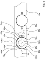
- a magnet means 64a could also be arranged within the operating means carrier unit 10a which extends annularly in the circumferential direction 68a of the functional field 12a and has different poles N, S in the circumferential direction 68a, as shown in FIG FIG. 2 is indicated schematically.
- the disc-shaped operating means 14a comprises a pot-shaped lid 90a, which forms a flat cover surface 91a ( FIG. 4 ).
- the lid 90a is made of plastic and is painted in a desired color.
- a magnetizable conducting means 70a of the operating means 14a Arranged in an inner receiving area formed by the lid 90a is a magnetizable conducting means 70a of the operating means 14a, which is provided in a functional state for forwarding magnetic field lines in the radial direction 74a to the axis of rotation 32a of the functional field 12a and the operating means 14a.
- the conductive means 70a is formed by a bending stamped part made of sheet metal.
- the guide means 70a has an inner, circular area 92a, which forms on its side facing the lid 90a a bearing surface 94a, with which the guide means 70a rests in the mounted state on an inner side of the lid 90a.
- the area 92a forms a contact surface with which the conducting means 70a abuts, when mounted, on a cover side of a disk-shaped magnet 96a intended to magnetise the conducting means 70a or to guide its magnetic field lines radially outwards by means of the conducting means 70a.
- the guiding means 70a starting from the region 92a, has arms 98a which extend radially outwards and are uniformly distributed over the circumference, namely 18 pieces.
- the arms 98a cooperate in the functionally arranged state of the operating means 14a with the functional means 84a formed by MR sensors for generating setting signals and with the functional means 80a arranged laterally next to the operating means receiving area 62a for generating detent forces.
- the magnet 96a cooperates with the function means 86a to generate a holding force in the direction of the rotation axis 32a.
- the diametrically opposed with respect to the rotation axis 32 a MR sensors together with the arms 98 a serve to generate setting signals during a rotational movement of the operating means 14 a as well as a tilting movement of the operating means 14 a.
- functional means 84a ', 84a "formed by sensors, in particular MR sensors, may also be provided in addition to the functional means 84a, which may preferably be arranged in a common circular quadrant, as shown schematically in FIG FIG. 2 is shown.
- the operating device has a sensor unit 36a comprising the MR sensors and an evaluation unit 38a which are provided for movement of the operating means 14a in a region 42a differing from an actuating region 40a, in each case one opposite the actuating region 40a with respect to the rotation axis 32a Area 42a, to record and evaluate ( FIG. 3 ).
- a signal resulting from an increasing distance parallel to the rotation axis 32a between the guide means 70a and the MR sensors on a region 42a opposite the actuation region 40a is evaluated by means of the evaluation unit 38a.
- a tilting axis 108a is provided perpendicular to a front edge or to a longitudinal extent of the control panel around which the operating means 14a has to be pivoted for adjustment (FIG. FIG. 2 ).
- the operating means 14a By means of a rotational movement of the operating means 14a about its axis of rotation 32a, power levels can be selected, while by means of tilting movements different sizes of hotplates, a cooking time, a locking position, etc. can be adjusted. In principle, however, further settings that appear reasonable to a person skilled in the art are also conceivable by means of a tilting movement.
- symbols for the tilting functions are printed on the operating means carrier unit 10a in the region of the tilting axis 108a.
- the disc-shaped magnet 96a is arranged in the mounted state in an annular retaining means 100a of a bottom cover 102a ( FIG. 4 ).
- the bottom lid 102a has molded, hook-shaped latching means 104a, by means of which the bottom lid 102a is locked in the lid 90a in the mounted state.
- the bottom cover 102a has a larger diameter than the cover 90a, so that it protrudes in the radial direction over side walls of the lid 90a (see. Figures 3 and 3a ).
- a resulting supernatant 106a is intended to avoid as much as possible a contact between the lid 90a and the edge region of the operating means receiving area 62a, whereby lacquer damage to the lid 90a can be avoided.
- the bottom lid 102a has a slightly concave, in particular conical, bearing surface 103a ( FIG. 3 ).
- FIGS. 5 to 11 Alternative embodiments are shown. Substantially identical components, features and functions are basically numbered by the same reference numerals. To distinguish the embodiments, however, the reference numerals of the embodiments, the letters a to g are added. The following description is essentially limited to the differences from the embodiment in the FIGS. 1 to 4 , wherein with respect to the same components, features and functions on the description of the embodiment in the FIGS. 1 to 4 can be referenced. Furthermore, it should be noted that as an alternative and / or in addition to features and / or functions of one of the embodiments, features and / or functions of another of the embodiments may be provided.
- FIG. 5 is a section of a sectional view through a hob control device with a control panel carrier unit 10b formed by a control panel shown.
- the operating-device carrier unit 10b has contour elements 16b which are provided for realizing operating functions deviating from a rotational movement 18b about an axis of rotation 32b.
- the contour elements 16b are formed by material-tapered regions of the operating-device carrier unit 10b which transmit a pressure force exerted on an operating means 14b Pressure sensors 44 b are provided.
- the contour element 16b or the material-tapered region of the operating-medium carrier unit 10b is formed by a wall part between a recess 52b forming an operating-medium receiving region 62b and a recess 54b, which is arranged opposite the recess 52b.
- the recesses 52b, 54b are arranged round and coaxial with the axis of rotation 32b, wherein the recess 54b has a smaller diameter than the recess 52b.
- the diameter of the recess 52b is advantageously greater than 50% and, as shown in the illustrated embodiment, greater than 70% of the diameter of the recess 54b, whereby the pressure sensors 44b can be advantageously positioned in a radially outer region of the operating means receiving portion 62b.
- an advantageous support area having a greater wall thickness than the wall portion directly between the recesses 52b, 54b.
- the wall part directly between the recesses 52b, 54b has a wall thickness 110b of less than 1 mm.
- the pressure sensors 44b formed by piezo sensors are arranged diametrically opposite relative to the axis of rotation 32b and are arranged on a common carrier plate 112b. Additionally or alternatively, however, a pressure sensor could also be arranged in the middle region of the operating means receiving region 62b.
- the cooktop operating device comprises a functional means receiving area 60b which is arranged laterally next to the operating means receiving area 62b and is intended to receive functional means 80b for a first operating means 14b and functional means 82b for a second operating means 14b '.
- the functional means receiving area 60b is formed by a recess 56b on a side of the operating means carrier unit 10b facing away from the operating means receiving area 62b, which together with the recess 52b forms a resistance reducing means 48b.
- the functional means 80b, 82b are arranged on a common carrier plate 114b.
- a detection of a rotational movement takes place in the embodiment in FIG. 5 according to the in FIG. 2 illustrated embodiment, with two non-illustrated, below the Whyschfact Schemes 62b arranged, formed by MR sensors functional means, which may also be preferably mounted on the support plate 114b. Alternatively, functional means formed by sensors could also be arranged laterally next to the operating means receiving area 62b, preferably in the functional means receiving area 60b.
- FIG. 6 shows a cooktop operating device with a control panel carrier unit formed by a control panel 10c.
- the cooktop operating device comprises a single operating means 14c and a single function field 12c, which are provided for the operation of several cooking zones.
- the cooktop operating device basically corresponds to its structure of the cooktop operating device of the FIGS. 1 to 4 and comprises a corresponding contour element 16c for implementing tilting functions, wherein the contour element 16c has an inclined surface 20c arranged in a bottom region of an operating means receiving region 62c.
- the hob operating device preferably has two tilting axes 116c, 118c with respect to the operating means 14c, under each of which two diametrically opposed functional means 84c, formed by magnetic sensors, namely by MR sensors (magnetoresistive sensors), are arranged are.
- the hotplates can be selected, by means of multiple tilting movements different sizes could be selected in the cooking zones and by means of a subsequent rotary movement 18c of the operating means 14c about a rotation axis 32c, power levels of the selected hotplate can be set.
- the tilting axes 116c, 118c intersect at an angle other than 90 °, whereby the functional means 84c can be advantageously positioned. In principle, more than two tilting axes 116c, 118c are conceivable.
- functional means receiving areas 60c are arranged with function means 80c formed by magnets for generating a magnetic detent force or a holding force in defined rotational positions.
- the hob control device comprises FIG. 6 the embodiment of the FIGS. 1 to 4 corresponding resistance reducing means 46c, 48c.
- FIG. 7 shows a schematically illustrated section of a sectional view of a cooktop operating device, which is essentially the hob operating device FIG. 5 equivalent.
- the cooktop operating device comprises an operating means 14d with a guide means 70d, which, corresponding to the guide means 70a, has outwardly extending arms 98d starting from an area 92d in the radial direction 74d.
- the arms 98d have two angled portions 120d, 122d, when viewed radially outward 74d, a first angled portion 120d toward a bottom lid 102d, after which the arms 98d extend obliquely toward the bottom lid 102d, and a second angled portion 122d opposing the first angled portion 120d so that the arms 98d after the angling 122d are reduced in distance with the bottom lid 102d from the angled portions 120d, 122d in the operative state of the operating means 14d along an inner surface of the bottom lid 102d.
- the cooktop operating device comprises a functional means receiving area 60d, which is formed by two recesses 54d, 56d arranged at different depths in a common section of an operating means carrier unit 10d, namely a first recess 56d, which is parallel to an axis of rotation 32d from one of a lowermost surface 124d extends beyond the control plane carrier unit 10d plane spanned above a plane defined by a support surface 28d of an operating means receiving portion 62d level.
- the second recess 54d extends from the plane defined by the lowermost surface 124d to a plane perpendicular to the rotation axis 32d and slightly extending from the operating means receiving portion 62d, starting from the plane defined by the lowermost surface 124d parallel to the rotation axis 32d Although with a distance less than 1 mm, is spaced.
- the recess 54d extends parallel to the plane spanned from the lowermost surface 124d to below two adjacent operating-medium receiving portions 62d, 62d '.
- functional means for the operating means 14d formed by pressure sensors 44d and functional means for the operating means 14d 'formed by pressure sensors 44d' are arranged, which are arranged on a common carrier plate 126d.
- the hob control device comprises FIG. 7 the embodiment FIG. 5 corresponding resistance reduction means 46d, 48d and a resistance reduction means 50d formed by a recess for a function means 86d formed by a magnet.
- FIG. 8 shows a schematic plan view of a hob control device with an operating means 14e.
- the operating means 14e comprises a guiding means 70e which, corresponding to the guiding means 70a, has outwardly extending arms 98e starting from an area 92e in the radial direction 74e.
- the arms 98e have in their radially outer region, viewed in the radial direction 74e outwardly, an angled portion 128e of 90 ° in the direction of a bottom cover 102e.
- the conducting means 70e is applied to a magnetic south pole of a magnet 96e, so that a magnetic south pole is also formed on its arms 98e ( Fig. 9 ).
- two functional means 84e formed by MR sensors are arranged in a functional means receiving area 61e arranged laterally adjacent to the operating means receiving area 62e, which are provided for detecting a rotational movement 18e of the operating means 14e, and with those downwards after the angled portions 128e in the direction of the bottom cover 102e extending legs of the arms 98e cooperate.
- An operating means carrier unit 10e of the cooktop operating device has a further guide means 72e.
- the guide means 72e is formed by an L-shaped sheet metal part with a first leg 130e and a second leg 132e.
- the conducting means 72e bears with the first limb 130e on a lower side of a functional means 86e formed by a permanent magnet and conducts magnetic field lines of the permanent magnet in the radial direction 74e from a rotation axis 32e of a functional field 12e or of the operating means 14e in one by means of the first limb 130e functional condition to the outside, in the radial direction 74e behind one of the functional means 84e.
- the second leg 132e extends, proceeding from the first leg 130e, parallel to the axis of rotation 32e in the direction of a cover surface 78e of the operator support unit 10e, over part of the functional means 84e so that planes perpendicular to the axis of rotation 32e extend through the functional means 84e as well can also be passed through the second leg 132e and in these levels advantageous magnetic field lines can be passed from the legs of the conductive agent 70e of the operating means 14e through the functional means 84e to the second leg 132e of the conductive agent 72e.
- the conducting means 72e is applied to a magnetic north pole of the functional means 86e, so that a magnetic north pole also forms on the leg 132e, and an advantageously directed magnetic field can be achieved by the functional means 84e.
- contoured elements formed by material rejuvenated areas of the operating means support unit 10e 16e pressure sensors 44e arranged.
- the contour elements 16e are provided for forwarding pressure forces exerted on the operating means 14e to the pressure sensors 44e.
- functional means receiving areas 60e are arranged with function means 80e formed by magnets for generating a magnetic detent force or a holding force in defined rotational positions.
- the hob control device comprises FIG. 8 the embodiment FIG. 5 corresponding resistance reducing means 46e, 48e and a resistance reduction means 50e formed by a recess for a function means 86e formed by a magnet.
- FIG. 10 a section of a hob control device is shown with an operating means 14f.
- the operating means 14f comprises a magnet means 64f which extends annularly in the circumferential direction 68f of a functional field 66f, by means of which the operating means 14f rests on a functional field 12f of an operating-medium carrier unit 10f in the functional state, or in the circumferential direction 68f of the circular-disk-shaped operating means 14f.
- the magnet means 64f has in the circumferential direction 68f evenly distributed alternately differing poles S, N, which are spaced apart in the radial direction 74f to a rotational axis 32f of the function field 66f and the operating means 14f differently.
- the magnet means 64f has on its outer periphery in the region of the poles S indentations, whereby in the radial direction 74f radially outwardly acting active surfaces of the poles S and the poles N are spaced apart from the axis of rotation 32f.
- the radially outwardly acting effective surfaces of the poles S are curved, namely concave, and the radially outwardly acting effective surfaces of the poles N are straight.
- the poles S, N cooperate with functional means 80f arranged diametrically opposite one another in the operating means carrier unit 10f with respect to the axis of rotation 32f.
- the magnet means 64f and the function means 80f are intended to generate magnetic latching forces, so that the operating means 14f is latched or held in defined rotational positions.
- the embodiments in the FIGS. 5 to 9 and 11 are according to the embodiment in the FIGS. 1 to 4 in the operating means carrier unit 10b - 10e; 10g annular magnet means 64b-64e; 64g shown schematically, but in principle would also be conceivable that in the embodiments of the embodiment in FIG. 10 appropriate operating means are used.
- Pressure sensors 44f are arranged below contoured elements 16f formed by material-tapered regions of the operating-medium carrier unit 10f.
- the contour elements 16f are provided for forwarding pressure forces exerted on the operating means 14f to the pressure sensors 44f.
- an operating means receiving area 62f On the side next to an operating means receiving area 62f are functional means receiving areas 60f with function means 80f formed by magnets for generating a magnetic detent force or a holding force in defined rotational positions.
- the hob control device comprises FIG. 10 the embodiment FIG. 5 corresponding resistance reduction means 46f, 48f.
- FIG. 11 a section of a hob control device is shown with an operating means 14g.
- the operating means 14g has bar magnets 134g which are distributed uniformly over the circumference and aligned with their longitudinal extent in the radial direction 74g and which have poles S, N which differ in the radial direction 74g from a rotation axis 32g of the operating means 14g in a functional state.
- the bar magnets 134g cooperate with functional means 80g arranged in an operating means carrier unit 10g of the operating device and also formed by bar magnets.
- the bar magnets 134g and the function means 80g are provided to generate magnetic latching forces, so that the operating means 14g engages or is held in defined rotational positions.
- Pressure sensors 44g are arranged under contour elements 16g formed by material-tapered regions of the operating-medium carrier unit 10g.
- the contour elements 16g are provided for forwarding pressure forces exerted on the operating means 14g to the pressure sensors 44g.
- the hob control device comprises FIG. 11 the embodiment FIG. 5 corresponding resistance reducing means 46g, 48g. reference numeral 10
- Base seat 70 30 distance
- guide means 32 axis of rotation
- direction 34 extension 76 side contour
- sensor unit 78 cover surface 38 evaluation 79
- Strength 46 Drag reduction means 90 cover 48
- Area 52 recess 94 contact surface 96 magnet 98 poor 100 holding means 102 bottom cover 104 latching means 106 Got over 108 tilt axis 110
Claims (14)
- Dispositif de commande d'une plaque de cuisson comprenant une unité porteuse de moyen de commande (10a - 10g) qui présente au moins un champ fonctionnel (12a - 12g) qui est ménagé pour le couplage à un moyen de commande (14a - 14g) amovible,
caractérisé en ce que
l'unité porteuse de moyen de commande (10a - 10g) présente au moins un moyen de réduction de résistance (46a - 50a ; 46b, 48b ; 46c, 48c ; 46d - 50d ; 46e - 50e ; 46f, 48f ; 46g, 48g) qui est ménagé pour réduire une résistance de signal et/ou une résistance de force de maintien pour une force de maintien qui est ménagée pour maintenir le moyen de commande amovible (14a - 14g) situé sur l'unité porteuse de moyen de commande (10a - 10g) dans une position conforme au fonctionnement et/ou dans une position enclenchée dans au moins une position de rotation définie, le moyen de réduction de résistance (46a - 50a ; 46b, 48b ; 46c, 48c ; 46d - 50d ; 46e - 50e ; 46f, 48f ; 46g, 48g) étant formé par au moins un évidement (52a - 58a ; 52b - 56b ; 52c, 56c ; 52d - 58d ; 52e - 58e ; 52f, 56f ; 52g, 56g), l'évidement (52a - 58a ; 52b - 56b ; 52c, 56c ; 52d - 58d ; 52e - 58e ; 52f, 56f ; 52g, 56g) étant une zone ayant une épaisseur de matériau réduite par rapport à une zone adjacente, et/ou l'unité porteuse de moyen de commande étant formée par différentes matières, le moyen de réduction de résistance (46a - 50a ; 46b, 48b ; 46c, 48c ; 46d - 50d ; 46e - 50e ; 46f, 48f ; 46g, 48g) étant formé par le matériau ayant une plus petite résistance de signal et/ou une plus petite résistance de force de maintien. - Dispositif de commande de plaque de cuisson selon la revendication 1,
caractérisé en ce que
le moyen de réduction de résistance (46a - 50a ; 46b, 48b ; 46c, 48c ; 46d - 50d ; 46e - 50e ; 46f, 48f ; 46g, 48g) est formé par au moins deux évidements (52a - 58a ; 52b - 56b ; 52c, 56c ; 52d - 58d ; 52e - 58e ; 52f, 56f ; 52g, 56g). - Dispositif de commande de plaque de cuisson selon la revendication 1 ou 2,
caractérisé en ce qu'
au moins un évidement (52a - 52g) formant en partie le moyen de réduction de résistance (46a - 50a ; 46b, 48b ; 46c, 48c ; 46d - 50d ; 46e - 50e ; 46f ; 46g) forme une zone de logement de moyen de commande (62a - 62g) pour le moyen de commande (14a - 14g). - Dispositif de commande de plaque de cuisson selon l'une quelconque des revendications précédentes,
caractérisé en ce que
l'unité porteuse de moyen de commande (10a -10g) présente au moins un élément de contour (16a - 16g) pour la réalisation d'au moins une fonction de commande différente d'un mouvement de rotation (18a - 18g). - Dispositif de commande de plaque de cuisson selon la revendication 4,
caractérisé en ce que
l'élément de contour (16a ; 16c) est ménagé pour la réalisation d'une fonction à bascule. - Dispositif de commande de plaque de cuisson selon la revendication 5,
caractérisé en ce que
l'élément de contour (16a ; 16c) présente une surface oblique (20a ; 20c) qui, dans un état conforme au fonctionnement, comprend un angle (24a) différent de zéro par rapport à un plan horizontal (22a), et/ou une surface bombée (26a). - Dispositif de commande de plaque de cuisson selon la revendication 6,
caractérisé en ce que
le champ fonctionnel (12a ; 12c) présente une surface d'appui de base (28a ; 28c) qui, dans au moins une zone, présente un écart (30a ; 30c) en direction radiale par rapport à un axe de rotation (32a ; 32c) du champ fonctionnel (12a ; 12c), lequel écart présente au moins 30% d'une distance maximale (34a ; 34c) du champ fonctionnel (12a ; 12c) en direction radiale par rapport à l'axe de rotation (32a ; 32c). - Dispositif de commande de plaque de cuisson selon l'une quelconque des revendications précédentes,
caractérisé par
au moins un capteur de pression (44a ; 44b ; 44d - 44g). - Dispositif de commande de plaque de cuisson selon l'une quelconque des revendications précédentes,
caractérisé en ce que
l'unité porteuse de moyen de commande (10a - 10g) présente au moins une zone de logement de moyen de commande (62a - 62g) dans laquelle le moyen de commande (14a - 14g) est disposé dans un état conforme au fonctionnement, et au moins une zone de logement de moyen de fonctionnement (60a - 60d ; 60e, 61e ; 60f, 60g) qui est disposée latéralement à côté de la zone de logement de moyen de commande (62a - 62g). - Dispositif de commande de plaque de cuisson d'un appareil ménager selon l'une quelconque des revendications précédentes, comprenant une unité de moyens de commande (10a - 10e ; 14f, 10g) qui présente au moins un moyen à aimant (64a - 64g) et au moins un champ fonctionnel (12a - 12e ; 66f ; 12g) qui est ménagé pour le couplage amovible à au moins une autre unité de moyens de commande (14a - 14e ; 10f; 14g),
caractérisé en ce que
le moyen à aimant (64a - 64g) s'étend au moins en forme de segment annulaire en direction circonférentielle (68a - 68g) du champ fonctionnel (12a - 12e ; 66f ; 12g). - Dispositif de commande de plaque de cuisson selon l'une quelconque des revendications précédentes,
caractérisé par
au moins un moyen de guidage (70a ; 70d ; 70e, 72e) magnétisable, qui, dans un état conforme au fonctionnement, est ménagé pour le transfert de lignes de champ magnétiques en direction radiale (74a ; 74d ; 74e) par rapport à un axe de rotation (32a ; 32d ; 32e) du champ fonctionnel (12e) et/ou du moyen de commande (14a ; 14d ; 14e). - Dispositif de commande de plaque de cuisson selon l'une quelconque des revendications précédentes,
caractérisé en ce que
l'unité porteuse de moyen de commande (10a - 10g) est formée au moins en partie par un bandeau de commande. - Dispositif de commande de plaque de cuisson selon l'une quelconque des revendications précédentes,
caractérisé par
au moins un moyen de commande (14a - 14g) amovible qui est ménagé pour le couplage au champ fonctionnel (12a - 12g) et qui, dans un état couplé au champ fonctionnel (12a - 12g), de manière conforme au fonctionnement, dépasse au-delà d'au moins un contour latéral (76a ; 76c ; 76e ; 76f ; 76g) et/ou au-delà d'au moins une surface de recouvrement (78a - 78g) de l'unité porteuse de moyen de commande (10a - 10g). - Dispositif de commande de plaque de cuisson selon l'une quelconque des revendications précédentes,
caractérisé en ce que
le champ fonctionnel (12c) est ménagé pour la commande d'au moins deux emplacements de cuisson.
Priority Applications (1)
| Application Number | Priority Date | Filing Date | Title |
|---|---|---|---|
| PL10704110T PL2389785T3 (pl) | 2009-01-23 | 2010-01-13 | Urządzenie obsługujące sprzętu gospodarstwa domowego |
Applications Claiming Priority (2)
| Application Number | Priority Date | Filing Date | Title |
|---|---|---|---|
| DE200910000383 DE102009000383A1 (de) | 2009-01-23 | 2009-01-23 | Bedienvorrichtung eines Haushaltsgeräts |
| PCT/EP2010/050315 WO2010084063A1 (fr) | 2009-01-23 | 2010-01-13 | Dispositif de commande d'un appareil électroménager |
Publications (2)
| Publication Number | Publication Date |
|---|---|
| EP2389785A1 EP2389785A1 (fr) | 2011-11-30 |
| EP2389785B1 true EP2389785B1 (fr) | 2016-11-23 |
Family
ID=42041774
Family Applications (1)
| Application Number | Title | Priority Date | Filing Date |
|---|---|---|---|
| EP10704110.5A Active EP2389785B1 (fr) | 2009-01-23 | 2010-01-13 | Dispositif de commande d'un appareil électroménager |
Country Status (5)
| Country | Link |
|---|---|
| EP (1) | EP2389785B1 (fr) |
| DE (1) | DE102009000383A1 (fr) |
| ES (1) | ES2607854T3 (fr) |
| PL (1) | PL2389785T3 (fr) |
| WO (1) | WO2010084063A1 (fr) |
Families Citing this family (5)
| Publication number | Priority date | Publication date | Assignee | Title |
|---|---|---|---|---|
| DE102010040676A1 (de) * | 2010-09-14 | 2012-03-15 | BSH Bosch und Siemens Hausgeräte GmbH | Bedienvorrichtung für ein Hausgerät sowie Hausgerät mit einer derartigen Bedienvorrichtung |
| DE102011004007B4 (de) * | 2011-02-11 | 2020-03-26 | Siemens Aktiengesellschaft | Eingabevorrichtung für ein Feldgerät zur Prozessinstrumentierung sowie Verfahren zur Detektion einer Betätigung einer Taste einer derartigen Eingabevorrichtung |
| DE102011080770A1 (de) * | 2011-08-10 | 2013-02-14 | BSH Bosch und Siemens Hausgeräte GmbH | Bedieneinrichtung für ein Hausgerät sowie Hausgerät mit einer entsprechenden Bedieneinrichtung |
| DE102012200292A1 (de) * | 2012-01-11 | 2013-07-11 | BSH Bosch und Siemens Hausgeräte GmbH | Bedieneinrichtung für ein Haushaltsgerät sowie Haushaltsgerät mit einer derartigen Bedieneinrichtung |
| GB2577041A (en) | 2018-09-06 | 2020-03-18 | Gamesman Ltd | Button assembly |
Family Cites Families (14)
| Publication number | Priority date | Publication date | Assignee | Title |
|---|---|---|---|---|
| DE19825310A1 (de) * | 1998-06-05 | 1999-12-09 | Bsh Bosch Siemens Hausgeraete | Bedieneinheit für ein elektrisches Haushaltsgerät |
| DE10035592A1 (de) * | 2000-07-21 | 2002-01-31 | Ego Elektro Geraetebau Gmbh | Anordnung zur Steuerung von elektrisch ansteuerbaren Geräten, insbesondere Elektrowärmegeräten |
| DE10212953B4 (de) * | 2002-03-19 | 2005-05-04 | E.G.O. Elektro-Gerätebau GmbH | Bedienvorrichtung für ein Elektrogerät |
| DE10212929A1 (de) * | 2002-03-19 | 2003-10-02 | Ego Elektro Geraetebau Gmbh | Bedienvorrichtung für ein Elektrogerät |
| DE10229629A1 (de) * | 2002-07-02 | 2004-01-29 | BSH Bosch und Siemens Hausgeräte GmbH | Vorrichtung zur Steuerung von elektrisch ansteuerbaren Geräten, insbesondere von elektrischen Haushaltsgeräten |
| ATE459032T1 (de) * | 2002-08-14 | 2010-03-15 | Bsh Bosch Siemens Hausgeraete | Bedieneinheit für ein elektrisches haushaltsgerät |
| DE10248993A1 (de) * | 2002-10-21 | 2004-04-29 | BSH Bosch und Siemens Hausgeräte GmbH | Betätigungsvorrichtung für eine Kochmulde |
| DE102004020825B4 (de) * | 2004-04-28 | 2021-08-12 | BSH Hausgeräte GmbH | Bedienelement |
| JP2005339896A (ja) * | 2004-05-25 | 2005-12-08 | Mitsubishi Electric Corp | 押圧操作装置 |
| DE202004017133U1 (de) * | 2004-11-05 | 2005-02-03 | BSH Bosch und Siemens Hausgeräte GmbH | Bedieneinrichtung für ein Kochfeld |
| DE202005019978U1 (de) | 2005-10-12 | 2006-04-20 | E.G.O. Elektro-Gerätebau GmbH | Bedienvorrichtung für ein Elektrogerät |
| DE102005049995A1 (de) * | 2005-10-12 | 2007-04-19 | E.G.O. Elektro-Gerätebau GmbH | Bedienvorrichtung für ein Elektrogerät und Bedienverfahren zur Bedienung eines Elektrogerätes |
| DE102006045735A1 (de) | 2006-09-18 | 2008-03-27 | E.G.O. Elektro-Gerätebau GmbH | Bedienvorrichtung für ein Elektrogerät und Bedienverfahren |
| DE102007016466B3 (de) * | 2007-03-16 | 2008-08-21 | E.G.O. Elektro-Gerätebau GmbH | Bedienungseinrichtung für ein Kochfeld und Anordnung eines Kochfelds mit einer solchen Bedienungseinrichtung |
-
2009
- 2009-01-23 DE DE200910000383 patent/DE102009000383A1/de not_active Withdrawn
-
2010
- 2010-01-13 EP EP10704110.5A patent/EP2389785B1/fr active Active
- 2010-01-13 WO PCT/EP2010/050315 patent/WO2010084063A1/fr active Application Filing
- 2010-01-13 ES ES10704110.5T patent/ES2607854T3/es active Active
- 2010-01-13 PL PL10704110T patent/PL2389785T3/pl unknown
Also Published As
| Publication number | Publication date |
|---|---|
| PL2389785T3 (pl) | 2017-06-30 |
| WO2010084063A1 (fr) | 2010-07-29 |
| ES2607854T3 (es) | 2017-04-04 |
| DE102009000383A1 (de) | 2010-07-29 |
| EP2389785A1 (fr) | 2011-11-30 |
Similar Documents
| Publication | Publication Date | Title |
|---|---|---|
| EP2389541B1 (fr) | Dispositif de commande d'un appareil électroménager | |
| EP2389785B1 (fr) | Dispositif de commande d'un appareil électroménager | |
| EP2389542B1 (fr) | Dispositif de commande d'un appareil électroménager | |
| DE102011083524B4 (de) | Dreh-/Drück-Bedienvorrichtung für ein Mensch-Maschine-Interface | |
| EP2366926B1 (fr) | Dispositif de reconnaissance de position finale dans des soupapes à levée, kit de soupape et module de capteur associé | |
| EP2737380B1 (fr) | Dispositif de commande | |
| DE102004049011A1 (de) | Drehsteller | |
| EP2342501B1 (fr) | Four à cuisson | |
| EP2389543B1 (fr) | Appareil ménager | |
| EP2475220A1 (fr) | Dispositif de champ de cuisson | |
| DE10035592A1 (de) | Anordnung zur Steuerung von elektrisch ansteuerbaren Geräten, insbesondere Elektrowärmegeräten | |
| EP2161643B1 (fr) | Dispositif de commande | |
| DE102013212815A1 (de) | Bedienvorrichtung mit einem Bedienelement mit einem Haftelement an der Bedienelementunterseite sowie Haushaltsgerät mit einer derartigen Bedienvorrichtung | |
| EP2669582A1 (fr) | Appareil ménager avec manette rotative | |
| DE10212953A1 (de) | Bedienvorrichtung für ein Elektrogerät | |
| EP3028536B1 (fr) | Système de table de cuisson | |
| EP3383135B1 (fr) | Système de cuisson avec une unité de positionnement | |
| DE102013212814A1 (de) | Bedienvorrichtung mit einem Bedienelement mit Magnete gehaltene Kappe und Sockel sowie Haushaltsgerät mit einer derartigen Bedienvorrichtung | |
| DE102005063070A1 (de) | Vorrichtung zum Steuern eines Betriebsparameters eines elektrischen Geräts | |
| DE102016206477A1 (de) | Bedieneinrichtung für ein Elektrogerät und Elektrogerät | |
| EP2483601B1 (fr) | Appareil électroménager | |
| DE102010040675A1 (de) | Bedienvorrichtung für ein Hausgerät sowie Hausgerät mit einer derartigen Bedienvorrichtung | |
| EP2092644A2 (fr) | Dispositif de commande pour un appareil électrique comportant des interrupteurs tactiles et procédé de mise en circuit d'un appareil de chauffage supplémentaire | |
| EP3509392B1 (fr) | Procédé pour une plaque de cuisson | |
| EP2420733B1 (fr) | Dispositif de champ de cuisson |
Legal Events
| Date | Code | Title | Description |
|---|---|---|---|
| PUAI | Public reference made under article 153(3) epc to a published international application that has entered the european phase |
Free format text: ORIGINAL CODE: 0009012 |
|
| 17P | Request for examination filed |
Effective date: 20110823 |
|
| AK | Designated contracting states |
Kind code of ref document: A1 Designated state(s): AT BE BG CH CY CZ DE DK EE ES FI FR GB GR HR HU IE IS IT LI LT LU LV MC MK MT NL NO PL PT RO SE SI SK SM TR |
|
| DAX | Request for extension of the european patent (deleted) | ||
| RAP1 | Party data changed (applicant data changed or rights of an application transferred) |
Owner name: BSH HAUSGERAETE GMBH |
|
| 17Q | First examination report despatched |
Effective date: 20150612 |
|
| GRAP | Despatch of communication of intention to grant a patent |
Free format text: ORIGINAL CODE: EPIDOSNIGR1 |
|
| INTG | Intention to grant announced |
Effective date: 20160624 |
|
| RIN1 | Information on inventor provided before grant (corrected) |
Inventor name: WILSDORF, GERD Inventor name: MARBACH, ANDREAS Inventor name: WURNITSCH, ERNST Inventor name: HACKBARTH, ANDREAS Inventor name: HUBER, JOHANN |
|
| GRAS | Grant fee paid |
Free format text: ORIGINAL CODE: EPIDOSNIGR3 |
|
| GRAA | (expected) grant |
Free format text: ORIGINAL CODE: 0009210 |
|
| AK | Designated contracting states |
Kind code of ref document: B1 Designated state(s): AT BE BG CH CY CZ DE DK EE ES FI FR GB GR HR HU IE IS IT LI LT LU LV MC MK MT NL NO PL PT RO SE SI SK SM TR |
|
| REG | Reference to a national code |
Ref country code: GB Ref legal event code: FG4D Free format text: NOT ENGLISH |
|
| REG | Reference to a national code |
Ref country code: CH Ref legal event code: EP |
|
| REG | Reference to a national code |
Ref country code: IE Ref legal event code: FG4D Free format text: LANGUAGE OF EP DOCUMENT: GERMAN |
|
| REG | Reference to a national code |
Ref country code: AT Ref legal event code: REF Ref document number: 848888 Country of ref document: AT Kind code of ref document: T Effective date: 20161215 |
|
| REG | Reference to a national code |
Ref country code: DE Ref legal event code: R096 Ref document number: 502010012766 Country of ref document: DE |
|
| REG | Reference to a national code |
Ref country code: FR Ref legal event code: PLFP Year of fee payment: 8 |
|
| PG25 | Lapsed in a contracting state [announced via postgrant information from national office to epo] |
Ref country code: LV Free format text: LAPSE BECAUSE OF FAILURE TO SUBMIT A TRANSLATION OF THE DESCRIPTION OR TO PAY THE FEE WITHIN THE PRESCRIBED TIME-LIMIT Effective date: 20161123 |
|
| REG | Reference to a national code |
Ref country code: LT Ref legal event code: MG4D |
|
| REG | Reference to a national code |
Ref country code: NL Ref legal event code: MP Effective date: 20161123 |
|
| PG25 | Lapsed in a contracting state [announced via postgrant information from national office to epo] |
Ref country code: LT Free format text: LAPSE BECAUSE OF FAILURE TO SUBMIT A TRANSLATION OF THE DESCRIPTION OR TO PAY THE FEE WITHIN THE PRESCRIBED TIME-LIMIT Effective date: 20161123 Ref country code: NL Free format text: LAPSE BECAUSE OF FAILURE TO SUBMIT A TRANSLATION OF THE DESCRIPTION OR TO PAY THE FEE WITHIN THE PRESCRIBED TIME-LIMIT Effective date: 20161123 Ref country code: SE Free format text: LAPSE BECAUSE OF FAILURE TO SUBMIT A TRANSLATION OF THE DESCRIPTION OR TO PAY THE FEE WITHIN THE PRESCRIBED TIME-LIMIT Effective date: 20161123 Ref country code: GR Free format text: LAPSE BECAUSE OF FAILURE TO SUBMIT A TRANSLATION OF THE DESCRIPTION OR TO PAY THE FEE WITHIN THE PRESCRIBED TIME-LIMIT Effective date: 20170224 Ref country code: NO Free format text: LAPSE BECAUSE OF FAILURE TO SUBMIT A TRANSLATION OF THE DESCRIPTION OR TO PAY THE FEE WITHIN THE PRESCRIBED TIME-LIMIT Effective date: 20170223 |
|
| PG25 | Lapsed in a contracting state [announced via postgrant information from national office to epo] |
Ref country code: PT Free format text: LAPSE BECAUSE OF FAILURE TO SUBMIT A TRANSLATION OF THE DESCRIPTION OR TO PAY THE FEE WITHIN THE PRESCRIBED TIME-LIMIT Effective date: 20170323 Ref country code: FI Free format text: LAPSE BECAUSE OF FAILURE TO SUBMIT A TRANSLATION OF THE DESCRIPTION OR TO PAY THE FEE WITHIN THE PRESCRIBED TIME-LIMIT Effective date: 20161123 Ref country code: BE Free format text: LAPSE BECAUSE OF NON-PAYMENT OF DUE FEES Effective date: 20170131 Ref country code: HR Free format text: LAPSE BECAUSE OF FAILURE TO SUBMIT A TRANSLATION OF THE DESCRIPTION OR TO PAY THE FEE WITHIN THE PRESCRIBED TIME-LIMIT Effective date: 20161123 |
|
| PG25 | Lapsed in a contracting state [announced via postgrant information from national office to epo] |
Ref country code: DK Free format text: LAPSE BECAUSE OF FAILURE TO SUBMIT A TRANSLATION OF THE DESCRIPTION OR TO PAY THE FEE WITHIN THE PRESCRIBED TIME-LIMIT Effective date: 20161123 Ref country code: EE Free format text: LAPSE BECAUSE OF FAILURE TO SUBMIT A TRANSLATION OF THE DESCRIPTION OR TO PAY THE FEE WITHIN THE PRESCRIBED TIME-LIMIT Effective date: 20161123 Ref country code: SK Free format text: LAPSE BECAUSE OF FAILURE TO SUBMIT A TRANSLATION OF THE DESCRIPTION OR TO PAY THE FEE WITHIN THE PRESCRIBED TIME-LIMIT Effective date: 20161123 Ref country code: RO Free format text: LAPSE BECAUSE OF FAILURE TO SUBMIT A TRANSLATION OF THE DESCRIPTION OR TO PAY THE FEE WITHIN THE PRESCRIBED TIME-LIMIT Effective date: 20161123 Ref country code: CZ Free format text: LAPSE BECAUSE OF FAILURE TO SUBMIT A TRANSLATION OF THE DESCRIPTION OR TO PAY THE FEE WITHIN THE PRESCRIBED TIME-LIMIT Effective date: 20161123 |
|
| REG | Reference to a national code |
Ref country code: DE Ref legal event code: R097 Ref document number: 502010012766 Country of ref document: DE |
|
| PG25 | Lapsed in a contracting state [announced via postgrant information from national office to epo] |
Ref country code: BG Free format text: LAPSE BECAUSE OF FAILURE TO SUBMIT A TRANSLATION OF THE DESCRIPTION OR TO PAY THE FEE WITHIN THE PRESCRIBED TIME-LIMIT Effective date: 20170223 Ref country code: SM Free format text: LAPSE BECAUSE OF FAILURE TO SUBMIT A TRANSLATION OF THE DESCRIPTION OR TO PAY THE FEE WITHIN THE PRESCRIBED TIME-LIMIT Effective date: 20161123 |
|
| REG | Reference to a national code |
Ref country code: CH Ref legal event code: PL |
|
| PG25 | Lapsed in a contracting state [announced via postgrant information from national office to epo] |
Ref country code: MC Free format text: LAPSE BECAUSE OF FAILURE TO SUBMIT A TRANSLATION OF THE DESCRIPTION OR TO PAY THE FEE WITHIN THE PRESCRIBED TIME-LIMIT Effective date: 20161123 |
|
| PLBE | No opposition filed within time limit |
Free format text: ORIGINAL CODE: 0009261 |
|
| STAA | Information on the status of an ep patent application or granted ep patent |
Free format text: STATUS: NO OPPOSITION FILED WITHIN TIME LIMIT |
|
| PG25 | Lapsed in a contracting state [announced via postgrant information from national office to epo] |
Ref country code: CH Free format text: LAPSE BECAUSE OF NON-PAYMENT OF DUE FEES Effective date: 20170131 Ref country code: LI Free format text: LAPSE BECAUSE OF NON-PAYMENT OF DUE FEES Effective date: 20170131 |
|
| 26N | No opposition filed |
Effective date: 20170824 |
|
| REG | Reference to a national code |
Ref country code: IE Ref legal event code: MM4A |
|
| PG25 | Lapsed in a contracting state [announced via postgrant information from national office to epo] |
Ref country code: LU Free format text: LAPSE BECAUSE OF NON-PAYMENT OF DUE FEES Effective date: 20170113 Ref country code: SI Free format text: LAPSE BECAUSE OF FAILURE TO SUBMIT A TRANSLATION OF THE DESCRIPTION OR TO PAY THE FEE WITHIN THE PRESCRIBED TIME-LIMIT Effective date: 20161123 |
|
| REG | Reference to a national code |
Ref country code: FR Ref legal event code: PLFP Year of fee payment: 9 |
|
| REG | Reference to a national code |
Ref country code: BE Ref legal event code: MM Effective date: 20170131 |
|
| PG25 | Lapsed in a contracting state [announced via postgrant information from national office to epo] |
Ref country code: IE Free format text: LAPSE BECAUSE OF NON-PAYMENT OF DUE FEES Effective date: 20170113 |
|
| REG | Reference to a national code |
Ref country code: AT Ref legal event code: MM01 Ref document number: 848888 Country of ref document: AT Kind code of ref document: T Effective date: 20170113 |
|
| PG25 | Lapsed in a contracting state [announced via postgrant information from national office to epo] |
Ref country code: AT Free format text: LAPSE BECAUSE OF NON-PAYMENT OF DUE FEES Effective date: 20170113 |
|
| PG25 | Lapsed in a contracting state [announced via postgrant information from national office to epo] |
Ref country code: MT Free format text: LAPSE BECAUSE OF FAILURE TO SUBMIT A TRANSLATION OF THE DESCRIPTION OR TO PAY THE FEE WITHIN THE PRESCRIBED TIME-LIMIT Effective date: 20161123 |
|
| PG25 | Lapsed in a contracting state [announced via postgrant information from national office to epo] |
Ref country code: HU Free format text: LAPSE BECAUSE OF FAILURE TO SUBMIT A TRANSLATION OF THE DESCRIPTION OR TO PAY THE FEE WITHIN THE PRESCRIBED TIME-LIMIT; INVALID AB INITIO Effective date: 20100113 |
|
| PG25 | Lapsed in a contracting state [announced via postgrant information from national office to epo] |
Ref country code: CY Free format text: LAPSE BECAUSE OF NON-PAYMENT OF DUE FEES Effective date: 20161123 |
|
| PG25 | Lapsed in a contracting state [announced via postgrant information from national office to epo] |
Ref country code: MK Free format text: LAPSE BECAUSE OF FAILURE TO SUBMIT A TRANSLATION OF THE DESCRIPTION OR TO PAY THE FEE WITHIN THE PRESCRIBED TIME-LIMIT Effective date: 20161123 |
|
| PGFP | Annual fee paid to national office [announced via postgrant information from national office to epo] |
Ref country code: ES Payment date: 20200219 Year of fee payment: 11 Ref country code: IT Payment date: 20200122 Year of fee payment: 11 |
|
| PGFP | Annual fee paid to national office [announced via postgrant information from national office to epo] |
Ref country code: TR Payment date: 20200109 Year of fee payment: 11 |
|
| PG25 | Lapsed in a contracting state [announced via postgrant information from national office to epo] |
Ref country code: IS Free format text: LAPSE BECAUSE OF FAILURE TO SUBMIT A TRANSLATION OF THE DESCRIPTION OR TO PAY THE FEE WITHIN THE PRESCRIBED TIME-LIMIT Effective date: 20170323 |
|
| REG | Reference to a national code |
Ref country code: ES Ref legal event code: FD2A Effective date: 20220426 |
|
| PG25 | Lapsed in a contracting state [announced via postgrant information from national office to epo] |
Ref country code: IT Free format text: LAPSE BECAUSE OF NON-PAYMENT OF DUE FEES Effective date: 20210113 |
|
| PG25 | Lapsed in a contracting state [announced via postgrant information from national office to epo] |
Ref country code: TR Free format text: LAPSE BECAUSE OF NON-PAYMENT OF DUE FEES Effective date: 20210113 |
|
| PG25 | Lapsed in a contracting state [announced via postgrant information from national office to epo] |
Ref country code: ES Free format text: LAPSE BECAUSE OF NON-PAYMENT OF DUE FEES Effective date: 20210114 |
|
| REG | Reference to a national code |
Ref country code: DE Ref legal event code: R084 Ref document number: 502010012766 Country of ref document: DE |
|
| PGFP | Annual fee paid to national office [announced via postgrant information from national office to epo] |
Ref country code: FR Payment date: 20230123 Year of fee payment: 14 |
|
| PGFP | Annual fee paid to national office [announced via postgrant information from national office to epo] |
Ref country code: PL Payment date: 20230103 Year of fee payment: 14 Ref country code: GB Payment date: 20230124 Year of fee payment: 14 Ref country code: DE Payment date: 20230131 Year of fee payment: 14 |