EP2388095B2 - Outil de fraisage - Google Patents
Outil de fraisage Download PDFInfo
- Publication number
- EP2388095B2 EP2388095B2 EP11165410.9A EP11165410A EP2388095B2 EP 2388095 B2 EP2388095 B2 EP 2388095B2 EP 11165410 A EP11165410 A EP 11165410A EP 2388095 B2 EP2388095 B2 EP 2388095B2
- Authority
- EP
- European Patent Office
- Prior art keywords
- chip
- milling cutter
- machining
- milling
- receiving region
- Prior art date
- Legal status (The legal status is an assumption and is not a legal conclusion. Google has not performed a legal analysis and makes no representation as to the accuracy of the status listed.)
- Not-in-force
Links
Images


Classifications
-
- B—PERFORMING OPERATIONS; TRANSPORTING
- B23—MACHINE TOOLS; METAL-WORKING NOT OTHERWISE PROVIDED FOR
- B23C—MILLING
- B23C5/00—Milling-cutters
- B23C5/02—Milling-cutters characterised by the shape of the cutter
- B23C5/10—Shank-type cutters, i.e. with an integral shaft
-
- B—PERFORMING OPERATIONS; TRANSPORTING
- B23—MACHINE TOOLS; METAL-WORKING NOT OTHERWISE PROVIDED FOR
- B23C—MILLING
- B23C2210/00—Details of milling cutters
- B23C2210/40—Flutes, i.e. chip conveying grooves
-
- B—PERFORMING OPERATIONS; TRANSPORTING
- B23—MACHINE TOOLS; METAL-WORKING NOT OTHERWISE PROVIDED FOR
- B23C—MILLING
- B23C2210/00—Details of milling cutters
- B23C2210/40—Flutes, i.e. chip conveying grooves
- B23C2210/402—Flutes, i.e. chip conveying grooves of variable depth
-
- B—PERFORMING OPERATIONS; TRANSPORTING
- B23—MACHINE TOOLS; METAL-WORKING NOT OTHERWISE PROVIDED FOR
- B23C—MILLING
- B23C2226/00—Materials of tools or workpieces not comprising a metal
- B23C2226/27—Composites, e.g. fibre reinforced composites
Definitions
- the present invention relates to a milling cutter for machining bodies according to the preamble of independent claim 1.
- Such milling tools are mainly used on robotic milling machines and on CNC milling machines for machining, for example, non-metals such as plastics, wood, glass fiber, carbon and the like.
- the known from the prior art cutter tools have the disadvantage that the maximum possible feed, d. H. the movement of the cutter into the tool or along the workpiece, can not be exploited to the maximum.
- the chip can not be removed from the milling site at a sufficiently high speed, and thus clogging or blocking and / or blunting of the milling cutter takes place, as a result of which it can be damaged or destroyed.
- US 2002/090273 A1 discloses a rotary multi-cutter cutting tool equipped with two roughing cutters and two small finishing blades.
- This multi-cutting cutting tool can in particular also represent a milling tool.
- Behind the roughing or finishing cutting edges appropriate roughing or smaller sizing grooves are provided, which helically rotate helically around the cutting tool main body in the longitudinal direction of the multi-blade cutting tool.
- This embodiment is advantageous since at least one main chip removal area and one subsidiary chip removal area are formed by the differently configured chip receiving areas. At the time when the main chip discharge portion does not receive any more material, for example, because the processing portion formed thereon does not cooperate with the material to be processed, it is possible that the subsidiary chip discharge portion is used to discharge chip.
- the first chip receiving area in the circumferential direction extends many times further than the first chip receiving area is preferably to refer to the geometric design of the cross-sectional area of the body in the area of the chip receiving areas. It is hereby to be understood in particular that the two edges delimiting the first chip receiving area from the peripheral surface of the base body are substantially more widely spaced from one another than the edges delimiting the second chip receiving area from the peripheral surface of the main body. The distance between the edges bounding the respective chip receiving area can also be referred to as width.
- the factor "multiple” is understood as an arbitrary multiple, integer or non-integer multiple and thus also more than 4 times multiple.
- This solution according to the invention is also advantageous, since the pressure acting on the milling cutter during milling with the milling cutter according to the invention even in systems with only low rotational speeds, such as. 20000 revolutions, is taken from the cutting edge of the milling cutter through the second cutting edge and the second machining section, respectively.
- the mill according to the invention offers e.g. the advantage that the required speed can be lowered due to the small blade on the back and the support material does not melt at a high accuracy of milling.
- the second cutting edge or small cutting edge has a groove depth which is 60-70% smaller than the groove depth of the main groove, it is preferably produced with a pointed disc and reduces the pressure from the cutting edge with the large groove (former cut-in milling cutter).
- a multiplicity of first and / or second chip receiving areas are formed on the main body.
- This embodiment has the advantage that z. B. depending on the particular cutter tool diameter and / or the application area or application area of the milling tool different geometries can be realized.
- a first chip receiving area and 2, 3, 4 or more second chip receiving areas are provided.
- a second chip receiving area and 2, 3, 4 or a plurality of first chip receiving areas can be provided and preferably the same number of second chip picking areas can be provided corresponding to the number of first chip receiving areas.
- a total of any number, for example, 2, 3, 4 or more cutting can be formed on the cutter tool.
- the milling tools are right-hand cutting and / or left-hand cutting tools as well as right-hand spiral or left-hand spiral tools.
- the milling cutter according to the invention can have different pitches, for example in one processing section or two processing sections.
- the rake angle and / or the clearance angle depending on the application or depending on other geometric properties are dependent or completely independent adjustable.
- the rake angle and the clearance angle of the first and second processing section are identical, with differently designed chip and clearance angles also being advantageous.
- the at least partially machined edge is provided or formed on the first and / or second chip receiving area.
- This edge is advantageous because it facilitates leakage of the chip from the respective chip receiving area, since the chip receiving area is partially smaller due to the grinding of this edge, d. H. preferably less enclosing, is formed. This has the advantage that the chip can be removed more easily or solves more easily from the cutter tool. It can also be spoken of an enlarged opening angle.
- the edge is at least partially abraded over the entire length of the processing section, preferably over two-thirds of the length of the processing section, and more preferably over half of the processing section.
- the milling cutter tool has an end face in the region of the machining section, which face is at least partially inclined with respect to a plane extending at right angles to the axis of rotation.
- This embodiment is advantageous because the end face can be provided, for example, with one or more parts of an inclined plane, a curved section having the shape and / or with the corresponding negative mold such that one or more arbitrarily formed end cutting edges can be provided or formed or formed are.
- individual portions of the inclined end face are flat or curved and extend in the direction or opposite to the longitudinal direction of the base body.
- At least one of the chip receiving portions has a waveform different from a circular arc portion.
- the chip receiving area can have such a geometry that is suitable, for example, in conjunction with the centrifugal force to allow optimized removal of the chip. It is also conceivable that the chip receiving area is formed as a circular arc section or has planar portions.
- the ratio of the width of the first chip receiving area to the depth of the first chip receiving area is greater than the ratio of the width of the second chip receiving area to the depth of the second chip receiving area.
- the base body has a shank portion with a diameter which is larger than the diameter of the machining portion.
- This embodiment is advantageous because the cutter is thus provided with a higher stability.
- the cutter made of a material selected from the group consisting at least of high-speed steel (ASS), hard metal, cermet and / or the like.
- This embodiment is advantageous since, depending on size, field of application, geometric design and / or similar factors, the optimal material for the milling cutter can be selected.
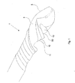
- a milling cutter 1 which has a first cutting edge 5 and a second cutting edge 50.
- the first cutting edge 5 therefore preferably represents a first processing section and the second cutting edge 50 preferably represents a second processing section.
- a first chip receiving area 4, which adjoins the first cutting edge 5 changes in the circumferential direction a multiple extends further than the second chip receiving space 12, which adjoins the second cutting edge 50.
- the second cutting edge 50 is preferably arranged on the back of the milling cutter 1, that is, offset from the main cutting edge 5, which is likewise formed on the milling cutter 1, or the first machining section.
- the second cutting edge 50 is offset by 45 ° -315 ° and particularly preferably by 90 ° -270 ° or by approximately 180 ° or by exactly 180 ° or arranged to rotate about a central axis.
- the depth of the chip receiving groove 12 adjoining the second cutting edge 50 is less than the depth of the first cutting chip 4. It is also conceivable that both chip receiving chambers 5, 50 or all chip receiving chambers 5, 50 (should more than two be provided) have the same or different depths. It is thus also conceivable that a plurality of small cutting edges 50 with small groove depths (in comparison to the groove depth of the main cutting edge 5) can be attached to the back of the milling cutter 1.
- the term groove depth describes the depth of the respective chip space 5, 50. Further, the Fig.
- first chip receiving chambers 4 and / or the second chip receiving chambers 12 have enlargement regions 10.
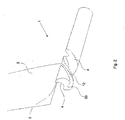
- Fig. 2 shows a three-dimensional representation of the milling cutter 1 and a machining tool 8.
- the adjoining the second blade 5 chip receiving space 4 is preferably gas-grained with a very pointed disc 8, ie that the machining tool 8 used to produce the second chip receiving space 4 preferably has different physical properties than that Machining tool 3 used for machining the first chip receiving space 4.
- the shape, the composition and / or the like can be understood. This has the advantage that the stability of the milling cutter 1 is not impaired. It is quite conceivable that even with a two-, three- or four-cutter one or more small grooves on the back attaches or forms, in order to reduce the pressure on the cutting edge 5 and the main cutting edges.
- This embodiment can be provided with right-hand spiral and left spiral milling cutters 1 as well as with right-cutting and left-cutting cutters or tools.
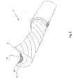
- Fig. 3 shows a milling cutter 1 with only one cutting edge 5, wherein the chip receiving space 4 is also modified by a magnification area 10.
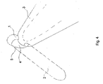
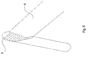
- Fig. 4 shows a milling cutter 1, which is at least partially formed by an at least partially machined and particularly preferably substantially cylindrical base body 2 and in which by means of a machining tool 3, which is preferably a tool for machining, a chip receiving area 4 in the base body 2 is preferably formed spirally becomes.
- the machining tool 3 may, in addition to other tools, preferably be a grinding tool or a milling tool. With the machining tool 3 or another machining tool is in the in Fig. 4 shown Processing step in which the chip receiving area 4 is formed or in a subsequent processing step, in addition to generating the chip receiving area 4 preferably also the cutting edge 5 of the cutter tool 1 on the base body 2, in particular in the region of the transition between the chip receiving area 4 and the base body peripheral surface, formed.
- the cutting edge 5 forms an angle with respect to the peripheral surface. This angle can be the same or different for multiple cutting edges.
- the chip receiving area 4 is represented by a spherical, preferably arcuate and particularly preferably part-circular curve or the first curve portion 7.
- the first curve portion 7 or the chip receiving area 4 preferably extends only in a region of the cross-sectional area of the milling tool 1, wherein the area particularly preferably extends over at most half of the cross-sectional area and / or not over the center 6 of the main body 2.
- the chip receiving area 4 is limited, for example, by the cutting edge 5 and the edge 9.
- a further processing step is shown.
- the main body 2 is thereby by means of another tool 8 or a similar or the same tool, such as in Fig. 4 , preferably machined.
- the chip receiving area 4 is increased, whereby a better chip removal can take place.
- the enlargement of the chip receiving area 4 takes place here by forming a preferably wave-shaped body edge of the milling cutter tool 1.
- the preferably wave-shaped body edge can be taken, for example, from different cross sections through the milling cutter tool 1.
- a cross-section preferably takes place in the plane perpendicular to the axis of rotation or to the center 6 of the base body 2. Due to the chip receiving region 4 extending spirally on the base body 2 in the longitudinal direction or in the direction of the axis of rotation, the wave-shaped curve is differently inclined or inclined in different cross sections . oriented.
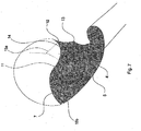
- Fig. 7 It can be seen that the magnification 10 of the chip receiving area 4 a processing or grinding or milling the edge 9 (see. Fig. 5 ) corresponds.
- the resulting new body edge 13 and the second curve portion 14 has linear or spherical, preferably arcuate or part-circular curve portions. It is also conceivable that the transition from the first curve portion 7 of the chip receiving area 4 to the second or further curve portion 14 is flowing or by an abrupt change in pitch or an abrupt change in slope.
- Fig. 7 is such an abrupt change in slope, which is referred to by the reference numeral 11 as a transition can be seen.
- the second curve portion 14 in a cross-sectional view the same radius or a larger radius than the first curve portion 7.
- the radius of the second curve portion 14 is smaller than the radius of the first curve portion 7. Wherein the radius also in each case as the average distance to a curve center 15a, 15b can be understood.
- the chip receiving area 4 is limited, for example, by the cutting edge 5 and the transition 11 or the edge 13, which delimits the second curve portion 14 relative to the peripheral surface 21 of the base body 2.
- Fig. 8 discloses a further illustration of the main body 2, in which a further chip receiving area 12 is incorporated into the main body 2 with a machining tool 3, 8.
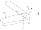
- Fig. 9 is also a further illustration of the base body 2 is shown, in this base body 2, the second curve portion 14 is incorporated by means of another machining tool 8. It is conceivable in this case that by means of the machining tools 3, 8 or other machining tools, further cam portions or grooves or the like, which are always different from the cam portions 7, 14, are always incorporated over the same basic body length and / or different basic body length portions in the longitudinal direction of the rotational axis.
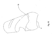
- Fig. 10 a further perspective view of the cutter tool 1 is shown, wherein the cutter tool 1 in the chip receiving area 4 has a survey 16.
- This elevation 16 is triangular in shape and extends spirally starting from the end face 20, in particular an end face, at least partially and preferably over a third, half, three quarters or the entire length of the chip receiving area. 4
- Fig. 11 is a perspective view of the cutter tool 1 to remove, wherein the cutter tool 1 in this illustration has substantially uniformly formed chip receiving areas 4.
- the chip receiving areas 4, 12 have different depths and different radii. Depth here is preferred as the respective minimum distance of the respective chip receiving area 4, 12 to understand the axis of rotation 6.
- Fig. 12 discloses a cutter tool 1, the cross-section of which have body edges which are wave-shaped. It can be deduced from the fact that the term "wave-like" does not necessarily mean uniformly formed mutually facing curved sections, but also greatly varying curve sections, such as the chip receiving area 4, the grooves 17, 18 and the elevation 16 can be understood. It is also conceivable that instead of or in addition to the survey 16 further surveys are provided. This also applies to the grooves 17, 18, whereby instead of the grooves 17, 18 or in addition to the grooves 17, 18 more similar and / or differently shaped grooves can be provided.
- Fig. 13 is that in Fig. 12 shown cutter tool 1 without removing the machining tool 8.
Claims (9)
- Outil de fraisage (1) destiné à l'usinage par enlèvement de copeaux de corps en matière plastique, comportant un corps de base (2) réalisé sous forme de corps rotatif, sur lequel sont réalisés au moins un premier et un deuxième tronçon d'usinage (5, 50) qui s'étendent chacun au moins partiellement en forme de spirale autour d'un axe de rotation (6), lesdits tronçons d'usinage (5, 50) pouvant être amenés en contact avec le corps en matière plastique pour le processus de fraisage et comportant chacun des zones de réception de copeaux (4, 12) raccordées et écartées l'une de l'autre, destinées à évacuer la matière enlevée, la première zone de réception de copeaux (4) s'étendant dans le sens périphérique sur une plus grande longueur que la deuxième zone de réception de copeaux (12), à savoir plus de quatre fois la longueur de celle-ci, afin d'absorber une pression exercée sur l'outil de fraisage (1) pendant le fraisage par l'arête de coupe de la fraise à travers le deuxième tronçon d'usinage (50),
caractérisé en ce qu'
au moins une des zones de réception de copeaux (4, 12) est délimitée à côté du tronçon d'usinage (5, 50) par une arête (9) usinée, en plus, au moins partiellement, ladite arête (9) usinée, en plus, au moins partiellement formant, d'une part, une zone d'agrandissement (10) d'au moins la première zone de réception de copeaux (4), ainsi que, d'autre part, une nouvelle arête (13) du corps, les deux arêtes délimitant la première zone de réception de copeaux (4) vis-à-vis d'une surface périphérique du corps de base (2) étant plus écartées l'une de l'autre que les arêtes délimitant la deuxième zone de réception de copeaux (12) vis-à-vis de la surface périphérique du corps de base (2), le deuxième tronçon d'usinage (50) ayant une profondeur de rainure qui est inférieure de 60-70 % à la profondeur de rainure du premier tronçon d'usinage (5). - Outil de fraisage (1) selon la revendication 1,
caractérisé en ce que
l'arête (9) est affûtée au moins en partie, sur au moins un tiers, de préférence la moitié et encore mieux sur les deux tiers de la longueur des tronçons d'usinage (5, 50). - Outil de fraisage (1) selon la revendication 1 ou 2,
caractérisé en ce qu'
une pluralité de premières et/ou deuxièmes zones de réception de copeaux (4, 12) sont réalisées sur le corps de base (2). - Outil de fraisage (1) selon au moins l'une quelconque des revendications précédentes,
caractérisé en ce que
l'outil de fraisage (1) comporte, dans le tronçon d'usinage (5, 50), une face frontale (20) qui est inclinée, au moins par zones, par rapport à un plan s'étendant perpendiculairement à l'axe de rotation (6). - Outil de fraisage (1) selon la revendication 4,
caractérisé en ce que
différentes parties de la face frontale (20) inclinée sont planes ou courbes et s'étendent dans le sens ou dans le sens opposé à la direction longitudinale du corps de base (2). - Outil de fraisage (1) selon au moins l'une quelconque des revendications précédentes,
caractérisé en ce qu'
au moins une des zones de réception de copeaux (4, 12) possède une forme courbe, qui est différente d'une zone en arc de cercle. - Outil de fraisage (1) selon au moins l'une quelconque des revendications précédentes,
caractérisé en ce que
le rapport entre la largeur de la première zone de réception de copeaux (4) et la profondeur de la première zone de réception de copeaux (4) est plus grand que le rapport entre la largeur de la deuxième zone de réception de copeaux (12) et la profondeur de la deuxième zone de réception de copeaux (12). - Outil de fraisage (1) selon au moins l'une quelconque des revendications précédentes,
caractérisé en ce que
le corps de base (2) comporte une partie formant tige avec un diamètre supérieur au diamètre du tronçon d'usinage. - Outil de fraisage (1) selon au moins l'une quelconque des revendications précédentes,
caractérisé en ce que
le matériau de la fraise est choisi au moins proportionnellement parmi au moins un des matériaux du groupe constitué au moins d'un acier rapide (HSS), d'un métal dur, d'un cermet et/ou d'un matériau similaire.
Priority Applications (1)
| Application Number | Priority Date | Filing Date | Title |
|---|---|---|---|
| PL11165410T PL2388095T5 (pl) | 2010-05-21 | 2011-05-10 | Narzędzie do frezowania |
Applications Claiming Priority (2)
| Application Number | Priority Date | Filing Date | Title |
|---|---|---|---|
| DE102010022189 | 2010-05-21 | ||
| DE102010027496A DE102010027496B4 (de) | 2010-05-21 | 2010-07-16 | Fräswerkzeug |
Publications (3)
| Publication Number | Publication Date |
|---|---|
| EP2388095A1 EP2388095A1 (fr) | 2011-11-23 |
| EP2388095B1 EP2388095B1 (fr) | 2014-09-03 |
| EP2388095B2 true EP2388095B2 (fr) | 2018-04-18 |
Family
ID=44230104
Family Applications (1)
| Application Number | Title | Priority Date | Filing Date |
|---|---|---|---|
| EP11165410.9A Not-in-force EP2388095B2 (fr) | 2010-05-21 | 2011-05-10 | Outil de fraisage |
Country Status (3)
| Country | Link |
|---|---|
| EP (1) | EP2388095B2 (fr) |
| DE (1) | DE102010027496B4 (fr) |
| PL (1) | PL2388095T5 (fr) |
Families Citing this family (1)
| Publication number | Priority date | Publication date | Assignee | Title |
|---|---|---|---|---|
| DE102010033106B4 (de) * | 2010-05-21 | 2013-11-07 | Rudolf Wendling | Fräswerkzeug |
Citations (2)
| Publication number | Priority date | Publication date | Assignee | Title |
|---|---|---|---|---|
| DE3742942C1 (en) † | 1987-12-18 | 1988-12-08 | Rolf Klenk Gmbh & Co Kg | Milling tool for roughing and smoothing workpieces |
| US20020090273A1 (en) † | 2001-01-10 | 2002-07-11 | Serwa Ronald K. | Roughing and finishing rotary tool apparatus and method |
Family Cites Families (9)
| Publication number | Priority date | Publication date | Assignee | Title |
|---|---|---|---|---|
| DE3308478A1 (de) * | 1982-03-17 | 1983-09-29 | Uwe 7717 Immendingen Reich | Schaftfraeser |
| DE3623176A1 (de) * | 1986-07-10 | 1988-01-28 | Kwo Werkzeuge Gmbh | Verfahren zur herstellung eines nutfraesers und danach hergestellter nutfraeser |
| JPH06320323A (ja) * | 1993-05-19 | 1994-11-22 | Toshiba Tungaloy Co Ltd | 切削工具 |
| IL131119A0 (en) * | 1999-07-26 | 2001-01-28 | Hanita Metal Works Ltd | Milling cutter |
| JP2006150572A (ja) * | 2004-12-01 | 2006-06-15 | Osg Corp | ボロンドープダイヤモンド被膜およびダイヤモンド被覆加工工具 |
| DE102005002698B4 (de) * | 2005-01-19 | 2007-06-21 | Franken GmbH + Co KG Fabrik für Präzisionswerkzeuge | Fräswerkzeug |
| DE102005020513B3 (de) * | 2005-04-29 | 2006-09-14 | Näpflin, Schleiftechnik AG | Einstückiger Schaftfräser |
| DE202006014089U1 (de) * | 2006-09-11 | 2007-01-11 | Speed Tiger Precision Technology Co., Ltd. | Fräser |
| EP2093003A1 (fr) * | 2008-02-20 | 2009-08-26 | Fraisa Holding AG | Outil de fraisage complet |
-
2010
- 2010-07-16 DE DE102010027496A patent/DE102010027496B4/de not_active Revoked
-
2011
- 2011-05-10 EP EP11165410.9A patent/EP2388095B2/fr not_active Not-in-force
- 2011-05-10 PL PL11165410T patent/PL2388095T5/pl unknown
Patent Citations (2)
| Publication number | Priority date | Publication date | Assignee | Title |
|---|---|---|---|---|
| DE3742942C1 (en) † | 1987-12-18 | 1988-12-08 | Rolf Klenk Gmbh & Co Kg | Milling tool for roughing and smoothing workpieces |
| US20020090273A1 (en) † | 2001-01-10 | 2002-07-11 | Serwa Ronald K. | Roughing and finishing rotary tool apparatus and method |
Also Published As
| Publication number | Publication date |
|---|---|
| PL2388095T3 (pl) | 2015-04-30 |
| DE102010027496A1 (de) | 2011-11-24 |
| EP2388095B1 (fr) | 2014-09-03 |
| DE102010027496B4 (de) | 2013-08-08 |
| EP2388095A1 (fr) | 2011-11-23 |
| PL2388095T5 (pl) | 2018-08-31 |
Similar Documents
| Publication | Publication Date | Title |
|---|---|---|
| EP0937528B1 (fr) | Alésoir et sa méthode de production | |
| EP1864737B1 (fr) | Outil d'usinage par enlevement de copeaux | |
| EP2403673B2 (fr) | Fraise à queue | |
| EP1511590B1 (fr) | Fraise avec rayon de surfaçage | |
| WO2016020047A1 (fr) | Outil de fraisage | |
| DE102018001477A1 (de) | Anfaswerkzeug und Verfahren zum Anfasen von Verzahnungen | |
| EP2848342B1 (fr) | Outil de fraisage complet pour l'usinage rotatif de matériaux | |
| EP3132875B1 (fr) | Outil de fraisage | |
| EP2929966B1 (fr) | Outil de fraisage complet pour l'usinage rotatif de matériaux | |
| DE19824212B4 (de) | Hartmetall-Kugelschneidkopfschaftfräser | |
| EP3743234B1 (fr) | Outil de fraisage | |
| EP2916985B1 (fr) | Outil annulaire destiné à usiner une pièce | |
| EP0485546B1 (fr) | Garniture de coupe pour outils | |
| WO2017198265A1 (fr) | Fraise à queue | |
| DE102005058536B4 (de) | Schneidwerkzeugsystem, insbesondere zum Verzahnen von Kegelrädern im Einzel-Teil-Verfahren | |
| EP2388095B2 (fr) | Outil de fraisage | |
| DE102016109130B4 (de) | Schaftfräser | |
| DE202017103021U1 (de) | Schaftfräser | |
| DE202017103022U1 (de) | Schaftfräser | |
| EP1954434A1 (fr) | Tete de mesure de fraisage | |
| DE202016102635U1 (de) | Schaftfräser | |
| DE102010033106B4 (de) | Fräswerkzeug | |
| EP1577060B1 (fr) | Outil à entailler | |
| EP3804906B1 (fr) | Procédé de fabrication d'une géométrie de coupe coté extérieur dans un outil à tige de matériau plein destiné au traitement des matériaux | |
| EP4015123A1 (fr) | Outil de fraisage complet destiné à l'usinage rotatif des materiaux |
Legal Events
| Date | Code | Title | Description |
|---|---|---|---|
| AK | Designated contracting states |
Kind code of ref document: A1 Designated state(s): AL AT BE BG CH CY CZ DE DK EE ES FI FR GB GR HR HU IE IS IT LI LT LU LV MC MK MT NL NO PL PT RO RS SE SI SK SM TR |
|
| AX | Request for extension of the european patent |
Extension state: BA ME |
|
| PUAI | Public reference made under article 153(3) epc to a published international application that has entered the european phase |
Free format text: ORIGINAL CODE: 0009012 |
|
| 17P | Request for examination filed |
Effective date: 20120420 |
|
| 17Q | First examination report despatched |
Effective date: 20130408 |
|
| GRAP | Despatch of communication of intention to grant a patent |
Free format text: ORIGINAL CODE: EPIDOSNIGR1 |
|
| INTG | Intention to grant announced |
Effective date: 20140429 |
|
| GRAS | Grant fee paid |
Free format text: ORIGINAL CODE: EPIDOSNIGR3 |
|
| GRAA | (expected) grant |
Free format text: ORIGINAL CODE: 0009210 |
|
| AK | Designated contracting states |
Kind code of ref document: B1 Designated state(s): AL AT BE BG CH CY CZ DE DK EE ES FI FR GB GR HR HU IE IS IT LI LT LU LV MC MK MT NL NO PL PT RO RS SE SI SK SM TR |
|
| REG | Reference to a national code |
Ref country code: GB Ref legal event code: FG4D Free format text: NOT ENGLISH |
|
| REG | Reference to a national code |
Ref country code: CH Ref legal event code: EP Ref country code: AT Ref legal event code: REF Ref document number: 685292 Country of ref document: AT Kind code of ref document: T Effective date: 20140915 |
|
| REG | Reference to a national code |
Ref country code: IE Ref legal event code: FG4D Free format text: LANGUAGE OF EP DOCUMENT: GERMAN |
|
| REG | Reference to a national code |
Ref country code: DE Ref legal event code: R096 Ref document number: 502011004245 Country of ref document: DE Effective date: 20141016 |
|
| PG25 | Lapsed in a contracting state [announced via postgrant information from national office to epo] |
Ref country code: LT Free format text: LAPSE BECAUSE OF FAILURE TO SUBMIT A TRANSLATION OF THE DESCRIPTION OR TO PAY THE FEE WITHIN THE PRESCRIBED TIME-LIMIT Effective date: 20140903 Ref country code: GR Free format text: LAPSE BECAUSE OF FAILURE TO SUBMIT A TRANSLATION OF THE DESCRIPTION OR TO PAY THE FEE WITHIN THE PRESCRIBED TIME-LIMIT Effective date: 20141204 Ref country code: ES Free format text: LAPSE BECAUSE OF FAILURE TO SUBMIT A TRANSLATION OF THE DESCRIPTION OR TO PAY THE FEE WITHIN THE PRESCRIBED TIME-LIMIT Effective date: 20140903 Ref country code: SE Free format text: LAPSE BECAUSE OF FAILURE TO SUBMIT A TRANSLATION OF THE DESCRIPTION OR TO PAY THE FEE WITHIN THE PRESCRIBED TIME-LIMIT Effective date: 20140903 Ref country code: FI Free format text: LAPSE BECAUSE OF FAILURE TO SUBMIT A TRANSLATION OF THE DESCRIPTION OR TO PAY THE FEE WITHIN THE PRESCRIBED TIME-LIMIT Effective date: 20140903 Ref country code: NO Free format text: LAPSE BECAUSE OF FAILURE TO SUBMIT A TRANSLATION OF THE DESCRIPTION OR TO PAY THE FEE WITHIN THE PRESCRIBED TIME-LIMIT Effective date: 20141203 |
|
| REG | Reference to a national code |
Ref country code: SK Ref legal event code: T3 Ref document number: E 17527 Country of ref document: SK |
|
| REG | Reference to a national code |
Ref country code: NL Ref legal event code: VDEP Effective date: 20140903 |
|
| REG | Reference to a national code |
Ref country code: LT Ref legal event code: MG4D Ref country code: DE Ref legal event code: R026 Ref document number: 502011004245 Country of ref document: DE |
|
| PG25 | Lapsed in a contracting state [announced via postgrant information from national office to epo] |
Ref country code: HR Free format text: LAPSE BECAUSE OF FAILURE TO SUBMIT A TRANSLATION OF THE DESCRIPTION OR TO PAY THE FEE WITHIN THE PRESCRIBED TIME-LIMIT Effective date: 20140903 Ref country code: LV Free format text: LAPSE BECAUSE OF FAILURE TO SUBMIT A TRANSLATION OF THE DESCRIPTION OR TO PAY THE FEE WITHIN THE PRESCRIBED TIME-LIMIT Effective date: 20140903 Ref country code: CY Free format text: LAPSE BECAUSE OF FAILURE TO SUBMIT A TRANSLATION OF THE DESCRIPTION OR TO PAY THE FEE WITHIN THE PRESCRIBED TIME-LIMIT Effective date: 20140903 Ref country code: RS Free format text: LAPSE BECAUSE OF FAILURE TO SUBMIT A TRANSLATION OF THE DESCRIPTION OR TO PAY THE FEE WITHIN THE PRESCRIBED TIME-LIMIT Effective date: 20140903 |
|
| PLBI | Opposition filed |
Free format text: ORIGINAL CODE: 0009260 |
|
| PG25 | Lapsed in a contracting state [announced via postgrant information from national office to epo] |
Ref country code: NL Free format text: LAPSE BECAUSE OF FAILURE TO SUBMIT A TRANSLATION OF THE DESCRIPTION OR TO PAY THE FEE WITHIN THE PRESCRIBED TIME-LIMIT Effective date: 20140903 |
|
| 26 | Opposition filed |
Opponent name: HUFSCHMIED ZERSPANUNGSSYSTEME GMBH Effective date: 20150225 |
|
| PG25 | Lapsed in a contracting state [announced via postgrant information from national office to epo] |
Ref country code: PT Free format text: LAPSE BECAUSE OF FAILURE TO SUBMIT A TRANSLATION OF THE DESCRIPTION OR TO PAY THE FEE WITHIN THE PRESCRIBED TIME-LIMIT Effective date: 20150105 Ref country code: IS Free format text: LAPSE BECAUSE OF FAILURE TO SUBMIT A TRANSLATION OF THE DESCRIPTION OR TO PAY THE FEE WITHIN THE PRESCRIBED TIME-LIMIT Effective date: 20150103 Ref country code: RO Free format text: LAPSE BECAUSE OF FAILURE TO SUBMIT A TRANSLATION OF THE DESCRIPTION OR TO PAY THE FEE WITHIN THE PRESCRIBED TIME-LIMIT Effective date: 20140903 Ref country code: EE Free format text: LAPSE BECAUSE OF FAILURE TO SUBMIT A TRANSLATION OF THE DESCRIPTION OR TO PAY THE FEE WITHIN THE PRESCRIBED TIME-LIMIT Effective date: 20140903 |
|
| REG | Reference to a national code |
Ref country code: PL Ref legal event code: T3 |
|
| REG | Reference to a national code |
Ref country code: DE Ref legal event code: R026 Ref document number: 502011004245 Country of ref document: DE Effective date: 20150225 |
|
| PLAX | Notice of opposition and request to file observation + time limit sent |
Free format text: ORIGINAL CODE: EPIDOSNOBS2 |
|
| PG25 | Lapsed in a contracting state [announced via postgrant information from national office to epo] |
Ref country code: DK Free format text: LAPSE BECAUSE OF FAILURE TO SUBMIT A TRANSLATION OF THE DESCRIPTION OR TO PAY THE FEE WITHIN THE PRESCRIBED TIME-LIMIT Effective date: 20140903 |
|
| PLAF | Information modified related to communication of a notice of opposition and request to file observations + time limit |
Free format text: ORIGINAL CODE: EPIDOSCOBS2 |
|
| PG25 | Lapsed in a contracting state [announced via postgrant information from national office to epo] |
Ref country code: IT Free format text: LAPSE BECAUSE OF FAILURE TO SUBMIT A TRANSLATION OF THE DESCRIPTION OR TO PAY THE FEE WITHIN THE PRESCRIBED TIME-LIMIT Effective date: 20140903 |
|
| PLBB | Reply of patent proprietor to notice(s) of opposition received |
Free format text: ORIGINAL CODE: EPIDOSNOBS3 |
|
| PG25 | Lapsed in a contracting state [announced via postgrant information from national office to epo] |
Ref country code: SI Free format text: LAPSE BECAUSE OF FAILURE TO SUBMIT A TRANSLATION OF THE DESCRIPTION OR TO PAY THE FEE WITHIN THE PRESCRIBED TIME-LIMIT Effective date: 20140903 |
|
| REG | Reference to a national code |
Ref country code: CH Ref legal event code: PL |
|
| GBPC | Gb: european patent ceased through non-payment of renewal fee |
Effective date: 20150510 |
|
| PG25 | Lapsed in a contracting state [announced via postgrant information from national office to epo] |
Ref country code: LU Free format text: LAPSE BECAUSE OF FAILURE TO SUBMIT A TRANSLATION OF THE DESCRIPTION OR TO PAY THE FEE WITHIN THE PRESCRIBED TIME-LIMIT Effective date: 20150510 Ref country code: MC Free format text: LAPSE BECAUSE OF FAILURE TO SUBMIT A TRANSLATION OF THE DESCRIPTION OR TO PAY THE FEE WITHIN THE PRESCRIBED TIME-LIMIT Effective date: 20140903 Ref country code: CH Free format text: LAPSE BECAUSE OF NON-PAYMENT OF DUE FEES Effective date: 20150531 Ref country code: LI Free format text: LAPSE BECAUSE OF NON-PAYMENT OF DUE FEES Effective date: 20150531 |
|
| REG | Reference to a national code |
Ref country code: IE Ref legal event code: MM4A |
|
| REG | Reference to a national code |
Ref country code: FR Ref legal event code: ST Effective date: 20160129 |
|
| PG25 | Lapsed in a contracting state [announced via postgrant information from national office to epo] |
Ref country code: GB Free format text: LAPSE BECAUSE OF NON-PAYMENT OF DUE FEES Effective date: 20150510 Ref country code: IE Free format text: LAPSE BECAUSE OF NON-PAYMENT OF DUE FEES Effective date: 20150510 |
|
| PG25 | Lapsed in a contracting state [announced via postgrant information from national office to epo] |
Ref country code: FR Free format text: LAPSE BECAUSE OF NON-PAYMENT OF DUE FEES Effective date: 20150601 |
|
| PG25 | Lapsed in a contracting state [announced via postgrant information from national office to epo] |
Ref country code: MT Free format text: LAPSE BECAUSE OF FAILURE TO SUBMIT A TRANSLATION OF THE DESCRIPTION OR TO PAY THE FEE WITHIN THE PRESCRIBED TIME-LIMIT Effective date: 20140903 |
|
| PG25 | Lapsed in a contracting state [announced via postgrant information from national office to epo] |
Ref country code: HU Free format text: LAPSE BECAUSE OF FAILURE TO SUBMIT A TRANSLATION OF THE DESCRIPTION OR TO PAY THE FEE WITHIN THE PRESCRIBED TIME-LIMIT; INVALID AB INITIO Effective date: 20110510 Ref country code: BG Free format text: LAPSE BECAUSE OF FAILURE TO SUBMIT A TRANSLATION OF THE DESCRIPTION OR TO PAY THE FEE WITHIN THE PRESCRIBED TIME-LIMIT Effective date: 20140903 Ref country code: SM Free format text: LAPSE BECAUSE OF FAILURE TO SUBMIT A TRANSLATION OF THE DESCRIPTION OR TO PAY THE FEE WITHIN THE PRESCRIBED TIME-LIMIT Effective date: 20140903 |
|
| REG | Reference to a national code |
Ref country code: AT Ref legal event code: MM01 Ref document number: 685292 Country of ref document: AT Kind code of ref document: T Effective date: 20160510 |
|
| PG25 | Lapsed in a contracting state [announced via postgrant information from national office to epo] |
Ref country code: BE Free format text: LAPSE BECAUSE OF NON-PAYMENT OF DUE FEES Effective date: 20150531 |
|
| PG25 | Lapsed in a contracting state [announced via postgrant information from national office to epo] |
Ref country code: TR Free format text: LAPSE BECAUSE OF FAILURE TO SUBMIT A TRANSLATION OF THE DESCRIPTION OR TO PAY THE FEE WITHIN THE PRESCRIBED TIME-LIMIT Effective date: 20140903 Ref country code: AT Free format text: LAPSE BECAUSE OF NON-PAYMENT OF DUE FEES Effective date: 20160510 |
|
| PUAH | Patent maintained in amended form |
Free format text: ORIGINAL CODE: 0009272 |
|
| STAA | Information on the status of an ep patent application or granted ep patent |
Free format text: STATUS: PATENT MAINTAINED AS AMENDED |
|
| 27A | Patent maintained in amended form |
Effective date: 20180418 |
|
| AK | Designated contracting states |
Kind code of ref document: B2 Designated state(s): AL AT BE BG CH CY CZ DE DK EE ES FI FR GB GR HR HU IE IS IT LI LT LU LV MC MK MT NL NO PL PT RO RS SE SI SK SM TR |
|
| REG | Reference to a national code |
Ref country code: DE Ref legal event code: R102 Ref document number: 502011004245 Country of ref document: DE |
|
| PG25 | Lapsed in a contracting state [announced via postgrant information from national office to epo] |
Ref country code: MK Free format text: LAPSE BECAUSE OF FAILURE TO SUBMIT A TRANSLATION OF THE DESCRIPTION OR TO PAY THE FEE WITHIN THE PRESCRIBED TIME-LIMIT Effective date: 20140903 |
|
| PGFP | Annual fee paid to national office [announced via postgrant information from national office to epo] |
Ref country code: CZ Payment date: 20180502 Year of fee payment: 8 Ref country code: DE Payment date: 20180517 Year of fee payment: 8 Ref country code: SK Payment date: 20180427 Year of fee payment: 8 |
|
| PGFP | Annual fee paid to national office [announced via postgrant information from national office to epo] |
Ref country code: PL Payment date: 20180507 Year of fee payment: 8 |
|
| REG | Reference to a national code |
Ref country code: SK Ref legal event code: T5 Ref document number: E 17527 Country of ref document: SK |
|
| PG25 | Lapsed in a contracting state [announced via postgrant information from national office to epo] |
Ref country code: AL Free format text: LAPSE BECAUSE OF FAILURE TO SUBMIT A TRANSLATION OF THE DESCRIPTION OR TO PAY THE FEE WITHIN THE PRESCRIBED TIME-LIMIT Effective date: 20140903 |
|
| REG | Reference to a national code |
Ref country code: DE Ref legal event code: R119 Ref document number: 502011004245 Country of ref document: DE |
|
| PG25 | Lapsed in a contracting state [announced via postgrant information from national office to epo] |
Ref country code: CZ Free format text: LAPSE BECAUSE OF NON-PAYMENT OF DUE FEES Effective date: 20190510 Ref country code: SK Free format text: LAPSE BECAUSE OF NON-PAYMENT OF DUE FEES Effective date: 20190510 |
|
| REG | Reference to a national code |
Ref country code: SK Ref legal event code: MM4A Ref document number: E 17527 Country of ref document: SK Effective date: 20190510 |
|
| PG25 | Lapsed in a contracting state [announced via postgrant information from national office to epo] |
Ref country code: DE Free format text: LAPSE BECAUSE OF NON-PAYMENT OF DUE FEES Effective date: 20191203 |
|
| PG25 | Lapsed in a contracting state [announced via postgrant information from national office to epo] |
Ref country code: PL Free format text: LAPSE BECAUSE OF NON-PAYMENT OF DUE FEES Effective date: 20190510 |