EP2388095B2 - Milling-cutter - Google Patents
Milling-cutter Download PDFInfo
- Publication number
- EP2388095B2 EP2388095B2 EP11165410.9A EP11165410A EP2388095B2 EP 2388095 B2 EP2388095 B2 EP 2388095B2 EP 11165410 A EP11165410 A EP 11165410A EP 2388095 B2 EP2388095 B2 EP 2388095B2
- Authority
- EP
- European Patent Office
- Prior art keywords
- chip
- milling cutter
- machining
- milling
- receiving region
- Prior art date
- Legal status (The legal status is an assumption and is not a legal conclusion. Google has not performed a legal analysis and makes no representation as to the accuracy of the status listed.)
- Not-in-force
Links
Images


Classifications
-
- B—PERFORMING OPERATIONS; TRANSPORTING
- B23—MACHINE TOOLS; METAL-WORKING NOT OTHERWISE PROVIDED FOR
- B23C—MILLING
- B23C5/00—Milling-cutters
- B23C5/02—Milling-cutters characterised by the shape of the cutter
- B23C5/10—Shank-type cutters, i.e. with an integral shaft
-
- B—PERFORMING OPERATIONS; TRANSPORTING
- B23—MACHINE TOOLS; METAL-WORKING NOT OTHERWISE PROVIDED FOR
- B23C—MILLING
- B23C2210/00—Details of milling cutters
- B23C2210/40—Flutes, i.e. chip conveying grooves
-
- B—PERFORMING OPERATIONS; TRANSPORTING
- B23—MACHINE TOOLS; METAL-WORKING NOT OTHERWISE PROVIDED FOR
- B23C—MILLING
- B23C2210/00—Details of milling cutters
- B23C2210/40—Flutes, i.e. chip conveying grooves
- B23C2210/402—Flutes, i.e. chip conveying grooves of variable depth
-
- B—PERFORMING OPERATIONS; TRANSPORTING
- B23—MACHINE TOOLS; METAL-WORKING NOT OTHERWISE PROVIDED FOR
- B23C—MILLING
- B23C2226/00—Materials of tools or workpieces not comprising a metal
- B23C2226/27—Composites, e.g. fibre reinforced composites
Description
Die vorliegende Erfindung bezieht sich auf ein Fräserwerkzeug zum spanenden Bearbeiten von Körpern gemäß dem Oberbegriff des unabhängigen Patentanspruches 1. Derartige Fräserwerkzeuge werden überwiegend auf Roboterfräszellen und auf CNC-Fräsen zum Bearbeiten von beispielsweise Nichtmetallen, wie Kunststoffen, Holz, Glasfaser, Carbon und ähnlichem verwendet.The present invention relates to a milling cutter for machining bodies according to the preamble of
Insbesondere bei der Bearbeitung von Kunststoffen weisen die aus dem Stand der Technik bekannten Fräserwerkzeuge den Nachteil auf, dass der maximal mögliche Vorschub, d. h. das Bewegen des Fräsers in das Werkzeug bzw. entlang des Werkstücks, nicht maximal ausgenutzt werden kann. Dies resultiert daraus, dass beim spanenden Bearbeiten des jeweiligen Körpers der Span nicht mit ausreichend hoher Geschwindigkeit aus der Frässtelle abgeführt werden kann und somit ein Verstopfen bzw. Blockieren und/oder Abstumpfen des Fräsers erfolgt, wodurch dieser beschädigt bzw. zerstört werden kann.In particular, in the processing of plastics, the known from the prior art cutter tools have the disadvantage that the maximum possible feed, d. H. the movement of the cutter into the tool or along the workpiece, can not be exploited to the maximum. This results from the fact that during chip machining of the respective body, the chip can not be removed from the milling site at a sufficiently high speed, and thus clogging or blocking and / or blunting of the milling cutter takes place, as a result of which it can be damaged or destroyed.
Bei Fräsanlagen, die eine relativ geringe Spindeldrehzahl zur Verfügung haben (ca. 20000 Umdrehungen), ergeben sich häufig sehr nachteilige Standzeiten. Normalerweise wäre z.B. bei einem 6mm Fräser eine Drehzahl von 30000 bis 35000 Umdrehungen erforderlich. Wenn man daher beim normalen Einschneider-Fräsern die Drehzahl reduziert, geht der Druck auf den Fräser in die Höhe und das Material schmilzt. Der Einsatz von Zweischneidern, d.h. Fräsern mit zwei gleich ausgebildeten Schneiden und Spanräumen, ist oft nachteilig, da derartige Fräser nicht so stabil sind, wie ein einschneidiges Werkzeug und der Spanraum bei einem zweischneidigen Werkzeug jeweils relativ klein ist.In milling machines, which have a relatively low spindle speed available (about 20,000 revolutions), often resulting in very disadvantageous service life. Normally, e.g. For a 6mm cutter, a speed of 30,000 to 35,000 revolutions is required. Therefore, reducing the speed of normal single-cutter milling will increase the pressure on the mill and melt the material. The use of two-cutters, i. Milling with two equally shaped cutting and chip spaces, is often disadvantageous because such cutters are not as stable as a one-cutting tool and the chip space is relatively small in a double-edged tool.
Es ist daher Aufgabe der vorliegenden Erfindung, ein Fräserwerkzeug bereitzustellen, das derart ausgebildet ist, dass selbst bei hohen Vorschubgeschwindigkeiten eine ausreichend schnelle Abfuhr des Spans sichergestellt ist.It is therefore an object of the present invention to provide a cutter tool which is designed such that a sufficiently fast removal of the chip is ensured even at high feed rates.
Die Lösung der zuvor gestellten Aufgabe erfolgt erfindungsgemäß durch ein Fräserwerkzeug mit den Merkmalen des Anspruchs 1.The solution of the above object is achieved according to the invention by a milling cutter with the features of
Diese Ausführungsform ist vorteilhaft, da durch die unterschiedlich ausgebildeten Spanaufnahmebereiche zumindest ein Hauptspanabführbereich und ein Nebenspanabführbereich ausgebildet werden. Zu dem Zeitpunkt, in dem der Hauptspanabführbereich keine weiteren Materialanteile aufnimmt, da beispielsweise der daran ausgebildete Bearbeitungsabschnitt nicht mit dem zu bearbeitenden Material zusammenwirkt, ist es möglich, dass der Nebenspanabführbereich zum Abführen von Span eingesetzt wird.This embodiment is advantageous since at least one main chip removal area and one subsidiary chip removal area are formed by the differently configured chip receiving areas. At the time when the main chip discharge portion does not receive any more material, for example, because the processing portion formed thereon does not cooperate with the material to be processed, it is possible that the subsidiary chip discharge portion is used to discharge chip.
Das sich der erste Spanaufnahmebereich in Umfangsrichtung um ein Vielfaches weiter erstreckt als der erste Spanaufnahmebereich ist bevorzugt auf die geometrische Gestaltung der Querschnittsfläche des Grundkörpers im Bereich der Spanaufnahmebereiche zu entnehmen. Es ist hiermit insbesondere zu verstehen, dass die zwei den ersten Spanaufnahmebereich gegenüber der Umfangsfläche des Grundkörpers begrenzenden Kanten wesentlich weiter voneinander beabstandet sind als die den zweiten Spanaufnahmebereich gegenüber der Umfangsfläche des Grundkörpers begrenzenden Kanten. Der Abstand zwischen den den jeweiligen Spanaufnahmebereich begrenzenden Kanten kann auch als Breite bezeichnet werden.The first chip receiving area in the circumferential direction extends many times further than the first chip receiving area is preferably to refer to the geometric design of the cross-sectional area of the body in the area of the chip receiving areas. It is hereby to be understood in particular that the two edges delimiting the first chip receiving area from the peripheral surface of the base body are substantially more widely spaced from one another than the edges delimiting the second chip receiving area from the peripheral surface of the main body. The distance between the edges bounding the respective chip receiving area can also be referred to as width.
Mit dem Faktor "Vielfaches" wird ein beliebiges Vielfaches, ganzzahliges oder nicht ganzzahliges Vielfaches und damit auch ein mehr als 4-faches Vielfaches verstanden.The factor "multiple" is understood as an arbitrary multiple, integer or non-integer multiple and thus also more than 4 times multiple.
Diese erfindungsgemäße Lösung ist zudem vorteilhaft, da der auf den Fräser wirkende Druck beim Fräsen mit dem erfindungsgemäßen Fräser selbst bei Anlagen mit nur geringen Umdrehungszahlen, wie z.B. 20000 Umdrehungen, von der Schneidkante des Fräsers durch die zweite Schneide bzw. den zweiten Bearbeitungsabschnitt genommen wird. Somit bietet der erfindungsgemäße Fräser z.B. den Vorteil, dass die erforderliche Drehzahl aufgrund der kleinen Schneide am Rücken abgesenkt werden kann und das Trägermaterial bei einer hohen Fräsgenauigkeit nicht schmilzt.This solution according to the invention is also advantageous, since the pressure acting on the milling cutter during milling with the milling cutter according to the invention even in systems with only low rotational speeds, such as. 20000 revolutions, is taken from the cutting edge of the milling cutter through the second cutting edge and the second machining section, respectively. Thus, the mill according to the invention offers e.g. the advantage that the required speed can be lowered due to the small blade on the back and the support material does not melt at a high accuracy of milling.
Die zweite Schneide bzw. kleine Schneide weist eine Nutentiefe auf, die 60-70% geringer ist als die Nutentiefe der Hauptnut, sie wird bevorzugt mit einer spitzen Scheibe erzeugt und reduziert den Druck von der Schneide mit der großen Nut (bisheriger Einschneidefräser).The second cutting edge or small cutting edge has a groove depth which is 60-70% smaller than the groove depth of the main groove, it is preferably produced with a pointed disc and reduces the pressure from the cutting edge with the large groove (former cut-in milling cutter).
In einer weiteren bevorzugten Ausführungsform der vorliegenden Erfindung sind eine Vielzahl erster und/oder zweiter Spanaufnahmebereiche am Grundkörper ausgebildet. Diese Ausführungsform hat den Vorteil, dass z. B. in Abhängigkeit des jeweiligen Fräserwerkzeugdurchmessers und/oder des Einsatzbereiches bzw. Anwendungsbereiches des Fräserwerkzeugs unterschiedliche Geometrien realisierbar sind. So ist beispielsweise denkbar, dass ein erster Spanaufnahmebereich und 2, 3, 4 oder mehr zweite Spanaufnahmebereiche vorgesehen sind. Ebenfalls vorstellbar wäre, dass ein zweiter Spanaufnamebereich und 2, 3, 4 oder mehrere erste Spanaufnahmebereiche vorsehbar sind und bevorzugt entsprechend der Anzahl der ersten Spanaufnahmebereiche die gleiche Anzahl an zweiten Spanaufnahmebereichen vorsehbar ist. Somit ist ersichtlich, dass insgesamt eine beliebige Anzahl, z.B. 2, 3, 4 oder mehr Schneiden, am Fräserwerkzeug ausgebildet sein können.In a further preferred embodiment of the present invention, a multiplicity of first and / or second chip receiving areas are formed on the main body. This embodiment has the advantage that z. B. depending on the particular cutter tool diameter and / or the application area or application area of the milling tool different geometries can be realized. For example, it is conceivable that a first chip receiving area and 2, 3, 4 or more second chip receiving areas are provided. It would also be conceivable that a second chip receiving area and 2, 3, 4 or a plurality of first chip receiving areas can be provided and preferably the same number of second chip picking areas can be provided corresponding to the number of first chip receiving areas. Thus, it can be seen that a total of any number, for example, 2, 3, 4 or more cutting, can be formed on the cutter tool.
Hinsichtlich der geometrischen Eigenschaften der erfindungsgemäßen Fräse ist weiterhin vorstellbar, dass die Fräserwerkzeuge rechtsschneidige und/oder linksschneidige sowie rechtsspiralige oder linksspiralige Werkzeuge sind. Ferner kann das erfindungsgemäße Fräserwerkzeug verschiedene Steigungen, beispielsweise in einem Bearbeitungsabschnitt oder zweier Bearbeitungsabschnitt aufweisen. Weiterhin ist es vorstellbar, dass der Spanwinkel und/oder der Freiwinkel je nach Einsatzgebiet oder in Abhängigkeit weiterer geometrischer Eigenschaften abhängig oder völlig unabhängig einstellbar sind. Besonders bevorzugt sind beispielsweise der Spanwinkel und der Freiwinkel des ersten und zweiten Bearbeitungsabschnitts gleich ausgebildet, wobei unterschiedlich ausgebildete Span- und Freiwinkel ebenfalls vorteilhaft sein können.With regard to the geometrical properties of the milling cutter according to the invention, it is furthermore conceivable that the milling tools are right-hand cutting and / or left-hand cutting tools as well as right-hand spiral or left-hand spiral tools. Furthermore, the milling cutter according to the invention can have different pitches, for example in one processing section or two processing sections. Furthermore, it is conceivable that the rake angle and / or the clearance angle depending on the application or depending on other geometric properties are dependent or completely independent adjustable. Particularly preferably, for example, the rake angle and the clearance angle of the first and second processing section are identical, with differently designed chip and clearance angles also being advantageous.
Es ist am ersten und/oder zweiten Spanaufnahmebereich die zumindest teilweise bearbeitete Kante vorgesehen bzw. ausgebildet.The at least partially machined edge is provided or formed on the first and / or second chip receiving area.
Diese Kante ist vorteilhaft, da sie ein Austreten des Spans aus dem jeweiligen Spanaufnahmebereich erleichtert, da der Spanaufnahmebereich durch das Abschleifen dieser Kante partiell kleiner, d. h. bevorzugt weniger umschließend, ausgebildet ist. Dies hat den Vorteil, dass der Span einfacher abgeführt werden kann bzw. sich einfacher vom Fräserwerkzeug löst. Es kann hierbei auch von einem vergrößerten Öffnungswinkel gesprochen werden.This edge is advantageous because it facilitates leakage of the chip from the respective chip receiving area, since the chip receiving area is partially smaller due to the grinding of this edge, d. H. preferably less enclosing, is formed. This has the advantage that the chip can be removed more easily or solves more easily from the cutter tool. It can also be spoken of an enlarged opening angle.
In einer weiteren bevorzugten Ausführungsform der vorliegenden Erfindung ist die Kante über die gesamte Länge des Bearbeitungsabschnitts, bevorzugt über zwei Drittel der Länge des Bearbeitungsabschnitts und besonders bevorzugt über die Hälfte des Bearbeitungsabschnitts zumindest teilweise abgeschliffen. Dies hat den Vorteil, dass die Bearbeitung der besagten Kante, d. h. das Abschleifen der Kante, lediglich in dem Bereich zu erfolgen hat, der tatsächlich mit dem zu bearbeitenden Körper spanend zusammenwirkt.In a further preferred embodiment of the present invention, the edge is at least partially abraded over the entire length of the processing section, preferably over two-thirds of the length of the processing section, and more preferably over half of the processing section. This has the advantage that the processing of the said edge, ie the grinding of the edge, has to take place only in the region which actually interacts with the body to be machined.
In einer weiteren bevorzugten Ausführungsform der vorliegenden Erfindung weist das Fräserwerkzeug im Bereich des Bearbeitungsabschnitts eine Stirnfläche auf, die zumindest abschnittsweise gegenüber einer sich rechtwinklig zur Rotationsachse erstreckenden Ebene geneigt ausgebildet ist. Diese Ausführungsform ist vorteilhaft, da die Stirnfläche beispielsweise einzelne oder mehrere Anteile einer geneigten Ebene, eine gebogene Anteile aufweisende Form und/oder mit der entsprechenden Negativ-Form derart versehen sein kann, dass eine bzw. mehrere beliebig ausgebildete Stirnschneiden vorsehbar bzw. ausbildbar oder ausgebildet sind.In a further preferred embodiment of the present invention, the milling cutter tool has an end face in the region of the machining section, which face is at least partially inclined with respect to a plane extending at right angles to the axis of rotation. This embodiment is advantageous because the end face can be provided, for example, with one or more parts of an inclined plane, a curved section having the shape and / or with the corresponding negative mold such that one or more arbitrarily formed end cutting edges can be provided or formed or formed are.
In einer weiteren bevorzugten Ausführungsform der vorliegenden Erfindung sind einzelne Anteile der geneigten Stirnfläche eben oder kurvenförmig ausgebildet und erstrecken sich in Richtung oder entgegen der Längsrichtung des Grundkörpers.In a further preferred embodiment of the present invention, individual portions of the inclined end face are flat or curved and extend in the direction or opposite to the longitudinal direction of the base body.
In einer weiteren bevorzugten Ausführungsform der vorliegenden Erfindung weist mindestens einer der Spanaufnahmebereiche eine Kurvenform auf, die von einem Kreisbogenabschnitt verschieden ist. Diese Ausführungsform ist vorteilhaft, da der Spanaufnahmebereich so eine Geometrie aufweisen kann, die geeignet ist, um beispielsweise im Zusammenspiel mit der Fliehkraft, einen optimierten Abtransport des Spans zu ermöglichen. Es ist hierbei ebenfalls vorstellbar, dass der Spanaufnahmebereich als Kreisbogenabschnitt ausgebildet ist oder ebene Anteile aufweist.In another preferred embodiment of the present invention, at least one of the chip receiving portions has a waveform different from a circular arc portion. This embodiment is advantageous because the chip receiving area can have such a geometry that is suitable, for example, in conjunction with the centrifugal force to allow optimized removal of the chip. It is also conceivable that the chip receiving area is formed as a circular arc section or has planar portions.
In einer weiteren bevorzugten Ausführungsform der vorliegenden Erfindung ist das Verhältnis aus der Breite des ersten Spanaufnahmebereichs zur Tiefe des ersten Spanaufnahmebereichs größer als das Verhältnis aus der Breite des zweiten Spanaufnahmebereichs zur Tiefe des zweiten Spanaufnahmebereichs. Diese Ausführungsform ist vorteilhaft, da beispielsweise aus strukturellen Gründen und somit hinsichtlich der Stabilität, wie auch hinsichtlich des Spanabflusses, ein im Wesentlichen schlanker und ein im Wesentlichen breiter Bereich bzw. jeweils eine Vielzahl davon vorteilhaft sind.In a further preferred embodiment of the present invention, the ratio of the width of the first chip receiving area to the depth of the first chip receiving area is greater than the ratio of the width of the second chip receiving area to the depth of the second chip receiving area. This embodiment is advantageous because, for example, for structural reasons and thus in terms of stability, as well as in terms of Spanabflusses, a substantially slender and a substantially wide range or each a plurality thereof are advantageous.
In einer weiteren bevorzugten Ausführungsform der vorliegenden Erfindung weist der Grundkörper einen Schaftabschnitt mit einem Durchmesser auf, der größer ist als der Durchmesser des Bearbeitungsabschnitts.In a further preferred embodiment of the present invention, the base body has a shank portion with a diameter which is larger than the diameter of the machining portion.
Diese Ausführungsform ist vorteilhaft, da der Fräser so mit einer höheren Stabilität ausgestattet ist.This embodiment is advantageous because the cutter is thus provided with a higher stability.
In einer weiteren bevorzugten Ausführungsform der vorliegenden Erfindung besteht der Fräser aus einem Werkstoff ausgewählt aus der Gruppe zumindest bestehend aus Schnellarbeitsstahl (ASS), Hartmetall, Cermet und/oder ähnlichem.In a further preferred embodiment of the present invention is the cutter made of a material selected from the group consisting at least of high-speed steel (ASS), hard metal, cermet and / or the like.
Diese Ausführungsform ist vorteilhaft, da je nach Größe, Anwendungsbereich, geometrischer Gestaltung und/oder ähnlichen Faktoren der jeweils optimale Werkstoff für den Fräser ausgewählt werden kann.This embodiment is advantageous since, depending on size, field of application, geometric design and / or similar factors, the optimal material for the milling cutter can be selected.
Vorteile und Zweckmäßigkeiten sind der nachfolgenden Beschreibung in Verbindung mit der Zeichnung zu entnehmen. Hierbei zeigen:
-
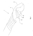
Fig. 1 : ein Beispiel eines Fräserwerkzeugs mit zwei Schneiden; -
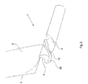
Fig. 2 : ein Beispiel eines Fräserwerkzeugs mit zwei Schneiden in einer Bearbeitungsphase; -
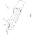
Fig. 3 : ein Beispiel eines weiteren Fräserwerkzeugs; -
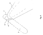
Fig. 4 : ein Beispiel eines Fräserwerkzeugs währen einer ersten Bearbeitungsphase; -
Fig. 5 : ein Beispiel eines Fräserwerkzeugs nach der ersten Bearbeitungsphase; -
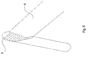
Fig. 6 : ein Beispiel eines Fräserwerkzeugs in einer weiteren Bearbeitungsphase; -
Fig. 7 : ein Beispiel eines Fräserwerkzeugs nach der weiteren Bearbeitungsphase; -
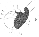
Fig. 8 : ein Beispiel eines Fräserwerkzeugs, in das ein zweiter Spanbereich eingearbeitet wird; -
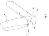
Fig. 9 : ein Beispiel eines Fräserwerkzeugs, dessen zweiter Spanbereich weiter bearbeitet wird; -
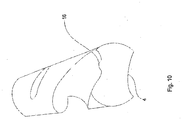
Fig. 10 : ein Beispiel eines Fräserwerkzeugs mit einem speziell bearbeiteten Spanbereich; -
Fig. 11 : ein Beispiel eines Fräserwerkzeugs in dreidimensionaler Darstellung; -
Fig. 12 : ein Beispiel eines Fräserwerkzeugs in einem Beartieitungszustand; und -
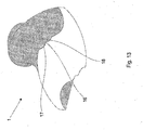
Fig. 13 : ein Beispiel eines weiteren Fräserwerkzeugs in dreidimensionaler Darstellung.
-
Fig. 1 an example of a two-cutter cutter tool; -
Fig. 2 : an example of a milling cutter with two cutting edges in one working phase; -
Fig. 3 an example of another cutter tool; -
Fig. 4 : an example of a milling cutter tool during a first processing phase; -
Fig. 5 an example of a milling cutter tool after the first processing phase; -
Fig. 6 an example of a milling cutter tool in a further processing phase; -
Fig. 7 an example of a milling cutter tool after the further processing phase; -
Fig. 8 an example of a milling tool, in which a second chip area is incorporated; -
Fig. 9 an example of a milling cutter whose second chip area is further processed; -
Fig. 10 an example of a milling cutter tool with a specially machined chip area; -
Fig. 11 : an example of a milling cutter tool in three-dimensional representation; -
Fig. 12 an example of a cutter tool in a Bietieitungszustand; and -
Fig. 13 : an example of another cutter tool in three-dimensional representation.
In
Die Schneide 5 bildet einen Winkel gegenüber der Umfangsfläche aus. Dieser Winkel kann bei mehreren Schneiden gleich oder verschieden sein.The
In
In
In
In
Sämtliche in den Anmeldungsunterlagen offenbarten Merkmale werden als erfindungswesentlich beansprucht, sofern sie einzeln oder in Kombination gegenüber dem Stand der Technik neu sind.All disclosed in the application documents features are claimed as essential to the invention, provided they are new individually or in combination over the prior art.
- 1 : Fräserwerkzeug1: cutter tool
- 2 : Grundkörper2: basic body
- 3 : Bearbeitungswerkzeug3: Editing tool
- 4 : Spanaufnahmebereich4: chip receiving area
- 5 : Schneide5: cutting edge
- 6 : Rotationsachse6: rotation axis
- 7 : erster Kurvenanteil7: first curve part
- 8 : weiteres Bearbeitungswerkzeug8: further processing tool
- 9 : Kante9: edge
- 10 : Vergrößerung des Spanaufnahmebereichs10: Enlargement of the chip removal area
- 11 : Übergang11: transition
- 12 : weiterer Spanaufnahmebereich12: further chip removal area
- 13 : Kante13: edge
- 14 : zweiter Kurvenanteil14: second corner part
- 15a, 15b : Kurvenzentrum15a, 15b: Curve center
- 16 : Erhebung16: survey
- 17, 18 : Rillen17, 18: grooves
- 20 : Stirnseite20: front side
- 21 : Umfangsfläche21: peripheral surface
- 50 : zweite Schneide50: second cutting edge
Claims (9)
- Milling cutter (1) for machining plastics bodies having a main body (2) in the form of a body of revolution, on which at least a first and a second machining portion (5, 50) each extending helically at least in part about an axis of rotation (6) are formed, the machining portions (5, 50) being able to be brought into contact with the plastics body for milling and each comprising chip-receiving regions (4, 12), which adjoin said machining portions and are at a distance from one another, for taking away the removed material, the first chip-receiving region (4) extending further in the circumferential direction than the second chip-receiving region (12) many times over, that is to say by more than four times, in order to take a pressure acting on the milling cutter (1) during milling from the cutting edge of the milling cutter through the second machining portion (50),
characterised in that
at least one of the chip-receiving regions (4, 12) next to the machining portion (5, 50) is delimited by an additional edge (9) which is machined at least in part, the additional edge (9) which is machined at least in part forming an enlarged region (10) of at least the first chip-receiving region (4) on one side, and a new body edge (13) on the other side, wherein the two edges which limit the first chip-receiving region (4) with respect to a circumferential surface of the main body (2) are further spaced apart than the edges which limit the second chip-receiving region (12) with respect to the circumferential surface of the main body (2), wherein the second machining portion (50) has a flute depth which is 60-70 % lower than the flute depth of the first machining portion (5). - Milling cutter (1) according to claim 1,
characterised in that
the edge (9) is abraded at least in part over at least a third, preferably half, and more preferably two thirds of the length of the machining portions (5, 50). - Milling cutter (1) according to either claim 1 or claim 2,
characterised in that
a large number of first and/or second chip-receiving regions (4, 12) are formed on the main body (2). - Milling cutter (1) according to at least one of the preceding claims,
characterised in that
the milling cutter (1) has an end face (20) in the region of the machining portion (5, 50), which face is designed to be inclined at least in some portions relative to a plane extending at a right angle to the axis of rotation (6). - Milling cutter (1) according to claim 4,
characterised in that
individual portions of the inclined end face (20) are configured to be flat or curved and extend in the direction of or counter to the longitudinal direction of the main body (2). - Milling cutter (1) according to at least one of the preceding claims,
characterised in that
at least one of the chip-receiving regions (4, 12) has a curved shape which is different from a circular arc portion. - Milling cutter (1) according to at least one of the preceding claims,
characterised in that
the ratio of the width of the first chip-receiving region (4) to the depth of the first chip-receiving region (4) is greater than the ratio of the width of the second chip-receiving region (12) to the depth of the second chip-receiving region (12). - Milling cutter (1) according to at least one of the preceding claims,
characterised in that
the main body (2) has a shank portion having a greater diameter than that of the machining portion. - Milling cutter (1) according to at least one of the preceding claims,
characterised in that
the milling material consists at least in some portions of at least one of the materials selected from the group at least consisting of high speed steel (HSS), carbide, cermet and/or the like.
Priority Applications (1)
| Application Number | Priority Date | Filing Date | Title |
|---|---|---|---|
| PL11165410T PL2388095T5 (en) | 2010-05-21 | 2011-05-10 | Milling-cutter |
Applications Claiming Priority (2)
| Application Number | Priority Date | Filing Date | Title |
|---|---|---|---|
| DE102010022189 | 2010-05-21 | ||
| DE102010027496A DE102010027496B4 (en) | 2010-05-21 | 2010-07-16 | milling tool |
Publications (3)
| Publication Number | Publication Date |
|---|---|
| EP2388095A1 EP2388095A1 (en) | 2011-11-23 |
| EP2388095B1 EP2388095B1 (en) | 2014-09-03 |
| EP2388095B2 true EP2388095B2 (en) | 2018-04-18 |
Family
ID=44230104
Family Applications (1)
| Application Number | Title | Priority Date | Filing Date |
|---|---|---|---|
| EP11165410.9A Not-in-force EP2388095B2 (en) | 2010-05-21 | 2011-05-10 | Milling-cutter |
Country Status (3)
| Country | Link |
|---|---|
| EP (1) | EP2388095B2 (en) |
| DE (1) | DE102010027496B4 (en) |
| PL (1) | PL2388095T5 (en) |
Families Citing this family (1)
| Publication number | Priority date | Publication date | Assignee | Title |
|---|---|---|---|---|
| DE102010033106B4 (en) * | 2010-05-21 | 2013-11-07 | Rudolf Wendling | milling tool |
Citations (2)
| Publication number | Priority date | Publication date | Assignee | Title |
|---|---|---|---|---|
| DE3742942C1 (en) † | 1987-12-18 | 1988-12-08 | Rolf Klenk Gmbh & Co Kg | Milling tool for roughing and smoothing workpieces |
| US20020090273A1 (en) † | 2001-01-10 | 2002-07-11 | Serwa Ronald K. | Roughing and finishing rotary tool apparatus and method |
Family Cites Families (9)
| Publication number | Priority date | Publication date | Assignee | Title |
|---|---|---|---|---|
| DE3308478A1 (en) * | 1982-03-17 | 1983-09-29 | Uwe 7717 Immendingen Reich | Shank-type cutter |
| DE3623176A1 (en) * | 1986-07-10 | 1988-01-28 | Kwo Werkzeuge Gmbh | Method for the production of a groove milling cutter and groove milling cutter produced by this method |
| JPH06320323A (en) * | 1993-05-19 | 1994-11-22 | Toshiba Tungaloy Co Ltd | Cutting tool |
| IL131119A0 (en) * | 1999-07-26 | 2001-01-28 | Hanita Metal Works Ltd | Milling cutter |
| JP2006150572A (en) * | 2004-12-01 | 2006-06-15 | Osg Corp | Boron doped diamond coating film, and diamond coated cutting tool |
| DE102005002698B4 (en) * | 2005-01-19 | 2007-06-21 | Franken GmbH + Co KG Fabrik für Präzisionswerkzeuge | milling tool |
| DE102005020513B3 (en) * | 2005-04-29 | 2006-09-14 | Näpflin, Schleiftechnik AG | One-piece shaft milling tool for machining sides and edges of boards has a further cure of cutter running parallel to longitudinal axis of milling head in its central region |
| DE202006014089U1 (en) * | 2006-09-11 | 2007-01-11 | Speed Tiger Precision Technology Co., Ltd. | Milling or router tool has two cutting edges feeding two parallel spiral grooves for removal of swarf particles |
| EP2093003A1 (en) * | 2008-02-20 | 2009-08-26 | Fraisa Holding AG | Full machining tool |
-
2010
- 2010-07-16 DE DE102010027496A patent/DE102010027496B4/en not_active Revoked
-
2011
- 2011-05-10 PL PL11165410T patent/PL2388095T5/en unknown
- 2011-05-10 EP EP11165410.9A patent/EP2388095B2/en not_active Not-in-force
Patent Citations (2)
| Publication number | Priority date | Publication date | Assignee | Title |
|---|---|---|---|---|
| DE3742942C1 (en) † | 1987-12-18 | 1988-12-08 | Rolf Klenk Gmbh & Co Kg | Milling tool for roughing and smoothing workpieces |
| US20020090273A1 (en) † | 2001-01-10 | 2002-07-11 | Serwa Ronald K. | Roughing and finishing rotary tool apparatus and method |
Also Published As
| Publication number | Publication date |
|---|---|
| PL2388095T3 (en) | 2015-04-30 |
| PL2388095T5 (en) | 2018-08-31 |
| DE102010027496B4 (en) | 2013-08-08 |
| EP2388095A1 (en) | 2011-11-23 |
| DE102010027496A1 (en) | 2011-11-24 |
| EP2388095B1 (en) | 2014-09-03 |
Similar Documents
| Publication | Publication Date | Title |
|---|---|---|
| EP0937528B1 (en) | Reaming tool and its manufactoring method | |
| EP1864737B1 (en) | Tool for chip-removal | |
| EP2403673B2 (en) | End mill cutter | |
| EP3758876B1 (en) | Chamfering tool, chamfering system, gear-cutting machine and method for chamfering toothings | |
| WO2016020047A1 (en) | Milling tool | |
| EP2848342B1 (en) | Solid milling tool for machining rotating materials | |
| EP3132875B1 (en) | Milling tool | |
| EP2929966B1 (en) | Solid milling tool for machining of materials | |
| DE19824212B4 (en) | Carbide ball nose end mill | |
| EP3743234B1 (en) | Milling tool | |
| EP2916985B1 (en) | Annular tool for machining a workpiece | |
| EP0485546B1 (en) | Cutting insert for tools | |
| WO2017198265A1 (en) | End mill | |
| DE102005058536B4 (en) | Cutting tool system, in particular for splining bevel gears in the single-part method | |
| EP2388095B2 (en) | Milling-cutter | |
| DE102016109130B4 (en) | End mills | |
| DE202017103021U1 (en) | End mills | |
| DE202017103022U1 (en) | End mills | |
| EP1954434A1 (en) | Milling cutter head | |
| DE202016102635U1 (en) | End mills | |
| DE102010033106B4 (en) | milling tool | |
| EP1577060B1 (en) | Notching tool | |
| EP4015123A1 (en) | Solid milling tool for machining rotating materials | |
| EP2388096A1 (en) | Milling-cutter | |
| EP3272447A1 (en) | Milling tool |
Legal Events
| Date | Code | Title | Description |
|---|---|---|---|
| AK | Designated contracting states |
Kind code of ref document: A1 Designated state(s): AL AT BE BG CH CY CZ DE DK EE ES FI FR GB GR HR HU IE IS IT LI LT LU LV MC MK MT NL NO PL PT RO RS SE SI SK SM TR |
|
| AX | Request for extension of the european patent |
Extension state: BA ME |
|
| PUAI | Public reference made under article 153(3) epc to a published international application that has entered the european phase |
Free format text: ORIGINAL CODE: 0009012 |
|
| 17P | Request for examination filed |
Effective date: 20120420 |
|
| 17Q | First examination report despatched |
Effective date: 20130408 |
|
| GRAP | Despatch of communication of intention to grant a patent |
Free format text: ORIGINAL CODE: EPIDOSNIGR1 |
|
| INTG | Intention to grant announced |
Effective date: 20140429 |
|
| GRAS | Grant fee paid |
Free format text: ORIGINAL CODE: EPIDOSNIGR3 |
|
| GRAA | (expected) grant |
Free format text: ORIGINAL CODE: 0009210 |
|
| AK | Designated contracting states |
Kind code of ref document: B1 Designated state(s): AL AT BE BG CH CY CZ DE DK EE ES FI FR GB GR HR HU IE IS IT LI LT LU LV MC MK MT NL NO PL PT RO RS SE SI SK SM TR |
|
| REG | Reference to a national code |
Ref country code: GB Ref legal event code: FG4D Free format text: NOT ENGLISH |
|
| REG | Reference to a national code |
Ref country code: CH Ref legal event code: EP Ref country code: AT Ref legal event code: REF Ref document number: 685292 Country of ref document: AT Kind code of ref document: T Effective date: 20140915 |
|
| REG | Reference to a national code |
Ref country code: IE Ref legal event code: FG4D Free format text: LANGUAGE OF EP DOCUMENT: GERMAN |
|
| REG | Reference to a national code |
Ref country code: DE Ref legal event code: R096 Ref document number: 502011004245 Country of ref document: DE Effective date: 20141016 |
|
| PG25 | Lapsed in a contracting state [announced via postgrant information from national office to epo] |
Ref country code: LT Free format text: LAPSE BECAUSE OF FAILURE TO SUBMIT A TRANSLATION OF THE DESCRIPTION OR TO PAY THE FEE WITHIN THE PRESCRIBED TIME-LIMIT Effective date: 20140903 Ref country code: GR Free format text: LAPSE BECAUSE OF FAILURE TO SUBMIT A TRANSLATION OF THE DESCRIPTION OR TO PAY THE FEE WITHIN THE PRESCRIBED TIME-LIMIT Effective date: 20141204 Ref country code: ES Free format text: LAPSE BECAUSE OF FAILURE TO SUBMIT A TRANSLATION OF THE DESCRIPTION OR TO PAY THE FEE WITHIN THE PRESCRIBED TIME-LIMIT Effective date: 20140903 Ref country code: SE Free format text: LAPSE BECAUSE OF FAILURE TO SUBMIT A TRANSLATION OF THE DESCRIPTION OR TO PAY THE FEE WITHIN THE PRESCRIBED TIME-LIMIT Effective date: 20140903 Ref country code: FI Free format text: LAPSE BECAUSE OF FAILURE TO SUBMIT A TRANSLATION OF THE DESCRIPTION OR TO PAY THE FEE WITHIN THE PRESCRIBED TIME-LIMIT Effective date: 20140903 Ref country code: NO Free format text: LAPSE BECAUSE OF FAILURE TO SUBMIT A TRANSLATION OF THE DESCRIPTION OR TO PAY THE FEE WITHIN THE PRESCRIBED TIME-LIMIT Effective date: 20141203 |
|
| REG | Reference to a national code |
Ref country code: SK Ref legal event code: T3 Ref document number: E 17527 Country of ref document: SK |
|
| REG | Reference to a national code |
Ref country code: NL Ref legal event code: VDEP Effective date: 20140903 |
|
| REG | Reference to a national code |
Ref country code: LT Ref legal event code: MG4D Ref country code: DE Ref legal event code: R026 Ref document number: 502011004245 Country of ref document: DE |
|
| PG25 | Lapsed in a contracting state [announced via postgrant information from national office to epo] |
Ref country code: HR Free format text: LAPSE BECAUSE OF FAILURE TO SUBMIT A TRANSLATION OF THE DESCRIPTION OR TO PAY THE FEE WITHIN THE PRESCRIBED TIME-LIMIT Effective date: 20140903 Ref country code: LV Free format text: LAPSE BECAUSE OF FAILURE TO SUBMIT A TRANSLATION OF THE DESCRIPTION OR TO PAY THE FEE WITHIN THE PRESCRIBED TIME-LIMIT Effective date: 20140903 Ref country code: CY Free format text: LAPSE BECAUSE OF FAILURE TO SUBMIT A TRANSLATION OF THE DESCRIPTION OR TO PAY THE FEE WITHIN THE PRESCRIBED TIME-LIMIT Effective date: 20140903 Ref country code: RS Free format text: LAPSE BECAUSE OF FAILURE TO SUBMIT A TRANSLATION OF THE DESCRIPTION OR TO PAY THE FEE WITHIN THE PRESCRIBED TIME-LIMIT Effective date: 20140903 |
|
| PLBI | Opposition filed |
Free format text: ORIGINAL CODE: 0009260 |
|
| PG25 | Lapsed in a contracting state [announced via postgrant information from national office to epo] |
Ref country code: NL Free format text: LAPSE BECAUSE OF FAILURE TO SUBMIT A TRANSLATION OF THE DESCRIPTION OR TO PAY THE FEE WITHIN THE PRESCRIBED TIME-LIMIT Effective date: 20140903 |
|
| 26 | Opposition filed |
Opponent name: HUFSCHMIED ZERSPANUNGSSYSTEME GMBH Effective date: 20150225 |
|
| PG25 | Lapsed in a contracting state [announced via postgrant information from national office to epo] |
Ref country code: PT Free format text: LAPSE BECAUSE OF FAILURE TO SUBMIT A TRANSLATION OF THE DESCRIPTION OR TO PAY THE FEE WITHIN THE PRESCRIBED TIME-LIMIT Effective date: 20150105 Ref country code: IS Free format text: LAPSE BECAUSE OF FAILURE TO SUBMIT A TRANSLATION OF THE DESCRIPTION OR TO PAY THE FEE WITHIN THE PRESCRIBED TIME-LIMIT Effective date: 20150103 Ref country code: RO Free format text: LAPSE BECAUSE OF FAILURE TO SUBMIT A TRANSLATION OF THE DESCRIPTION OR TO PAY THE FEE WITHIN THE PRESCRIBED TIME-LIMIT Effective date: 20140903 Ref country code: EE Free format text: LAPSE BECAUSE OF FAILURE TO SUBMIT A TRANSLATION OF THE DESCRIPTION OR TO PAY THE FEE WITHIN THE PRESCRIBED TIME-LIMIT Effective date: 20140903 |
|
| REG | Reference to a national code |
Ref country code: PL Ref legal event code: T3 |
|
| REG | Reference to a national code |
Ref country code: DE Ref legal event code: R026 Ref document number: 502011004245 Country of ref document: DE Effective date: 20150225 |
|
| PLAX | Notice of opposition and request to file observation + time limit sent |
Free format text: ORIGINAL CODE: EPIDOSNOBS2 |
|
| PG25 | Lapsed in a contracting state [announced via postgrant information from national office to epo] |
Ref country code: DK Free format text: LAPSE BECAUSE OF FAILURE TO SUBMIT A TRANSLATION OF THE DESCRIPTION OR TO PAY THE FEE WITHIN THE PRESCRIBED TIME-LIMIT Effective date: 20140903 |
|
| PLAF | Information modified related to communication of a notice of opposition and request to file observations + time limit |
Free format text: ORIGINAL CODE: EPIDOSCOBS2 |
|
| PG25 | Lapsed in a contracting state [announced via postgrant information from national office to epo] |
Ref country code: IT Free format text: LAPSE BECAUSE OF FAILURE TO SUBMIT A TRANSLATION OF THE DESCRIPTION OR TO PAY THE FEE WITHIN THE PRESCRIBED TIME-LIMIT Effective date: 20140903 |
|
| PLBB | Reply of patent proprietor to notice(s) of opposition received |
Free format text: ORIGINAL CODE: EPIDOSNOBS3 |
|
| PG25 | Lapsed in a contracting state [announced via postgrant information from national office to epo] |
Ref country code: SI Free format text: LAPSE BECAUSE OF FAILURE TO SUBMIT A TRANSLATION OF THE DESCRIPTION OR TO PAY THE FEE WITHIN THE PRESCRIBED TIME-LIMIT Effective date: 20140903 |
|
| REG | Reference to a national code |
Ref country code: CH Ref legal event code: PL |
|
| GBPC | Gb: european patent ceased through non-payment of renewal fee |
Effective date: 20150510 |
|
| PG25 | Lapsed in a contracting state [announced via postgrant information from national office to epo] |
Ref country code: LU Free format text: LAPSE BECAUSE OF FAILURE TO SUBMIT A TRANSLATION OF THE DESCRIPTION OR TO PAY THE FEE WITHIN THE PRESCRIBED TIME-LIMIT Effective date: 20150510 Ref country code: MC Free format text: LAPSE BECAUSE OF FAILURE TO SUBMIT A TRANSLATION OF THE DESCRIPTION OR TO PAY THE FEE WITHIN THE PRESCRIBED TIME-LIMIT Effective date: 20140903 Ref country code: CH Free format text: LAPSE BECAUSE OF NON-PAYMENT OF DUE FEES Effective date: 20150531 Ref country code: LI Free format text: LAPSE BECAUSE OF NON-PAYMENT OF DUE FEES Effective date: 20150531 |
|
| REG | Reference to a national code |
Ref country code: IE Ref legal event code: MM4A |
|
| REG | Reference to a national code |
Ref country code: FR Ref legal event code: ST Effective date: 20160129 |
|
| PG25 | Lapsed in a contracting state [announced via postgrant information from national office to epo] |
Ref country code: GB Free format text: LAPSE BECAUSE OF NON-PAYMENT OF DUE FEES Effective date: 20150510 Ref country code: IE Free format text: LAPSE BECAUSE OF NON-PAYMENT OF DUE FEES Effective date: 20150510 |
|
| PG25 | Lapsed in a contracting state [announced via postgrant information from national office to epo] |
Ref country code: FR Free format text: LAPSE BECAUSE OF NON-PAYMENT OF DUE FEES Effective date: 20150601 |
|
| PG25 | Lapsed in a contracting state [announced via postgrant information from national office to epo] |
Ref country code: MT Free format text: LAPSE BECAUSE OF FAILURE TO SUBMIT A TRANSLATION OF THE DESCRIPTION OR TO PAY THE FEE WITHIN THE PRESCRIBED TIME-LIMIT Effective date: 20140903 |
|
| PG25 | Lapsed in a contracting state [announced via postgrant information from national office to epo] |
Ref country code: HU Free format text: LAPSE BECAUSE OF FAILURE TO SUBMIT A TRANSLATION OF THE DESCRIPTION OR TO PAY THE FEE WITHIN THE PRESCRIBED TIME-LIMIT; INVALID AB INITIO Effective date: 20110510 Ref country code: BG Free format text: LAPSE BECAUSE OF FAILURE TO SUBMIT A TRANSLATION OF THE DESCRIPTION OR TO PAY THE FEE WITHIN THE PRESCRIBED TIME-LIMIT Effective date: 20140903 Ref country code: SM Free format text: LAPSE BECAUSE OF FAILURE TO SUBMIT A TRANSLATION OF THE DESCRIPTION OR TO PAY THE FEE WITHIN THE PRESCRIBED TIME-LIMIT Effective date: 20140903 |
|
| REG | Reference to a national code |
Ref country code: AT Ref legal event code: MM01 Ref document number: 685292 Country of ref document: AT Kind code of ref document: T Effective date: 20160510 |
|
| PG25 | Lapsed in a contracting state [announced via postgrant information from national office to epo] |
Ref country code: BE Free format text: LAPSE BECAUSE OF NON-PAYMENT OF DUE FEES Effective date: 20150531 |
|
| PG25 | Lapsed in a contracting state [announced via postgrant information from national office to epo] |
Ref country code: TR Free format text: LAPSE BECAUSE OF FAILURE TO SUBMIT A TRANSLATION OF THE DESCRIPTION OR TO PAY THE FEE WITHIN THE PRESCRIBED TIME-LIMIT Effective date: 20140903 Ref country code: AT Free format text: LAPSE BECAUSE OF NON-PAYMENT OF DUE FEES Effective date: 20160510 |
|
| PUAH | Patent maintained in amended form |
Free format text: ORIGINAL CODE: 0009272 |
|
| STAA | Information on the status of an ep patent application or granted ep patent |
Free format text: STATUS: PATENT MAINTAINED AS AMENDED |
|
| 27A | Patent maintained in amended form |
Effective date: 20180418 |
|
| AK | Designated contracting states |
Kind code of ref document: B2 Designated state(s): AL AT BE BG CH CY CZ DE DK EE ES FI FR GB GR HR HU IE IS IT LI LT LU LV MC MK MT NL NO PL PT RO RS SE SI SK SM TR |
|
| REG | Reference to a national code |
Ref country code: DE Ref legal event code: R102 Ref document number: 502011004245 Country of ref document: DE |
|
| PG25 | Lapsed in a contracting state [announced via postgrant information from national office to epo] |
Ref country code: MK Free format text: LAPSE BECAUSE OF FAILURE TO SUBMIT A TRANSLATION OF THE DESCRIPTION OR TO PAY THE FEE WITHIN THE PRESCRIBED TIME-LIMIT Effective date: 20140903 |
|
| PGFP | Annual fee paid to national office [announced via postgrant information from national office to epo] |
Ref country code: CZ Payment date: 20180502 Year of fee payment: 8 Ref country code: DE Payment date: 20180517 Year of fee payment: 8 Ref country code: SK Payment date: 20180427 Year of fee payment: 8 |
|
| PGFP | Annual fee paid to national office [announced via postgrant information from national office to epo] |
Ref country code: PL Payment date: 20180507 Year of fee payment: 8 |
|
| REG | Reference to a national code |
Ref country code: SK Ref legal event code: T5 Ref document number: E 17527 Country of ref document: SK |
|
| PG25 | Lapsed in a contracting state [announced via postgrant information from national office to epo] |
Ref country code: AL Free format text: LAPSE BECAUSE OF FAILURE TO SUBMIT A TRANSLATION OF THE DESCRIPTION OR TO PAY THE FEE WITHIN THE PRESCRIBED TIME-LIMIT Effective date: 20140903 |
|
| REG | Reference to a national code |
Ref country code: DE Ref legal event code: R119 Ref document number: 502011004245 Country of ref document: DE |
|
| PG25 | Lapsed in a contracting state [announced via postgrant information from national office to epo] |
Ref country code: CZ Free format text: LAPSE BECAUSE OF NON-PAYMENT OF DUE FEES Effective date: 20190510 Ref country code: SK Free format text: LAPSE BECAUSE OF NON-PAYMENT OF DUE FEES Effective date: 20190510 |
|
| REG | Reference to a national code |
Ref country code: SK Ref legal event code: MM4A Ref document number: E 17527 Country of ref document: SK Effective date: 20190510 |
|
| PG25 | Lapsed in a contracting state [announced via postgrant information from national office to epo] |
Ref country code: DE Free format text: LAPSE BECAUSE OF NON-PAYMENT OF DUE FEES Effective date: 20191203 |
|
| PG25 | Lapsed in a contracting state [announced via postgrant information from national office to epo] |
Ref country code: PL Free format text: LAPSE BECAUSE OF NON-PAYMENT OF DUE FEES Effective date: 20190510 |