EP2387675B1 - Getriebegehäuse - Google Patents
Getriebegehäuse Download PDFInfo
- Publication number
- EP2387675B1 EP2387675B1 EP10700944.1A EP10700944A EP2387675B1 EP 2387675 B1 EP2387675 B1 EP 2387675B1 EP 10700944 A EP10700944 A EP 10700944A EP 2387675 B1 EP2387675 B1 EP 2387675B1
- Authority
- EP
- European Patent Office
- Prior art keywords
- transmission casing
- sections
- section
- transmission
- gear housing
- Prior art date
- Legal status (The legal status is an assumption and is not a legal conclusion. Google has not performed a legal analysis and makes no representation as to the accuracy of the status listed.)
- Active
Links
Images


Classifications
-
- F—MECHANICAL ENGINEERING; LIGHTING; HEATING; WEAPONS; BLASTING
- F16—ENGINEERING ELEMENTS AND UNITS; GENERAL MEASURES FOR PRODUCING AND MAINTAINING EFFECTIVE FUNCTIONING OF MACHINES OR INSTALLATIONS; THERMAL INSULATION IN GENERAL
- F16H—GEARING
- F16H57/00—General details of gearing
- F16H57/02—Gearboxes; Mounting gearing therein
- F16H57/032—Gearboxes; Mounting gearing therein characterised by the materials used
-
- F—MECHANICAL ENGINEERING; LIGHTING; HEATING; WEAPONS; BLASTING
- F16—ENGINEERING ELEMENTS AND UNITS; GENERAL MEASURES FOR PRODUCING AND MAINTAINING EFFECTIVE FUNCTIONING OF MACHINES OR INSTALLATIONS; THERMAL INSULATION IN GENERAL
- F16H—GEARING
- F16H57/00—General details of gearing
- F16H57/02—Gearboxes; Mounting gearing therein
- F16H57/038—Gearboxes for accommodating bevel gears
-
- H—ELECTRICITY
- H02—GENERATION; CONVERSION OR DISTRIBUTION OF ELECTRIC POWER
- H02K—DYNAMO-ELECTRIC MACHINES
- H02K5/00—Casings; Enclosures; Supports
- H02K5/04—Casings or enclosures characterised by the shape, form or construction thereof
- H02K5/06—Cast metal casings
Definitions
- the invention relates to a transmission housing for a bevel gear.
- the DE 201 06 655 U1 discloses a cleanroom geared motor having a motor portion and a gear portion joined together to form a unit, the unit having a smooth surface.
- the invention has the object of developing a transmission housing.
- the object is achieved in the transmission housing according to the features indicated in claim 1 and in the method with the features of claim 12.
- the gear housing for a bevel gear has a surface which consists of sections and cultivated areas such that each section adjacent to at least two cultivated surfaces and each section is continuously convexly curved along at least one surface curve, wherein the surface curve is the intersection of an imaginary normal plane associated with a point of the section with the respective section.
- the gear housing for a bevel gear has a surface which consists of sections and cultivated areas, that is, in particular only sections and cultivated surfaces, wherein the sections are convexly curved in at least one direction.
- the surface curve runs along one direction.
- the normal plane is perpendicular to a tangent vector of a point on the surface or section.
- the sections have a radius of curvature of greater than about 3 mm, in particular greater than about 6 mm.
- the advantage here is that liquids run well on the surface of the gear housing and impurities are easily removed without drain channels must be provided. In addition, these curves facilitate removal from the mold in the manufacture of the gear housing as a casting.
- the cultivation surfaces which have a bore, perpendicular or parallel to each other and in the installed state of the gear housing or a corresponding gear, the cropping areas are covered by appropriate surfaces mounted devices and / or covered by a matching cover.
- a surface of the cover elements facing away from the gear housing is formed corresponding to the sections or the sections and planes.
- the regions and thus the surface comprise an intermediate surface which is convex in a first direction and concavely or convexly curved in a second direction, in particular the first direction is approximately perpendicular to perpendicular to the second direction.
- the transmission housing has an output side, in which a first and second continuous recess are incorporated, wherein the first and second recesses form a common end face, which constitutes a first mounting surface.
- the gear housing made of stainless steel in particular made of stainless steel GX5CrNI19-10.
- the advantage here is that the gear housing is easy to clean and the surface can withstand even more aggressive cleaning agents.
- the surface is coated with a non-corrosive and / or non-stick coating, in particular a polymer.
- a non-corrosive and / or non-stick coating in particular a polymer.
- the surface has an arithmetic mean roughness Ra between about 0.8 microns and about 6.0 microns, preferably between about 2.5 microns and about 3.5 microns.
- the advantage here is that impurities and bacteria have a smaller contact surface to the surface of the gear housing without sinking into depressions on the surface. This results in a lower adhesive force than a smooth surface and the gear housing is easier to clean.
- the transmission housing has a reinforcement on an inner surface.
- the advantage here is that the surface of the gear housing has no contours or projections on which impurities stick better or are poorly flushable.
- gear housing is cast from stainless steel and then the gear housing is ground and / or electropolished.
- the advantage here is that a conventional manufacturing process can be used, which is refined with an inventive process step.
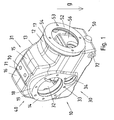
- FIG. 1 shows a transmission housing 10 according to the invention for a bevel gear in plan view. Due to the desired functionality of a bevel gear some design features for the gear housing 10 are given.
- the transmission housing 10 has a input side 50 and an output side.
- the transmission housing 10 has a first output side 30 and a second output side 31 opposite the first output side 30.
- the first and second output side 30, 31 are each in a mutually parallel output plane, which are perpendicular to a Eintriebsebene, in which the Eintriebsseite 50 is located.
- the transmission housing 10 has a surface consisting of sections, cultivated areas and planes.
- Consist of is meant here that the surface has only sections, cultivated areas and levels.
- the levels are in the context of the customary for the production as casting or with cutting techniques un-curved, ie plane planes.
- the planes are arranged such that, when using the gear housing 10 in a plant, the levels at each installation position of the gear housing 10 to an imaginary plane E whose normal vector is collinear to gravity g, an angle ⁇ include whose amount is greater than or equal to three degrees. Exemplary is in FIG. 3 the angle ⁇ between a second plane 16 and the imaginary plane E drawn.
- first recess 32 and a second recess 34 are introduced in the first output side 30, a first recess 32 and a second recess 34 are introduced.
- the first and second recesses 32, 34 are formed in a circle with different diameters.
- the first recess 32 has a larger diameter and is used for mounting an output shaft.
- an output shaft designed as a solid shaft the solid shaft projects out of the first recess 32.
- a shaft of a device to be driven is introduced into the hollow shaft and thus into the first recess 32.
- the second recess 34 serves to mount an intermediate shaft on which, for example, a ring gear of a bevel gear stage can be mounted.
- a first mounting surface 14 forms a common end face of the first and second recesses 32, 34.
- first hole pattern 33 is for example used to attach the gear housing in various discrete mounting positions on a device to be driven.
- the input side 50 has a circular opening 56 with a third mounting surface 52 as an end face. Around the circular opening 56 bores 52 are arranged in the third mounting surface, which result in a second hole pattern 53.
- the second hole pattern 53 is used to attach a motor or a motor adapter to the transmission housing 10.
- the second output side is designed analogous to the first output side.
- the sections are spanned by a respective first and second direction.
- the sections are convexly curved at least along a respective first direction, that is to say a first surface curve is convexly curved.
- the sections are advantageously also convexly curved, that is, a second surface curve is also convex. In certain sections, however, concave curvatures along a first or second direction are unavoidable.
- a normal plane can be found through the point which, as a section with the associated section, forms a convexly curved surface curve. "only convexly curved” is equivalent to “continuously convexly curved”. The normal plane intersects the corresponding section in the point vertically.
- Each section adjoins at least two acreages or levels. This means that the sections each adjoin at least two cultivable areas or two levels, or one acreage and one level. However, the sections may also adjoin several cultivated areas or levels.
- Each section is convexly curved along at least one surface curve, the surface curve being the intersection of an imaginary normal plane associated with a point of the section with the respective section.
- the normal plane intersects the surface at the point perpendicular.
- the normal plane can be rotated in each section so that its section produces a convex surface curve with the section of the surface. This creates a surface curve over the entire section, which is only convexly curved.
- the surface of the gearbox can be divided into sections, levels and planted areas so that the conditions described above for the sections, areas and levels are met. This leads to a bulbous appearance of the transmission housing, since each section is curved along at least one direction outward.
- the sections are convexly curved in each case in a first direction.
- the sections are still divided into areas.
- a first region 12 is convexly curved in a first direction and planar in a second direction perpendicular to the first direction within the manufacturing accuracy.
- Other regions, such as an edge-like region 13 are convex in their first direction and in their second direction Direction also convex.
- the first region 12, the edge-like region 13 and the cylinder jacket surface 17 lie in a section between the third mounting surface and the first plane 15.
- Another region which is formed as an intermediate surface 19 between a cylinder jacket surface region 18 and another region, is convexly curved in a first direction and concavely curved in a second direction, thus forming a saddle surface.
- the intermediate surface 19 revolves around the first and second recesses 32, 34.
- the cylinder jacket surface area 18 and the intermediate surface 19 lie in a further section of the surface between the first mounting surface 14 and the ventilation surface 71.
- FIG. 4 shows an example of an elongated thickening 62 and a semi-circular thickening 64 as a reinforcement on the inner surface 60 of the gear housing 10. This also simplifies a post-treatment of the surface of the gear housing 10th
- the acreage are unrestrained and covered in the installed state of the gear housing 10 by corresponding cover and / or attached devices.
- the sealing elements required between cover element or mounted device and the transmission housing 10 are arranged so that no gaps or covered cavities are formed.
- Only outside edges of the acreage are edges in the true sense, ie edges that are formed in the context of manufacturing capabilities by two abutting abutting surfaces directly.
- the abutment surfaces of the edges are usually formed by a portion of the surface and a cultivated area. Transitions between two sections are at the in FIG. 1 shown embodiment executed as sections.
- the first mounting surface 14 forms a common end face for the first recess 32 and the second recess 34 of the first output side.
- the second output side 31 is carried out accordingly.
- a radius of curvature of about 6mm is advantageous and a radius of curvature of about 3mm is just barely able to drain liquids on the surface and easily remove soiling can. Therefore, in a particularly preferred embodiment, the surface, except for the outer edges of the cultivation surfaces along any direction only curvature radii, which are greater than 3mm, particularly advantageously, the radii of curvature greater than 6mm. In particular, an edge-like region 13 is rounded so that it has the preferred radii of curvature.
- the radius of curvature is defined by the radius of a circle that conforms to the surface. Curvature is the reciprocal of the radius of curvature.
- a plane that is plane in the context of manufacturing accuracy should include an angle greater than 3 degrees to an imaginary plane whose unit vector is collinear with gravity.
- the transmission housing 10 has a first through-bore 70 and a second through-bore 72. These are closed in the assembled state of the transmission by a screw plug or a vent valve. Depending on the mounting position of the transmission, the vent valve in the first through hole 70 or the second through hole 72 can be screwed.
- the first and second through-holes 70, 72 are surrounded by a corresponding mounting surface, such as a venting surface 71.
- FIG. 2 shows as bottom view a foot of the in FIG. 1
- the foot side has a mounting surface as a foot surface 38 and a third plane 35.
- the foot surface 38 serves as a support surface for the transmission housing 10.
- this support surface is not present and the third plane 35 extends almost over the entire length of the foot.
- a mounting side 40 of the transmission housing 10 according to the invention is in FIG. 3 shown in the rear view of the transmission housing 10.
- the mounting opening 46 is used for mounting or introducing the arranged in the gear housing 10 shafts and gears.
- the mounting opening 46 is framed by a second mounting surface 42 having holes with internal thread. At the second mounting surface 42 is in the transmission housing 10 after installation of the transmission in an FIG. 5 shown lid 20 screwed.
- the lid 20 is formed substantially rectangular and closes the mounting hole 46.
- the surface of the lid itself has according to the transmission housing 10 designed sections, levels and mounting surface.
- In the cover mounting holes 76 are executed. Through these mounting holes 76 screws are guided, with which the cover 20 is fixed to the transmission housing 10.
- the screws are designed to fit the in FIG. 5 cover shown counter surfaces for the screws. These counter surfaces thus also form cultivation areas in the sense of the invention.
- a base of the surface of the lid 20 forms a saddle roof surface 44 whose gable divides the surface into two halves along the long side of the rectangle.
- the saddle roof surfaces form an imaginary ground plane of the lid 20 an angle of at least three degrees.
- Attachment surfaces of the lid 20 serve as a support corresponding fastening screws for screwing the cover 20 to the second mounting surface 42.
- the cultivation surfaces can be covered by suitably shaped cover elements such as screw heads or shims, so that the final visible surface in the assembled state only convex or convex at least in one direction Has sections.
- a special mounting surface 74 of the lid 20 protrudes into the saddle roof surface and has a cover bore 73 into which a vent valve or a screw plug can be screwed.
- FIG. 4 shows that in FIG. 1 shown gear housing 10 in section. Reinforcements of the transmission housing 10, which in the prior art usually at the Housing surface are formed, are shifted in the transmission housing 10 according to the invention into the interior of the transmission case 10. On the inside of the gear housing 10, for example, semicircular thickenings 64 or elongated thickenings 62 are formed as reinforcements. Nevertheless, the usual gearing parts and shafts, for example, for a bevel gear with two spur gears and a bevel gear can be installed in the transmission housing according to the invention.
- An in FIG. 6 shown intermediate plate has a substantially egg-shaped base surface, which is substantially congruent with the first mounting surface 14.
- a drilling pattern executed in the intermediate disk corresponds to the first hole pattern 33 around the first recess 32 in the first mounting surface 14.
- the intermediate disk 24 has a recess 75 corresponding to the first recess 32.
- the intermediate disc conceals the second recess 34.
- the second recess is securely closed, without the resulting in the entire surface of the assembled transmission from an externally accessible recess or externally accessible cavity.
- the intermediate disk 24 is executable such that a convex surface is present above the second recess 34.
- the second output side 31 can be covered analogously or by a further cover element, which covers both recesses of the second output side without a remaining opening.
- FIG. 7 shows a torque arm 26 whose surface is designed according to the surface of the transmission housing 10.
- the torque arm 26 has a larger and a smaller approximately annular element 90, 92, which are connected to each other via two legs 94, 96.
- the two legs 94, 96 lying in one plane, are formed on the peripheries of the approximately annular elements 90, 92 and are at an angle to each other, so that the angle to the larger approximately annular element 90 opens.
- the larger approximately annular element 90 has flattened end faces in which a further hole pattern 98 is introduced, which corresponds to the first hole pattern 33.
- the smaller approximately annular element 92 is used to attach the torque arm 26 to a rotationally fixed device.
- first mounting surface 14 or the intermediate disk 24 or the torque arm 26 and the third mounting surface 52 can be attached according to the surface of the gear housing 10 molded flanges. These serve as adapters for connection to corresponding drive means, such as electric motors, or devices to be driven, or clutches, brakes etc.
- the gear housing 10, the washer 24 and the torque arm 26 made of stainless steel in particular made of stainless steel GX5CrNi19-10. Due to the high strength and the reinforcements on the inside of the gear housing can then be dispensed with a vent under suitable operating conditions. Then, the through-holes 70, 72 and the corresponding acreage 71 can be omitted. This also saves the matching cover.
- the geometry of the surface with less concave curvatures is executable. For example, the second plane 16 is then continued in the direction of the input side 50 and forms a continuous plane with the first plane 15.
- Known gearboxes not shown here have on certain cultivated areas, in particular in the Eintriebsseite 50 so-called output pockets.
- the output pockets are usually formed as accessible from the surface, in particular wedge-shaped recesses, for example, in the third mounting surface 52 of the input side 52.
- the output pockets interrupt an edge 54 of the third mounting surface of the input side 50 or deform this edge 54.
- the output pockets are formed in known transmissions from the outside accessible cavities. These cavities are omitted in a preferred embodiment of the invention and an outer edge 54 of the third mounting surface 52 forms an uninterrupted circle.
- the third mounting surface 52 is formed as an end face of the Eintriebsseite for flanging a motor.
- the surface consists only of sections and cultivated areas.
- the sections and cultivated areas are as described above.
- the gear housing 10 is advantageously manufactured as a cast part.
- the surface of the gear housing 10 is then ground and / or electropolished, so that the Surface has an arithmetic mean roughness Ra of between about 0.8 ⁇ m and about 6.0 ⁇ m, preferably between about 2.5 ⁇ m and about 3.5 ⁇ m.
- This has the advantage over smooth surfaces that the dirt particles or other contaminants, such as bacteria, are not completely in contact with the surface. As a result, an adhesion between bacteria or dirt and the surface is reduced and the impurities are easier to remove.
- the surface may additionally be coated with an anti-corrosion layer and / or anti-adhesion layer.
- a polymer such as polytetrafluoroethylene.
- gear housing for a bevel gear is not limited to bevel gear and can also apply to gear housing for other gear.
Landscapes
- Engineering & Computer Science (AREA)
- General Engineering & Computer Science (AREA)
- Mechanical Engineering (AREA)
- General Details Of Gearings (AREA)
Description
- Die Erfindung betrifft ein Getriebegehäuse für ein Kegelradgetriebe.
- Die
DE 201 06 655 U1 offenbart einen Reinraum-Getriebemotor mit einem Motorabschnitt und einem Getriebeabschnitt, die miteinander verbunden sind und eine Baueinheit bilden, wobei die Baueinheit eine glatte Oberfläche aufweist. - Aus der gattungsgemäßen
US 2006/0156861 A1 Ist ein Getriebegehäuse bekannt. - Der Erfindung liegt die Aufgabe zugrunde, ein Getriebegehäuse weiterzubilden.
- Erfindungsgemäß wird die Aufgabe bei dem Getriebegehäuse nach den in Anspruch 1 angegebenen Merkmalen und bei dem Verfahren mit den Merkmalen des Anspruchs 12 gelöst.
- Wichtige Merkmale der Erfindung bei dem Getriebegehäuse für ein Kegelradgetriebe sind, dass das Getriebegehäuse für ein Kegelradgetriebe eine Oberfläche aufweist, welche derart aus Abschnitten und Anbauflächen besteht, dass jeder Abschnitt an mindestens zwei Anbauflächen angrenzt und jeder Abschnitt entlang zumindest einer Oberflächenkurve durchgehend konvex gekrümmt ist, wobei die Oberflächenkurve das Schnittgebilde einer zu einem Punkt des Abschnitts gehörigen gedachten Normalenebene mit dem jeweiligen Abschnitt ist.
- Oder mit anderen Worten, dass das Getriebegehäuse für ein Kegelradgetriebe eine Oberfläche aufweist, welche aus Abschnitten und Anbauflächen besteht, das heißt insbesondere nur Abschnitte und Anbauflächen aufweist, wobei die Abschnitte in zumindest einer Richtung konvex gekrümmt sind. Die Oberflächenkurve läuft entlang einer Richtung. Die Normalenebene steht senkrecht auf einem Tangentenvektor eines Punkles auf der Oberfläche beziehungsweise des Abschnitts.
- Von Vorteil ist dabei, dass Flüssigkeiten an der Oberfläche des Getriebegehäuses gut ablaufen und Verunreinigungen leicht entfernbar sind, ohne dass Abflusskanäle vorgesehen werden müssen.
- Bei einer weiteren Ausführungsform weisen die Abschnitte einen Krümmungsradius von größer als ca. 3 mm insbesondere von größer als ca. 6 mm auf. Von Vorteil ist dabei, dass Flüssigkeiten an der Oberfläche des Getriebegehäuses gut ablaufen und Verunreinigungen leicht entfernbar sind, ohne dass Abflusskanäle vorgesehen werden müssen. Zudem erleichtern diese Krümmungen ein Entformen beim Herstellen des Getriebegehäuses als Gussteil.
- Bei einer weiteren Ausführungsform sind die Anbauflächen, welche eine Bohrung aufweisen, senkrecht oder parallel zueinander und im eingebauten Zustand des Getriebegehäuses bzw. eines korrespondierenden Getriebes sind die Anbauflächen durch entsprechende Flächen angebauter Vorrichtungen und/oder durch ein passendes Abdeckelement abgedeckt. Von Vorteil ist dabei, dass sich das Getriebegehäuse gut in eine Anlage einfügen lässt so dass Flüssigkeiten an der Oberfläche des Getriebegehäuses gut ablaufen und Verunreinigungen leicht entfernbar sind, ohne dass Abflusskanäle vorgesehen werden müssen.
- Bei einer weiteren Ausführungsform ist eine vom Getriebegehäuse abgewandte Oberfläche der Abdeckelemente den Abschnitten beziehungsweise den Abschnitten und Ebenen entsprechend ausgeformt. Von Vorteil ist dabei, dass das Getriebegehäuse gute Reinigungseigenschaften aufweist und trotzdem die Flexibilität eines normalen Getriebegehäuses bietet.
- Bei einer weiteren Ausführungsform umfassen die Bereiche und somit die Oberfläche eine Zwischenoberfläche, welche in einer ersten Richtung konvex und in einer zweiten Richtung konkav oder konvex gekrümmt ist, insbesondere ist die erste Richtung annähernd senkrecht bis senkrecht zur zweiten Richtung. Von Vorteil ist dabei, dass Flüssigkeiten an der Oberfläche des Getriebegehäuses gut ablaufen und Verunreinigungen leicht entfernbar sind.
- Bei einer weiteren Ausführungsform weist das Getriebegehäuse eine Abtriebsseite auf, in welcher eine erste und zweite durchgehende Ausnehmung eingearbeitet sind, wobei die erste und zweite Ausnehmung eine gemeinsame Stirnfläche bilden, welche eine erste Anbaufläche darstellt. Von Vorteil ist dabei, dass die gemeinsame Stirnfläche gut abdeckbar ist und gleichzeitig die zweite Ausnehmung durch eine dafür vorgesehene Abdeckung abdeckbar ist, ohne das kritische Vertiefungen und/oder Hohlräume entstehen.
- Bei einer weiteren Ausführungsform ist das Getriebegehäuse aus Edelstahl insbesondere aus dem Edelstahl GX5CrNI19-10 hergestellt. Von Vorteil ist dabei, dass das Getriebegehäuse leicht zu reinigen ist und die Oberfläche auch aggressiveren Reinigungsmitteln standhält.
- Bei einer weiteren Ausführungsform ist die Oberfläche mit einer nicht korrosiven und/oder antihaftenden Beschichtung insbesondere einem Polymer beschichtet. Von Vorteil ist dabei, dass das Getriebegehäuse leicht zu reinigen ist und die Oberfläche auch aggressiveren Reinigungsmitteln standhält.
- Bei einer weiteren Ausführungsform weist die Oberfläche einen arithmetischen Mittenrauwert Ra zwischen ungefähr 0.8 Mikrometern und ungefähr 6.0 Mikrometern, vorzugsweise zwischen ungefähr 2.5 Mikrometern und ungefähr 3.5 Mikrometern, auf. Von Vorteil ist dabei, dass Verunreinigungen und Bakterien eine kleinere Kontaktfläche zur Oberfläche des Getriebegehäuses aufweisen ohne in Vertiefungen an der Oberfläche zu versinken. Somit ergibt sich eine geringere Adhäsionskraft als bei einer glatten Oberfläche und das Getriebegehäuse ist leichter zu reinigen.
- Bei einer weiteren Ausführungsform weist das Getriebegehäuse an einer Innenfläche eine Verstärkung auf. Von Vorteil ist dabei, dass die Oberfläche des Getriebegehäuses keine Konturen oder Vorsprünge aufweist, an welchen Verunreinigungen besser haften bleiben oder nur schlecht wegspülbar sind.
- Wichtige Merkmale eines Verfahrens zur Herstellung eines Getriebegehäuses sind, dass das Getriebegehäuse aus Edelstahl gegossen wird und anschließend das Getriebegehäuse geschliffen und/oder elektropoliert wird. Von Vorteil ist dabei, dass ein übliches Herstellungsverfahren verwendbar ist, welches mit einem erfinderischen Verfahrensschritt veredelt wird.
- Weitere Vorteile ergeben sich aus den Unteransprüchen. Die Erfindung ist nicht auf die Merkmalskombination der Ansprüche beschränkt. Für den Fachmann ergeben sich weitere sinnvolle Kombinationsmöglichkeiten von Ansprüchen und/oder einzelnen Anspruchsmerkmalen und/oder Merkmalen der Beschreibung und/oder der Figuren, insbesondere aus der Aufgabenstellung und/oder der sich durch Vergleich mit dem Stand der Technik stellenden Aufgabe.
-
- 10
- Getriebegehäuse
- 12
- erster Bereich
- 13
- kantenartiger Bereich
- 14
- erste Anbaufläche
- 15
- erste Ebene
- 16
- zweite Ebene
- 17
- Zylindermantelfläche
- 18
- Zylindermantelflächenbereich
- 19
- Zwischenoberfläche
- 20
- Deckel
- 24
- Zwischenscheibe
- 26
- Drehmomentstütze
- 30
- erste Abtriebsseite
- 31
- zweite Abtriebsseite
- 32
- erste Ausnehmung
- 33
- erstes Bohrbild
- 34
- zweite Ausnehmung
- 35
- dritte Ebene
- 38
- aufliegende Anbaufläche
- 40
- Montageseite
- 42
- zweite Anbaufläche
- 44
- Satteldachfläche
- 46
- Montageöffnung
- 50
- Eintriebsseite
- 52
- dritte Anbaufläche
- 53
- zweites Bohrbild
- 54
- äußere Kante
- 56
- kreisförmige Öffnung
- 60
- Innenfläche
- 62
- längliche Verdickung
- 64
- ringförmige Verdickung
- 70
- erste Durchgangsbohrung
- 71
- Anbaufläche für Entlüftung
- 72
- zweite Durchgangsbohrung
- 73
- Deckelbohrung
- 74
- besondere Anbaufläche des Deckels
- 76
- Montagelöcher
- 90
- größeres annähernd ringförmiges Element
- 92
- kleineres annähernd ringförmiges Element
- 94, 96
- zwei Schenkel
- 98
- weiteres Bohrbild
- Die Erfindung wird nun anhand von Ausführungsbeispielen mit Bezugnahme auf die Zeichnung näher erläutert. Es zeigen rein schematisch:
-
Fig. 1 eine perspektivische Draufsicht auf ein erfindungsgemäßes Getriebegehäuse; -
Fig. 2 eine Unteransicht des inFigur 1 gezeigten Getriebegehäuses; - Flg. 3 eine Rückansicht des in
Figur 1 gezeigten Getriebegehäuses; -
Fig. 4 einen Schnitt durch das inFigur 1 gezeigte Getriebegehäuse; -
Fig. 5 eine perspektivische Draufsicht eines Deckels für das inFigur 1 gezeigte Getriebegehäuse; -
Fig. 6 eine perspektivische Draufsicht einer Zwischenscheibe für das inFigur 1 gezeigte Getriebegehäuse; und -
Fig. 7 eine perspektivische Draufsicht einer Drehmomentstütze für das inFigur 1 gezeigte Getriebegehäuse. -
Figur 1 zeigt ein erfindungsgemäßes Getriebegehäuse 10 für ein Kegelradgetriebe in Draufsicht. Durch die erwünschte Funktionalität eines Kegelradgetriebes sind einige konstruktive Merkmale für das Getriebegehäuse 10 vorgegeben. Insbesondere weist das Getriebegehäuse 10 eine Eintriebsseite 50 und eine Abtriebsseite auf. Bei besonders bevorzugten Ausführungsformen weist das Getriebegehäuse 10 eine erste Abtriebsseite 30 und eine der ersten Abtriebsseite 30 gegenüberliegenden zweite Abtriebsseite 31 auf. Die erste und zweite Abtriebsseite 30, 31 liegen je in einer parallel zueinander verlaufenden Abtriebsebene, welche senkrecht zu einer Eintriebsebene stehen, in welcher die Eintriebsseite 50 liegt. - Das Getriebegehäuse 10 weist eine Oberfläche auf, welche aus Abschnitten, Anbauflächen und Ebenen besteht. Mit "bestehen aus" ist hier gemeint, dass die Oberfläche nur Abschnitte, Anbauflächen und Ebenen aufweist. Die Ebenen sind im Rahmen der für die Fertigung als Gussteil bzw. mit spanenden Techniken üblichen Genauigkeit ungekrümmte, d.h. plane Ebenen. Die Ebenen sind derart angeordnet, dass, bei der Verwendung des Getriebegehäuses 10 in einer Anlage, die Ebenen bei jeder vorkommenden Einbaulage des Getriebegehäuses 10 zu einer gedachten Ebene E, deren Normalenvektor kollinear zur Schwerkraft g ist, einen Winkel α einschließen, dessen Betrag größer als oder gleich drei Grad ist. Beispielhaft ist in
Figur 3 der Winkel α zwischen einer zweiten Ebene 16 und der gedachten Ebene E eingezeichnet. - In der ersten Abtriebsseite 30 sind eine erste Ausnehmung 32 und eine zweite Ausnehmung 34 eingebracht. Die erste und zweite Ausnehmung 32, 34 sind kreisförmig mit unterschiedlichen Durchmessern ausgeformt. Die erste Ausnehmung 32 weist einen größeren Durchmesser auf und dient zur Montage einer Abtriebswelle. Bei einer als Vollwelle ausgeführten Abtriebswelle ragt die Vollwelle aus der ersten Ausnehmung 32 heraus. Bei der Montage des fertigen Getriebes mit einer Abtriebswelle als Hohlwelle wird eine Welle einer anzutreibenden Vorrichtung in die Hohlwelle und somit in die erste Ausnehmung 32 eingeführt.
- Die zweite Ausnehmung 34 dient zur Montage einer Zwischenwelle an der zum Beispiel ein Tellerrad einer Kegelradstufe montierbar ist. Eine erste Anbaufläche 14 bildet eine gemeinsame Stirnfläche der ersten und zweiten Ausnehmung 32, 34.
- In der ersten Abtriebsseite sind um die erste Ausnehmung 32 herum in der ersten Anbaufläche 14 Bohrungen eingebracht, welche ein erstes Bohrbild 33 ergeben. Dieses erste Bohrbild 33 ist zum Beispiel dazu verwendbar, das Getriebegehäuse in verschiedenen diskreten Einbaulagen an einer anzutreibenden Vorrichtung zu befestigen.
- Die Eintriebsseite 50 weist eine kreisförmige Öffnung 56 mit einer dritten Anbaufläche 52 als Stirnfläche auf. Um die kreisförmige Öffnung 56 sind in der dritten Anbaufläche 52 Bohrungen angeordnet, welche ein zweites Bohrbild 53 ergeben. Das zweite Bohrbild 53 dient zum Befestigen eines Motors oder eines Motoradapters an dem Getriebegehäuse 10.
- Zur Erhöhung der Flexibilität des Getriebegehäuses ist die zweite Abtriebsseite analog zur ersten Abtriebsseite ausgeführt.
- Die Abschnitte sind durch je eine erste und zweite Richtung aufgespannt. Die Abschnitte sind mindestens entlang je einer ersten Richtung konvex gekrümmt das heißt eine erste Oberflächenkurve ist konvex gekrümmt. Entlang einer zweiten Richtung sind die Abschnitte vorteilhafterweise auch konvex gekrümmt, das heißt eine zweite Oberflächenkurve ist auch konvex. In bestimmten Abschnitten sind aber konkave Krümmungen entlang einer ersten oder zweiten Richtung nicht zu vermeiden.
- Wichtig Ist, dass es In jedem Abschnitt zwischen zwei Anbauflächen immer eine konvex gekrümmte Oberflächenkurve gibt. Das bedeutet nicht, dass eine Verbindungslinie zwischen zwei Anbauflächen konvex gekrümmt sein muss.
- Für jeden Punkt auf jedem Abschnitt der Oberfläche lässt sich eine Normalenebene durch den Punkt finden welche als Schnittgebilde mit dem zugehörigen Abschnitt eine nur konvex gekrümmte Oberflächenkurve bildet. "nur konvex gekrümmt" ist gleichbedeuten mit "durchgehend konvex gekrümmt". Die Normalenebene schneidet den zughörigen Abschnitt in dem Punkt senkrecht.
- Jeder Abschnitt grenzt an mindestens zwei Anbauflächen oder Ebenen an. Das Bedeutet, dass die Abschnitte jeweils entweder mindestens an zwei Anbauflächen oder an zwei Ebenen oder an einer Anbaufläche und einer Ebene angrenzen. Die Abschnitte können aber auch an mehrere Anbauflächen oder Ebenen angrenzen.
- Jeder Abschnitt ist entlang zumindest einer Oberflächenkurve konvex gekrümmt, wobei die Oberflächenkurve das Schnittgebilde einer zu einem Punkt des Abschnitts gehörigen gedachten Normalenebene mit dem jeweiligen Abschnitt ist. Die Normalenebene schneidet die Oberfläche in dem Punkt senkrecht. Die Normalenebene lässt sich in jedem Abschnitt so drehen, dass deren Schnittgebilde mit dem Abschnitt der Oberfläche eine konvexe Oberflächenkurve erzeugt. So entsteht über den kompletten Abschnitt eine Oberflächenkurve, welche nur konvex gekrümmt ist.
- Die Oberfläche des Getriebegehäuses lässt sich so in Abschnitte, Ebenen und Anbauflächen unterteilen, dass die oben beschriebenen Bedingungen für die Abschnitte, Anbauflächen und Ebenen erfüllt sind. Dies führt zu einem bauchigen Erscheinungsbild des Getriebegehäuses, da jeder Abschnitt entlang zumindest eiern Richtung nach außen gewölbt ist.
- Bei dem in
Figur 1 gezeigten Ausführungsbeispiel eines erfindungsgemäßen Getriebegehäuses sind die Abschnitte in je einer ersten Richtung konvex gekrümmt. Zur besseren Identifizierung sind die Abschnitte noch in Bereich unterteilt. Ein erster Bereich 12 ist in einer ersten Richtung konvex gekrümmt und in einer zweiten zur ersten Richtung senkrechten Richtung im Rahmen der Fertigungsgenauigkeit plan. Andere Bereiche, wie ein kantenartiger Bereich 13, sind in ihrer ersten Richtung konvex geformt und in ihrer zweiten Richtung ebenso konvex geformt. Der erste Bereich 12, der kantenartige Bereich 13 sowie die Zylindermantelfläche 17 liegen in einem Abschnitt zwischen der dritten Anbaufläche und der ersten Ebene 15. - Ein weiterer Bereich, welcher als Zwischenoberfläche 19 zwischen einem Zylindermantelflächenbereich 18 und einem anderen Bereich ausgebildet ist, ist in einer ersten Richtung konvex gekrümmt und in einer zweiten Richtung konkav gekrümmt und bildet somit eine Sattelfläche. Die Zwischenoberfläche 19 läuft um die erste und zweite Ausnehmung 32, 34 um. Der Zylindermantelflächenbereich 18 und die Zwischenoberfläche 19 liegen in einem weiteren Abschnitt der Oberfläche zwischen der ersten Anbaufläche 14 und der Anbaufläche für Entlüftung 71.
- Da jeder Abschnitt der Oberfläche mindestens in einer Richtung konvex geformt ist, kann auf die Ausbildung von Abflusskanälen verzichtet werden. Dies vereinfacht die Gussform und den ganzen Herstellungsprozess des Getriebegehäuses 10. Es werden auch störende Vorsprünge vermieden. Die Konstruktiv nötigen Verstärkungen sind auf einer Innenfläche 60 des Getriebegehäuses 10 verlagert.
Figur 4 zeigt beispielhaft eine längliche Verdickung 62 und eine halbkreisförmige Verdickung 64 als Verstärkung an der Innenfläche 60 des Getriebegehäuses 10. Dies vereinfacht auch eine Nachbehandlung der Oberfläche des Getriebegehäuses 10. - Die Anbauflächen sind ungekrümmt und im eingebauten Zustand des Getriebegehäuses 10 durch entsprechende Abdeckelemente und/oder angebaute Vorrichtungen abgedeckt. Die zwischen Abdeckelement bzw. angebauter Vorrichtung und dem Getriebegehäuse 10 nötigen Abdichtelemente sind so angeordnet, dass keine Spalten oder abgedeckten Hohlräume entstehen. Nur Außenkanten der Anbauflächen sind Kanten im eigentlichen Sinne, d.h. Kanten, welche im Rahmen der fertigungstechnischen Möglichkeiten durch zwei direkt aneinander stoßende Anstoßflächen gebildet werden. Die Anstoßflächen der Kanten sind meist von einem Abschnitt der Oberfläche und einer Anbaufläche gebildet. Übergänge zwischen zwei Abschnitten sind bei dem in
Figur 1 gezeigten Ausführungsbeispiel als Abschnitte ausgeführt. - Die erste Anbaufläche 14 bildet eine gemeinsame Stirnfläche für die erste Ausnehmung 32 und die zweite Ausnehmung 34 der ersten Abtriebsseite. Die zweite Abtriebsseite 31 ist entsprechend ausgeführt.
- Versuche haben gezeigt, dass für die konkaven und konvexen Krümmungen ein Krümmungsradius von ca. 6mm vorteilhaft ist und ein Krümmungsradius von ca. 3mm gerade noch geeignet ist, Flüssigkeiten an der Oberfläche gut abfließen zu lasse und Verschmutzungen leicht entfernen zu können. Daher weist bei einer besonders bevorzugten Ausführungsform die Oberfläche, bis auf die Außenkanten der Anbauflächen, entlang jeder beliebigen Richtung nur Krümmungsradien auf, welche größer als 3mm sind, besonders vorteilhafterweise sind die Krümmungsradien größer als 6mm. Insbesondere ist ein kantenartiger Bereich 13 so abgerundet, dass er die bevorzugten Krümmungsradien aufweist.
- Der Krümmungsradius ist durch den Radius eines Kreises definiert, der sich an die Oberfläche anschmiegt. Unter Krümmung versteht man den Kehrwert des Krümmungsradius.
- Ebenso haben Versuche gezeigt, dass eine im Rahmen der Fertigungsgenauigkeit ebene Ebene zu einer gedachten Ebene, deren Einheitsvektor kollinear zur Schwerkraft ist, einen Winkel von größer als 3 Grad einschließen sollte.
- In der in
Figur 1 gezeigten Ausführungsform weist das Getriebegehäuse 10 eine erste Durchgangsbohrung 70 und eine zweite Durchgangsbohrung 72 auf. Diese sind im zusammengebauten Zustand des Getriebes durch eine Verschlussschraube oder ein Entlüftungsventil verschlossen. Je nach Einbaulage des Getriebes kann das Entlüftungsventil in die erste Durchgangsbohrung 70 oder die zweite Durchgangsbohrung 72 eingeschraubt werden. Die erste und zweite Durchgangsbohrung 70, 72 sind von einer entsprechenden Anbaufläche umgeben, wie zum Beispiel einer Anbaufläche für die Entlüftung 71. -
Figur 2 zeigt als Unteransicht eine Fußseite des inFigur 1 gezeigten Getriebegehäuses 10. Die Fußseite weist eine Anbaufläche als Fußfläche 38 und eine dritte Ebene 35 auf. Bei entsprechender Einbaulage dient die Fußfläche 38 als Auflagefläche für das Getriebegehäuse 10. Bei einer nicht gezeigten Ausführungsform des Getriebegehäuses 10 für ein Aufsteckgetriebe ist diese Auflagefläche nicht vorhanden und die dritte Ebene 35 erstreckt sich fast über die gesamte Länge der Fußseite. - Eine Montageseite 40 des erfindungsgemäßen Getriebegehäuses 10 ist in
Figur 3 in der Rückansicht des Getriebegehäuses 10 gezeigt. - Die Montageöffnung 46 dient zum Montieren bzw. einbringen der im Getriebegehäuse 10 angeordneten Wellen und Zahnräder. Die Montageöffnung 46 ist von einer zweiten Anbaufläche 42 umrahmt, welche Bohrungen mit Innengewinde aufweist. An die zweite Anbaufläche 42 ist nach der Montage des Getriebes im Getriebegehäuse 10 ein in
Figur 5 gezeigter Deckel 20 angeschraubt. - Der Deckel 20 ist im Wesentlichen rechteckig ausgeformt und verschließt die Montageöffnung 46. Die Oberfläche des Deckels selbst weist entsprechend dem Getriebegehäuse 10 gestaltete Abschnitte, Ebenen und Anbaufläche auf. Im Deckel sind Montagelöcher 76 ausgeführt. Durch diese Montagelöcher 76 sind Schrauben geführt, mit welchen der Deckel 20 am Getriebegehäuse 10 befestigt wird. Die Schrauben sind so ausgeführt, dass sie die in
Figur 5 gezeigten Konterflächen für die Schrauben abdecken. Diese Konterflächen bilden also auch Anbauflächen im Sinne der Erfindung. - Eine Grundfläche der Oberfläche des Deckels 20 bildet eine Satteldachfläche 44, dessen Giebel die Oberfläche entlang der langen Seite des Rechtecks in zwei Hälften teilt. Die satteldachflächen bilden zu einer gedachten Grundebene des Deckels 20 einen Winkel von mindestens drei Grad.
- Anbauflächen des Deckels 20 dienen als Auflage entsprechender Befestigungsschrauben zum anschraubend des Deckels 20 an die zweite Anbaufläche 42. Die Anbauflächen sind durch passend geformte Abdeckelemente wie Schraubenköpfe oder Unterlegelemente abdeckbar, so dass die letztendliche sichtbare Oberfläche im montierten Zustand nur konvexe oder zumindest in einer Richtung konvexe Abschnitte aufweist.
- Eine besondere Anbaufläche 74 des Deckels 20 ragt in die Satteldachfläche hinein und weist eine Deckelbohrung 73 auf in welche ein Entlüftungsventil oder eine Verschlussschraube einschraubbar ist.
-
Figur 4 zeigt das inFigur 1 gezeigte Getriebegehäuse 10 im Schnitt. Verstärkungen des Getriebegehäuses 10, welche beim Stand der Technik üblicherweise an der Gehäuseoberfläche ausgeformt sind, sind beim erfindungsgemäßen Getriebegehäuse 10 ins Innere des Getriebegehäuses 10 verlagert. An der innenseite des Getriebegehäuses 10 sind zum Beispiel halbkreisförmige Verdickungen 64 oder längliche Verdickungen 62 als Verstärkungen ausgeformt. Trotzdem lassen sich die üblichen Verzahnungsteile und Wellen zum Beispiel für ein Kegelradgetriebe mit zwei Stirnradstufen und einer Kegelradstufe in das erfindungsgemäße Getriebegehäuse einbauen. - Eine in
Figur 6 gezeigte Zwischenscheibe weist eine im wesentlichen eiförmige Grundfläche auf, welche im Wesentlichen deckungsgleich mit der ersten Anbaufläche 14 ist. Ein in der Zwischenscheibe ausgeführtes Bohrbild entspricht dem ersten Bohrbild 33 um die erste Ausnehmung 32 in der ersten Anbaufläche 14. Die Zwischenscheibe 24 weist eine mit der ersten Ausnehmung 32 korrespondierende Ausnehmung 75 auf. Im an die erste Anbaufläche 14 angebauten Zustand der Zwischenscheibe 24 verdeckt die Zwischenscheibe die zweite Ausnehmung 34. Somit ist die zweite Ausnehmung sicher verschlossen, ohne das in der Gesamtoberfläche des montierten Getriebes eine von außen zugängliche Vertiefung oder ein von außen zugänglicher Hohlraum entsteht. Gleichzeitig ist die Zwischenscheibe 24 so ausführbar, dass über der zweiten Ausnehmung 34 eine konvexe Oberfläche vorhanden ist. - Die zweite Abtriebsseite 31 ist analog abdeckbar oder durch ein weiteres Abdeckelement, welches beide Ausnehmungen der zweiten Abtriebsseite ohne verbleibende Öffnung abdeckt.
-
Figur 7 zeigt eine Drehmomentstütze 26, deren Oberfläche entsprechend der Oberfläche des Getriebegehäuses 10 gestaltet ist. Die Drehmomentstütze 26 weist ein größeres und ein kleineres annähernd ringförmiges Element 90, 92 auf, welche über zwei Schenkel 94, 96 miteinander verbunden sind. Die zwei Schenkel 94, 96 sind, in einer Ebene liegend, an den Umfängen der annähernd ringförmigen Elemente 90, 92 angeformt und stehen in einem Winkel zueinander, so dass sich der Winkel zum größeren annähernd ringförmigen Element 90 hin öffnet. Das größere annähernd ringförmige Element 90 weist abgeplattete Stirnflächen auf in welche ein weiteres Bohrbild 98 eingebracht ist, welches mit dem ersten Bohrbild 33 korrespondiert. Somit lässt sich die Drehmomentstütze 26 unter Zwischenanordnung der Zwischenscheibe 24 am Getriebegehäuse 10 in verschiedenen, durch das weitere Bohrbild 98 vorgegebenen, Lagen anschrauben. Das kleinere annähernd ringförmige Element 92 dient zur Befestigung der Drehmomentstütze 26 an einer drehfesten Vorrichtung. - An die Anbauflächen Insbesondere die erste Anbaufläche 14 bzw. die Zwischenscheibe 24 bzw. die Drehmomentstütze 26 und die dritte Anbaufläche 52 lassen sich auch entsprechend der Oberfläche des Getriebegehäuses 10 ausgeformte Flansche befestigen. Diese dienen als Adapter zur Verbindung mit entsprechenden Antriebsmitteln, wie elektrischen Motoren, oder anzutreibenden Vorrichtungen, oder Kupplungen, Bremsen etc..
- Vorteilhafterweise ist das Getriebegehäuse 10, die Zwischenscheibe 24 und die Drehmomentstütze 26 aus Edelstahl insbesondere aus dem Edelstahl GX5CrNi19-10 gefertigt. Durch die hohe Festigkeit und die Verstärkungen an der Innenseite des Getriebegehäuses kann dann bei geeigneten Betriebsbedingungen auf eine Entlüftung verzichtet werden. Dann können die Durchgangsbohrungen 70, 72 und die entsprechenden Anbauflächen 71 entfallen. Dies spart auch die passenden Abdeckelement ein. Ebenso ist die Geometrie der Oberfläche mit weniger konkaven Krümmungen ausführbar. Zum Beispiel ist dann die zweite Ebene 16 in Richtung der Eintriebsseite 50 fortgeführt und bildet mit der ersten Ebene 15 eine zusammenhängende Ebene.
- Bekannte hier nicht gezeigte Getriebegehäuse weisen an bestimmten Anbauflächen insbesondere in der Eintriebsseite 50 sogenannte Abtriebstaschen auf. Zum Entfernen angebauter Vorrichtungen wird ein entsprechendes Werkzeug in die Abtriebstasche eingebracht, um die angebaute Vorrichtung wegzuhebein. Die Abtriebstaschen sind üblicherweise als von der Oberfläche her zugängliche, insbesondere keilförmige Ausnehmungen zum Beispiel in der dritten Anbaufläche 52 der Eintriebsseite 52 ausgebildet. Die Abtriebstaschen unterbrechen eine Kante 54 der dritten Anbaufläche der Eintriebsseite 50 bzw. verformen diese Kante 54. Durch die Abtriebstaschen sind bei bekannten Getrieben von Außen zugängliche Hohlräume gebildet. Diese hohlräume sind in einer bevorzugten Ausführungsform der Erfindung weggelassen und eine äußere Kante 54 der dritten Anbaufläche 52 formt einen ununterbrochenen Kreis. Die dritte Anbaufläche 52 ist als Stirnfläche der Eintriebsseite zum Anflanschen eines Motors ausgebildet.
- In einer weiteren, nicht gezeigten Ausführungsform besteht die Oberfläche nur aus Abschnitten und Anbauflächen. Die Abschnitte und Anbauflächen sind wie oben beschrieben ausgeführt.
- Das Getriebegehäuse 10 wird vorteilhafterweise als Gussteil gefertigt. Die Oberfläche des Getriebegehäuses 10 wird anschließend geschliffen und/oder elektropoliert, so dass die Oberfläche einen arithmetischen Mittenrauwert Ra zwischen ungefähr 0.8µm und ungefähr 6.0µm, vorzugsweise zwischen ungefähr 2.5µm und ungefähr 3.5µm, aufweist. Dies hat den Vorteil gegenüber glatten Oberflächen, dass die Schmutzpartikel oder andere Verunreinigungen wie zum Beispiel Bakterien nicht vollständig mit der Oberfläche in Kontakt stehen. Dadurch ist eine Adhäsionskraft zwischen Bakterien bzw. Schmutz und der Oberfläche verringert und die Verunreinigungen sind leichter entfernbar.
- In einem alternativen Verfahren kann die Oberfläche zusätzlich mit einer Antikorrosionsschicht und/oder Antihaftschicht beschichtet werden. Bevorzugt wird dabei ein Polymer, wie zum Beispiel Polytetrafluorethylen verwendet.
- Die erfinderische Idee des Getriebegehäuses für ein Kegelradgetriebe ist nicht auf Kegelradgetriebe beschränkt und lässt sich auch auf Getriebegehäuse für andere Getriebe anwenden.
Claims (12)
- Getriebegehäuse (10) für ein Kegeiradgetriebe mit einer Oberfläche,
weiche derart aus Abschnitten und Anbauflächen besteht, dass jeder Abschnitt an mindestens zwei Anbauflächen angrenzt und
jeder Abschnitt an jedem Punkt dieses Abschnittes entlang zumindest einer seiner Oberflächenkurven durchgehend konvex gekrümmt ist, wobei diese Oberflächenkurve das Schnittgebilde einer zu einem Punkt dieses Abschnitts gehörigen Normalenebene mit diesem Abschnitt ist.
dadurch gekennzeichnet dass, eine Eintriebsseite (50) eine dritte Anbauflächen (52) zum Anflanschen eines Motors aufweist, wobei die äußere Kante (54) der dritten Anbaufläche (52) einen durchgehenden ununterbrochenen Kreis formt,
wobei das Getriebegehäuse (10) an einer Innenfläche (60) als Verstärkung eine halbkreisförmige und eine längliche Verdickung (62, 64) aufweist. - Getriebegehäuse (10) nach Anspruch 1,
dadurch gekennzeichnet, dass
die Abschnitte einen Krümmungsradius von größer als 3 mm oder von größer als ca. 6 mm aufweisen. - Getriebegehäuse (10) nach einem der vorangegangenen Ansprüche,
dadurch gekennzeichnet, dass
die Anbauflächen, welche eine Bohrung aufweist, senkrecht oder parallel zueinander sind und im eingebauten Zustand des Getriebegehäuses (10) die Anbauflächen durch entsprechende Flächen angebauter Vorrichtungen oder durch ein passendes Abdeckelement abgedeckt sind. - Getriebegehäuse (10) nach Anspruch 3,
dadurch gekennzeichnet, dass
eine vom Getriebegehäuse (10) abgewandte Oberfläche von Abdeckelementen entsprechend den Abschnitten nach Anspruch 1 oder entsprechend den Abschnitten und Ebenen nach Anspruch 2 ausgeformt ist. - Getriebegehäuse (10) nach einem der vorangegangenen Ansprüche,
dadurch gekennzeichnet, dass
die Abschnitte und somit die Oberfläche eine Zwischenoberfläche (19) umfassen, welche in entlang einer ersten Oberflächenkurve konvex und entlang einer zweiten Oberflächenkurve durch denselben Punkt konkav oder konvex gekrümmt ist. - Getriebegehäuse (10) nach Anspruch 6,
dadurch gekennzeichnet, dass
die erste Normalenebene der ersten Oberflächenkurve annähernd senkrecht bis senkrecht zur Normalenebene der zweiten Oberflächenkurve ist. - Getriebegehäuse (10) nach einem der vorangegangenen Ansprüche,
dadurch gekennzeichnet, dass
das Getriebegehäuse (10) eine Abtriebsseite aufweist, in weicher eine erste und zweite durchgehende Ausnehmung eingearbeitet sind, wobei die erste und zweite Ausnehmung (32, 34) eine gemeinsame Stirnfläche bilden, welche eine erste Anbaufläche (14) darstellt. - Getriebegehäuse (10) nach einem der vorangegangenen Ansprüche,
dadurch gekennzeichnet, dass
das Getriebegehäuse (10) aus Edelstahl oder aus dem Edelstahl GX5CrNI19-10 hergestellt ist. - Getriebegehäuse (10) nach einem der vorangegangenen Ansprüche,
dadurch gekennzeichnet, dass
die Oberfläche mit einer nicht korrosiven und/oder antihaftenden Beschichtung beschichtet ist. - Getriebegehäuse (10) nach einem der vorangegangenen Ansprüche,
dadurch gekennzeichnet, dass
die Oberfläche einen arithmetischen Mittenrauwert Ra zwischen 0.8 µm und 6.0 µm aufweist. - Verwendung eines Getriebegehäuses (10) nach einem der vorangegangenen Ansprüche in einer Anlage, in welcher das Getriebegehäuse (10) in einer Einbaulage eingebaut ist,
dadurch gekennzeichnet, dass
das Getriebegehäuse derart in der Anlage eingebaut ist, dass
die Ebenen zu einer gedachten Ebene (E), deren Normalenvektor kollinear zur Schwerkraftrichtung ist, einen Winkel (α) einschließen, dessen Betrag größer als oder gleich drei Grad ist. - Verfahren zur Herstellung eines Getriebegehäuses (10) nach einem der vorangegangenen Ansprüche,
dadurch gekennzeichnet, dass
das Getriebegehäuse (10) aus Edelstahl gegossen wird und anschließend die Oberfläche des Getriebegehäuses (10) geschliffen und/oder elektropoliert wird.
Priority Applications (1)
| Application Number | Priority Date | Filing Date | Title |
|---|---|---|---|
| EP10700944.1A EP2387675B1 (de) | 2009-01-13 | 2010-01-12 | Getriebegehäuse |
Applications Claiming Priority (4)
| Application Number | Priority Date | Filing Date | Title |
|---|---|---|---|
| DE102009004779 | 2009-01-13 | ||
| PCT/EP2009/009135 WO2010081523A1 (de) | 2009-01-13 | 2009-12-18 | Getriebegehäuse |
| PCT/EP2010/000104 WO2010081671A1 (de) | 2009-01-13 | 2010-01-12 | Getriebegehäuse |
| EP10700944.1A EP2387675B1 (de) | 2009-01-13 | 2010-01-12 | Getriebegehäuse |
Publications (2)
| Publication Number | Publication Date |
|---|---|
| EP2387675A1 EP2387675A1 (de) | 2011-11-23 |
| EP2387675B1 true EP2387675B1 (de) | 2013-08-07 |
Family
ID=44800376
Family Applications (1)
| Application Number | Title | Priority Date | Filing Date |
|---|---|---|---|
| EP10700944.1A Active EP2387675B1 (de) | 2009-01-13 | 2010-01-12 | Getriebegehäuse |
Country Status (1)
| Country | Link |
|---|---|
| EP (1) | EP2387675B1 (de) |
Families Citing this family (1)
| Publication number | Priority date | Publication date | Assignee | Title |
|---|---|---|---|---|
| CN109854719A (zh) * | 2018-12-27 | 2019-06-07 | 上海索达传动机械有限公司 | 一种汽车及变速箱 |
-
2010
- 2010-01-12 EP EP10700944.1A patent/EP2387675B1/de active Active
Also Published As
| Publication number | Publication date |
|---|---|
| EP2387675A1 (de) | 2011-11-23 |
Similar Documents
| Publication | Publication Date | Title |
|---|---|---|
| DE102010004487B4 (de) | Kegelradgetriebe | |
| EP2147233B1 (de) | Gehäuse für ein getriebe, getriebe, verfahren und getriebe-baureihe | |
| DE602004009013T2 (de) | Dichtungsanordnung | |
| EP2235398B1 (de) | Schraubrad mit dämpfung | |
| DE19744239C2 (de) | Öffnungsfilter und Verfahren zur Herstellung einer Filteranordnung | |
| EP2479353B1 (de) | Sanitärwanne | |
| DE102009042585A1 (de) | Gussteil, Planetenträger, Hohlwelle und Planetengetriebe | |
| DE102004057227B4 (de) | Getriebeeinheit für Kleinmotor | |
| DE102010004485B4 (de) | Stirnradgetriebe | |
| EP2839189A1 (de) | Getriebe mit einer ersten welle, insbesondere abtreibenden welle, und einer zweiten welle, insbesondere zwischenwelle | |
| EP2387675A1 (de) | Getriebegehäuse | |
| AT506855B1 (de) | Verfahren zur optimierung der anzahl von lagerstrukturen auf einer lageroberfläche eines fluiddynamischen gleitlagers | |
| DE102006007311A1 (de) | Flachdichtung für hohe Beanspruchung für Brennkraftmaschinen | |
| DE2944398A1 (de) | Gehaeuse fuer zahnradgetriebe und verfahren zu seiner herstellung | |
| DE3307357A1 (de) | Lageranordnung sowie verfahren zu dessen herstellung | |
| EP1582775A1 (de) | Getriebegehäuse | |
| DE102010004486B4 (de) | Schneckengetriebe | |
| DE102012010789B4 (de) | Getriebe, umfassend zwei Gehäuseteile mit einer zwischengeordneten Dichtung | |
| DE102020003549A1 (de) | Getriebemotor, insbesondere einer Getriebemotorbaureihe, mit Adapterteil | |
| EP0867641B1 (de) | Mehrteiliges Getriebegehäuse | |
| DE68916428T2 (de) | Kupplung mit gemischtem gewinde für verstärkte leitung. | |
| DE102009000546A1 (de) | Kunststoff-Spritzguss-Zahnrad, Getriebe sowie Verstellantrieb | |
| DE10014875B4 (de) | Ausgleichsgetriebe mit einem Anlaufscheibenverbund und Verfahren zur Herstellung eines Anlaufverbundes | |
| DE10130254A1 (de) | Getriebe | |
| EP1069325A2 (de) | Schaft-Nabe-Verbindung mit Arretierung bei plastischer Verformung |
Legal Events
| Date | Code | Title | Description |
|---|---|---|---|
| PUAI | Public reference made under article 153(3) epc to a published international application that has entered the european phase |
Free format text: ORIGINAL CODE: 0009012 |
|
| 17P | Request for examination filed |
Effective date: 20110816 |
|
| AK | Designated contracting states |
Kind code of ref document: A1 Designated state(s): AT BE BG CH CY CZ DE DK EE ES FI FR GB GR HR HU IE IS IT LI LT LU LV MC MK MT NL NO PL PT RO SE SI SK SM TR |
|
| DAX | Request for extension of the european patent (deleted) | ||
| 17Q | First examination report despatched |
Effective date: 20120521 |
|
| GRAP | Despatch of communication of intention to grant a patent |
Free format text: ORIGINAL CODE: EPIDOSNIGR1 |
|
| GRAS | Grant fee paid |
Free format text: ORIGINAL CODE: EPIDOSNIGR3 |
|
| GRAA | (expected) grant |
Free format text: ORIGINAL CODE: 0009210 |
|
| AK | Designated contracting states |
Kind code of ref document: B1 Designated state(s): AT BE BG CH CY CZ DE DK EE ES FI FR GB GR HR HU IE IS IT LI LT LU LV MC MK MT NL NO PL PT RO SE SI SK SM TR |
|
| REG | Reference to a national code |
Ref country code: GB Ref legal event code: FG4D Free format text: NOT ENGLISH |
|
| REG | Reference to a national code |
Ref country code: CH Ref legal event code: EP Ref country code: AT Ref legal event code: REF Ref document number: 625903 Country of ref document: AT Kind code of ref document: T Effective date: 20130815 |
|
| REG | Reference to a national code |
Ref country code: IE Ref legal event code: FG4D Free format text: LANGUAGE OF EP DOCUMENT: GERMAN |
|
| REG | Reference to a national code |
Ref country code: DE Ref legal event code: R096 Ref document number: 502010004277 Country of ref document: DE Effective date: 20131002 |
|
| REG | Reference to a national code |
Ref country code: NL Ref legal event code: VDEP Effective date: 20130807 |
|
| REG | Reference to a national code |
Ref country code: LT Ref legal event code: MG4D |
|
| PG25 | Lapsed in a contracting state [announced via postgrant information from national office to epo] |
Ref country code: LT Free format text: LAPSE BECAUSE OF FAILURE TO SUBMIT A TRANSLATION OF THE DESCRIPTION OR TO PAY THE FEE WITHIN THE PRESCRIBED TIME-LIMIT Effective date: 20130807 Ref country code: IS Free format text: LAPSE BECAUSE OF FAILURE TO SUBMIT A TRANSLATION OF THE DESCRIPTION OR TO PAY THE FEE WITHIN THE PRESCRIBED TIME-LIMIT Effective date: 20131207 Ref country code: CY Free format text: LAPSE BECAUSE OF FAILURE TO SUBMIT A TRANSLATION OF THE DESCRIPTION OR TO PAY THE FEE WITHIN THE PRESCRIBED TIME-LIMIT Effective date: 20130731 Ref country code: NO Free format text: LAPSE BECAUSE OF FAILURE TO SUBMIT A TRANSLATION OF THE DESCRIPTION OR TO PAY THE FEE WITHIN THE PRESCRIBED TIME-LIMIT Effective date: 20131107 Ref country code: PT Free format text: LAPSE BECAUSE OF FAILURE TO SUBMIT A TRANSLATION OF THE DESCRIPTION OR TO PAY THE FEE WITHIN THE PRESCRIBED TIME-LIMIT Effective date: 20131209 Ref country code: HR Free format text: LAPSE BECAUSE OF FAILURE TO SUBMIT A TRANSLATION OF THE DESCRIPTION OR TO PAY THE FEE WITHIN THE PRESCRIBED TIME-LIMIT Effective date: 20130807 Ref country code: SE Free format text: LAPSE BECAUSE OF FAILURE TO SUBMIT A TRANSLATION OF THE DESCRIPTION OR TO PAY THE FEE WITHIN THE PRESCRIBED TIME-LIMIT Effective date: 20130807 |
|
| PG25 | Lapsed in a contracting state [announced via postgrant information from national office to epo] |
Ref country code: SI Free format text: LAPSE BECAUSE OF FAILURE TO SUBMIT A TRANSLATION OF THE DESCRIPTION OR TO PAY THE FEE WITHIN THE PRESCRIBED TIME-LIMIT Effective date: 20130807 Ref country code: FI Free format text: LAPSE BECAUSE OF FAILURE TO SUBMIT A TRANSLATION OF THE DESCRIPTION OR TO PAY THE FEE WITHIN THE PRESCRIBED TIME-LIMIT Effective date: 20130807 Ref country code: GR Free format text: LAPSE BECAUSE OF FAILURE TO SUBMIT A TRANSLATION OF THE DESCRIPTION OR TO PAY THE FEE WITHIN THE PRESCRIBED TIME-LIMIT Effective date: 20131108 Ref country code: LV Free format text: LAPSE BECAUSE OF FAILURE TO SUBMIT A TRANSLATION OF THE DESCRIPTION OR TO PAY THE FEE WITHIN THE PRESCRIBED TIME-LIMIT Effective date: 20130807 Ref country code: NL Free format text: LAPSE BECAUSE OF FAILURE TO SUBMIT A TRANSLATION OF THE DESCRIPTION OR TO PAY THE FEE WITHIN THE PRESCRIBED TIME-LIMIT Effective date: 20130807 Ref country code: PL Free format text: LAPSE BECAUSE OF FAILURE TO SUBMIT A TRANSLATION OF THE DESCRIPTION OR TO PAY THE FEE WITHIN THE PRESCRIBED TIME-LIMIT Effective date: 20130807 |
|
| PG25 | Lapsed in a contracting state [announced via postgrant information from national office to epo] |
Ref country code: CY Free format text: LAPSE BECAUSE OF FAILURE TO SUBMIT A TRANSLATION OF THE DESCRIPTION OR TO PAY THE FEE WITHIN THE PRESCRIBED TIME-LIMIT Effective date: 20130807 |
|
| PG25 | Lapsed in a contracting state [announced via postgrant information from national office to epo] |
Ref country code: EE Free format text: LAPSE BECAUSE OF FAILURE TO SUBMIT A TRANSLATION OF THE DESCRIPTION OR TO PAY THE FEE WITHIN THE PRESCRIBED TIME-LIMIT Effective date: 20130807 Ref country code: CZ Free format text: LAPSE BECAUSE OF FAILURE TO SUBMIT A TRANSLATION OF THE DESCRIPTION OR TO PAY THE FEE WITHIN THE PRESCRIBED TIME-LIMIT Effective date: 20130807 Ref country code: DK Free format text: LAPSE BECAUSE OF FAILURE TO SUBMIT A TRANSLATION OF THE DESCRIPTION OR TO PAY THE FEE WITHIN THE PRESCRIBED TIME-LIMIT Effective date: 20130807 Ref country code: SK Free format text: LAPSE BECAUSE OF FAILURE TO SUBMIT A TRANSLATION OF THE DESCRIPTION OR TO PAY THE FEE WITHIN THE PRESCRIBED TIME-LIMIT Effective date: 20130807 Ref country code: RO Free format text: LAPSE BECAUSE OF FAILURE TO SUBMIT A TRANSLATION OF THE DESCRIPTION OR TO PAY THE FEE WITHIN THE PRESCRIBED TIME-LIMIT Effective date: 20130807 |
|
| PG25 | Lapsed in a contracting state [announced via postgrant information from national office to epo] |
Ref country code: ES Free format text: LAPSE BECAUSE OF FAILURE TO SUBMIT A TRANSLATION OF THE DESCRIPTION OR TO PAY THE FEE WITHIN THE PRESCRIBED TIME-LIMIT Effective date: 20130807 Ref country code: IT Free format text: LAPSE BECAUSE OF FAILURE TO SUBMIT A TRANSLATION OF THE DESCRIPTION OR TO PAY THE FEE WITHIN THE PRESCRIBED TIME-LIMIT Effective date: 20130807 |
|
| PLBE | No opposition filed within time limit |
Free format text: ORIGINAL CODE: 0009261 |
|
| STAA | Information on the status of an ep patent application or granted ep patent |
Free format text: STATUS: NO OPPOSITION FILED WITHIN TIME LIMIT |
|
| 26N | No opposition filed |
Effective date: 20140508 |
|
| BERE | Be: lapsed |
Owner name: SEW-EURODRIVE G.M.B.H. & CO. KG Effective date: 20140131 |
|
| REG | Reference to a national code |
Ref country code: DE Ref legal event code: R097 Ref document number: 502010004277 Country of ref document: DE Effective date: 20140508 |
|
| PG25 | Lapsed in a contracting state [announced via postgrant information from national office to epo] |
Ref country code: LU Free format text: LAPSE BECAUSE OF FAILURE TO SUBMIT A TRANSLATION OF THE DESCRIPTION OR TO PAY THE FEE WITHIN THE PRESCRIBED TIME-LIMIT Effective date: 20140112 |
|
| REG | Reference to a national code |
Ref country code: CH Ref legal event code: PL |
|
| PG25 | Lapsed in a contracting state [announced via postgrant information from national office to epo] |
Ref country code: CH Free format text: LAPSE BECAUSE OF NON-PAYMENT OF DUE FEES Effective date: 20140131 Ref country code: LI Free format text: LAPSE BECAUSE OF NON-PAYMENT OF DUE FEES Effective date: 20140131 |
|
| REG | Reference to a national code |
Ref country code: IE Ref legal event code: MM4A |
|
| PG25 | Lapsed in a contracting state [announced via postgrant information from national office to epo] |
Ref country code: IE Free format text: LAPSE BECAUSE OF NON-PAYMENT OF DUE FEES Effective date: 20140112 Ref country code: BE Free format text: LAPSE BECAUSE OF NON-PAYMENT OF DUE FEES Effective date: 20140131 |
|
| PG25 | Lapsed in a contracting state [announced via postgrant information from national office to epo] |
Ref country code: MC Free format text: LAPSE BECAUSE OF FAILURE TO SUBMIT A TRANSLATION OF THE DESCRIPTION OR TO PAY THE FEE WITHIN THE PRESCRIBED TIME-LIMIT Effective date: 20130807 |
|
| REG | Reference to a national code |
Ref country code: FR Ref legal event code: PLFP Year of fee payment: 7 |
|
| PG25 | Lapsed in a contracting state [announced via postgrant information from national office to epo] |
Ref country code: MT Free format text: LAPSE BECAUSE OF FAILURE TO SUBMIT A TRANSLATION OF THE DESCRIPTION OR TO PAY THE FEE WITHIN THE PRESCRIBED TIME-LIMIT Effective date: 20130807 |
|
| REG | Reference to a national code |
Ref country code: AT Ref legal event code: MM01 Ref document number: 625903 Country of ref document: AT Kind code of ref document: T Effective date: 20150112 |
|
| PG25 | Lapsed in a contracting state [announced via postgrant information from national office to epo] |
Ref country code: SM Free format text: LAPSE BECAUSE OF FAILURE TO SUBMIT A TRANSLATION OF THE DESCRIPTION OR TO PAY THE FEE WITHIN THE PRESCRIBED TIME-LIMIT Effective date: 20130807 |
|
| PG25 | Lapsed in a contracting state [announced via postgrant information from national office to epo] |
Ref country code: AT Free format text: LAPSE BECAUSE OF NON-PAYMENT OF DUE FEES Effective date: 20150112 |
|
| PG25 | Lapsed in a contracting state [announced via postgrant information from national office to epo] |
Ref country code: BG Free format text: LAPSE BECAUSE OF FAILURE TO SUBMIT A TRANSLATION OF THE DESCRIPTION OR TO PAY THE FEE WITHIN THE PRESCRIBED TIME-LIMIT Effective date: 20130807 |
|
| PG25 | Lapsed in a contracting state [announced via postgrant information from national office to epo] |
Ref country code: TR Free format text: LAPSE BECAUSE OF FAILURE TO SUBMIT A TRANSLATION OF THE DESCRIPTION OR TO PAY THE FEE WITHIN THE PRESCRIBED TIME-LIMIT Effective date: 20130807 Ref country code: HU Free format text: LAPSE BECAUSE OF FAILURE TO SUBMIT A TRANSLATION OF THE DESCRIPTION OR TO PAY THE FEE WITHIN THE PRESCRIBED TIME-LIMIT; INVALID AB INITIO Effective date: 20100112 |
|
| REG | Reference to a national code |
Ref country code: FR Ref legal event code: PLFP Year of fee payment: 8 |
|
| REG | Reference to a national code |
Ref country code: FR Ref legal event code: PLFP Year of fee payment: 9 |
|
| PG25 | Lapsed in a contracting state [announced via postgrant information from national office to epo] |
Ref country code: MK Free format text: LAPSE BECAUSE OF FAILURE TO SUBMIT A TRANSLATION OF THE DESCRIPTION OR TO PAY THE FEE WITHIN THE PRESCRIBED TIME-LIMIT Effective date: 20130807 |
|
| PGFP | Annual fee paid to national office [announced via postgrant information from national office to epo] |
Ref country code: GB Payment date: 20251204 Year of fee payment: 17 |
|
| PGFP | Annual fee paid to national office [announced via postgrant information from national office to epo] |
Ref country code: FR Payment date: 20251208 Year of fee payment: 17 |
|
| REG | Reference to a national code |
Ref country code: DE Ref legal event code: R084 Ref document number: 502010004277 Country of ref document: DE |
|
| PGFP | Annual fee paid to national office [announced via postgrant information from national office to epo] |
Ref country code: DE Payment date: 20260131 Year of fee payment: 17 |