EP2387518B1 - Fahrzeuginsassen-rückhaltesystem mit einem aufblasbaren gassack - Google Patents
Fahrzeuginsassen-rückhaltesystem mit einem aufblasbaren gassack Download PDFInfo
- Publication number
- EP2387518B1 EP2387518B1 EP10704117.0A EP10704117A EP2387518B1 EP 2387518 B1 EP2387518 B1 EP 2387518B1 EP 10704117 A EP10704117 A EP 10704117A EP 2387518 B1 EP2387518 B1 EP 2387518B1
- Authority
- EP
- European Patent Office
- Prior art keywords
- gas bag
- outflow opening
- seam
- vehicle occupant
- restraint system
- Prior art date
- Legal status (The legal status is an assumption and is not a legal conclusion. Google has not performed a legal analysis and makes no representation as to the accuracy of the status listed.)
- Not-in-force
Links
- 239000004744 fabric Substances 0.000 claims description 27
- 230000002093 peripheral effect Effects 0.000 claims description 14
- 238000000034 method Methods 0.000 claims description 7
- 238000007373 indentation Methods 0.000 claims description 3
- 210000000038 chest Anatomy 0.000 description 5
- 238000002844 melting Methods 0.000 description 5
- 230000008018 melting Effects 0.000 description 5
- 230000014759 maintenance of location Effects 0.000 description 3
- 230000015572 biosynthetic process Effects 0.000 description 2
- 238000004519 manufacturing process Methods 0.000 description 2
- 239000000463 material Substances 0.000 description 2
- 230000002028 premature Effects 0.000 description 2
- 240000001439 Opuntia Species 0.000 description 1
- 235000004727 Opuntia ficus indica Nutrition 0.000 description 1
- 239000000853 adhesive Substances 0.000 description 1
- 230000001070 adhesive effect Effects 0.000 description 1
- 238000004090 dissolution Methods 0.000 description 1
- 230000008030 elimination Effects 0.000 description 1
- 238000003379 elimination reaction Methods 0.000 description 1
- 239000000945 filler Substances 0.000 description 1
- 210000003127 knee Anatomy 0.000 description 1
- 230000002265 prevention Effects 0.000 description 1
- 230000000452 restraining effect Effects 0.000 description 1
- 210000000115 thoracic cavity Anatomy 0.000 description 1
Images




Classifications
-
- B—PERFORMING OPERATIONS; TRANSPORTING
- B60—VEHICLES IN GENERAL
- B60R—VEHICLES, VEHICLE FITTINGS, OR VEHICLE PARTS, NOT OTHERWISE PROVIDED FOR
- B60R21/00—Arrangements or fittings on vehicles for protecting or preventing injuries to occupants or pedestrians in case of accidents or other traffic risks
- B60R21/02—Occupant safety arrangements or fittings, e.g. crash pads
- B60R21/16—Inflatable occupant restraints or confinements designed to inflate upon impact or impending impact, e.g. air bags
- B60R21/23—Inflatable members
- B60R21/239—Inflatable members characterised by their venting means
-
- B—PERFORMING OPERATIONS; TRANSPORTING
- B60—VEHICLES IN GENERAL
- B60R—VEHICLES, VEHICLE FITTINGS, OR VEHICLE PARTS, NOT OTHERWISE PROVIDED FOR
- B60R21/00—Arrangements or fittings on vehicles for protecting or preventing injuries to occupants or pedestrians in case of accidents or other traffic risks
- B60R21/02—Occupant safety arrangements or fittings, e.g. crash pads
- B60R21/16—Inflatable occupant restraints or confinements designed to inflate upon impact or impending impact, e.g. air bags
- B60R21/23—Inflatable members
- B60R21/231—Inflatable members characterised by their shape, construction or spatial configuration
- B60R21/233—Inflatable members characterised by their shape, construction or spatial configuration comprising a plurality of individual compartments; comprising two or more bag-like members, one within the other
- B60R2021/23316—Inner seams, e.g. creating separate compartments or used as tethering means
-
- B—PERFORMING OPERATIONS; TRANSPORTING
- B60—VEHICLES IN GENERAL
- B60R—VEHICLES, VEHICLE FITTINGS, OR VEHICLE PARTS, NOT OTHERWISE PROVIDED FOR
- B60R21/00—Arrangements or fittings on vehicles for protecting or preventing injuries to occupants or pedestrians in case of accidents or other traffic risks
- B60R21/02—Occupant safety arrangements or fittings, e.g. crash pads
- B60R21/16—Inflatable occupant restraints or confinements designed to inflate upon impact or impending impact, e.g. air bags
- B60R21/23—Inflatable members
- B60R21/239—Inflatable members characterised by their venting means
- B60R2021/2395—Inflatable members characterised by their venting means comprising means to control the venting
Definitions
- the invention relates to a vehicle occupant restraint system with an inflatable airbag according to the preamble of claim 1.
- the US 5,536,038 A describes an airbag in which by means of a relatively complex airbag design circular outflow openings are formed in the seam region of a gas bag formed from two fabric layers. Each of the fabric layers has semicircular cut-out regions which form the circular outflow openings. In the area of the outflow openings, the seam connecting the fabric layers is interrupted. An outflow opening formed by a broken seam is further from the JP 09011845 A known.
- the DE 199 34 232 A1 describes an airbag in which an outflow opening is provided by an interruption of a circumferential seam. It is further provided in the region of the outflow opening a tear seam, which is designed with a weaker thread than the thread of the circumferential seam.
- the JP 2004 106711 A also discloses an airbag with an exhaust port.
- the present invention has for its object to provide a vehicle occupant restraint system with an inflatable airbag with one or more outflow openings, which are characterized by an advantageous design.
- the solution according to the invention is characterized by an airbag with at least one outflow opening, which is formed by interrupting a peripheral seam which connects a first fabric layer and a second fabric layer of the airbag along its edge.
- an additional seam is provided which completely closes the outflow opening.
- the additional seam is designed such that it opens during the inflation process and thus completely releases the outflow opening.
- the additional seam opens in the presence of a condition occurring during an inflation process, which is, for example, the achievement of a specific internal pressure of the gas bag or the achievement of a specific temperature within the gas bag. The internal pressure leads to a movement of the gas bag fabric layers to each other.
- the peripheral seam to form an outflow opening is interrupted such that it forms a substantially perpendicular to the adjacent edge of the airbag extending portion on both sides of the discharge opening and ends at the edge of the airbag.
- the outflow opening in the inflated state forms a tubular or cylindrical area.
- the correspondingly extending on both sides of the discharge circumferential seams form a kind of channel. The gas can thereby effectively and without much turbulence at the points of interruption of the peripheral seam flow out of the discharge opening.
- the cross section of the tubular or cylindrical region of the outflow opening is, for example, circular or oval.
- the solution according to the invention makes it possible to delay the outflow of gas from the gas bag until, for example, a certain internal pressure has built up in the gas bag.
- This initial pressure build-up can be faster according to the invention than if the outflow opening were open from the outset, since premature gas loss is prevented by the temporary closure of the outflow opening.
- a solution is provided in which the risk of the outlet opening being pressed off by the vehicle occupant or intruding vehicle components due to the formation of the outflow opening in the circumferential seam of the gas bag is minimized. Such footprints resulted in unwanted hard occupant restraint.
- a peripheral seam in the sense of the present invention is any connection, including an adhesive connection, which connects at least a first fabric layer and a second fabric layer along its edge and accordingly extends substantially parallel or at a distance from the edge or the outer contour of the airbag.
- the peripheral seam can be composed of different individual seams, which run parallel and / or successively.
- the gas bag has more than two layers of fabric. For example, a front and a rear airbag cover each formed by a double fabric layer, so that a total of four fabric layers are present.
- the fabric layers of the gas bag may consist of any gas bag material.
- the inventively provided additional seam closes the outflow opening, d. h., That the outflow opening is completely closed.
- a gas outlet is not prevented until the additional seam is opened, but merely reduced. This also leads to an accelerated pressure increase in the gas bag interior and thus to a previous build-up of a restraining force on the vehicle occupant.
- An “opening" of the additional seam is understood to mean any type of dissolution or elimination of the additional seam.
- An “opening" of the additional seam comprises, for example, a rupture of the additional seam or a melting of an additional seam produced from a plastic when a certain temperature in the inside of the airbag is present.
- all known sutures and suture shapes can be used to produce the additional suture.
- the additional seam is designed such that it opens before a seated in normal position Wegzuhaltender vehicle occupant enters into retention contact with the gas bag.
- the opening of the additional seam is thus relatively short time after the beginning of the unfolding process and before reaching the maximum of the load. This ensures that the advantages provided by the outflow opening, namely the prevention of an excessive internal pressure and thus too hard occupant restraint, have already occurred when the vehicle occupant to be restrained comes into contact with the gas bag.
- the outflow opening is arranged in the circumferential seam of the airbag so that it does not come into contact with a back-restrained Vehicle occupants or with intruding vehicle components can occur.
- the outflow opening is formed, for example, on a front region of the airbag with respect to the vehicle direction. In this way it is avoided that the outflow opening is pressed by the vehicle occupant and thereby the escape of gas from the outflow opening is prevented.
- the additional seam realized in the region of an outlet opening can be varied in various ways in order to adapt the opening behavior of the gas bag to the requirements of the restraint.
- different forms of the additional seam can be provided.
- at least one additional seam may extend substantially parallel or perpendicular to the outer contour of the gas bag in the region of the outflow opening.
- the additional seam can completely or only partially close the outflow opening. It may be straight or curved and / or rounded at its edge.
- the stitch width of the seam area and / or the parameters of the thread forming the tear seam can be varied or adjusted as further tuning parameters.
- the additional seam cuts the circumferential seam at least once. This ensures that no gas can flow through and escape between the additional seam and the circumferential seam, even while the additional seam exists.
- the outer contour of the gas bag in the region of the outflow opening extends substantially continuously in a straight line.
- the outer edge of the gas bag thus also follows in the region of the outflow opening of the outer contour, without the airbag in the region of the outflow openings having recesses or indentations, as in the US 5,536,038 A is provided.
- the individual fabric layers of the gas bag are thus not provided with indentations or cutouts to form an outflow opening. Rather, the fabric layers in the region of the outflow opening in the expanded state are parallel to each other, forming a common edge region, which follows the outer contour of the gas bag and, for example, is rectilinear.
- the outflow opening Upon inflation and deployment of the gas bag and after opening the additional seam, the outflow opening forms a circular or cylindrical shape, depending on the configuration of the circumferential seam adjacent to the outflow opening.
- the first and second fabric layers which are interconnected by the peripheral seam for forming the gas bag in its edge region, can be formed from a single or from different fabric blanks.
- the two fabric layers are formed by two mutually folded regions of a single, symmetrical fabric blank.
- Such a symmetrical fabric cut is also referred to as a "butterfly design". Due to the symmetrical cut, the gas bags can be produced right-left-equal to the folding, d. H. The gas bags can be used on the right side as well as on the left side of the vehicle, which simplifies the manufacturing process.
- the two fabric layers are formed by two separate fabric blanks, which are superimposed and connected by means of the circumferential seam. Since in this embodiment, no edge region formed by a fold is present, the two fabric layers are interconnected along their entire circumference (apart from an opening for a gas generator or a filler neck and apart from the outflow openings according to the invention).
- OOP "out-of-position”
- the additional seam is thus designed such that it opens before the airbag pressure reaches a value that would be unfavorable for a vehicle occupant in an OOP situation.
- the gas bag may have a plurality of chambers, wherein an inventive, provided with an additional seam discharge opening is realized in at least one of the chambers.
- the figures relate to a gas bag of a vehicle occupant restraint system.
- the vehicle occupant restraint system has, in addition to the illustrated gas bag, further typical elements of a vehicle occupant restraint system, in particular a gas generator, airbag sensors and a control device.
- the restraint system may include elements such as a diffuser, a gas lance, and / or a housing or other enclosure. Such elements are not shown separately in the figures, since they are known in the art.
- FIG. 1 shows a flat-spread airbag 1 of a vehicle occupant restraint system having two layers of fabric, which are interconnected by means of a circumferential seam 2.
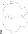
- the manufacture of such a gas bag is carried out, for example, using a in the FIG. 2 exemplified axisymmetric designs of a gas bag blank 10, which is also referred to as a "butterfly" design.
- the Indian FIG. 2 illustrated airbag blank 10 has two with respect to a central axis 11 symmetrical halves 12, 13.
- the gas bag is folded once along the central axis 11, whereby due to the symmetrical design, the two halves 12, 13 of the airbag blank 10 including their edges come to rest on each other and a common outer edge and thus outer contour 5 (see. FIG. 1 ) form.
- the two superposed fabric layers 12, 13 of the airbag blank 10 are connected together along its edge.
- the airbag blank 10 of FIG. 2 also has an opening 14 for introducing a gas generator or a gas generator area into the gas bag 1.
- the attachment of the gas generator to the gas bag 1 can, for example, according to the figures 7A to 7E of WO 2008/129031 A2 respectively.
- the opening 14 is in the schematic representation of FIG. 1 not shown because it is not essential to the present invention.
- the circumferential seam 2 is formed interrupted in a region 3, i.
- the circumferential seam 2 is to form the outflow opening 3 while locally adjacent to the outflow opening 3 guided such that they are substantially perpendicular to a course substantially parallel to the outer edge 5 of the airbag 1 to a course substantially perpendicular to the Outside edge of the airbag 1 merges and ends at the outer edge 5 of the airbag substantially at right angles.
- Due to the parallel course of the regions 21, 22 of the circumferential seam 2, the outflow opening 3 in the inflated state forms a tubular or cylindrical region whose length depends on the length of the parallel seam regions 21, 22. In this way, gas can flow out of the discharge opening 3 effectively and without much turbulence at the points of interruption of the peripheral seam 2.
- the substantially parallel sections 21, 22 have, for example, a length which lies in the range between 2 mm and 50 mm, in particular in the range between 5 mm and 35 mm.
- the manner of the formation of the outflow opening 3 in the FIG. 1 merely by way of example.
- the circumferential seam 2 adjacent to the outflow opening 3 is merely interrupted, without departing from a course substantially parallel to the outer contour 5 of the airbag 1.
- the circumferential seam 2 is locally reinforced in each case at the point at which it ends to form the outflow opening 3, in order to reliably prevent it from tearing when gas flows out of the outflow opening 3.
- the outer contour 5 of the flat-spread airbag 1 forms a rectilinear region 51 in the region of the outflow opening 3. This further contributes to a substantially cylindrical shape of the exhaust opening 3 in the inflated airbag.
- the outflow opening 3 is closed by an additional seam 4.
- the additional seam 4 connects at least partially the two fabric layers of the gas bag 1 in the region of the outflow opening 3 with each other. This causes a temporary closure of the gas outlet opening 3. This prevents premature gas loss when filling the gas bag 1 with gas of a gas generator in the event of triggering. A pressure build-up in the gas bag can be done faster in this way.
- the additional seam 4 is designed such that it ruptures during the inflation process, in particular when a certain internal pressure and / or a certain internal temperature in the gas bag are reached.
- the tear strength of the additional seam or the time at which the additional seam breaks during the inflation process can be adjusted by certain tuning parameters.
- Such a setting can z. B. via the seam shape.
- Different seam shapes are determined by the FIGS. 4A to 4T will be explained below.
- the stitch width and the thread thickness as well as the thread material can be adjusted for each seam shape.
- the opening of the seam area via the flow through the seam and the melting of the thread can also be used as an opening parameter: the additional seam is designed such that it does not completely seal the outflow opening, so that the hot inner gas of the gas bag is pressed by the additional seam.
- the additional seam consists of a fusible thread. Since the gas temperature is higher than the melting temperature of the thread of the additional seam, this leads to a melting of the thread and thus to an opening of the additional seam. On the melting temperature and the thickness of the thread and the degree of flow through the seam, the time at which the additional seam opens during the inflation, can be adjusted.
- the achievable retention work of the inflated airbag at the throttle formed by the discharge port is proportional to the amount of available gas.
- the additional seam is formed such that it ruptures and gas is discharged from the unfolding gas bag before the occupant receives contact with the gas bag. This ensures that the retired occupant does not bounce on a too hard gas bag. It will reduce the possible maximum retention work.
- FIG. 3 shows a gas bag design in which the gas bag is made of two separate airbag blanks and not from a single airbag blank as in the "butterfly" design of FIG. 1 , Accordingly, the circumferential seam 2 extends along the entire outer circumference of the gas bag 1. Not shown is an opening for introducing a gas generator in the gas bag. As regards the design of the outflow opening 3 and the additional seam 4, there are no differences from the embodiment of FIG. 1 , so that reference is made to the relevant remarks.
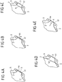
- FIGS. 4A to 4T show different examples with regard to the course and the shape of the additional seam 4.
- FIG. 4A It extends substantially parallel to the outer contour 51 of the gas bag in the region of the outflow opening 3.
- the ends of the additional seam 4a are angled in the direction of the gas bag interior.
- the additional seam 4b extends in a straight line over its entire length and parallel to the outer contour 51 of the gas bag in the area of the outflow opening 3.
- the outflow opening 3 is formed by the additional seam 4b as well as in the FIG. 4A completely closed.
- FIG. 4C closes the additional seam 4c the outflow opening 3 again completely.
- the additional seam 4c is more widely spaced from the outer edge 51 of the gas bag.
- the ends of the additional seam 4c are bent away from the gas bag interior.
- the Figure 4D shows an additional seam 4d, similar to the FIG. 4B is completely rectilinear, but is arranged at a greater distance from the outer contour 51 of the gas bag.
- the additional seam 4a, 4b, 4c, 4d respectively cuts the peripheral seam 2. This ensures a gas-tight closure of the outflow opening 3, as long as the additional seam exists.
- the Figure 4E shows an example in which an additional seam 4e runs perpendicular to the outer edge 51 of the gas bag in the region of the outflow opening 3. Accordingly, the outflow opening 3 is not completely closed, but only reduced in size.
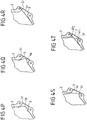
- FIG. 4F Both Figures 4F, 4G and 4H are additional seams 4f, 4g, 4h provided, similar to the FIG. 4B are arranged rectilinearly adjacent to the outer edge 51 of the gas bag and extending parallel to this.
- the closure of the outflow opening 3 is not complete, but only partially. Accordingly, the additional seam cuts the circumferential seam 2 only in an upper point ( FIG. 4F ), in a lower point ( FIG. 4G ) or not at all ( FIG. 4H ).
- FIG. 4I is the rectilinear additional seam 4i more spaced from the outer edge 51 of the airbag. Again, there is a distance between the ends of the additional seam 4i and the circumferential seam 2, so that the outflow opening 3 is only partially closed.
- the circumferential seam 4j, 4k, 4l, 4m is formed respectively of a straight portion and a bent portion, the straight portion intersecting the circumferential seam 2 at one point and the bent portion ends in the region of the outflow opening 3.
- the outflow opening 3 is thus again only partially closed.
- FIGS. 4N, 4O . 4P and 4Q are circumferential seams 4n, 4o, 4p and 4q, which are U-shaped or V-shaped, wherein the central region of the "V" or "U” facing the gas bag interior ( FIGS. 4M, 4O ) or averted ( Figures 4P, 4Q ).
- the type of orientation in turn represents an opening parameter.
- FIGS. 4A to 4T illustrated additional seams can also be realized in any combination, as based on the Figure 4T exemplified.
- the invention is not limited in its execution to the described embodiments, which are to be understood only as an example.
- the type of interruption of the peripheral seam to form an outflow opening can be done in other ways.
- the present invention is not limited to certain types of gas bags.
- the solution according to the invention can be used for example in 1-chamber thorax side airbags, 1-chamber thorax thorax side airbags, 1-chamber head thorax side airbags, 2-chamber thorax thorax side airbags, 2-chamber thoracic thorax side airbags, multi-chamber head thorax basin side airbags, curtain airbags, driver airbags, Passenger airbags, knee airbags and are generally used in airbags that protect in a side impact facing away from the side of the impact occupants (so-called "far-side" airbags).
Landscapes
- Engineering & Computer Science (AREA)
- Mechanical Engineering (AREA)
- Air Bags (AREA)
Description
- Die Erfindung betrifft ein Fahrzeuginsassen-Rückhaltesystem mit einem aufblasbaren Gassack nach den Oberbegriff des Anspruchs 1.
- Es ist allgemein bekannt, einen Gassack eines Fahrzeuginsassen-Rückhaltesystems mit einer oder mehreren Ausströmöffnungen zu versehen, über die Gas zur Vermeidung eines zu großen Innendruckes aus dem Gassack abströmen kann. Gassäcke mit Ausströmöffnungen sind beispielsweise aus der
WO 2007/009427 A1 bekannt. - Die
US 5,536,038 A beschreibt einen Gassack, bei dem mittels eines relativ aufwändigen Gassackdesigns kreisförmige Ausströmöffnungen im Nahtbereich eines aus zwei Gewebelagen gebildeten Gassacks ausgebildet sind. Jede der Gewebelagen weist dabei halbkreisförmig ausgeschnittene Bereiche auf, die die kreisförmigen Ausströmöffnungen bilden. Im Bereich der Ausströmöffnungen ist die die Gewebelagen verbindende Naht unterbrochen. Eine durch eine unterbrochene Naht gebildete Ausströmöffnung ist des weiteren aus derJP 09011845 A - Die
DE 199 34 232 A1 beschreibt einen Gassack, bei dem eine Ausströmöffnung durch eine Unterbrechung einer Umfangsnaht bereitgestellt wird. Es ist des Weiteren im Bereich der Ausströmöffnung eine Reißnaht vorgesehen, die mit einem schwächeren Faden als der Faden der Umfangsnaht ausgeführt ist. DieJP 2004 106711 A - Diese Aufgabe wird erfindungsgemäß durch ein Fahrzeuginsassen-Rückhaltesystem mit den Merkmalen des Anspruchs 1 gelöst. Ausgestaltungen der Erfindung sind in den Unteransprüchen angegeben.
- Danach zeichnet sich die erfindungsgemäße Lösung durch einen Gassack mit mindestens einer Ausströmöffnung aus, die durch Unterbrechung einer Umfangsnaht gebildet ist, die eine erste Gewebelage und eine zweite Gewebelage des Gassacks entlang ihres Randes miteinander verbindet. Im unterbrochenen Bereich, der die Ausströmöffnung bildet, ist eine Zusatznaht vorgesehen, die die Ausströmöffnung vollständig verschließt. Die Zusatznaht ist dabei derart ausgestaltet, dass sie während des Aufblasvorgangs öffnet und damit die Ausströmöffnung vollständig freigibt. Insbesondere öffnet die Zusatznaht bei Vorliegen einer während eines Aufblasvorgangs eintretenden Bedingung, bei der es sich beispielsweise um das Erreichen eines bestimmten Innendrucks des Gassacks oder das Erreichen einer bestimmten Temperatur innerhalb des Gassacks handelt. Der Innendruck führt dabei zu einer Bewegung der Gassack-Gewebelagen zueinander.
- Weiter ist vorgesehen, dass die Umfangsnaht zur Bildung einer Ausströmöffnung derart unterbrochen ist, dass sie auf beiden Seiten der Ausströmöffnung einen sich im wesentlichen senkrecht zum angrenzenden Rand des Gassacks erstreckenden Abschnitt ausbildet und jeweils am Rand des Gassacks endet. Hierdurch bildet die Ausströmöffnung im aufgeblasenen Zustand einen rohrförmigen oder zylindrischen Bereich aus. Die auf beiden Seiten der Ausströmöffnung entsprechend verlaufenden Umfangsnähte bilden dabei eine Art Kanal. Das Gas kann dadurch effektiv und ohne größere Verwirbelung an den Unterbrechungsstellen der Umfangsnaht aus der Ausströmöffnung ausströmen. Der Querschnitt des rohrförmigen oder zylindrischen Bereichs der Ausströmöffnung ist beispielsweise kreisförmig oder oval.
- Die erfindungsgemäße Lösung ermöglicht es dabei, das Abströmen von Gas aus dem Gassack zu verzögern, bis sich beispielsweise ein bestimmter Innendruck im Gassack aufgebaut hat. Dieser initiale Druckaufbau kann erfindungsgemäß schneller erfolgen, als wenn die Ausströmöffnung von vornherein offen wäre, da durch den zeitweiligen Verschluss der Ausströmöffnung ein vorzeitiger Gasverlust verhindert wird. Gleichzeitig wird eine Lösung bereitgestellt, bei der das Risiko des Abdrückens der Ausströmöffnung durch den Fahrzeuginsassen oder intrudierende Fahrzeugkomponenten aufgrund der Ausbildung der Ausströmöffnung in der Umfangsnaht des Gassacks minimiert ist. Ein solches Abdrücken führte zu einem unerwünschten zu harten Insassenrückhalt.
- Eine Umfangsnaht im Sinne der vorliegenden Erfindung ist jede Verbindung, auch eine klebende Verbindung, die mindestens eine erste Gewebelage und eine zweite Gewebelage entlang ihres Randes miteinander verbindet und dementsprechend im Wesentlichen parallel am oder in einem Abstand zum Rand bzw. zur Außenkontur des Gassacks verläuft. Die Umfangsnaht kann dabei aus unterschiedlichen Einzelnähten zusammengesetzt sein, die parallel und/oder aufeinanderfolgend verlaufen. Weiter ist es möglich, dass der Gassack mehr als zwei Gewebelagen aufweist. Beispielsweise ist eine vordere und eine hintere Gassackhülle jeweils durch eine doppelte Gewebelage gebildet, so dass insgesamt vier Gewebelagen vorliegen. Die Gewebelagen des Gassacks können aus einem beliebigen Gassackmaterial bestehen.
- Die erfindungsgemäß vorgesehene Zusatznaht verschließt die Ausströmöffnung, d. h., dass die Ausströmöffnung vollständig verschlossen ist. Bei einem lediglich teilweisen Verschluss wird ein Gasaustritt bis zum Öffnen der Zusatznaht nicht verhindert, sondern lediglich reduziert. Auch dies führt zu einem beschleunigten Druckanstieg im Gassackinneren und damit zu einem früheren Aufbau einer Rückhaltekraft am Fahrzeuginsassen.
- Unter einem "Öffnen" der Zusatznaht wird jede Art der Auflösung oder Beseitigung der Zusatznaht verstanden. Ein "Öffnen" der Zusatznaht umfasst dabei beispielsweise ein Reißen der Zusatznaht oder ein Schmelzen einer aus einem Kunststoff hergestellten Zusatznaht bei Vorliegen einer bestimmten Temperatur im Gassackinneren. Zur Herstellung der Zusatznaht können grundsätzlich sämtliche bekannte Nahtmaterialien und Nahtformen verwendet werden.
- In einer Ausgestaltung der Erfindung ist die Zusatznaht derart ausgestaltet, dass sie öffnet, bevor ein in Normalposition sitzender rückzuhaltender Fahrzeuginsasse in Rückhaltekontakt mit dem Gassack tritt. Das Öffnen der Zusatznaht erfolgt also relativ kurze Zeit nach Beginn des Entfaltungsvorgangs und vor Erreichen des Maximums der Belastung. Hierdurch wird sichergestellt, dass die durch die Ausströmöffnung bereitgestellten Vorteile, nämlich das Verhindern eines zu großen Innendrucks und damit eines zu harten Insassenrückhalts, bereits eingetreten sind, wenn der rückzuhaltende Fahrzeuginsasse in Kontakt mit dem Gassack tritt.
- In einer weiteren Ausgestaltung ist die Ausströmöffnung derart in der Umfangsnaht des Gassacks angeordnet, dass sie nicht in Kontakt mit einem rückzuhaltenden Fahrzeuginsassen oder mit intrudierenden Fahrzeugkomponenten treten kann. Hierzu ist die Ausströmöffnung bei einem als Seitengassack ausgebildeten Gassack beispielsweise an einem in Bezug auf die Fahrzeugrichtung vorderen Bereich des Gassacks ausgebildet. Auf diese Weise wird vermieden, dass die Ausströmöffnung durch den Fahrzeuginsassen abgedrückt und dadurch das Entweichen von Gas aus der Ausströmöffnung verhindert wird.
- Die im Bereich einer Auslassöffnung realisierte Zusatznaht kann auf verschiedene Weise variiert werden, um das Öffnungsverhalten des Gassacks den Erfordernissen des Rückhalts anzupassen. Hierzu können zum einen unterschiedliche Formen der Zusatznaht vorgesehen sein. Beispielsweise kann mindestens eine Zusatznaht im wesentlichen parallel oder senkrecht zur Außenkontur des Gassacks im Bereich der Ausströmöffnung verlaufen. Des Weiteren kann die Zusatznaht die Ausströmöffnung vollständig oder lediglich teilweise verschließen. Sie kann gerade oder gebogen verlaufen und/oder an ihrem Rand abgerundet ausgebildet sein. Zum anderen können die Stichweite des Nahtbereiches und/oder die Parameter des die Reißnaht bildenden Fadens als weitere Abstimmungsparameter variiert bzw. eingestellt werden.
- In einer weiteren Ausführungsvariante ist vorgesehen, dass die Zusatznaht die Umfangsnaht zumindest einmal schneidet. Hierdurch wird sichergestellt, dass zwischen der Zusatznaht und der Umfangsnaht kein Gas durchströmen und entweichen kann, noch während die Zusatznaht existiert. Erfindungsgemäß verläuft die Außenkontur des Gassacks im Bereich der Ausströmöffnung im Wesentlichen stetig geradlinig. Die Außenkante des Gassacks folgt somit auch im Bereich der Ausströmöffnung der Außenkontur, ohne dass der Gassack im Bereich der Ausströmöffnungen Aussparungen oder Einbuchtungen aufweist, wie es bei der
US 5,536,038 A vorgesehen ist. Die einzelnen Gewebelagen des Gassacks sind somit zur Bildung einer Ausströmöffnung nicht mit Einbuchtungen oder Ausschneidungen versehen. Vielmehr liegen die Gewebelagen im Bereich der Ausströmöffnung im ausgebreiteten Zustand parallel aneinander, unter Ausbildung eines gemeinsamen Randbereichs, der der Außenkontur des Gassacks folgt und beispielsweis geradlinig ausgebildet ist. - Bei Aufblasen und Entfalten des Gassacks und nach Öffnen der Zusatznaht bildet die Ausströmöffnung eine kreisförmige oder zylindrische Form, in Abhängigkeit von der Ausgestaltung der Umfangsnaht angrenzend an die Ausströmöffnung.
- Die erste und zweite Gewebelage, die durch die Umfangsnaht zur Ausbildung des Gassacks in ihrem Randbereich miteinander verbunden sind, können aus einem einzigen oder aus unterschiedlichen Gewebezuschnitten gebildet sein. So ist in einer Ausgestaltung der Erfindung vorgesehen, dass die beiden Gewebelagen durch zwei aufeinander geklappte Bereiche eines einzigen, symmetrischen Gewebezuschnitts gebildet sind. Ein solcher, symmetrischer Gewebezuschnitt wird auch als "Butterfly-Design" bezeichnet. Aufgrund des symmetrischen Zuschnitts können die Gassäcke rechts-links-gleich bis zur Faltung produziert werden, d. h. die Gassäcke können sowohl auf der rechten Seite als auch auf der linken Fahrzeugseite eingesetzt werden, was den Herstellungsprozess vereinfacht.
- In einer alternativen Ausgestaltung sind die beiden Gewebelagen durch zwei gesonderte Gewebezuschnitte gebildet, die aufeinander gelegt und mittels der Umfangsnaht verbunden sind. Da bei dieser Ausgestaltung kein durch eine Falte gebildeter Randbereich vorliegt, sind die beiden Gewebelagen entlang ihres gesamten Umfanges miteinander verbunden (abgesehen von einer Öffnung für einen Gasgenerator oder einen Einfüllstutzen sowie abgesehen von den erfindungsgemäßen Ausströmöffnungen).
- Eine weitere Ausgestaltung sieht vor, dass die Festigkeit der Zusatznaht in dem Sinne an eine OOP-Situation (OOP = "Out-Of-Position") angepasst ist, dass die Zusatznaht öffnet, bevor der Innendruck im Gassack OOP-kritisch wird. Die Zusatznaht ist also derart ausgestaltet, dass sie öffnet, bevor der Gassackdruck einen Wert erreicht, der für einen sich in einer OOP-Situation befindenden Fahrzeuginsassen ungünstig wäre.
- Der Gassack kann mehrere Kammern aufweisen, wobei eine erfindungsgemäße, mit einer Zusatznaht versehene Ausströmöffnung in mindestens einer der Kammern realisiert ist.
- Die Erfindung wird nachfolgend unter Bezugnahme auf die Figuren der Zeichnung anhand mehrerer Ausführungsbeispiele näher erläutert. Es zeigen:
- Fig. 1
- ein erstes Ausführungsbeispiel eines Seitengassacks mit einer im Bereich einer Ausströmöffnung des Gassacks vorgesehenen Zusatznaht;
- Fig. 2
- einen Gassackzuschnitt zur Herstellung eines Gassacks gemäß der
Figur 1 ; - Fig. 3
- ein zweites Ausführungsbeispiel eines Seitengassacks mit einer im Bereich einer Ausströmöffnung des Gassacks vorgesehenen Zusatznaht; und
- Figuren 4A - 4T
- mögliche Nahtverläufe einer Zusatznaht im Bereich einer Ausströmöffnung eines Gassacks.
- Die Figuren betreffen einen Gassack eines Fahrzeuginsassen-Rückhaltesystems. Das Fahrzeuginsassen-Rückhaltesystem weist neben dem dargestellten Gassack weitere typische Elemente eines Fahrzeuginsassen-Rückhaltesystems auf, wie insbesondere einen Gasgenerator, Airbagsensoren und eine Steuervorrichtung. Des Weiteren kann das Rückhaltesystem in Abhängigkeit von der konkreten Implementierung Elemente wie einen Diffusor, eine Gaslanze und/oder ein Gehäuse oder eine andere Umhüllung aufweisen. Solche Elemente sind in den Figuren nicht gesondert dargestellt, da sie dem Fachmann bekannt sind.
- Es wird weiter darauf hingewiesen, dass die im folgenden beschriebenen Gassäcke zwar als Seitenairbags ausgebildet sind. Entsprechende Ausströmöffnungen können jedoch ebenso in Gassäcken beliebiger anderen Airbags implementiert sein.
- Die
Figur 1 zeigt einen flach ausgebreiteten Gassack 1 eines Fahrzeuginsassen-Rückhaltesystems, der zwei Gewebelagen aufweist, die mittels einer Umfangsnaht 2 miteinander verbunden sind. Die Herstellung eines solchen Gassacks erfolgt beispielsweise unter Verwendung eines in derFigur 2 beispielhaft dargestellten achsensymmetrischen Designs eines Gassackzuschnitts 10, das auch als "Butterfly"-Design bezeichnet wird. Der in derFigur 2 dargestellte Gassackzuschnitt 10 weist zwei bezüglich einer Mittelachse 11 symmetrische Hälften 12, 13 auf. Der Gassack wird entlang der Mittelachse 11 einmal gefaltet, wobei aufgrund des symmetrischen Designs die beiden Hälften 12, 13 des Gassackzuschnitts 10 einschließlich ihrer Ränder aufeinander zu liegen kommen und eine gemeinsame Außenkante und damit Außenkontur 5 (vgl.Figur 1 ) bilden. Über die Umfangsnaht 2 werden die beiden aufeinandergelegten Gewebelagen 12, 13 des Gassackzuschnitts 10 entlang ihres Randes miteinander verbunden. - Der Gassackzuschnitt 10 der
Figur 2 weist des Weiteren eine Öffnung 14 zur Einbringung eines Gasgenerators oder eines Gasgeneratorbereichs in den Gassack 1 auf. Die Befestigung des Gasgenerators am Gassack 1 kann dabei beispielsweise entsprechend den Figuren 7A bis 7E derWO 2008/129031 A2 erfolgen. Die Öffnung 14 ist in der schematischen Darstellung derFigur 1 nicht dargestellt, da sie für die vorliegende Erfindung nicht wesentlich ist. - Zur Ausbildung einer Ausströmöffnung ist die Umfangsnaht 2 in einem Bereich 3 unterbrochen ausgebildet, d.h. die Unterbrechung der Umfangsnaht 2 bildet die Ausströmöffnung 3. Die Umfangsnaht 2 ist zur Ausbildung der Ausströmöffnung 3 dabei lokal angrenzend an die Ausströmöffnung 3 derart geführt, dass sie von einem Verlauf im wesentlichen parallel zur Außenkante 5 des Gassacks 1 zu einem Verlauf im Wesentlichen senkrecht zur Außenkante des Gassacks 1 übergeht und an der Außenkante 5 des Gassacks im Wesentlichen im rechten Winkel endet. Dabei entstehen zwei im Wesentlichen parallele Abschnitte 21, 22 der Umfangsnaht 2, die die Ausströmöffnung 3 begrenzen und an der Außenkante 5 enden. Aufgrund des parallelen Verlaufs der Bereiche 21, 22 der Umfangsnaht 2 bildet die Ausströmöffnung 3 im aufgeblasenen Zustand einen rohrförmigen oder zylindrischen Bereich aus, dessen Länge von der Länge der parallelen Nahtbereiche 21, 22 abhängt. Auf diese Weise kann Gas effektiv und ohne größere Verwirbelung an den Unterbrechungsstellen der Umfangsnaht 2 aus der Ausströmöffnung 3 ausströmen.
- Die im Wesentlichen parallelen Abschnitte 21, 22 weisen beispielsweise eine Länge auf, die im Bereich zwischen 2 mm und 50 mm, insbesondere im Bereich zwischen 5 mm und 35 mm liegt.
- Es wird dabei darauf hingewiesen, dass die Art und Weise der Ausbildung der Ausströmöffnung 3 in der
Figur 1 lediglich beispielhaft zu verstehen ist. Ebenso ist es beispielsweise denkbar, dass die Umfangsnaht 2 angrenzend an die Ausströmöffnung 3 lediglich unterbrochen ist, ohne von einem Verlauf im Wesentlichen parallel zu der Außenkontur 5 des Gassacks 1 abzuweichen. Dabei kann ggf. vorgesehen sein, dass die Umfangsnaht 2 jeweils an der Stelle, an der sie zur Bildung der Ausströmöffnung 3 endet, lokal verstärkt ist, um ein Ausreißen bei Ausströmen von Gas aus der Ausströmöffnung 3 sicher zu verhindern. - Die Außenkontur 5 des flach ausgebreiteten Gassacks 1 bildet im Bereich der Ausströmöffnung 3 einen geradlinigen Bereich 51 aus. Dies trägt weiter zu einer im wesentlichen zylindrischen Form der Ausblasöffnung 3 im aufgeblasenen Gassack bei.
- Es ist vorgesehen, dass die Ausströmöffnung 3 durch eine Zusatznaht 4 verschlossen ist. Die Zusatznaht 4 verbindet dabei zumindest teilweise die beiden Gewebelagen des Gassacks 1 im Bereich der Ausströmöffnung 3 miteinander. Dies bewirkt einen zeitweiligen Verschluss der Gasausströmöffnung 3. Hierdurch wird ein vorzeitiger Gasverlust bei Befüllen des Gassacks 1 mit Gas eines Gasgenerators im Auslösefall vermieden. Ein Druckaufbau im Gassack kann auf diese Weise schneller erfolgen. Gleichzeitig ist die Zusatznaht 4 derart ausgebildet, dass sie während des Aufblasvorgangs reißt, insbesondere wenn ein bestimmter Innendruck und/oder eine bestimmte Innentemperatur im Gassack erreicht sind.
- Die Reißfestigkeit der Zusatznaht bzw. der Zeitpunkt, zu dem die Zusatznaht während des Aufblasvorgangs reißt, kann durch bestimmte Abstimmungsparameter eingestellt werden. Eine solche Einstellung kann z. B. über die Nahtform erfolgen. Unterschiedliche Nahtformen werden anhand der
Figuren 4A bis 4T weiter unten erläutert werden. Als weitere Abstimmungsparameter können für jede Nahtform zusätzlich die Stichbreite und die Fadendicke sowie das Fadenmaterial eingestellt werden. - Das Öffnen des Nahtbereichs über die Durchströmung der Naht und das Aufschmelzen des Fadens ist ebenfalls als Öffnungsparameter einsetzbar: die Zusatznaht ist dabei derart ausgebildet, dass sie die Ausströmöffnung nicht vollständig abdichtet, so dass durch die Zusatznaht das heiße Innengas des Gassacks gedrückt wird. Gleichzeitig besteht die Zusatznaht aus einem schmelzbaren Faden. Da die Gastemperatur höher als die Schmelztemperatur des Fadens der Zusatznaht ist, führt dies zu einem Schmelzen des Fadens und damit zu einer Öffnung der Zusatznaht. Über die Schmelztemperatur und die Dicke des Fadens sowie den Grad der Durchströmung der Naht kann der Zeitpunkt, zu dem die Zusatznaht während des Aufblasvorgangs öffnet, eingestellt werden.
- Die erzielbare Rückhaltearbeit des aufgeblasenen Gassacks an der durch die Ausströmöffnung gebildeten Drossel ist proportional zur Menge des zur Verfügung stehenden Gases.
- Bevorzugt ist die Zusatznaht derart ausgebildet, dass sie reißt und ein Abströmen von Gas aus dem sich entfaltenden Gassack erfolgt, bevor der Insasse Kontakt zum Gassack aufnimmt. Hierdurch wird sichergestellt, dass der rückzuhaltende Insasse nicht auf einen zu harten Gassack aufprallt. Es wird die mögliche maximale Rückhaltearbeit reduziert.
- Die
Figur 3 zeigt ein Gassackdesign, bei dem der Gassack aus zwei gesonderten Gassackzuschnitten hergestellt ist und nicht aus einem einzigen Gassackzuschnitt wie beim "Butterfly"-Design derFigur 1 . Dementsprechend erstreckt sich die Umfangsnaht 2 entlang des gesamten Außenumfanges des Gassacks 1. Nicht dargestellt ist eine Öffnung zum Einführen eines Gasgenerators in den Gassack. Was die Ausgestaltung der Ausströmöffnung 3 und der Zusatznaht 4 angeht, ergeben sich keine Unterschiede zu der Ausgestaltung derFigur 1 , so dass auf die diesbezüglichen Ausführungen verwiesen wird. - Die
Figuren 4A bis 4T zeigen unterschiedliche Beispiele hinsichtlich des Verlaufs und der Form der Zusatznaht 4. - In der
Figur 4A erstreckt sich die Zusatznaht 4a über die gesamte Breite der Ausströmöffnung 3. Sie verläuft dabei im Wesentlichen parallel zu der Außenkontur 51 des Gassacks im Bereich der Ausströmöffnung 3. Die Enden der Zusatznaht 4a sind in Richtung des Gassackinneren abgewinkelt. In derFigur 4B verläuft die Zusatznaht 4b über ihre gesamte Länge geradlinig und parallel zur Außenkontur 51 des Gassacks im Bereich der Ausströmöffnung 3. Die Ausströmöffnung 3 wird durch die Zusatznaht 4b ebenso wie bei derFigur 4A vollständig verschlossen. - Bei der
Figur 4C verschließt die Zusatznaht 4c die Ausströmöffnung 3 wiederum vollständig. Die Zusatznaht 4c ist jedoch stärker von der Außenkante 51 des Gassacks beabstandet. Die Enden der Zusatznaht 4c sind dabei vom Gassackinneren weg gebogen. DieFigur 4D zeigt eine Zusatznaht 4d, die ähnlich wie bei derFigur 4B vollständig geradlinig verläuft, jedoch in größerem Abstand von der Außenkontur 51 des Gassacks angeordnet ist. - Bei den Ausgestaltungen der
Figuren 4A bis 4D schneidet die Zusatznaht 4a, 4b, 4c, 4d jeweils die Umfangsnaht 2. Hierdurch wird ein gasdichter Verschluss der Ausströmöffnung 3 sichergestellt, so lange die Zusatznaht existiert. - Die
Figur 4E zeigt ein Beispiel bei dem eine Zusatznaht 4e senkrecht zur Außenkante 51 des Gassacks im Bereich der Ausströmöffnung 3 verläuft. Dementsprechend wird die Ausströmöffnung 3 nicht vollständig verschlossen, sondern in ihrer Größe lediglich verkleinert. - Bei den
Figuren 4F, 4G und 4H sind Zusatznähte 4f, 4g, 4h vorgesehen, die ähnlich wie bei derFigur 4B geradlinig angrenzend an die Außenkante 51 des Gassacks und parallel zu dieser verlaufend angeordnet sind. Der Verschluss der Ausströmöffnung 3 erfolgt jedoch nicht vollständig, sondern nur teilweise. Dementsprechend schneidet die Zusatznaht die Umfangsnaht 2 lediglich in einem oberen Punkt (Figur 4F ), in einem unteren Punkt (Figur 4G ) oder überhaupt nicht (Figur 4H ). - Bei der
Figur 4I ist die geradlinig verlaufende Zusatznaht 4i stärker von der Außenkante 51 des Gassacks beabstandet. Auch hier befindet sich zwischen den Enden der Zusatznaht 4i und der Umfangsnaht 2 ein Abstand, so dass die Ausströmöffnung 3 nur teilweise verschlossen ist. - Bei den
Figuren 4J ,4K, 4L und 4M ist die Umfangsnaht 4j, 4k, 4l, 4m jeweils aus einem geraden Abschnitt und einem gebogenen Abschnitt gebildet, wobei der geradlinige Abschnitt die Umfangsnaht 2 in einem Punkt schneidet und der gebogene Abschnitt im Bereich der Ausströmöffnung 3 endet. Die Ausströmöffnung 3 ist somit wiederum nur teilweise verschlossen. Über die Orientierung des gebogenen Abschnitts kann der Widerstand eingestellt werden, den die Zusatznaht dem ausströmenden Gas entgegenstellt, und damit auch der Zeitpunkt beeinflusst werden, zu dem die Zusatznaht reißt. - In den
Figuren 4N, 4O ,4P und 4Q befinden sich Umfangsnähte 4n, 4o, 4p und 4q, die U-förmig oder V-förmig ausgebildet sind, wobei der mittlere Bereich des "V" oder "U" dem Gassackinneren zugewandt (Figuren 4M, 4O ) oder abgewandt (Figuren 4P, 4Q ) ist. Die Art der Orientierung stellt wiederum einen Öffnungsparameter dar. - Bei den
Figuren 4R und 4S sind wieder geradlinig ausgebildete Zusatznähte 4r, 4s vorgesehen, die die Ausströmöffnung 3 vollständig verschließen, die sich jedoch bei dieser Ausgestaltung nicht parallel zur Außenkante 51 des Gassacks erstrecken, sondern winklig dazu. - In der
Figur 4T sind zwei gekreuzte, jeweils geradlinig verlaufende Zusatznähte 4t1, 4t2 vorgesehen, die entsprechend den Nähten 4r, 4s derFiguren 4R, 4S verlaufen. - Die in den
Figuren 4A bis 4T dargestellten Zusatznähte können auch in beliebiger Kombination realisiert werden, wie anhand derFigur 4T beispielhaft dargestellt. - Die Erfindung beschränkt sich in ihrer Ausführung nicht auf die beschriebenen Ausführungsbeispiele, die lediglich beispielhaft zu verstehen sind. Beispielsweise kann die Art der Unterbrechung der Umfangsnaht zur Ausbildung einer Ausströmöffnung in anderer Weise erfolgen. Auch ist die vorliegende Erfindung nicht beschränkt auf bestimmte Arten von Gassäcken. Die erfindungsgemäße Lösung kann beispielsweise bei 1-Kammer Thorax Seitenairbags, 1-Kammer Becken Thorax Seitenairbags, 1-Kammer Kopf Thorax Seitenairbags, 2-Kammer Becken Thorax Seitenairbags, 2-Kammer Kopf Thorax Seitenairbags, Mehrkammer Kopf Thorax Becken Seitenairbags, Kopfairbags, Fahrerairbags, Beifahrerairbags, Knieairbags sowie allgemein bei Airbags eingesetzt werden, die bei einem Seitenaufprall den der Seite des Aufpralls abgewandt sitzenden Insassen schützen (sogenannte "Far-Side" Airbags).
Claims (11)
- Fahrzeuginsassen-Rückhaltesystem mit- einem mit Gas aufblasbaren Gassack (1), der mindestens eine erste Gewebelage und eine zweite Gewebelage aufweist, die entlang ihres Randes (5) mittels einer Umfangsnaht (2) miteinander verbunden sind, und- mit mindestens einer Ausströmöffnung (3), über die Gas aus dem Gassack (1) ausströmen kann, wobei- die Ausströmöffnung (3) durch eine Unterbrechung der Umfangsnaht (2) gebildet ist, und- die Umfangsnaht (2) zur Bildung einer Ausströmöffnung (3) derart unterbrochen ist, dass sie auf beiden Seiten der Ausströmöffnung (3) einen sich im wesentlichen senkrecht zum angrenzenden Rand (51) des Gassacks (1) erstreckenden Abschnitt (21, 22) ausbildet und jeweils am Rand (51) des Gassacks (1) endet,gekennzeichnet durch
mindestens eine im Bereich der Ausströmöffnung (3) ausgebildete Zusatznaht (4b), die die Ausströmöffnung (3) vollständig verschließt, wobei die Zusatznaht (4b) derart ausgestaltet ist, dass sie während des Aufblasvorgangs öffnet, und wobei die Zusatznaht (4b) über ihre gesamte Länge gradlinig verläuft und die sich senkrecht erstreckenden Abschnitte der Umfangsnaht (2) schneidet. - Fahrzeuginsassen-Rückhaltesystem nach Anspruch 1, dadurch gekennzeichnet, dass die Zusatznaht (4b) derart ausgestaltet ist, dass sie die Ausströmöffnung (3) bis zum Erreichen einer während eines Aufblasvorgangs eintretenden Bedingung verschließt.
- Fahrzeuginsassen-Rückhaltesystem nach Anspruch 1 oder 2, dadurch gekennzeichnet, dass die Zusatznaht (4b) derart ausgestaltet ist, dass sie öffnet, bevor ein rückzuhaltender Fahrzeuginsasse in Kontakt mit dem Gassack tritt.
- Fahrzeuginsassen-Rückhaltesystem nach einem der vorangehenden Ansprüche, dadurch gekennzeichnet, dass die Ausströmöffnung (3) derart in der Umfangsnaht (2) des Gassacks angeordnet ist, dass sie nicht verschlossen wird durch Kontakt des Gassacks mit einem rückzuhaltenden Fahrzeuginsassen oder mit intrudierenden Fahrzeugkomponenten.
- Fahrzeuginsassen-Rückhaltesystem nach Anspruch 4, dadurch gekennzeichnet, dass die Ausströmöffnung (3) bei einem als Seitengassack ausgebildeten Gassack an einem in Bezug auf die Fahrzeugrichtung vorderen Bereich des Gassack ausgebildet ist.
- Fahrzeuginsassen-Rückhaltesystem nach einem der vorangehenden Ansprüche, dadurch gekennzeichnet, dass im Bereich der Ausströmöffnung (3) mindestens eine Zusatznaht (4b) angeordnet ist, die im wesentlichen parallel zur Außenkontur (51) des Gassacks im Bereich der Ausströmöffnung (3) verläuft.
- Fahrzeuginsassen-Rückhaltesystem nach einem der vorangehenden Ansprüche, dadurch gekennzeichnet, dass die Außenkontur (5, 51) des Gassacks im Bereich der Ausströmöffnung (3) im wesentlichen stetig ist.
- Fahrzeuginsassen-Rückhaltesystem nach einem der vorangehenden Ansprüche, dadurch gekennzeichnet, dass die Außenkontur (5, 51) des Gassacks im Bereich der Ausströmöffnung (3) im wesentlichen geradlinig ist
- Fahrzeuginsassen-Rückhaltesystem nach Anspruch 7 oder 8, dadurch gekennzeichnet, dass die Außenkante (51) des Gassacks im Bereich der Ausströmöffnung (3) keine Aussparungen oder Einbuchtungen aufweist.
- Fahrzeuginsassen-Rückhaltesystem nach einem der vorangehenden Ansprüche, dadurch gekennzeichnet, dass die Ausströmöffnung (3) im aufgeblasenen Zustand des Gassacks einen im wesentlichen zylindrischen Bereich bildet.
- Fahrzeuginsassen-Rückhaltesystem nach einem der vorangehenden Ansprüche, dadurch gekennzeichnet, dass die Festigkeit der Zusatznaht (4b) in dem Sinne an eine OOP-Situation angepasst ist, dass die Zusatznaht (4b) öffnet, bevor der Innendruck im Gassack OOP-kritisch wird.
Applications Claiming Priority (2)
| Application Number | Priority Date | Filing Date | Title |
|---|---|---|---|
| DE102009005696A DE102009005696A1 (de) | 2009-01-19 | 2009-01-19 | Fahrzeuginsassen-Rückhaltesystem mit einem aufblasbaren Gassack |
| PCT/EP2010/050567 WO2010081909A1 (de) | 2009-01-19 | 2010-01-19 | Fahrzeuginsassen-rückhaltesystem mit einem aufblasbaren gassack |
Publications (2)
| Publication Number | Publication Date |
|---|---|
| EP2387518A1 EP2387518A1 (de) | 2011-11-23 |
| EP2387518B1 true EP2387518B1 (de) | 2018-03-14 |
Family
ID=41051627
Family Applications (1)
| Application Number | Title | Priority Date | Filing Date |
|---|---|---|---|
| EP10704117.0A Not-in-force EP2387518B1 (de) | 2009-01-19 | 2010-01-19 | Fahrzeuginsassen-rückhaltesystem mit einem aufblasbaren gassack |
Country Status (5)
| Country | Link |
|---|---|
| US (1) | US8292325B2 (de) |
| EP (1) | EP2387518B1 (de) |
| JP (1) | JP2012515113A (de) |
| DE (1) | DE102009005696A1 (de) |
| WO (1) | WO2010081909A1 (de) |
Families Citing this family (3)
| Publication number | Priority date | Publication date | Assignee | Title |
|---|---|---|---|---|
| JP2014205481A (ja) * | 2013-03-18 | 2014-10-30 | 豊田合成株式会社 | エアバッグ装置 |
| US9834168B2 (en) * | 2015-09-16 | 2017-12-05 | Ford Global Technologies, Llc | Side airbag including forward facing vent |
| DE102017212295A1 (de) * | 2017-07-18 | 2019-01-24 | Volkswagen Aktiengesellschaft | Gassack für ein Fahrzeuginsassen-Rückhaltesystem |
Citations (1)
| Publication number | Priority date | Publication date | Assignee | Title |
|---|---|---|---|---|
| JP2004106711A (ja) * | 2002-09-19 | 2004-04-08 | Nippon Plast Co Ltd | エアバッグ |
Family Cites Families (31)
| Publication number | Priority date | Publication date | Assignee | Title |
|---|---|---|---|---|
| US3451693A (en) | 1967-09-01 | 1969-06-24 | Eaton Yale & Towne | Vehicle safety method and apparatus |
| JPH0644759Y2 (ja) * | 1986-08-26 | 1994-11-16 | タカタ株式会社 | エアバッグの圧力調節装置 |
| US5007662A (en) * | 1989-10-16 | 1991-04-16 | Ford Motor Company | Air bag relief valve |
| US5280953A (en) * | 1992-11-25 | 1994-01-25 | General Motors Corporation | Displacement responsive air bag vent |
| US5478111A (en) | 1993-08-11 | 1995-12-26 | Morton International, Inc. | Dynamic burn vents for the cushion of an air bag module |
| JPH07205738A (ja) | 1994-01-13 | 1995-08-08 | Toyo Tire & Rubber Co Ltd | 車両用エアバッグ |
| US5492363A (en) * | 1994-09-07 | 1996-02-20 | Takata, Inc. | Flow regulating air bag valve |
| US5536038A (en) | 1995-02-01 | 1996-07-16 | Trw Vehicle Safety Systems Inc. | Side impact inflatable restraint with vent openings |
| JP3626529B2 (ja) * | 1995-03-31 | 2005-03-09 | 本田技研工業株式会社 | エアバッグ装置の製造方法 |
| JP3642833B2 (ja) | 1995-06-28 | 2005-04-27 | マツダ株式会社 | エアバッグ装置の袋体構造 |
| US5603526A (en) * | 1996-01-16 | 1997-02-18 | Morton International, Inc. | Pressure vent for air bag cushion |
| JP3397041B2 (ja) | 1996-03-28 | 2003-04-14 | 豊田合成株式会社 | 側突用エアバッグ |
| JPH09323604A (ja) * | 1996-06-07 | 1997-12-16 | Honda Motor Co Ltd | 乗員拘束装置用エアバッグ |
| US5704639A (en) * | 1996-07-09 | 1998-01-06 | Breed Automotive Technology, Inc. | Pressure sensitive airbag vent mechanism |
| DE29612500U1 (de) * | 1996-07-18 | 1996-11-14 | Trw Repa Gmbh | Gassack für ein Fahrzeuginsassen-Rückhaltesystem |
| US6254130B1 (en) * | 1998-04-13 | 2001-07-03 | Georgia Tech Research Corporation | Method and apparatus for controlling air bag deployment |
| DE29813081U1 (de) | 1998-07-22 | 1998-11-19 | Trw Repa Gmbh | Gassack mit Entlastungsöffnung |
| DE19859767B4 (de) | 1998-12-23 | 2005-09-29 | Autoliv Development Ab | Gassack mit Abströmöffnung |
| DE19932696C1 (de) * | 1999-07-15 | 2000-09-07 | Daimler Chrysler Ag | Insassenschutzvorrichtung mit zumindest zwei mit Gas auffüllbaren Airbags |
| CN1267303C (zh) | 2001-01-23 | 2006-08-02 | 本田技研工业株式会社 | 用于侧撞击的气囊装置 |
| DE10111566B4 (de) * | 2001-03-10 | 2005-11-17 | Daimlerchrysler Ag | Sicherheitsvorrichtung für ein Kraftfahrzeug |
| US6802528B2 (en) * | 2002-04-05 | 2004-10-12 | Ford Global Technologies, Llc | Air bag cushion energy diverter |
| DE10320120A1 (de) | 2003-05-06 | 2004-12-09 | Johann Berger | Aufblasbarer gewebter Luftsack oder Luftgürtel |
| GB2402912A (en) * | 2003-06-20 | 2004-12-22 | Autoliv Dev | Side air-bag |
| DE10327951A1 (de) | 2003-06-21 | 2005-01-27 | Autoliv Development Ab | Gassack für eine Airbag-Vorrichtung |
| DE102004058440B4 (de) | 2004-12-03 | 2007-03-08 | Trw Automotive Gmbh | Gassack für ein Fahrzeuginsassen-Rückhaltesystem |
| JP2007022306A (ja) * | 2005-07-15 | 2007-02-01 | Takata Corp | エアバッグ及びエアバッグ装置 |
| DE102005034250A1 (de) | 2005-07-18 | 2007-02-01 | Takata-Petri (Ulm) Gmbh | Gassack für ein Fahrzeuginsassen-Rückhaltesystem |
| DE202006017996U1 (de) | 2006-11-22 | 2007-02-15 | Takata-Petri Ag | Gassack für ein Kraftfahrzeug |
| DE202007006023U1 (de) | 2007-04-19 | 2007-07-26 | Takata-Petri Ag | Gassackanordnung für ein Fahrzeuginsassen-Rückhaltesystem |
| JP5169203B2 (ja) | 2007-12-20 | 2013-03-27 | 豊田合成株式会社 | エアバッグ装置 |
-
2009
- 2009-01-19 DE DE102009005696A patent/DE102009005696A1/de not_active Withdrawn
-
2010
- 2010-01-19 WO PCT/EP2010/050567 patent/WO2010081909A1/de not_active Ceased
- 2010-01-19 JP JP2011545762A patent/JP2012515113A/ja active Pending
- 2010-01-19 EP EP10704117.0A patent/EP2387518B1/de not_active Not-in-force
-
2011
- 2011-07-18 US US13/185,413 patent/US8292325B2/en not_active Expired - Fee Related
Patent Citations (1)
| Publication number | Priority date | Publication date | Assignee | Title |
|---|---|---|---|---|
| JP2004106711A (ja) * | 2002-09-19 | 2004-04-08 | Nippon Plast Co Ltd | エアバッグ |
Also Published As
| Publication number | Publication date |
|---|---|
| WO2010081909A1 (de) | 2010-07-22 |
| US8292325B2 (en) | 2012-10-23 |
| EP2387518A1 (de) | 2011-11-23 |
| DE102009005696A1 (de) | 2009-10-08 |
| CN102282046A (zh) | 2011-12-14 |
| JP2012515113A (ja) | 2012-07-05 |
| US20110266782A1 (en) | 2011-11-03 |
Similar Documents
| Publication | Publication Date | Title |
|---|---|---|
| EP2203330B1 (de) | Airbagmodul | |
| DE19847854C2 (de) | Zweikammerluftsack | |
| EP2424750B1 (de) | Gassackmodul zum schutz des thorax- und kopfbereichs eines fahrzeuginsassen | |
| EP1086861B1 (de) | Gassack-Schutzeinrichtung | |
| EP1778525B1 (de) | Gassack für ein airbagmodul eines kraftfahrzeuges | |
| EP1568544B2 (de) | Seitenaufprall-Rückhaltevorrichtung | |
| EP1907242B1 (de) | Gassack für ein fahrzeuginsassen-rückhaltesystem | |
| EP2718155B1 (de) | Fahrzeuginsassen-rückhaltesystem mit adaptivem kniegassack | |
| EP1720741B1 (de) | Gassack zum einbau in ein kraftfahrzeug | |
| DE102007056137B4 (de) | Gassack mit einem Einfüllstutzen und Gassackanordnung mit einem Gassack und einem Gasgenerator | |
| DE202007006023U1 (de) | Gassackanordnung für ein Fahrzeuginsassen-Rückhaltesystem | |
| EP2582551B1 (de) | Knieairbaganordnung für fahrzeuge | |
| EP1848615B1 (de) | Airbag sowie verfahren zum herstellen eines airbags | |
| EP1074434B1 (de) | Abdeckung für einen Gassack eines Fahrzeuginsassen-Rückhaltesystems | |
| EP2695777B1 (de) | Gassack für ein Fahrzeuginsassen-Rückhaltesystem und Verfahren zum Herstellen eines Fahrzeuginsassen-Rückhaltesystems | |
| EP2387518A1 (de) | Fahrzeuginsassen-rückhaltesystem mit einem aufblasbaren gassack | |
| EP3168089B1 (de) | Beifahrer-frontgassackbaugruppe, beifahrer-frontgassackmodul und fahrzeuginsassen-rückhaltevorrichtung | |
| DE102004023780A1 (de) | Airbageinrichtung | |
| DE102004058438B3 (de) | Gassack für ein Fahrzeuginsassen-Rückhaltesystem | |
| DE102013113434B4 (de) | Gassackmodul mit einer eine Aufspringfalte aufweisenden Venteinrichtung | |
| EP3613640B1 (de) | Seitengassack für ein fahrzeuginsassen-rückhaltesystem, fahrzeuginsassen-rückhaltesystem sowie fahrzeug | |
| EP2870036B1 (de) | Gassack für ein fahrzeuginsassen-rückhaltesystem | |
| WO2023030806A1 (de) | Lenkrad mit einem gassack | |
| DE10162611A1 (de) | Abdeckung für einen Gassack einer Aufprallschutzvorrichtung für Fahrzeuginsassen | |
| DE102019132199A1 (de) | Gassack für ein Fahrzeuginsassen-Rückhaltesystem |
Legal Events
| Date | Code | Title | Description |
|---|---|---|---|
| PUAI | Public reference made under article 153(3) epc to a published international application that has entered the european phase |
Free format text: ORIGINAL CODE: 0009012 |
|
| 17P | Request for examination filed |
Effective date: 20110816 |
|
| AK | Designated contracting states |
Kind code of ref document: A1 Designated state(s): AT BE BG CH CY CZ DE DK EE ES FI FR GB GR HR HU IE IS IT LI LT LU LV MC MK MT NL NO PL PT RO SE SI SK SM TR |
|
| DAX | Request for extension of the european patent (deleted) | ||
| RAP1 | Party data changed (applicant data changed or rights of an application transferred) |
Owner name: TAKATA AG |
|
| 17Q | First examination report despatched |
Effective date: 20150109 |
|
| GRAP | Despatch of communication of intention to grant a patent |
Free format text: ORIGINAL CODE: EPIDOSNIGR1 |
|
| STAA | Information on the status of an ep patent application or granted ep patent |
Free format text: STATUS: GRANT OF PATENT IS INTENDED |
|
| INTG | Intention to grant announced |
Effective date: 20170517 |
|
| GRAS | Grant fee paid |
Free format text: ORIGINAL CODE: EPIDOSNIGR3 |
|
| GRAJ | Information related to disapproval of communication of intention to grant by the applicant or resumption of examination proceedings by the epo deleted |
Free format text: ORIGINAL CODE: EPIDOSDIGR1 |
|
| GRAL | Information related to payment of fee for publishing/printing deleted |
Free format text: ORIGINAL CODE: EPIDOSDIGR3 |
|
| STAA | Information on the status of an ep patent application or granted ep patent |
Free format text: STATUS: EXAMINATION IS IN PROGRESS |
|
| GRAP | Despatch of communication of intention to grant a patent |
Free format text: ORIGINAL CODE: EPIDOSNIGR1 |
|
| STAA | Information on the status of an ep patent application or granted ep patent |
Free format text: STATUS: GRANT OF PATENT IS INTENDED |
|
| INTC | Intention to grant announced (deleted) | ||
| INTG | Intention to grant announced |
Effective date: 20171017 |
|
| GRAA | (expected) grant |
Free format text: ORIGINAL CODE: 0009210 |
|
| STAA | Information on the status of an ep patent application or granted ep patent |
Free format text: STATUS: THE PATENT HAS BEEN GRANTED |
|
| AK | Designated contracting states |
Kind code of ref document: B1 Designated state(s): AT BE BG CH CY CZ DE DK EE ES FI FR GB GR HR HU IE IS IT LI LT LU LV MC MK MT NL NO PL PT RO SE SI SK SM TR |
|
| REG | Reference to a national code |
Ref country code: GB Ref legal event code: FG4D Free format text: NOT ENGLISH |
|
| REG | Reference to a national code |
Ref country code: CH Ref legal event code: EP Ref country code: AT Ref legal event code: REF Ref document number: 978549 Country of ref document: AT Kind code of ref document: T Effective date: 20180315 |
|
| REG | Reference to a national code |
Ref country code: IE Ref legal event code: FG4D Free format text: LANGUAGE OF EP DOCUMENT: GERMAN |
|
| REG | Reference to a national code |
Ref country code: DE Ref legal event code: R096 Ref document number: 502010014750 Country of ref document: DE |
|
| REG | Reference to a national code |
Ref country code: NL Ref legal event code: MP Effective date: 20180314 |
|
| REG | Reference to a national code |
Ref country code: LT Ref legal event code: MG4D |
|
| PG25 | Lapsed in a contracting state [announced via postgrant information from national office to epo] |
Ref country code: ES Free format text: LAPSE BECAUSE OF FAILURE TO SUBMIT A TRANSLATION OF THE DESCRIPTION OR TO PAY THE FEE WITHIN THE PRESCRIBED TIME-LIMIT Effective date: 20180314 Ref country code: LT Free format text: LAPSE BECAUSE OF FAILURE TO SUBMIT A TRANSLATION OF THE DESCRIPTION OR TO PAY THE FEE WITHIN THE PRESCRIBED TIME-LIMIT Effective date: 20180314 Ref country code: CY Free format text: LAPSE BECAUSE OF FAILURE TO SUBMIT A TRANSLATION OF THE DESCRIPTION OR TO PAY THE FEE WITHIN THE PRESCRIBED TIME-LIMIT Effective date: 20180314 Ref country code: NO Free format text: LAPSE BECAUSE OF FAILURE TO SUBMIT A TRANSLATION OF THE DESCRIPTION OR TO PAY THE FEE WITHIN THE PRESCRIBED TIME-LIMIT Effective date: 20180614 Ref country code: HR Free format text: LAPSE BECAUSE OF FAILURE TO SUBMIT A TRANSLATION OF THE DESCRIPTION OR TO PAY THE FEE WITHIN THE PRESCRIBED TIME-LIMIT Effective date: 20180314 Ref country code: FI Free format text: LAPSE BECAUSE OF FAILURE TO SUBMIT A TRANSLATION OF THE DESCRIPTION OR TO PAY THE FEE WITHIN THE PRESCRIBED TIME-LIMIT Effective date: 20180314 |
|
| PG25 | Lapsed in a contracting state [announced via postgrant information from national office to epo] |
Ref country code: GR Free format text: LAPSE BECAUSE OF FAILURE TO SUBMIT A TRANSLATION OF THE DESCRIPTION OR TO PAY THE FEE WITHIN THE PRESCRIBED TIME-LIMIT Effective date: 20180615 Ref country code: LV Free format text: LAPSE BECAUSE OF FAILURE TO SUBMIT A TRANSLATION OF THE DESCRIPTION OR TO PAY THE FEE WITHIN THE PRESCRIBED TIME-LIMIT Effective date: 20180314 Ref country code: BG Free format text: LAPSE BECAUSE OF FAILURE TO SUBMIT A TRANSLATION OF THE DESCRIPTION OR TO PAY THE FEE WITHIN THE PRESCRIBED TIME-LIMIT Effective date: 20180614 Ref country code: SE Free format text: LAPSE BECAUSE OF FAILURE TO SUBMIT A TRANSLATION OF THE DESCRIPTION OR TO PAY THE FEE WITHIN THE PRESCRIBED TIME-LIMIT Effective date: 20180314 |
|
| RAP2 | Party data changed (patent owner data changed or rights of a patent transferred) |
Owner name: JOYSON SAFETY SYSTEMS GERMANY GMBH |
|
| REG | Reference to a national code |
Ref country code: DE Ref legal event code: R082 Ref document number: 502010014750 Country of ref document: DE Representative=s name: MAIKOWSKI & NINNEMANN PATENTANWAELTE PARTNERSC, DE Ref country code: DE Ref legal event code: R081 Ref document number: 502010014750 Country of ref document: DE Owner name: JOYSON SAFETY SYSTEMS GERMANY GMBH, DE Free format text: FORMER OWNER: TAKATA AG, 63743 ASCHAFFENBURG, DE |
|
| PG25 | Lapsed in a contracting state [announced via postgrant information from national office to epo] |
Ref country code: MT Free format text: LAPSE BECAUSE OF FAILURE TO SUBMIT A TRANSLATION OF THE DESCRIPTION OR TO PAY THE FEE WITHIN THE PRESCRIBED TIME-LIMIT Effective date: 20180314 |
|
| PG25 | Lapsed in a contracting state [announced via postgrant information from national office to epo] |
Ref country code: RO Free format text: LAPSE BECAUSE OF FAILURE TO SUBMIT A TRANSLATION OF THE DESCRIPTION OR TO PAY THE FEE WITHIN THE PRESCRIBED TIME-LIMIT Effective date: 20180314 Ref country code: PL Free format text: LAPSE BECAUSE OF FAILURE TO SUBMIT A TRANSLATION OF THE DESCRIPTION OR TO PAY THE FEE WITHIN THE PRESCRIBED TIME-LIMIT Effective date: 20180314 Ref country code: NL Free format text: LAPSE BECAUSE OF FAILURE TO SUBMIT A TRANSLATION OF THE DESCRIPTION OR TO PAY THE FEE WITHIN THE PRESCRIBED TIME-LIMIT Effective date: 20180314 Ref country code: EE Free format text: LAPSE BECAUSE OF FAILURE TO SUBMIT A TRANSLATION OF THE DESCRIPTION OR TO PAY THE FEE WITHIN THE PRESCRIBED TIME-LIMIT Effective date: 20180314 |
|
| PG25 | Lapsed in a contracting state [announced via postgrant information from national office to epo] |
Ref country code: SM Free format text: LAPSE BECAUSE OF FAILURE TO SUBMIT A TRANSLATION OF THE DESCRIPTION OR TO PAY THE FEE WITHIN THE PRESCRIBED TIME-LIMIT Effective date: 20180314 Ref country code: SK Free format text: LAPSE BECAUSE OF FAILURE TO SUBMIT A TRANSLATION OF THE DESCRIPTION OR TO PAY THE FEE WITHIN THE PRESCRIBED TIME-LIMIT Effective date: 20180314 Ref country code: CZ Free format text: LAPSE BECAUSE OF FAILURE TO SUBMIT A TRANSLATION OF THE DESCRIPTION OR TO PAY THE FEE WITHIN THE PRESCRIBED TIME-LIMIT Effective date: 20180314 |
|
| REG | Reference to a national code |
Ref country code: DE Ref legal event code: R097 Ref document number: 502010014750 Country of ref document: DE |
|
| PG25 | Lapsed in a contracting state [announced via postgrant information from national office to epo] |
Ref country code: PT Free format text: LAPSE BECAUSE OF FAILURE TO SUBMIT A TRANSLATION OF THE DESCRIPTION OR TO PAY THE FEE WITHIN THE PRESCRIBED TIME-LIMIT Effective date: 20180716 |
|
| PLBE | No opposition filed within time limit |
Free format text: ORIGINAL CODE: 0009261 |
|
| STAA | Information on the status of an ep patent application or granted ep patent |
Free format text: STATUS: NO OPPOSITION FILED WITHIN TIME LIMIT |
|
| PG25 | Lapsed in a contracting state [announced via postgrant information from national office to epo] |
Ref country code: DK Free format text: LAPSE BECAUSE OF FAILURE TO SUBMIT A TRANSLATION OF THE DESCRIPTION OR TO PAY THE FEE WITHIN THE PRESCRIBED TIME-LIMIT Effective date: 20180314 |
|
| 26N | No opposition filed |
Effective date: 20181217 |
|
| PG25 | Lapsed in a contracting state [announced via postgrant information from national office to epo] |
Ref country code: SI Free format text: LAPSE BECAUSE OF FAILURE TO SUBMIT A TRANSLATION OF THE DESCRIPTION OR TO PAY THE FEE WITHIN THE PRESCRIBED TIME-LIMIT Effective date: 20180314 Ref country code: IT Free format text: LAPSE BECAUSE OF FAILURE TO SUBMIT A TRANSLATION OF THE DESCRIPTION OR TO PAY THE FEE WITHIN THE PRESCRIBED TIME-LIMIT Effective date: 20180314 |
|
| PG25 | Lapsed in a contracting state [announced via postgrant information from national office to epo] |
Ref country code: MC Free format text: LAPSE BECAUSE OF FAILURE TO SUBMIT A TRANSLATION OF THE DESCRIPTION OR TO PAY THE FEE WITHIN THE PRESCRIBED TIME-LIMIT Effective date: 20180314 |
|
| REG | Reference to a national code |
Ref country code: CH Ref legal event code: PL |
|
| GBPC | Gb: european patent ceased through non-payment of renewal fee |
Effective date: 20190119 |
|
| PG25 | Lapsed in a contracting state [announced via postgrant information from national office to epo] |
Ref country code: LU Free format text: LAPSE BECAUSE OF NON-PAYMENT OF DUE FEES Effective date: 20190119 |
|
| REG | Reference to a national code |
Ref country code: BE Ref legal event code: MM Effective date: 20190131 |
|
| REG | Reference to a national code |
Ref country code: IE Ref legal event code: MM4A |
|
| PG25 | Lapsed in a contracting state [announced via postgrant information from national office to epo] |
Ref country code: FR Free format text: LAPSE BECAUSE OF NON-PAYMENT OF DUE FEES Effective date: 20190131 |
|
| PG25 | Lapsed in a contracting state [announced via postgrant information from national office to epo] |
Ref country code: BE Free format text: LAPSE BECAUSE OF NON-PAYMENT OF DUE FEES Effective date: 20190131 |
|
| PG25 | Lapsed in a contracting state [announced via postgrant information from national office to epo] |
Ref country code: LI Free format text: LAPSE BECAUSE OF NON-PAYMENT OF DUE FEES Effective date: 20190131 Ref country code: CH Free format text: LAPSE BECAUSE OF NON-PAYMENT OF DUE FEES Effective date: 20190131 Ref country code: GB Free format text: LAPSE BECAUSE OF NON-PAYMENT OF DUE FEES Effective date: 20190119 |
|
| PG25 | Lapsed in a contracting state [announced via postgrant information from national office to epo] |
Ref country code: IE Free format text: LAPSE BECAUSE OF NON-PAYMENT OF DUE FEES Effective date: 20190119 |
|
| REG | Reference to a national code |
Ref country code: AT Ref legal event code: MM01 Ref document number: 978549 Country of ref document: AT Kind code of ref document: T Effective date: 20190119 |
|
| PG25 | Lapsed in a contracting state [announced via postgrant information from national office to epo] |
Ref country code: TR Free format text: LAPSE BECAUSE OF FAILURE TO SUBMIT A TRANSLATION OF THE DESCRIPTION OR TO PAY THE FEE WITHIN THE PRESCRIBED TIME-LIMIT Effective date: 20180314 |
|
| PG25 | Lapsed in a contracting state [announced via postgrant information from national office to epo] |
Ref country code: AT Free format text: LAPSE BECAUSE OF NON-PAYMENT OF DUE FEES Effective date: 20190119 |
|
| PG25 | Lapsed in a contracting state [announced via postgrant information from national office to epo] |
Ref country code: IS Free format text: LAPSE BECAUSE OF FAILURE TO SUBMIT A TRANSLATION OF THE DESCRIPTION OR TO PAY THE FEE WITHIN THE PRESCRIBED TIME-LIMIT Effective date: 20180714 |
|
| PG25 | Lapsed in a contracting state [announced via postgrant information from national office to epo] |
Ref country code: HU Free format text: LAPSE BECAUSE OF FAILURE TO SUBMIT A TRANSLATION OF THE DESCRIPTION OR TO PAY THE FEE WITHIN THE PRESCRIBED TIME-LIMIT; INVALID AB INITIO Effective date: 20100119 |
|
| PG25 | Lapsed in a contracting state [announced via postgrant information from national office to epo] |
Ref country code: MK Free format text: LAPSE BECAUSE OF FAILURE TO SUBMIT A TRANSLATION OF THE DESCRIPTION OR TO PAY THE FEE WITHIN THE PRESCRIBED TIME-LIMIT Effective date: 20180314 |
|
| PGFP | Annual fee paid to national office [announced via postgrant information from national office to epo] |
Ref country code: DE Payment date: 20230127 Year of fee payment: 14 |
|
| REG | Reference to a national code |
Ref country code: DE Ref legal event code: R119 Ref document number: 502010014750 Country of ref document: DE |
|
| PG25 | Lapsed in a contracting state [announced via postgrant information from national office to epo] |
Ref country code: DE Free format text: LAPSE BECAUSE OF NON-PAYMENT OF DUE FEES Effective date: 20240801 |
|
| PG25 | Lapsed in a contracting state [announced via postgrant information from national office to epo] |
Ref country code: DE Free format text: LAPSE BECAUSE OF NON-PAYMENT OF DUE FEES Effective date: 20240801 |