EP2386800A1 - A door for a domestic appliance - Google Patents
A door for a domestic appliance Download PDFInfo
- Publication number
- EP2386800A1 EP2386800A1 EP20100005104 EP10005104A EP2386800A1 EP 2386800 A1 EP2386800 A1 EP 2386800A1 EP 20100005104 EP20100005104 EP 20100005104 EP 10005104 A EP10005104 A EP 10005104A EP 2386800 A1 EP2386800 A1 EP 2386800A1
- Authority
- EP
- European Patent Office
- Prior art keywords
- door
- cover frame
- columns
- panel
- door panel
- Prior art date
- Legal status (The legal status is an assumption and is not a legal conclusion. Google has not performed a legal analysis and makes no representation as to the accuracy of the status listed.)
- Granted
Links
Images


Classifications
-
- F—MECHANICAL ENGINEERING; LIGHTING; HEATING; WEAPONS; BLASTING
- F24—HEATING; RANGES; VENTILATING
- F24C—DOMESTIC STOVES OR RANGES ; DETAILS OF DOMESTIC STOVES OR RANGES, OF GENERAL APPLICATION
- F24C15/00—Details
- F24C15/02—Doors specially adapted for stoves or ranges
- F24C15/04—Doors specially adapted for stoves or ranges with transparent panels
- F24C15/045—Doors specially adapted for stoves or ranges with transparent panels being dismountable, e.g. giving access for cleaning
Definitions
- the present invention relates to a door for a domestic appliance according to the preamble of claim 1. Further, the present invention relates to a domestic appliance with at least one door.
- Domestic appliances in particular cooking ovens, comprise doors with several door panels.
- the door panels are typically transparent in order to allow the intervisibility inside the domestic appliance. Between the door panels an air stream may be provided for cooling or heating purposes. If the domestic appliance generates high temperatures, then the door panels should limit the temperatures at the outer side of the door.
- the door panels should be removable or exchangeable.
- an inner door panel of a cooking oven should be removable for cleaning.
- the door panels can be removed, after at least one frame element of the door frame has been removed. Further, tools are required in order to remove the door panel.
- the object of the present invention is achieved by a door for a domestic appliance according to claim 1.
- the cover frame in an intermediate state is fastened at the door columns in another position as in the mounted state, so that the inner door panel is removable from the inner sides of the door columns.
- the cover frame can be displaced between two positions with respect to the door columns, wherein the cover frame is fastened at the door columns in both positions.
- the inner door panel In the one position of the cover frame the inner door panel is in a stable state.
- the inner door panel In the other position of the cover frame the inner door panel is removable, although the cover frame is still fastened at the door columns.
- the cover frame must be only displaced.
- the inner door panel in the mounted state is clamped between the cover frame and clamping elements arranged at the lower portions of each door columns.
- a first snap-in mechanism is provided between the cover frame and the door columns for fastening the cover frame at the door columns in the mounted state.
- a first snap-in mechanism is provided between the cover frame and the door columns for fastening the cover frame at the door columns in the mounted state.
- fastening elements which can be released and connected the user without any tools.
- a second snap-in mechanism is provided between the cover frame and the door columns for fastening the cover frame at the door columns in the intermediate state.
- the first and second snap-in mechanisms comprise at least one hook element and at least one lug element in each case.
- the hook element can be released by pressing a releasing element.
- the releasing element and the hook element form a single-piece part.
- the releasing element may be a separate part besides the hook element.
- the hook element is arranged at the cover frame and the corresponding lug element is arranged at the door column.
- the hook element is arranged at the door column and the corresponding lug element is arranged at the cover frame.
- At least one spring element is arranged between the cover frame and the door column in each case.
- the spring element includes at least one coil spring.
- the door comprises at least one central door panel arranged between the outer door panel and the inner door panel.
- the at least one central door panel is arranged between the both door columns.
- the central door panel may be removed, when the cover frame is in the intermediate state.
- the present invention relates to a domestic appliance comprising at least one door as described above.
- FIG 1 illustrates three perspective views of different states of a door for a domestic appliance according to a preferred embodiment of the present invention.
- FIG 1 includes the perspective views FIG 1A, FIG 1B and FIG 1C .
- FIG 1 shows the door in a horizontal position.
- the door In a closed state of the domestic appliance the door is arranged vertically at said domestic appliance. In an open state the door is substantially in the horizontal position.
- Geometric relationships like “high”, “low”, “left” or “right”, in this description relate to the door in the vertical state.
- the door comprises two door columns 10, an outer door panel 12, an inner door panel 14, a cover frame 16 and a door handle 18.
- the both door columns 10 are arranged at the left hand side and at the right hand side of the door.
- the door columns 10 are longitudinal profile elements. In the closed state of the door the door columns 10 are arranged vertically.
- the outer door panel 12 is attached at the long front sides of the door columns 10.
- the outer door panel 12 covers the door columns 10 completely.
- a door handle 18 is attached at the outer side of the outer door panel 12.
- the inner door panel 14 is attached at the long rear sides of the door columns 10.
- the area of the inner door panel 14 is smaller than the area of the outer door panel 12.
- a clamping element 20 is arranged at the lower end of each door column 10.
- the clamping element 20 is provided for clamping the inner door panel 14 between the cover frame 16 and said clamping elements 20.
- FIG 1A the cover frame 16 is in a mounted state.
- the cover frame 16 is snapped-in at the upper ends of the door columns 10.
- the inner door panel 14 is clamped between the cover frame 16 and the both clamping elements 20.
- the cover frame 16 is an intermediate state.
- the cover frame 16 is snapped-in at the door columns 10 in a higher position as in the mounted state.
- the inner door panel 14 is lying on the rear sides of the door columns 10. Thus, the inner door panel 14 is now removable and can be picked-up by the user.
- the cover frame 16 is the intermediate state.
- the inner door panel 14 is just removed from the rear sides of the door columns 10.
- the inner door panel 14 can be removed from the door, but the cover frame 16 is still fastened at the door columns 10.
- FIG 2 illustrates three detailed perspective views of the different states of the door for the domestic appliance according to the preferred embodiment of the present invention.
- FIG 2 includes the perspective views FIG 2A, FIG 2B and FIG 2C .
- FIG 2A, FIG 2B and FIG 2C correspond with FIG 1A, FIG 1B and FIG 1C , respectively.
- FIG 2A shows the mounted state of the cover frame 16
- FIG 2B and FIG 2C show the intermediate state of the cover frame 16.
- a releasing element 22 is arranged at the outer side of the cover frame 16. By pressing the releasing element 22 a first snap-in mechanism between the cover frame 16 and the door column 10 is disconnected. The first snap-in mechanism connects the cover frame 16 to the door column 10 in the mounted state. In FIG 1A the first snap-in mechanism is activated.
- a second snap-in mechanism is provided for connecting the cover frame 16 to the door column 10 in the intermediate state.
- the second snap-in mechanism is activated.
- the second snap-in mechanism fixes the cover frame 16 at the door column 10, wherein the inner door panel 14 can be removed.
- FIG 3 illustrates a perspective view of a demounted state of the cover frame 16 for the door according to the preferred embodiment of the present invention.
- FIG 3 the door frame 16 is completely removed from the door and from the door columns 10.
- the inner door panel 14 is lying on the door columns 10 without a stable fixation.
- the spring element 32 is provided as an elastic member between the cover frame 16 and the door column 10 in order to support the first snap-in mechanism.
- central door panels 38 are arranged between the door columns 10. Further, the central door panels 38 are arranged between the outer door panel 12 and the inner door panel 14.
- FIG 4 illustrates a detailed perspective view of the demounted state of the cover frame 16 for the door according to the preferred embodiment of the present invention.
- FIG 4 shows in detail the cover frame 16, the door column 10 and the spring element 32.
- a receiving element 34 is arranged at the top side of the door column 10. The receiving element 34 is provided for receiving the spring element 32.
- FIG 5 illustrates a detailed perspective view of a top side of the door column 16 at the door according to the preferred embodiment of the present invention.
- the receiving element 34 is complementary to the end portion of the spring element 32.
- FIG 6 illustrates a detailed perspective view of the top side of the door column 16 with the spring element 32 for the door according to the preferred embodiment of the present invention.
- the spring element 32 is inserted in the receiving element 34.
- FIG 7 illustrates a partial sectional front view of the cover frame 16 in the intermediate state at the door column 10 of the door according to the preferred embodiment of the present invention.
- the cover frame 16 comprises a first hook element 24 and a second hook element 28.
- the door column 10 comprises a first lug element 26 and a second lug element 30.
- the first hook element 24 and the first lug element 26 form the first snap-in mechanism.
- the second hook element 28 and the second lug element 30 form the second snap-in mechanism.
- the first lug element 26 and the second lug element 30 are arranged at the upper end of the door column 10 at the same level.
- the first hook element 24 is shorter than the second hook element 28.
- the second hook element 28 can penetrate deeper in to the door column 10 than the first hook element 24.
- the second snap-in mechanism is activated, since the second hook element 28 is connected to the second lug element 30.
- the first snap-in mechanism is deactivated, since the first hook element 24 is not connected to the first lug element 26.
- the first hook element 24 can be operated by touching the releasing element 22.
- the cover frame 16 is fastened at the door column 10 by the second snap-in mechanism.
- FIG 8 illustrates a sectional side view of the cover frame 16 in the intermediate state at the door column 10 of the door according to the preferred embodiment of the present invention.
- FIG 8 clarifies that the inner door panel 14 can be removed in the intermediate state.
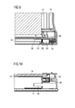
- FIG 9 illustrates a partial sectional front view of the cover frame 16 in the mounted state at the door column 10 of the door according to the preferred embodiment of the present invention.
- the first snap-in mechanism is activated, since the first hook element 24 is connected to the first lug element 26.
- the cover frame 16 is fastened at the door column 10 by the first snap-in mechanism.
- the second snap-in mechanism is deactivated, since the second hook element 28 is not connected to the second lug element 30.
- FIG 10 illustrates a sectional side view of the cover frame 16 in the mounted state at the door column of the door according to the preferred embodiment of the present invention.
- FIG 10 clarifies that the inner door panel 14 is clamped by the cover frame 16 in the mounted state.
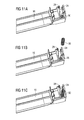
- FIG 11 illustrates three partial detailed perspective views of the cover frame 16 in a demounted state for the door according to the preferred embodiment of the present invention.
- FIG 11 shows the lower side of an end portion of the cover frame 16. The lower side of said end portion is provided to be connected to the upper end of one of the door columns 10.
- FIG 11 clarifies the arrangement of the spring element 32 within the cover frame 16.
- FIG 11 includes the detailed perspective views FIG 11A, FIG 11B and FIG 11C .
- FIG 11A shows the cover frame 16 without the spring element 32.
- the cover frame 16 includes a pin element 36 for receiving the spring element 32.
- FIG 11B illustrates the cover frame 16 and the spring element 32, wherein the spring element 32 is displaced along its longitudinal axis in relation to its provided position at the pin element 36.
- FIG 11C shows the cover frame 16 and the spring element 32, wherein the spring element 32 is placed in the provided position.
- the pin element 36 extends into a part of the spring element 32.
- the spring element 32 is clamped between the pin element 36 of the cover frame 16 and the receiving element 34 of the door column 10 in the mounted state as well as in the intermediate state.
Landscapes
- Engineering & Computer Science (AREA)
- Chemical & Material Sciences (AREA)
- Combustion & Propulsion (AREA)
- Mechanical Engineering (AREA)
- General Engineering & Computer Science (AREA)
- Casings For Electric Apparatus (AREA)
- Securing Of Glass Panes Or The Like (AREA)
- Wing Frames And Configurations (AREA)
- Packaging Of Machine Parts And Wound Products (AREA)
Abstract


Description
- The present invention relates to a door for a domestic appliance according to the preamble of claim 1. Further, the present invention relates to a domestic appliance with at least one door.
- Domestic appliances, in particular cooking ovens, comprise doors with several door panels. The door panels are typically transparent in order to allow the intervisibility inside the domestic appliance. Between the door panels an air stream may be provided for cooling or heating purposes. If the domestic appliance generates high temperatures, then the door panels should limit the temperatures at the outer side of the door.
- Sometimes the door panels should be removable or exchangeable. In particular an inner door panel of a cooking oven should be removable for cleaning. Normally the door panels can be removed, after at least one frame element of the door frame has been removed. Further, tools are required in order to remove the door panel.
- It is an object of the present invention to provide an improved door for a domestic appliance, which allows an easy removal or exchange of at least the inner door panel.
- The object of the present invention is achieved by a door for a domestic appliance according to claim 1.
- According to the present invention in an intermediate state the cover frame is fastened at the door columns in another position as in the mounted state, so that the inner door panel is removable from the inner sides of the door columns.
- The cover frame can be displaced between two positions with respect to the door columns, wherein the cover frame is fastened at the door columns in both positions. In the one position of the cover frame the inner door panel is in a stable state. In the other position of the cover frame the inner door panel is removable, although the cover frame is still fastened at the door columns. Thus, only the door panel itself has to be removed, but not further part of the door. The cover frame must be only displaced.
- According to a preferred embodiment of the present invention in the mounted state the inner door panel is clamped between the cover frame and clamping elements arranged at the lower portions of each door columns.
- Preferably, a first snap-in mechanism is provided between the cover frame and the door columns for fastening the cover frame at the door columns in the mounted state. In general, between the cover frame and the door columns are such fastening elements, which can be released and connected the user without any tools.
- In a similar way, a second snap-in mechanism is provided between the cover frame and the door columns for fastening the cover frame at the door columns in the intermediate state.
- For example, the first and second snap-in mechanisms comprise at least one hook element and at least one lug element in each case. The hook element can be released by pressing a releasing element. In particular, the releasing element and the hook element form a single-piece part. Alternatively, the releasing element may be a separate part besides the hook element.
- In particular, the hook element is arranged at the cover frame and the corresponding lug element is arranged at the door column.
- Alternatively, the hook element is arranged at the door column and the corresponding lug element is arranged at the cover frame.
- Preferably, at least one spring element is arranged between the cover frame and the door column in each case. For example, the spring element includes at least one coil spring.
- Further, the door comprises at least one central door panel arranged between the outer door panel and the inner door panel. For example, the at least one central door panel is arranged between the both door columns. Also the central door panel may be removed, when the cover frame is in the intermediate state.
- At last the present invention relates to a domestic appliance comprising at least one door as described above.
- Novel and inventive features of the present invention are set forth in the appended claims.
- The present invention will be described in further detail with reference to the drawings, in which
- FIG 1
- illustrates three perspective views of different states of a door for a domestic appliance according to a preferred embodiment of the present invention,
- FIG 2
- illustrates three detailed perspective views of the different states of the door for the domestic appliance according to the preferred embodiment of the present invention,
- FIG 3
- illustrates a perspective view of a demounted state of a cover frame for the door according to the preferred embodiment of the present invention,
- FIG 4
- illustrates a detailed perspective view of the demounted state of the cover frame for the door according to the preferred embodiment of the present invention,
- FIG 5
- illustrates a detailed perspective view of a top side of a door column at the door according to the preferred embodiment of the present invention,
- FIG 6
- illustrates a detailed perspective view of the top side of the door column with a spring element at the door according to the preferred embodiment of the present invention,
- FIG 7
- illustrates a partial sectional front view of a cover frame in an intermediate state at the door column of the door according to the preferred embodiment of the present invention,
- FIG 8
- illustrates a sectional side view of the cover frame in the intermediate state at the door column of the door according to the preferred embodiment of the present invention,
- FIG 9
- illustrates a partial sectional front view of the cover frame in the mounted state at the door column of the door according to the preferred embodiment of the present invention,
- FIG 10
- illustrates a sectional side view of the cover frame in the mounted state at the door column of the door accord- ing to the preferred embodiment of the present invention, and
- FIG 11
- illustrates three partial detailed perspective views of the cover frame in a demounted state for the door according to the preferred embodiment of the present invention.
-
FIG 1 illustrates three perspective views of different states of a door for a domestic appliance according to a preferred embodiment of the present invention.FIG 1 includes the perspective viewsFIG 1A, FIG 1B and FIG 1C . -
FIG 1 shows the door in a horizontal position. In a closed state of the domestic appliance the door is arranged vertically at said domestic appliance. In an open state the door is substantially in the horizontal position. Geometric relationships, like "high", "low", "left" or "right", in this description relate to the door in the vertical state. - The door comprises two
door columns 10, anouter door panel 12, aninner door panel 14, acover frame 16 and adoor handle 18. The bothdoor columns 10 are arranged at the left hand side and at the right hand side of the door. Thedoor columns 10 are longitudinal profile elements. In the closed state of the door thedoor columns 10 are arranged vertically. - The
outer door panel 12 is attached at the long front sides of thedoor columns 10. Theouter door panel 12 covers thedoor columns 10 completely. Adoor handle 18 is attached at the outer side of theouter door panel 12. - The
inner door panel 14 is attached at the long rear sides of thedoor columns 10. The area of theinner door panel 14 is smaller than the area of theouter door panel 12. A clampingelement 20 is arranged at the lower end of eachdoor column 10. - The clamping
element 20 is provided for clamping theinner door panel 14 between thecover frame 16 and said clampingelements 20. - In
FIG 1A thecover frame 16 is in a mounted state. Thecover frame 16 is snapped-in at the upper ends of thedoor columns 10. Theinner door panel 14 is clamped between thecover frame 16 and the both clampingelements 20. - In
FIG 1B thecover frame 16 is an intermediate state. Thecover frame 16 is snapped-in at thedoor columns 10 in a higher position as in the mounted state. Theinner door panel 14 is lying on the rear sides of thedoor columns 10. Thus, theinner door panel 14 is now removable and can be picked-up by the user. - In
FIG 1C thecover frame 16 is the intermediate state. Theinner door panel 14 is just removed from the rear sides of thedoor columns 10. In this intermediate state theinner door panel 14 can be removed from the door, but thecover frame 16 is still fastened at thedoor columns 10. -
FIG 2 illustrates three detailed perspective views of the different states of the door for the domestic appliance according to the preferred embodiment of the present invention.FIG 2 includes the perspective viewsFIG 2A, FIG 2B and FIG 2C . - The detailed perspective views show an upper left corner of the door.
FIG 2A, FIG 2B and FIG 2C correspond withFIG 1A, FIG 1B and FIG 1C , respectively. Thus,FIG 2A shows the mounted state of thecover frame 16, andFIG 2B and FIG 2C show the intermediate state of thecover frame 16. - A releasing
element 22 is arranged at the outer side of thecover frame 16. By pressing the releasing element 22 a first snap-in mechanism between thecover frame 16 and thedoor column 10 is disconnected. The first snap-in mechanism connects thecover frame 16 to thedoor column 10 in the mounted state. InFIG 1A the first snap-in mechanism is activated. - A second snap-in mechanism is provided for connecting the
cover frame 16 to thedoor column 10 in the intermediate state. InFIG 1B and FIG 1C the second snap-in mechanism is activated. The second snap-in mechanism fixes thecover frame 16 at thedoor column 10, wherein theinner door panel 14 can be removed. -
FIG 3 illustrates a perspective view of a demounted state of thecover frame 16 for the door according to the preferred embodiment of the present invention. - In
FIG 3 thedoor frame 16 is completely removed from the door and from thedoor columns 10. Theinner door panel 14 is lying on thedoor columns 10 without a stable fixation. - Between the
cover frame 16 and each of the door columns 10 aspring element 32 is shown. Thespring element 32 is provided as an elastic member between thecover frame 16 and thedoor column 10 in order to support the first snap-in mechanism. - In this example two
central door panels 38 are arranged between thedoor columns 10. Further, thecentral door panels 38 are arranged between theouter door panel 12 and theinner door panel 14. -
FIG 4 illustrates a detailed perspective view of the demounted state of thecover frame 16 for the door according to the preferred embodiment of the present invention.FIG 4 shows in detail thecover frame 16, thedoor column 10 and thespring element 32. A receivingelement 34 is arranged at the top side of thedoor column 10. The receivingelement 34 is provided for receiving thespring element 32. -
FIG 5 illustrates a detailed perspective view of a top side of thedoor column 16 at the door according to the preferred embodiment of the present invention. The receivingelement 34 is complementary to the end portion of thespring element 32. -
FIG 6 illustrates a detailed perspective view of the top side of thedoor column 16 with thespring element 32 for the door according to the preferred embodiment of the present invention. InFIG 6 thespring element 32 is inserted in the receivingelement 34. -
FIG 7 illustrates a partial sectional front view of thecover frame 16 in the intermediate state at thedoor column 10 of the door according to the preferred embodiment of the present invention. - The
cover frame 16 comprises afirst hook element 24 and asecond hook element 28. Thedoor column 10 comprises afirst lug element 26 and asecond lug element 30. Thefirst hook element 24 and thefirst lug element 26 form the first snap-in mechanism. Thesecond hook element 28 and thesecond lug element 30 form the second snap-in mechanism. - The
first lug element 26 and thesecond lug element 30 are arranged at the upper end of thedoor column 10 at the same level. Thefirst hook element 24 is shorter than thesecond hook element 28. Thus, thesecond hook element 28 can penetrate deeper in to thedoor column 10 than thefirst hook element 24. The second snap-in mechanism is activated, since thesecond hook element 28 is connected to thesecond lug element 30. The first snap-in mechanism is deactivated, since thefirst hook element 24 is not connected to thefirst lug element 26. Thefirst hook element 24 can be operated by touching the releasingelement 22. - The
cover frame 16 is fastened at thedoor column 10 by the second snap-in mechanism. -
FIG 8 illustrates a sectional side view of thecover frame 16 in the intermediate state at thedoor column 10 of the door according to the preferred embodiment of the present invention. - In the intermediate state the
cover frame 16 is fastened at thedoor column 10 by the second snap-in mechanism.FIG 8 clarifies that theinner door panel 14 can be removed in the intermediate state. -
FIG 9 illustrates a partial sectional front view of thecover frame 16 in the mounted state at thedoor column 10 of the door according to the preferred embodiment of the present invention. - In the mounted state the first snap-in mechanism is activated, since the
first hook element 24 is connected to thefirst lug element 26. Thecover frame 16 is fastened at thedoor column 10 by the first snap-in mechanism. Otherwise, the second snap-in mechanism is deactivated, since thesecond hook element 28 is not connected to thesecond lug element 30. -
FIG 10 illustrates a sectional side view of thecover frame 16 in the mounted state at the door column of the door according to the preferred embodiment of the present invention. - In the mounted state the
cover frame 16 is fastened at thedoor column 10 by the first snap-in mechanism.FIG 10 clarifies that theinner door panel 14 is clamped by thecover frame 16 in the mounted state. -
FIG 11 illustrates three partial detailed perspective views of thecover frame 16 in a demounted state for the door according to the preferred embodiment of the present invention. -
FIG 11 shows the lower side of an end portion of thecover frame 16. The lower side of said end portion is provided to be connected to the upper end of one of thedoor columns 10.FIG 11 clarifies the arrangement of thespring element 32 within thecover frame 16.FIG 11 includes the detailed perspective viewsFIG 11A, FIG 11B and FIG 11C . -
FIG 11A shows thecover frame 16 without thespring element 32. Thecover frame 16 includes apin element 36 for receiving thespring element 32. -
FIG 11B illustrates thecover frame 16 and thespring element 32, wherein thespring element 32 is displaced along its longitudinal axis in relation to its provided position at thepin element 36. -
FIG 11C shows thecover frame 16 and thespring element 32, wherein thespring element 32 is placed in the provided position. Thepin element 36 extends into a part of thespring element 32. - The
spring element 32 is clamped between thepin element 36 of thecover frame 16 and the receivingelement 34 of thedoor column 10 in the mounted state as well as in the intermediate state. - Although an illustrative embodiment of the present invention has been described herein with reference to the accompanying drawings, it is to be understood that the present invention is not limited to this precise embodiment, and that various other changes and modifications may be affected therein by one skilled in the art without departing from the scope or spirit of the invention. All such changes and modifications are intended to be included within the scope of the invention as defined by the appended claims.
-
- 10
- door column
- 12
- outer door panel
- 14
- inner door panel
- 16
- cover frame
- 18
- door handle
- 20
- clamping element
- 22
- releasing element
- 24
- first hook element
- 26
- first lug element
- 28
- second hook element
- 30
- second lug element
- 32
- spring element
- 34
- receiving element
- 36
- pin element
- 38
- central door panel
Claims (11)
- A door for a domestic appliance, in particular for a cooking oven, wherein the door comprises:- two door columns (10) on the left hand side and on the right hand side of the door,- an outer door panel (12) at the outer sides of the door columns (10),- an inner door panel (14) at the inner sides of the door columns (10), and- a cover frame (16) for covering the top sides of the inner door panel (14) and the door columns (10), wherein- in a mounted state the cover frame (16) is fastened on the door columns (10), and the inner door panel (14) is clamped by the cover frame (16),characterized in, that
in an intermediate state the cover frame (16) is fastened at the door columns (10) in another position as in the mounted state, so that the inner door panel (14) is removable from the inner sides of the door columns (10). - The door according to claim 1,
characterized in, that
in the mounted state the inner door panel (14) is clamped between the cover frame (16) and clamping elements (20) arranged at the lower portions of each door column (16). - The door according to claim 1 or 2,
characterized in, that
a first snap-in mechanism (24, 28) is provided between the cover frame (16) and the door columns (10) for fastening the cover frame (16) at the door columns (10) in the mounted state. - The door according to any one of the preceding claims,
characterized in, that
a second snap-in mechanism (26, 30) is provided between the cover frame (16) and the door columns (10) for fastening the cover frame (16) at the door columns (10) in the intermediate state. - The door according to claim 3 or 4,
characterized in, that
the first and second snap-in mechanisms comprise at least one hook element (24; 28) and at least one lug element (26; 30) in each case. - The door according to claim 5,
characterized in, that
the hook element (24; 28) is arranged at the cover frame (16) and the corresponding lug element (26; 30) is arranged at the door column (10). - The door according to claim 5 or 6,
characterized in, that
the hook element (24; 28) is arranged at the door column (10) and the corresponding lug element (26; 30) is arranged at the cover frame (16). - The door according to any one of the preceding claims,
characterized in, that
at least one spring element (32) is arranged between the cover frame (16) and the door column (10) in each case. - The door according to any one of the preceding claims,
characterized in, that
the door comprises at least one central door panel (38) arranged between the outer door panel (12) and the inner door panel (14). - The door according to claim 9,
characterized in, that
the at least one central door panel (38) is arranged between the both door columns (10). - A domestic appliance with at least one door,
characterized in, that
the domestic appliance comprises at least one door according to any one of the claims 1 to 10.
Priority Applications (8)
| Application Number | Priority Date | Filing Date | Title |
|---|---|---|---|
| EP10005104.4A EP2386800B1 (en) | 2010-05-14 | 2010-05-14 | A door for a domestic appliance |
| RU2012154073/03A RU2549646C2 (en) | 2010-05-14 | 2011-05-11 | Door for domestic appliance |
| US13/639,904 US9004623B2 (en) | 2010-05-14 | 2011-05-11 | Door for a domestic appliance |
| BR112012029051A BR112012029051A2 (en) | 2010-05-14 | 2011-05-11 | port for a home appliance |
| CN201180021753.5A CN102893092B (en) | 2010-05-14 | 2011-05-11 | A door for a domestic appliance |
| AU2011252415A AU2011252415B2 (en) | 2010-05-14 | 2011-05-11 | A door for a domestic appliance |
| CA 2799064 CA2799064A1 (en) | 2010-05-14 | 2011-05-11 | A door for a domestic appliance |
| PCT/EP2011/002332 WO2011141166A1 (en) | 2010-05-14 | 2011-05-11 | A door for a domestic appliance |
Applications Claiming Priority (1)
| Application Number | Priority Date | Filing Date | Title |
|---|---|---|---|
| EP10005104.4A EP2386800B1 (en) | 2010-05-14 | 2010-05-14 | A door for a domestic appliance |
Publications (2)
| Publication Number | Publication Date |
|---|---|
| EP2386800A1 true EP2386800A1 (en) | 2011-11-16 |
| EP2386800B1 EP2386800B1 (en) | 2016-09-28 |
Family
ID=43003445
Family Applications (1)
| Application Number | Title | Priority Date | Filing Date |
|---|---|---|---|
| EP10005104.4A Not-in-force EP2386800B1 (en) | 2010-05-14 | 2010-05-14 | A door for a domestic appliance |
Country Status (8)
| Country | Link |
|---|---|
| US (1) | US9004623B2 (en) |
| EP (1) | EP2386800B1 (en) |
| CN (1) | CN102893092B (en) |
| AU (1) | AU2011252415B2 (en) |
| BR (1) | BR112012029051A2 (en) |
| CA (1) | CA2799064A1 (en) |
| RU (1) | RU2549646C2 (en) |
| WO (1) | WO2011141166A1 (en) |
Cited By (10)
| Publication number | Priority date | Publication date | Assignee | Title |
|---|---|---|---|---|
| ITRN20120028A1 (en) * | 2012-06-08 | 2013-12-09 | Indesit Co Spa | COOKING OVEN FOR FOODSTUFFS |
| ITPR20120085A1 (en) * | 2012-12-20 | 2014-06-21 | Indesit Co Spa | OVEN FOR COOKING PIETANCES. |
| EP2930437A1 (en) * | 2014-04-08 | 2015-10-14 | Indesit Company S.p.A. | Door for a domestic cooking oven |
| WO2015165499A1 (en) * | 2014-04-29 | 2015-11-05 | Arcelik Anonim Sirketi | Door with improved disassembly/reassembly for use in an oven |
| DE102016224743A1 (en) * | 2016-12-12 | 2018-06-14 | BSH Hausgeräte GmbH | Haushaltsgargerät |
| US10145565B2 (en) | 2014-04-08 | 2018-12-04 | Whirlpool Emea S.P.A. | Door for a domestic cooking oven |
| EP2851622B1 (en) * | 2013-09-19 | 2019-01-16 | Electrolux Appliances Aktiebolag | A holding structure for a first sheet-like element and method of assembling thereof |
| DE102017220216A1 (en) * | 2017-11-14 | 2019-05-16 | BSH Hausgeräte GmbH | Door for a cooking appliance with specific pane holder, as well as cooking appliance |
| WO2020136131A1 (en) * | 2018-12-27 | 2020-07-02 | BSH Hausgeräte GmbH | A door for a household appliance |
| WO2022017791A1 (en) * | 2020-07-22 | 2022-01-27 | BSH Hausgeräte GmbH | Door and domestic cooking device |
Families Citing this family (5)
| Publication number | Priority date | Publication date | Assignee | Title |
|---|---|---|---|---|
| EP2362150B1 (en) | 2010-02-26 | 2017-05-10 | Electrolux Home Products Corporation N.V. | An oven door for a domestic cooking oven |
| DE102012213126B4 (en) * | 2012-07-26 | 2022-11-10 | BSH Hausgeräte GmbH | Door for a household appliance with a latching element and a prestressing element, and an oven with such a door |
| US9084527B2 (en) | 2013-06-24 | 2015-07-21 | Wolf Appliances, Inc. | Door for an appliance |
| CN105317340A (en) * | 2014-08-05 | 2016-02-10 | 广东美的厨房电器制造有限公司 | Oven firedoor and oven |
| CN105411401A (en) * | 2015-12-22 | 2016-03-23 | 广东美的厨房电器制造有限公司 | Door and cooking utensil |
Citations (4)
| Publication number | Priority date | Publication date | Assignee | Title |
|---|---|---|---|---|
| DE29912626U1 (en) * | 1998-07-21 | 1999-09-09 | Unox Spa | Door, in particular for ovens for heating food or the like. |
| DE10336138B3 (en) * | 2003-08-04 | 2004-10-14 | Miele & Cie. Kg | Door for household equipment has clamping parts movable to locking position and panels fitted with play between elastic part and holding part |
| EP1777462A2 (en) * | 2005-10-18 | 2007-04-25 | Unox S.p.A. | Door for food cooking oven |
| DE102006013521A1 (en) * | 2006-03-23 | 2007-11-08 | BSH Bosch und Siemens Hausgeräte GmbH | Door for a domestic appliance such as an oven comprises a support device with a transverse element that braces a front panel and an inner panel |
Family Cites Families (7)
| Publication number | Priority date | Publication date | Assignee | Title |
|---|---|---|---|---|
| JP2682297B2 (en) * | 1991-09-25 | 1997-11-26 | 松下電器産業株式会社 | High frequency heating equipment |
| RU2052175C1 (en) * | 1992-03-11 | 1996-01-10 | Научно-производственное объединение "Сплав" | Household gas stove |
| ITTO20040087A1 (en) * | 2004-02-17 | 2004-05-17 | Itw Ind Componemts S R L | DEVICE FOR QUICK DISPLACEMENT OF THE POSITION IN HEIGHT OF AN INTERNAL PLAN OF A HOME APPLIANCE SUCH AS A REFRIGERATOR OR FREEZER |
| KR101179729B1 (en) * | 2005-03-02 | 2012-09-05 | 삼성전자주식회사 | Oven |
| AU2007201803B2 (en) * | 2006-04-24 | 2009-06-25 | Lg Electronics Inc. | Oven Door |
| KR100774505B1 (en) * | 2006-05-29 | 2007-11-08 | 엘지전자 주식회사 | Door assembly in oven range |
| CN201059646Y (en) * | 2007-06-25 | 2008-05-14 | 陈如金 | Box doors of bake oven |
-
2010
- 2010-05-14 EP EP10005104.4A patent/EP2386800B1/en not_active Not-in-force
-
2011
- 2011-05-11 WO PCT/EP2011/002332 patent/WO2011141166A1/en active Application Filing
- 2011-05-11 CA CA 2799064 patent/CA2799064A1/en not_active Abandoned
- 2011-05-11 RU RU2012154073/03A patent/RU2549646C2/en not_active IP Right Cessation
- 2011-05-11 US US13/639,904 patent/US9004623B2/en not_active Expired - Fee Related
- 2011-05-11 AU AU2011252415A patent/AU2011252415B2/en not_active Ceased
- 2011-05-11 CN CN201180021753.5A patent/CN102893092B/en not_active Expired - Fee Related
- 2011-05-11 BR BR112012029051A patent/BR112012029051A2/en not_active IP Right Cessation
Patent Citations (4)
| Publication number | Priority date | Publication date | Assignee | Title |
|---|---|---|---|---|
| DE29912626U1 (en) * | 1998-07-21 | 1999-09-09 | Unox Spa | Door, in particular for ovens for heating food or the like. |
| DE10336138B3 (en) * | 2003-08-04 | 2004-10-14 | Miele & Cie. Kg | Door for household equipment has clamping parts movable to locking position and panels fitted with play between elastic part and holding part |
| EP1777462A2 (en) * | 2005-10-18 | 2007-04-25 | Unox S.p.A. | Door for food cooking oven |
| DE102006013521A1 (en) * | 2006-03-23 | 2007-11-08 | BSH Bosch und Siemens Hausgeräte GmbH | Door for a domestic appliance such as an oven comprises a support device with a transverse element that braces a front panel and an inner panel |
Cited By (16)
| Publication number | Priority date | Publication date | Assignee | Title |
|---|---|---|---|---|
| ITRN20120028A1 (en) * | 2012-06-08 | 2013-12-09 | Indesit Co Spa | COOKING OVEN FOR FOODSTUFFS |
| EP2672186A1 (en) * | 2012-06-08 | 2013-12-11 | Indesit Company S.p.A. | Oven for cooking food products |
| ITPR20120085A1 (en) * | 2012-12-20 | 2014-06-21 | Indesit Co Spa | OVEN FOR COOKING PIETANCES. |
| WO2014097229A1 (en) * | 2012-12-20 | 2014-06-26 | Indesit Company S.P.A. | Food cooking oven |
| US11112123B2 (en) | 2012-12-20 | 2021-09-07 | Whirlpool Emea S.P.A. | Food cooking oven |
| US10274204B2 (en) | 2012-12-20 | 2019-04-30 | Whirlpool Emea S.P.A. | Food cooking oven |
| EP2851622B1 (en) * | 2013-09-19 | 2019-01-16 | Electrolux Appliances Aktiebolag | A holding structure for a first sheet-like element and method of assembling thereof |
| US10145565B2 (en) | 2014-04-08 | 2018-12-04 | Whirlpool Emea S.P.A. | Door for a domestic cooking oven |
| EP3073199A1 (en) | 2014-04-08 | 2016-09-28 | Indesit Company S.p.A. | Door for a domestic cooking oven |
| EP2930437A1 (en) * | 2014-04-08 | 2015-10-14 | Indesit Company S.p.A. | Door for a domestic cooking oven |
| WO2015165499A1 (en) * | 2014-04-29 | 2015-11-05 | Arcelik Anonim Sirketi | Door with improved disassembly/reassembly for use in an oven |
| DE102016224743A1 (en) * | 2016-12-12 | 2018-06-14 | BSH Hausgeräte GmbH | Haushaltsgargerät |
| EP3333489B1 (en) | 2016-12-12 | 2020-05-20 | BSH Hausgeräte GmbH | Household cooking appliance |
| DE102017220216A1 (en) * | 2017-11-14 | 2019-05-16 | BSH Hausgeräte GmbH | Door for a cooking appliance with specific pane holder, as well as cooking appliance |
| WO2020136131A1 (en) * | 2018-12-27 | 2020-07-02 | BSH Hausgeräte GmbH | A door for a household appliance |
| WO2022017791A1 (en) * | 2020-07-22 | 2022-01-27 | BSH Hausgeräte GmbH | Door and domestic cooking device |
Also Published As
| Publication number | Publication date |
|---|---|
| US20130049559A1 (en) | 2013-02-28 |
| AU2011252415A1 (en) | 2012-12-20 |
| WO2011141166A1 (en) | 2011-11-17 |
| BR112012029051A2 (en) | 2016-08-02 |
| CN102893092A (en) | 2013-01-23 |
| EP2386800B1 (en) | 2016-09-28 |
| US9004623B2 (en) | 2015-04-14 |
| RU2549646C2 (en) | 2015-04-27 |
| RU2012154073A (en) | 2014-06-20 |
| AU2011252415B2 (en) | 2015-01-22 |
| CA2799064A1 (en) | 2011-11-17 |
| CN102893092B (en) | 2015-06-10 |
Similar Documents
| Publication | Publication Date | Title |
|---|---|---|
| US9004623B2 (en) | Door for a domestic appliance | |
| US7122765B2 (en) | Electric oven | |
| US11168892B2 (en) | Household cooking appliance | |
| US9372003B2 (en) | Spring clip attachment for a surface cooking module of a household cooking appliance | |
| EP2400226A1 (en) | Cooking device door | |
| EP2938930B1 (en) | A door comprising detachable panels and an oven wherein the door is used | |
| US20140283814A1 (en) | Appliance shelving system | |
| EP2731404A1 (en) | An oven door for a microwave oven or a multifunctional oven with microwave heating function | |
| EP2314931B1 (en) | A bearing structure for a casing of a domestic appliance | |
| WO2015165499A1 (en) | Door with improved disassembly/reassembly for use in an oven | |
| EP2868981A1 (en) | A door for a domestic appliance | |
| EP2378946A1 (en) | A household appliance comprising a sliding decorative panel on its door | |
| WO2007054773A3 (en) | Stand-alone control panel for household appliances | |
| EP2672186B1 (en) | Oven for cooking food products | |
| EP2360308B1 (en) | A control panel for a household appliance | |
| CN108700367B (en) | Household appliance device | |
| AU2016296049B2 (en) | Oven door for an oven cavity of a cooking oven | |
| JP6137940B2 (en) | Cooker | |
| EP2090831A1 (en) | Oven door | |
| WO2015096865A1 (en) | Door for use in a household appliance and household appliance having the same | |
| CN113195978A (en) | Door for a domestic appliance | |
| EP2390584A1 (en) | Cabinet for a domestic appliance | |
| KR100722054B1 (en) | A structure of door for oven | |
| JP2008281273A (en) | Heating cooker | |
| WO2008080961A2 (en) | A household appliance |
Legal Events
| Date | Code | Title | Description |
|---|---|---|---|
| 17P | Request for examination filed |
Effective date: 20110303 |
|
| AK | Designated contracting states |
Kind code of ref document: A1 Designated state(s): AL AT BE BG CH CY CZ DE DK EE ES FI FR GB GR HR HU IE IS IT LI LT LU LV MC MK MT NL NO PL PT RO SE SI SK SM TR |
|
| AX | Request for extension of the european patent |
Extension state: BA ME RS |
|
| PUAI | Public reference made under article 153(3) epc to a published international application that has entered the european phase |
Free format text: ORIGINAL CODE: 0009012 |
|
| 17Q | First examination report despatched |
Effective date: 20121205 |
|
| GRAP | Despatch of communication of intention to grant a patent |
Free format text: ORIGINAL CODE: EPIDOSNIGR1 |
|
| INTG | Intention to grant announced |
Effective date: 20151104 |
|
| GRAP | Despatch of communication of intention to grant a patent |
Free format text: ORIGINAL CODE: EPIDOSNIGR1 |
|
| INTG | Intention to grant announced |
Effective date: 20160520 |
|
| GRAS | Grant fee paid |
Free format text: ORIGINAL CODE: EPIDOSNIGR3 |
|
| GRAA | (expected) grant |
Free format text: ORIGINAL CODE: 0009210 |
|
| AK | Designated contracting states |
Kind code of ref document: B1 Designated state(s): AL AT BE BG CH CY CZ DE DK EE ES FI FR GB GR HR HU IE IS IT LI LT LU LV MC MK MT NL NO PL PT RO SE SI SK SM TR |
|
| REG | Reference to a national code |
Ref country code: GB Ref legal event code: FG4D |
|
| REG | Reference to a national code |
Ref country code: CH Ref legal event code: EP |
|
| REG | Reference to a national code |
Ref country code: AT Ref legal event code: REF Ref document number: 833112 Country of ref document: AT Kind code of ref document: T Effective date: 20161015 |
|
| REG | Reference to a national code |
Ref country code: IE Ref legal event code: FG4D |
|
| REG | Reference to a national code |
Ref country code: DE Ref legal event code: R096 Ref document number: 602010036696 Country of ref document: DE |
|
| REG | Reference to a national code |
Ref country code: LT Ref legal event code: MG4D |
|
| PG25 | Lapsed in a contracting state [announced via postgrant information from national office to epo] |
Ref country code: LT Free format text: LAPSE BECAUSE OF FAILURE TO SUBMIT A TRANSLATION OF THE DESCRIPTION OR TO PAY THE FEE WITHIN THE PRESCRIBED TIME-LIMIT Effective date: 20160928 Ref country code: NO Free format text: LAPSE BECAUSE OF FAILURE TO SUBMIT A TRANSLATION OF THE DESCRIPTION OR TO PAY THE FEE WITHIN THE PRESCRIBED TIME-LIMIT Effective date: 20161228 Ref country code: FI Free format text: LAPSE BECAUSE OF FAILURE TO SUBMIT A TRANSLATION OF THE DESCRIPTION OR TO PAY THE FEE WITHIN THE PRESCRIBED TIME-LIMIT Effective date: 20160928 Ref country code: HR Free format text: LAPSE BECAUSE OF FAILURE TO SUBMIT A TRANSLATION OF THE DESCRIPTION OR TO PAY THE FEE WITHIN THE PRESCRIBED TIME-LIMIT Effective date: 20160928 |
|
| REG | Reference to a national code |
Ref country code: NL Ref legal event code: MP Effective date: 20160928 |
|
| REG | Reference to a national code |
Ref country code: AT Ref legal event code: MK05 Ref document number: 833112 Country of ref document: AT Kind code of ref document: T Effective date: 20160928 |
|
| PG25 | Lapsed in a contracting state [announced via postgrant information from national office to epo] |
Ref country code: SE Free format text: LAPSE BECAUSE OF FAILURE TO SUBMIT A TRANSLATION OF THE DESCRIPTION OR TO PAY THE FEE WITHIN THE PRESCRIBED TIME-LIMIT Effective date: 20160928 Ref country code: GR Free format text: LAPSE BECAUSE OF FAILURE TO SUBMIT A TRANSLATION OF THE DESCRIPTION OR TO PAY THE FEE WITHIN THE PRESCRIBED TIME-LIMIT Effective date: 20161229 Ref country code: LV Free format text: LAPSE BECAUSE OF FAILURE TO SUBMIT A TRANSLATION OF THE DESCRIPTION OR TO PAY THE FEE WITHIN THE PRESCRIBED TIME-LIMIT Effective date: 20160928 Ref country code: NL Free format text: LAPSE BECAUSE OF FAILURE TO SUBMIT A TRANSLATION OF THE DESCRIPTION OR TO PAY THE FEE WITHIN THE PRESCRIBED TIME-LIMIT Effective date: 20160928 |
|
| PG25 | Lapsed in a contracting state [announced via postgrant information from national office to epo] |
Ref country code: EE Free format text: LAPSE BECAUSE OF FAILURE TO SUBMIT A TRANSLATION OF THE DESCRIPTION OR TO PAY THE FEE WITHIN THE PRESCRIBED TIME-LIMIT Effective date: 20160928 Ref country code: RO Free format text: LAPSE BECAUSE OF FAILURE TO SUBMIT A TRANSLATION OF THE DESCRIPTION OR TO PAY THE FEE WITHIN THE PRESCRIBED TIME-LIMIT Effective date: 20160928 |
|
| REG | Reference to a national code |
Ref country code: FR Ref legal event code: PLFP Year of fee payment: 8 |
|
| PG25 | Lapsed in a contracting state [announced via postgrant information from national office to epo] |
Ref country code: ES Free format text: LAPSE BECAUSE OF FAILURE TO SUBMIT A TRANSLATION OF THE DESCRIPTION OR TO PAY THE FEE WITHIN THE PRESCRIBED TIME-LIMIT Effective date: 20160928 Ref country code: AT Free format text: LAPSE BECAUSE OF FAILURE TO SUBMIT A TRANSLATION OF THE DESCRIPTION OR TO PAY THE FEE WITHIN THE PRESCRIBED TIME-LIMIT Effective date: 20160928 Ref country code: PL Free format text: LAPSE BECAUSE OF FAILURE TO SUBMIT A TRANSLATION OF THE DESCRIPTION OR TO PAY THE FEE WITHIN THE PRESCRIBED TIME-LIMIT Effective date: 20160928 Ref country code: CZ Free format text: LAPSE BECAUSE OF FAILURE TO SUBMIT A TRANSLATION OF THE DESCRIPTION OR TO PAY THE FEE WITHIN THE PRESCRIBED TIME-LIMIT Effective date: 20160928 Ref country code: BG Free format text: LAPSE BECAUSE OF FAILURE TO SUBMIT A TRANSLATION OF THE DESCRIPTION OR TO PAY THE FEE WITHIN THE PRESCRIBED TIME-LIMIT Effective date: 20161228 Ref country code: SM Free format text: LAPSE BECAUSE OF FAILURE TO SUBMIT A TRANSLATION OF THE DESCRIPTION OR TO PAY THE FEE WITHIN THE PRESCRIBED TIME-LIMIT Effective date: 20160928 Ref country code: IS Free format text: LAPSE BECAUSE OF FAILURE TO SUBMIT A TRANSLATION OF THE DESCRIPTION OR TO PAY THE FEE WITHIN THE PRESCRIBED TIME-LIMIT Effective date: 20170128 Ref country code: SK Free format text: LAPSE BECAUSE OF FAILURE TO SUBMIT A TRANSLATION OF THE DESCRIPTION OR TO PAY THE FEE WITHIN THE PRESCRIBED TIME-LIMIT Effective date: 20160928 Ref country code: BE Free format text: LAPSE BECAUSE OF FAILURE TO SUBMIT A TRANSLATION OF THE DESCRIPTION OR TO PAY THE FEE WITHIN THE PRESCRIBED TIME-LIMIT Effective date: 20160928 Ref country code: PT Free format text: LAPSE BECAUSE OF FAILURE TO SUBMIT A TRANSLATION OF THE DESCRIPTION OR TO PAY THE FEE WITHIN THE PRESCRIBED TIME-LIMIT Effective date: 20170130 |
|
| REG | Reference to a national code |
Ref country code: DE Ref legal event code: R097 Ref document number: 602010036696 Country of ref document: DE |
|
| PG25 | Lapsed in a contracting state [announced via postgrant information from national office to epo] |
Ref country code: DK Free format text: LAPSE BECAUSE OF FAILURE TO SUBMIT A TRANSLATION OF THE DESCRIPTION OR TO PAY THE FEE WITHIN THE PRESCRIBED TIME-LIMIT Effective date: 20160928 |
|
| PGFP | Annual fee paid to national office [announced via postgrant information from national office to epo] |
Ref country code: FR Payment date: 20170523 Year of fee payment: 8 Ref country code: DE Payment date: 20170523 Year of fee payment: 8 |
|
| PLBE | No opposition filed within time limit |
Free format text: ORIGINAL CODE: 0009261 |
|
| STAA | Information on the status of an ep patent application or granted ep patent |
Free format text: STATUS: NO OPPOSITION FILED WITHIN TIME LIMIT |
|
| PG25 | Lapsed in a contracting state [announced via postgrant information from national office to epo] |
Ref country code: LU Free format text: LAPSE BECAUSE OF NON-PAYMENT OF DUE FEES Effective date: 20170531 |
|
| PGFP | Annual fee paid to national office [announced via postgrant information from national office to epo] |
Ref country code: IT Payment date: 20170526 Year of fee payment: 8 |
|
| 26N | No opposition filed |
Effective date: 20170629 |
|
| PG25 | Lapsed in a contracting state [announced via postgrant information from national office to epo] |
Ref country code: SI Free format text: LAPSE BECAUSE OF FAILURE TO SUBMIT A TRANSLATION OF THE DESCRIPTION OR TO PAY THE FEE WITHIN THE PRESCRIBED TIME-LIMIT Effective date: 20160928 |
|
| REG | Reference to a national code |
Ref country code: CH Ref legal event code: PL |
|
| GBPC | Gb: european patent ceased through non-payment of renewal fee |
Effective date: 20170514 |
|
| PG25 | Lapsed in a contracting state [announced via postgrant information from national office to epo] |
Ref country code: MC Free format text: LAPSE BECAUSE OF FAILURE TO SUBMIT A TRANSLATION OF THE DESCRIPTION OR TO PAY THE FEE WITHIN THE PRESCRIBED TIME-LIMIT Effective date: 20160928 |
|
| REG | Reference to a national code |
Ref country code: IE Ref legal event code: MM4A |
|
| PG25 | Lapsed in a contracting state [announced via postgrant information from national office to epo] |
Ref country code: CH Free format text: LAPSE BECAUSE OF NON-PAYMENT OF DUE FEES Effective date: 20170531 Ref country code: LI Free format text: LAPSE BECAUSE OF NON-PAYMENT OF DUE FEES Effective date: 20170531 |
|
| PG25 | Lapsed in a contracting state [announced via postgrant information from national office to epo] |
Ref country code: LU Free format text: LAPSE BECAUSE OF NON-PAYMENT OF DUE FEES Effective date: 20170514 |
|
| PG25 | Lapsed in a contracting state [announced via postgrant information from national office to epo] |
Ref country code: IE Free format text: LAPSE BECAUSE OF NON-PAYMENT OF DUE FEES Effective date: 20170514 Ref country code: GB Free format text: LAPSE BECAUSE OF NON-PAYMENT OF DUE FEES Effective date: 20170514 |
|
| PG25 | Lapsed in a contracting state [announced via postgrant information from national office to epo] |
Ref country code: MT Free format text: LAPSE BECAUSE OF NON-PAYMENT OF DUE FEES Effective date: 20170514 |
|
| PG25 | Lapsed in a contracting state [announced via postgrant information from national office to epo] |
Ref country code: AL Free format text: LAPSE BECAUSE OF FAILURE TO SUBMIT A TRANSLATION OF THE DESCRIPTION OR TO PAY THE FEE WITHIN THE PRESCRIBED TIME-LIMIT Effective date: 20160928 |
|
| REG | Reference to a national code |
Ref country code: DE Ref legal event code: R119 Ref document number: 602010036696 Country of ref document: DE |
|
| PG25 | Lapsed in a contracting state [announced via postgrant information from national office to epo] |
Ref country code: IT Free format text: LAPSE BECAUSE OF NON-PAYMENT OF DUE FEES Effective date: 20180514 Ref country code: FR Free format text: LAPSE BECAUSE OF NON-PAYMENT OF DUE FEES Effective date: 20180531 Ref country code: DE Free format text: LAPSE BECAUSE OF NON-PAYMENT OF DUE FEES Effective date: 20181201 |
|
| PG25 | Lapsed in a contracting state [announced via postgrant information from national office to epo] |
Ref country code: HU Free format text: LAPSE BECAUSE OF FAILURE TO SUBMIT A TRANSLATION OF THE DESCRIPTION OR TO PAY THE FEE WITHIN THE PRESCRIBED TIME-LIMIT; INVALID AB INITIO Effective date: 20100514 |
|
| PG25 | Lapsed in a contracting state [announced via postgrant information from national office to epo] |
Ref country code: CY Free format text: LAPSE BECAUSE OF NON-PAYMENT OF DUE FEES Effective date: 20160928 |
|
| PG25 | Lapsed in a contracting state [announced via postgrant information from national office to epo] |
Ref country code: MK Free format text: LAPSE BECAUSE OF FAILURE TO SUBMIT A TRANSLATION OF THE DESCRIPTION OR TO PAY THE FEE WITHIN THE PRESCRIBED TIME-LIMIT Effective date: 20160928 |
|
| PG25 | Lapsed in a contracting state [announced via postgrant information from national office to epo] |
Ref country code: TR Free format text: LAPSE BECAUSE OF FAILURE TO SUBMIT A TRANSLATION OF THE DESCRIPTION OR TO PAY THE FEE WITHIN THE PRESCRIBED TIME-LIMIT Effective date: 20160928 |