EP2400226A1 - Cooking device door - Google Patents
Cooking device door Download PDFInfo
- Publication number
- EP2400226A1 EP2400226A1 EP11156479A EP11156479A EP2400226A1 EP 2400226 A1 EP2400226 A1 EP 2400226A1 EP 11156479 A EP11156479 A EP 11156479A EP 11156479 A EP11156479 A EP 11156479A EP 2400226 A1 EP2400226 A1 EP 2400226A1
- Authority
- EP
- European Patent Office
- Prior art keywords
- profile
- cooking device
- plate
- channel
- door
- Prior art date
- Legal status (The legal status is an assumption and is not a legal conclusion. Google has not performed a legal analysis and makes no representation as to the accuracy of the status listed.)
- Withdrawn
Links
Images


Classifications
-
- F—MECHANICAL ENGINEERING; LIGHTING; HEATING; WEAPONS; BLASTING
- F24—HEATING; RANGES; VENTILATING
- F24C—DOMESTIC STOVES OR RANGES ; DETAILS OF DOMESTIC STOVES OR RANGES, OF GENERAL APPLICATION
- F24C15/00—Details
- F24C15/02—Doors specially adapted for stoves or ranges
- F24C15/04—Doors specially adapted for stoves or ranges with transparent panels
- F24C15/045—Doors specially adapted for stoves or ranges with transparent panels being dismountable, e.g. giving access for cleaning
Definitions
- the present invention relates to cooking devices comprising attachable/detachable plates on the doors thereof.
- Cooking device doors are generally composed of a front plate and other plates fitted to this plate. These plates are made of heat-resistant transparent materials to make the device interior visible. Put differently, making suchlike plates from transparent materials enables user to see the state of a food cooked in the device, without having to open the door of the latter.
- an oven door with a removable front plate of glass is composed of an internal door body made of metal frames and comprising a window.
- resilient retaining elements On the side of the front glass plate facing the internal body is provided resilient retaining elements.
- a cylindrical element to fit into said retaining elements is provided on the side of the internal body conjoining with the front glass plate.
- an angular retaining element provided at the lower part of the front glass plate is fitted into a recessed opening disposed on the internal body.
- the front glass plate now brought to a certain angular position as a result of pulling it with the angular retaining element provided at the lower part, is detached from the internal body. So it becomes possible to detach the front glass plate from the door body without having to dismantle any component from the door. In the method disclosed in the patent document FR2563612 , however, the glass plate may be damaged due to the force exerted to pull the glass plate.
- a cooking device door has been developed with the present invention, which is composed of detachable plates.
- Said door is composed of at least one front plate and at least one inner plate fitted to this plate.
- At the side of the front plate facing the interior of the cooking device is provided at least one body whereto said inner plate is fitted.
- the inner plate is fastened to the front plate by means of at least one upper profile and at least one slot provided on the body.
- At least one end of the upper plate extends towards the body.
- the extension of this profile is introduced into at least one channel provided on said side of the front plate.
- the plates are lifted upward, are thus released from their slots and removed accordingly.
- they are placed into the slots and the upper profile, now open, is pushed so that it slides in the channel by means of the profile extension. In this way, the profile is closed and the plates are fixed.
- the aim of the present invention is to develop a cooking device door composed of easily-dismountable plates.
- a further aim of the present invention is to develop a cooking device door having plates that can be dismounted without having to dismantle any component from the door.
- Cooking device door (K) Upper profile (1) Inner plate (2) Slot (3) Body (4) Side wall (5) Support element (6) Gap (6') Retaining lug (7) Channel (8) Profile extension (9) Recess (10) Stopper (11) Front plate (12)
- the cooking device door (K) illustrated in Figure 1 comprises in general terms at least one front plate (12) and at least one inner plate (2). These plates (2, 12) are made of heat-resistant materials. In order to avoid the need to open the door (K) during a cooking period, these plates (2, 12) can be of transparent materials as well.
- At the side of the front plate (12) facing the interior of the cooking device are provided at least one body (4) and at least one slot (3) disposed on this body (4), as illustrated in detail in Figure 2 .
- the inner plate (2) is fitted to the front plate (12) as a result of fitting the inner plate (2) to this slot (3) provided on the body (4).
- the number of the inner plate (2) is increased, the number of slots (3) is increased also; in dependence on the number of plates (2) (the figures illustrate three inner plates (2) and correspondingly three slots (4) to fit said plates).
- the opposite edge of the inner plate (2) that cannot be fitted into the slot (3), and at least another edge of the plate (2) are fitted to the front plate (12) by means of at least one upper profile (1), and by means of said body (4), respectively.
- At least one end of the upper profile (1) extends towards the body (4).
- the extension (9) of this profile is introduced into at least one channel (8) provided on the side of the front plate (12) facing into the cooking device.
- the profile (1) can be moved on the direction of X-X' in a sliding manner.
- the profile (1) is slid on direction of X and the plate (2) is attached to at least one aperture (6') disposed on at least one support element (6).
- the user wishes to remove the inner plate (2), he/she pulls the upper profile (1) on direction of X'.
- the profile extension (9) extending toward the body (4) is slid in the channel (8) and the profile (1) is brought to its open position (shown in Figure 4 ).
- the inner plate (2) detached from the aperture (6') on the support element (6) can be easily removed from the slot (3) by moving it towards the direction of Y indicated in Figure 5 .
- FIG. 6 A detailed illustration of the profile extension (9) and the channel (8) are given in figures 6 and 7 .
- the profile (1) is pushed in direction of X, so that the profile extension (9) is introduced into the channel (8) in a sliding manner. So the profile (1) comes to its closed position illustrated in Figure 3 .
- the profile (1) is fixed as a result of fitting at least one retaining lug (7) disposed on this extension (9) to at least one recess (10) provided on the body (4).
- the side wall (5) of the profile extension (9) is depressed, such that the retaining lug (7) provided on the profile extension (9) is released from the recess (10).
- the retaining lug (7) is released from the recess (10)
- the upper profile (1) is pulled in direction of X' and brought to its open position.
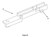
- FIG 8 gives a detailed illustration of the channel (8).
- This channel (8) is fastened to the front plate (12) so that the profile extension (9) can be moved in said channel (8).
- at least one stopper (11) is disposed on at least one side wall of said channel (8). In this manner, the user is enabled to easily remove and attach back the plate (2) without having to dismantle any component from the door (K).
Landscapes
- Engineering & Computer Science (AREA)
- Chemical & Material Sciences (AREA)
- Combustion & Propulsion (AREA)
- Mechanical Engineering (AREA)
- General Engineering & Computer Science (AREA)
- Baking, Grill, Roasting (AREA)
Abstract
A cooking device door (K) has been developed with the present invention, which is composed of detachable plates (2, 12). The cooking device door (K) comprising at least one front plate (12), at least one inner plate (2), fitted to at least one slot (3) disposed on at least one body (4) provided on the side of said plate (12) facing the interior of the cooking device, and at least one movable upper profile (1), fixing the inner plate (2) to the front plate (12), further comprises at least one profile extension (9) extending toward the body (4) on at least one end of the upper profile (1), at least one channel (8), provided on the side of the front plate (12) facing the interior of the cooking device, and in which (8) said profile extension (9) is slid so that the upper profile (1) is moved in direction of X-X', and at least one support element (6), disposed on the upper profile (1), and into which said plate (2) is fitted.
Description
- The present invention relates to cooking devices comprising attachable/detachable plates on the doors thereof.
- Cooking device doors are generally composed of a front plate and other plates fitted to this plate. These plates are made of heat-resistant transparent materials to make the device interior visible. Put differently, making suchlike plates from transparent materials enables user to see the state of a food cooked in the device, without having to open the door of the latter.
- These plates become dirty due to various reasons while foods are cooked in the device. When these plates are fixed to, i.e. not removable from, the door, it becomes difficult to clean the dirt. Thus, oven doors have been developed at which the plates can be removed and then attached back to solve this problem. In such doors developed, however, the user must dismantle some components from the door in order to remove the plates. Therefore, the difficulty in disassembling the plates and assembling them back after cleaning is inconvenient with respect to user comfort.
- In the patent document
FR2563612 FR2563612 - A cooking device door has been developed with the present invention, which is composed of detachable plates. Said door is composed of at least one front plate and at least one inner plate fitted to this plate. At the side of the front plate facing the interior of the cooking device is provided at least one body whereto said inner plate is fitted. The inner plate is fastened to the front plate by means of at least one upper profile and at least one slot provided on the body. At least one end of the upper plate extends towards the body. The extension of this profile is introduced into at least one channel provided on said side of the front plate. Thus, it becomes possible to move the upper profile in a sliding manner. When it is wished to remove the plates, the upper profile is pulled so that the profile extension slides in the channel and the profile becomes open. The plates are lifted upward, are thus released from their slots and removed accordingly. When it is wished to attach back the plates, they are placed into the slots and the upper profile, now open, is pushed so that it slides in the channel by means of the profile extension. In this way, the profile is closed and the plates are fixed.
- The aim of the present invention is to develop a cooking device door composed of easily-dismountable plates.
- A further aim of the present invention is to develop a cooking device door having plates that can be dismounted without having to dismantle any component from the door.
- An exemplary cooking device door and an upper profile movable in a channel according to the present invention are illustrated in annexed figures as described below;
-
Figure 1 is a perspective illustration of a cooking device door. -
Figure 2 provides a close-up view of the detail "A" of said door given inFigure 1 . -
Figure 3 is a detailed illustration of an upper profile in closed position. -
Figure 4 is a detailed illustration of an upper profile in open position. -
Figure 5 is a perspective illustration of a door with the upper profile in open position. -
Figure 6 provides a close-up view of the detail "B" of said door given inFigure 5 . -
Figure 7 provides a close-up view of the detail "C" of said door given inFigure 5 . -
Figure 8 is a perspective illustration of an exemplary channel in which said upper profile is moved. - All the parts illustrated in figures are individually assigned a reference numeral and the corresponding terms of these numbers are listed below.
Cooking device door (K) Upper profile (1) Inner plate (2) Slot (3) Body (4) Side wall (5) Support element (6) Gap (6') Retaining lug (7) Channel (8) Profile extension (9) Recess (10) Stopper (11) Front plate (12) - The cooking device door (K) illustrated in
Figure 1 comprises in general terms at least one front plate (12) and at least one inner plate (2). These plates (2, 12) are made of heat-resistant materials. In order to avoid the need to open the door (K) during a cooking period, these plates (2, 12) can be of transparent materials as well. At the side of the front plate (12) facing the interior of the cooking device (not illustrated in figures) are provided at least one body (4) and at least one slot (3) disposed on this body (4), as illustrated in detail inFigure 2 . The inner plate (2) is fitted to the front plate (12) as a result of fitting the inner plate (2) to this slot (3) provided on the body (4). As the number of the inner plate (2) is increased, the number of slots (3) is increased also; in dependence on the number of plates (2) (the figures illustrate three inner plates (2) and correspondingly three slots (4) to fit said plates). The opposite edge of the inner plate (2) that cannot be fitted into the slot (3), and at least another edge of the plate (2) are fitted to the front plate (12) by means of at least one upper profile (1), and by means of said body (4), respectively. - At least one end of the upper profile (1), which is in closed position in
Figure 3 , extends towards the body (4). The extension (9) of this profile is introduced into at least one channel (8) provided on the side of the front plate (12) facing into the cooking device. Thus, the profile (1) can be moved on the direction of X-X' in a sliding manner. When the inner plate (2) is fitted to the slot (3), the profile (1) is slid on direction of X and the plate (2) is attached to at least one aperture (6') disposed on at least one support element (6). When the user wishes to remove the inner plate (2), he/she pulls the upper profile (1) on direction of X'. The profile extension (9) extending toward the body (4) is slid in the channel (8) and the profile (1) is brought to its open position (shown inFigure 4 ). The inner plate (2) detached from the aperture (6') on the support element (6) can be easily removed from the slot (3) by moving it towards the direction of Y indicated inFigure 5 . - A detailed illustration of the profile extension (9) and the channel (8) are given in
figures 6 and7 . When the plate (2) is fitted to the slot (3), the profile (1) is pushed in direction of X, so that the profile extension (9) is introduced into the channel (8) in a sliding manner. So the profile (1) comes to its closed position illustrated inFigure 3 . The profile (1) is fixed as a result of fitting at least one retaining lug (7) disposed on this extension (9) to at least one recess (10) provided on the body (4). When it is desired to bring the profile (1) to its open position as illustrated inFigure 4 , the side wall (5) of the profile extension (9) is depressed, such that the retaining lug (7) provided on the profile extension (9) is released from the recess (10). When the retaining lug (7) is released from the recess (10), the upper profile (1) is pulled in direction of X' and brought to its open position. -
Figure 8 gives a detailed illustration of the channel (8). This channel (8) is fastened to the front plate (12) so that the profile extension (9) can be moved in said channel (8). In order to prevent the profile (1) extension (9) moving in said channel (8) from coming out of the channel when the profile is pulled in direction of X' in order to bring it to its open position, at least one stopper (11) is disposed on at least one side wall of said channel (8). In this manner, the user is enabled to easily remove and attach back the plate (2) without having to dismantle any component from the door (K).
Claims (5)
- A cooking device door (K) comprising at least one front plate (12); at least one inner plate (2), fitted to at least one slot (3) disposed on at least one body (4) provided on the side of said plate (12) facing the interior of the cooking device; and at least one upper profile (1), fixing the opposite edge of the inner plate (2) not fitted to the slot (3) to the front plate (12), characterized by further comprising- at least one profile extension (9) extending toward the body (4) on at least one end of the upper profile (1),- at least one channel (8), provided on the side of the front plate (12) facing the interior of the cooking device, and in which (8) said upper profile (1) is moved in direction of X-X' in a sliding manner, as a result of introducing said profile extension (9) therein, and- at least one support element (6) with at least one aperture (6'), disposed on the upper profile (1), and into which said plate (2) is fitted.
- The cooking device door (K) according to Claim 1, characterized by comprising at least one recess (10) disposed on said body (4).
- The cooking device door (K) according to Claim 2, characterized by comprising at least one retaining lug (7) disposed on at least one side wall (5) of said profile extension (9), said retaining lug (7) being fitted to said recess (10) disposed on the body (4) so as to fix the upper profile (1).
- The cooking device door (K) according to Claim 1, characterized by comprising at least one stopper (11) disposed on at least one side wall of said channel (8), said stopper (11) preventing the upper profile (1) extension (9) moving in said channel (8) from coming out of the channel (8) when the profile (1) is pulled in direction of X'.
- The cooking device door (K) according to Claim 1, characterized in that said plates (2, 12) are made of a heat-resistant transparent material.
Applications Claiming Priority (1)
| Application Number | Priority Date | Filing Date | Title |
|---|---|---|---|
| TR2010/05080A TR201005080A2 (en) | 2010-06-23 | 2010-06-23 | Cooking appliance door. |
Publications (1)
| Publication Number | Publication Date |
|---|---|
| EP2400226A1 true EP2400226A1 (en) | 2011-12-28 |
Family
ID=44526299
Family Applications (1)
| Application Number | Title | Priority Date | Filing Date |
|---|---|---|---|
| EP11156479A Withdrawn EP2400226A1 (en) | 2010-06-23 | 2011-03-01 | Cooking device door |
Country Status (2)
| Country | Link |
|---|---|
| EP (1) | EP2400226A1 (en) |
| TR (1) | TR201005080A2 (en) |
Cited By (12)
| Publication number | Priority date | Publication date | Assignee | Title |
|---|---|---|---|---|
| ITRN20120028A1 (en) * | 2012-06-08 | 2013-12-09 | Indesit Co Spa | COOKING OVEN FOR FOODSTUFFS |
| DE102012213126A1 (en) * | 2012-07-26 | 2014-01-30 | BSH Bosch und Siemens Hausgeräte GmbH | Door for household appliance, particularly oven, has pretensioning element which is formed, through which locking element of door cover is pressed in position at door profile |
| DE102012217355A1 (en) * | 2012-09-26 | 2014-03-27 | BSH Bosch und Siemens Hausgeräte GmbH | Door for a household appliance and household appliance for preparing food with a door |
| WO2014102116A1 (en) | 2012-12-28 | 2014-07-03 | Arcelik Anonim Sirketi | A door comprising detachable panels and an oven wherein the door is used |
| CN104847198A (en) * | 2015-03-31 | 2015-08-19 | 广东美的厨房电器制造有限公司 | Clamping fastener installation structure, clamping fastener assembly and household electrical appliance |
| US20150308695A1 (en) * | 2014-04-08 | 2015-10-29 | Indesit Company S.P.A. | Door for a domestic cooking oven |
| WO2015165499A1 (en) * | 2014-04-29 | 2015-11-05 | Arcelik Anonim Sirketi | Door with improved disassembly/reassembly for use in an oven |
| EP3333489A1 (en) | 2016-12-12 | 2018-06-13 | BSH Hausgeräte GmbH | Household cooking appliance |
| WO2019091791A1 (en) * | 2017-11-13 | 2019-05-16 | BSH Hausgeräte GmbH | Household appliance having a cooking chamber |
| CN110036242A (en) * | 2016-12-12 | 2019-07-19 | Bsh家用电器有限公司 | Domestic cooking appliance |
| IT201900015767A1 (en) * | 2019-09-06 | 2021-03-06 | Smeg Spa | DOOR OF AN OVEN AND OVEN INCLUDING THIS DOOR |
| WO2022017795A1 (en) * | 2020-07-22 | 2022-01-27 | BSH Hausgeräte GmbH | Door and domestic cooking device |
Citations (5)
| Publication number | Priority date | Publication date | Assignee | Title |
|---|---|---|---|---|
| FR2563612A3 (en) | 1984-04-27 | 1985-10-31 | Licentia Gmbh | Door for cooking and roasting oven of a range |
| DE29912626U1 (en) * | 1998-07-21 | 1999-09-09 | Unox Spa | Door, in particular for ovens for heating food or the like. |
| DE10336138B3 (en) * | 2003-08-04 | 2004-10-14 | Miele & Cie. Kg | Door for household equipment has clamping parts movable to locking position and panels fitted with play between elastic part and holding part |
| EP1777462A2 (en) * | 2005-10-18 | 2007-04-25 | Unox S.p.A. | Door for food cooking oven |
| DE102006013521A1 (en) * | 2006-03-23 | 2007-11-08 | BSH Bosch und Siemens Hausgeräte GmbH | Door for a domestic appliance such as an oven comprises a support device with a transverse element that braces a front panel and an inner panel |
-
2010
- 2010-06-23 TR TR2010/05080A patent/TR201005080A2/en unknown
-
2011
- 2011-03-01 EP EP11156479A patent/EP2400226A1/en not_active Withdrawn
Patent Citations (5)
| Publication number | Priority date | Publication date | Assignee | Title |
|---|---|---|---|---|
| FR2563612A3 (en) | 1984-04-27 | 1985-10-31 | Licentia Gmbh | Door for cooking and roasting oven of a range |
| DE29912626U1 (en) * | 1998-07-21 | 1999-09-09 | Unox Spa | Door, in particular for ovens for heating food or the like. |
| DE10336138B3 (en) * | 2003-08-04 | 2004-10-14 | Miele & Cie. Kg | Door for household equipment has clamping parts movable to locking position and panels fitted with play between elastic part and holding part |
| EP1777462A2 (en) * | 2005-10-18 | 2007-04-25 | Unox S.p.A. | Door for food cooking oven |
| DE102006013521A1 (en) * | 2006-03-23 | 2007-11-08 | BSH Bosch und Siemens Hausgeräte GmbH | Door for a domestic appliance such as an oven comprises a support device with a transverse element that braces a front panel and an inner panel |
Cited By (18)
| Publication number | Priority date | Publication date | Assignee | Title |
|---|---|---|---|---|
| EP2672186A1 (en) * | 2012-06-08 | 2013-12-11 | Indesit Company S.p.A. | Oven for cooking food products |
| ITRN20120028A1 (en) * | 2012-06-08 | 2013-12-09 | Indesit Co Spa | COOKING OVEN FOR FOODSTUFFS |
| DE102012213126A1 (en) * | 2012-07-26 | 2014-01-30 | BSH Bosch und Siemens Hausgeräte GmbH | Door for household appliance, particularly oven, has pretensioning element which is formed, through which locking element of door cover is pressed in position at door profile |
| DE102012213126B4 (en) | 2012-07-26 | 2022-11-10 | BSH Hausgeräte GmbH | Door for a household appliance with a latching element and a prestressing element, and an oven with such a door |
| DE102012217355A1 (en) * | 2012-09-26 | 2014-03-27 | BSH Bosch und Siemens Hausgeräte GmbH | Door for a household appliance and household appliance for preparing food with a door |
| WO2014102116A1 (en) | 2012-12-28 | 2014-07-03 | Arcelik Anonim Sirketi | A door comprising detachable panels and an oven wherein the door is used |
| US10145565B2 (en) * | 2014-04-08 | 2018-12-04 | Whirlpool Emea S.P.A. | Door for a domestic cooking oven |
| US20150308695A1 (en) * | 2014-04-08 | 2015-10-29 | Indesit Company S.P.A. | Door for a domestic cooking oven |
| WO2015165499A1 (en) * | 2014-04-29 | 2015-11-05 | Arcelik Anonim Sirketi | Door with improved disassembly/reassembly for use in an oven |
| CN104847198A (en) * | 2015-03-31 | 2015-08-19 | 广东美的厨房电器制造有限公司 | Clamping fastener installation structure, clamping fastener assembly and household electrical appliance |
| EP3333489A1 (en) | 2016-12-12 | 2018-06-13 | BSH Hausgeräte GmbH | Household cooking appliance |
| CN110036242A (en) * | 2016-12-12 | 2019-07-19 | Bsh家用电器有限公司 | Domestic cooking appliance |
| EP3333489B1 (en) | 2016-12-12 | 2020-05-20 | BSH Hausgeräte GmbH | Household cooking appliance |
| CN110036242B (en) * | 2016-12-12 | 2021-02-05 | Bsh家用电器有限公司 | Household cooking appliance |
| DE102016224743A1 (en) | 2016-12-12 | 2018-06-14 | BSH Hausgeräte GmbH | Haushaltsgargerät |
| WO2019091791A1 (en) * | 2017-11-13 | 2019-05-16 | BSH Hausgeräte GmbH | Household appliance having a cooking chamber |
| IT201900015767A1 (en) * | 2019-09-06 | 2021-03-06 | Smeg Spa | DOOR OF AN OVEN AND OVEN INCLUDING THIS DOOR |
| WO2022017795A1 (en) * | 2020-07-22 | 2022-01-27 | BSH Hausgeräte GmbH | Door and domestic cooking device |
Also Published As
| Publication number | Publication date |
|---|---|
| TR201005080A2 (en) | 2010-12-21 |
Similar Documents
| Publication | Publication Date | Title |
|---|---|---|
| EP2400226A1 (en) | Cooking device door | |
| US9004623B2 (en) | Door for a domestic appliance | |
| US11168892B2 (en) | Household cooking appliance | |
| EP2938930B1 (en) | A door comprising detachable panels and an oven wherein the door is used | |
| KR101588748B1 (en) | oven | |
| US20130118471A1 (en) | Extendable rack mounting system for an oven appliance | |
| DE19954470A1 (en) | Device and method for operating a pyrolysis oven | |
| WO2015165499A1 (en) | Door with improved disassembly/reassembly for use in an oven | |
| US8662066B2 (en) | Closure device associable with an opening of a cooking chamber of an oven with a trolley for the sealed closure of the chamber in the absence of the trolley | |
| JP2007064585A (en) | Heating cooker | |
| EP2672186B1 (en) | Oven for cooking food products | |
| US1979210A (en) | Door mounting | |
| US20100199965A1 (en) | Drawer type cooking device | |
| WO2010078894A3 (en) | Household appliance, in particular oven | |
| EP3120080B1 (en) | A hood with a pull-out steam shield | |
| EP2851622B1 (en) | A holding structure for a first sheet-like element and method of assembling thereof | |
| US11199331B2 (en) | Cooking oven with cavity drawer having movable door | |
| EP2063185A3 (en) | A cooking oven with a cavity and an oven cart | |
| CN206062955U (en) | Baking box hanger and baking oven stove | |
| CN206137885U (en) | Dismantled and assembled lid and electric rice cooker | |
| EP2250441B1 (en) | Door for a baking oven | |
| EP3754262A1 (en) | A door for a household appliance | |
| CN215686962U (en) | Cooking utensil | |
| JP2015075250A (en) | Heating cooker | |
| KR200372475Y1 (en) | Drawer type microwave oven |
Legal Events
| Date | Code | Title | Description |
|---|---|---|---|
| AK | Designated contracting states |
Kind code of ref document: A1 Designated state(s): AL AT BE BG CH CY CZ DE DK EE ES FI FR GB GR HR HU IE IS IT LI LT LU LV MC MK MT NL NO PL PT RO RS SE SI SK SM TR |
|
| AX | Request for extension of the european patent |
Extension state: BA ME |
|
| PUAI | Public reference made under article 153(3) epc to a published international application that has entered the european phase |
Free format text: ORIGINAL CODE: 0009012 |
|
| 17P | Request for examination filed |
Effective date: 20120109 |
|
| 17Q | First examination report despatched |
Effective date: 20130131 |
|
| STAA | Information on the status of an ep patent application or granted ep patent |
Free format text: STATUS: THE APPLICATION IS DEEMED TO BE WITHDRAWN |
|
| 18D | Application deemed to be withdrawn |
Effective date: 20130611 |