EP2385873B1 - Carbonation calcination reaction process for co2 capture using a highly regenerable sorbent - Google Patents
Carbonation calcination reaction process for co2 capture using a highly regenerable sorbent Download PDFInfo
- Publication number
- EP2385873B1 EP2385873B1 EP09828257.7A EP09828257A EP2385873B1 EP 2385873 B1 EP2385873 B1 EP 2385873B1 EP 09828257 A EP09828257 A EP 09828257A EP 2385873 B1 EP2385873 B1 EP 2385873B1
- Authority
- EP
- European Patent Office
- Prior art keywords
- sorbent
- reactor
- hydration
- hydrated
- carbonation
- Prior art date
- Legal status (The legal status is an assumption and is not a legal conclusion. Google has not performed a legal analysis and makes no representation as to the accuracy of the status listed.)
- Active
Links
- 239000002594 sorbent Substances 0.000 title claims description 169
- 238000001354 calcination Methods 0.000 title claims description 36
- 238000006243 chemical reaction Methods 0.000 title description 37
- 238000006703 hydration reaction Methods 0.000 claims description 101
- 230000036571 hydration Effects 0.000 claims description 99
- 238000000034 method Methods 0.000 claims description 90
- 230000008569 process Effects 0.000 claims description 63
- 239000000292 calcium oxide Substances 0.000 claims description 51
- ODINCKMPIJJUCX-UHFFFAOYSA-N calcium oxide Inorganic materials [Ca]=O ODINCKMPIJJUCX-UHFFFAOYSA-N 0.000 claims description 51
- UGFAIRIUMAVXCW-UHFFFAOYSA-N Carbon monoxide Chemical compound [O+]#[C-] UGFAIRIUMAVXCW-UHFFFAOYSA-N 0.000 claims description 37
- 239000003546 flue gas Substances 0.000 claims description 37
- 238000006297 dehydration reaction Methods 0.000 claims description 27
- 239000003245 coal Substances 0.000 claims description 23
- 230000007420 reactivation Effects 0.000 claims description 23
- OKTJSMMVPCPJKN-UHFFFAOYSA-N Carbon Chemical compound [C] OKTJSMMVPCPJKN-UHFFFAOYSA-N 0.000 claims description 19
- 229910052799 carbon Inorganic materials 0.000 claims description 19
- BRPQOXSCLDDYGP-UHFFFAOYSA-N calcium oxide Chemical group [O-2].[Ca+2] BRPQOXSCLDDYGP-UHFFFAOYSA-N 0.000 claims description 17
- 230000018044 dehydration Effects 0.000 claims description 16
- 230000005611 electricity Effects 0.000 claims description 12
- 238000001816 cooling Methods 0.000 claims description 9
- 229910044991 metal oxide Inorganic materials 0.000 claims description 9
- 150000004706 metal oxides Chemical class 0.000 claims description 9
- 230000000887 hydrating effect Effects 0.000 claims description 7
- 239000012530 fluid Substances 0.000 claims description 6
- 230000009919 sequestration Effects 0.000 claims description 5
- 230000005484 gravity Effects 0.000 claims description 3
- 229910000000 metal hydroxide Inorganic materials 0.000 claims 4
- 150000004692 metal hydroxides Chemical class 0.000 claims 4
- 238000004064 recycling Methods 0.000 claims 2
- CURLTUGMZLYLDI-UHFFFAOYSA-N Carbon dioxide Chemical compound O=C=O CURLTUGMZLYLDI-UHFFFAOYSA-N 0.000 description 140
- 229910002092 carbon dioxide Inorganic materials 0.000 description 127
- 239000001569 carbon dioxide Substances 0.000 description 127
- AXCZMVOFGPJBDE-UHFFFAOYSA-L calcium dihydroxide Chemical compound [OH-].[OH-].[Ca+2] AXCZMVOFGPJBDE-UHFFFAOYSA-L 0.000 description 44
- 239000000920 calcium hydroxide Substances 0.000 description 43
- 229910001861 calcium hydroxide Inorganic materials 0.000 description 41
- RAHZWNYVWXNFOC-UHFFFAOYSA-N Sulphur dioxide Chemical compound O=S=O RAHZWNYVWXNFOC-UHFFFAOYSA-N 0.000 description 40
- OYPRJOBELJOOCE-UHFFFAOYSA-N Calcium Chemical compound [Ca] OYPRJOBELJOOCE-UHFFFAOYSA-N 0.000 description 32
- 239000011575 calcium Substances 0.000 description 32
- 229910052791 calcium Inorganic materials 0.000 description 32
- 239000007789 gas Substances 0.000 description 28
- XLYOFNOQVPJJNP-UHFFFAOYSA-N water Substances O XLYOFNOQVPJJNP-UHFFFAOYSA-N 0.000 description 26
- 239000007787 solid Substances 0.000 description 25
- 235000011116 calcium hydroxide Nutrition 0.000 description 24
- 235000008733 Citrus aurantifolia Nutrition 0.000 description 23
- 235000011941 Tilia x europaea Nutrition 0.000 description 23
- 239000004571 lime Substances 0.000 description 23
- VTYYLEPIZMXCLO-UHFFFAOYSA-L Calcium carbonate Chemical compound [Ca+2].[O-]C([O-])=O VTYYLEPIZMXCLO-UHFFFAOYSA-L 0.000 description 22
- 240000006909 Tilia x europaea Species 0.000 description 22
- 230000000694 effects Effects 0.000 description 19
- 230000003071 parasitic effect Effects 0.000 description 17
- 230000009257 reactivity Effects 0.000 description 16
- OSGAYBCDTDRGGQ-UHFFFAOYSA-L calcium sulfate Chemical compound [Ca+2].[O-]S([O-])(=O)=O OSGAYBCDTDRGGQ-UHFFFAOYSA-L 0.000 description 14
- 238000005245 sintering Methods 0.000 description 14
- UFHFLCQGNIYNRP-UHFFFAOYSA-N Hydrogen Chemical compound [H][H] UFHFLCQGNIYNRP-UHFFFAOYSA-N 0.000 description 12
- 238000002485 combustion reaction Methods 0.000 description 12
- 239000001257 hydrogen Substances 0.000 description 12
- 229910052739 hydrogen Inorganic materials 0.000 description 12
- 230000001965 increasing effect Effects 0.000 description 12
- 229910000019 calcium carbonate Inorganic materials 0.000 description 11
- 230000010354 integration Effects 0.000 description 11
- 235000019738 Limestone Nutrition 0.000 description 9
- 238000004519 manufacturing process Methods 0.000 description 9
- 239000012298 atmosphere Substances 0.000 description 8
- 230000007423 decrease Effects 0.000 description 8
- 238000005265 energy consumption Methods 0.000 description 8
- 238000002474 experimental method Methods 0.000 description 8
- 239000006028 limestone Substances 0.000 description 8
- NINIDFKCEFEMDL-UHFFFAOYSA-N Sulfur Chemical compound [S] NINIDFKCEFEMDL-UHFFFAOYSA-N 0.000 description 7
- 229910052717 sulfur Inorganic materials 0.000 description 7
- 239000011593 sulfur Substances 0.000 description 7
- 241000196324 Embryophyta Species 0.000 description 6
- VNWKTOKETHGBQD-UHFFFAOYSA-N methane Chemical compound C VNWKTOKETHGBQD-UHFFFAOYSA-N 0.000 description 6
- 239000000203 mixture Substances 0.000 description 6
- 239000012159 carrier gas Substances 0.000 description 5
- 238000010586 diagram Methods 0.000 description 5
- 238000012360 testing method Methods 0.000 description 5
- 241000183024 Populus tremula Species 0.000 description 4
- 229910052925 anhydrite Inorganic materials 0.000 description 4
- QVGXLLKOCUKJST-UHFFFAOYSA-N atomic oxygen Chemical compound [O] QVGXLLKOCUKJST-UHFFFAOYSA-N 0.000 description 4
- 238000011021 bench scale process Methods 0.000 description 4
- 239000001301 oxygen Substances 0.000 description 4
- 229910052760 oxygen Inorganic materials 0.000 description 4
- 239000000376 reactant Substances 0.000 description 4
- 238000004088 simulation Methods 0.000 description 4
- 230000015572 biosynthetic process Effects 0.000 description 3
- MWUXSHHQAYIFBG-UHFFFAOYSA-N nitrogen oxide Inorganic materials O=[N] MWUXSHHQAYIFBG-UHFFFAOYSA-N 0.000 description 3
- 239000008188 pellet Substances 0.000 description 3
- 239000000843 powder Substances 0.000 description 3
- 238000002203 pretreatment Methods 0.000 description 3
- 238000003303 reheating Methods 0.000 description 3
- 238000011160 research Methods 0.000 description 3
- RWSOTUBLDIXVET-UHFFFAOYSA-N Dihydrogen sulfide Chemical compound S RWSOTUBLDIXVET-UHFFFAOYSA-N 0.000 description 2
- 150000001412 amines Chemical class 0.000 description 2
- 238000013459 approach Methods 0.000 description 2
- 230000001143 conditioned effect Effects 0.000 description 2
- 125000004122 cyclic group Chemical group 0.000 description 2
- 238000000354 decomposition reaction Methods 0.000 description 2
- 238000013461 design Methods 0.000 description 2
- 230000008030 elimination Effects 0.000 description 2
- 238000003379 elimination reaction Methods 0.000 description 2
- 238000005516 engineering process Methods 0.000 description 2
- 239000003344 environmental pollutant Substances 0.000 description 2
- 239000000446 fuel Substances 0.000 description 2
- 238000002309 gasification Methods 0.000 description 2
- 150000004820 halides Chemical class 0.000 description 2
- 238000010438 heat treatment Methods 0.000 description 2
- 239000012535 impurity Substances 0.000 description 2
- 238000002347 injection Methods 0.000 description 2
- 239000007924 injection Substances 0.000 description 2
- VTHJTEIRLNZDEV-UHFFFAOYSA-L magnesium dihydroxide Chemical compound [OH-].[OH-].[Mg+2] VTHJTEIRLNZDEV-UHFFFAOYSA-L 0.000 description 2
- 239000000463 material Substances 0.000 description 2
- 231100000719 pollutant Toxicity 0.000 description 2
- 239000002243 precursor Substances 0.000 description 2
- 239000010453 quartz Substances 0.000 description 2
- 230000008929 regeneration Effects 0.000 description 2
- 238000011069 regeneration method Methods 0.000 description 2
- 230000001105 regulatory effect Effects 0.000 description 2
- VYPSYNLAJGMNEJ-UHFFFAOYSA-N silicon dioxide Inorganic materials O=[Si]=O VYPSYNLAJGMNEJ-UHFFFAOYSA-N 0.000 description 2
- 239000000243 solution Substances 0.000 description 2
- 239000000126 substance Substances 0.000 description 2
- 238000011144 upstream manufacturing Methods 0.000 description 2
- 241001436672 Bhatia Species 0.000 description 1
- UXVMQQNJUSDDNG-UHFFFAOYSA-L Calcium chloride Chemical compound [Cl-].[Cl-].[Ca+2] UXVMQQNJUSDDNG-UHFFFAOYSA-L 0.000 description 1
- FYYHWMGAXLPEAU-UHFFFAOYSA-N Magnesium Chemical compound [Mg] FYYHWMGAXLPEAU-UHFFFAOYSA-N 0.000 description 1
- 240000007313 Tilia cordata Species 0.000 description 1
- 239000001110 calcium chloride Substances 0.000 description 1
- 229910001628 calcium chloride Inorganic materials 0.000 description 1
- 230000015556 catabolic process Effects 0.000 description 1
- 230000001276 controlling effect Effects 0.000 description 1
- 230000003247 decreasing effect Effects 0.000 description 1
- 238000006731 degradation reaction Methods 0.000 description 1
- 239000002274 desiccant Substances 0.000 description 1
- 230000009977 dual effect Effects 0.000 description 1
- 230000002708 enhancing effect Effects 0.000 description 1
- 238000001704 evaporation Methods 0.000 description 1
- 230000008020 evaporation Effects 0.000 description 1
- 239000002803 fossil fuel Substances 0.000 description 1
- 238000004868 gas analysis Methods 0.000 description 1
- 238000000227 grinding Methods 0.000 description 1
- 229910052602 gypsum Inorganic materials 0.000 description 1
- 239000010440 gypsum Substances 0.000 description 1
- 150000004677 hydrates Chemical class 0.000 description 1
- 238000011835 investigation Methods 0.000 description 1
- 239000007788 liquid Substances 0.000 description 1
- 239000011777 magnesium Substances 0.000 description 1
- 229910052749 magnesium Inorganic materials 0.000 description 1
- 238000005259 measurement Methods 0.000 description 1
- 230000007246 mechanism Effects 0.000 description 1
- 238000002156 mixing Methods 0.000 description 1
- 239000003345 natural gas Substances 0.000 description 1
- 239000012299 nitrogen atmosphere Substances 0.000 description 1
- 238000012856 packing Methods 0.000 description 1
- 239000002245 particle Substances 0.000 description 1
- 238000011020 pilot scale process Methods 0.000 description 1
- 230000000750 progressive effect Effects 0.000 description 1
- 238000005086 pumping Methods 0.000 description 1
- 230000035484 reaction time Effects 0.000 description 1
- 230000009467 reduction Effects 0.000 description 1
- 230000004044 response Effects 0.000 description 1
- 230000002441 reversible effect Effects 0.000 description 1
- 239000008247 solid mixture Substances 0.000 description 1
- 239000002904 solvent Substances 0.000 description 1
- 238000001179 sorption measurement Methods 0.000 description 1
- 230000003068 static effect Effects 0.000 description 1
- 238000001991 steam methane reforming Methods 0.000 description 1
- 238000003756 stirring Methods 0.000 description 1
- 238000012546 transfer Methods 0.000 description 1
- 239000002699 waste material Substances 0.000 description 1
Images


Classifications
-
- B—PERFORMING OPERATIONS; TRANSPORTING
- B01—PHYSICAL OR CHEMICAL PROCESSES OR APPARATUS IN GENERAL
- B01D—SEPARATION
- B01D53/00—Separation of gases or vapours; Recovering vapours of volatile solvents from gases; Chemical or biological purification of waste gases, e.g. engine exhaust gases, smoke, fumes, flue gases, aerosols
- B01D53/34—Chemical or biological purification of waste gases
- B01D53/46—Removing components of defined structure
- B01D53/62—Carbon oxides
-
- B—PERFORMING OPERATIONS; TRANSPORTING
- B01—PHYSICAL OR CHEMICAL PROCESSES OR APPARATUS IN GENERAL
- B01D—SEPARATION
- B01D53/00—Separation of gases or vapours; Recovering vapours of volatile solvents from gases; Chemical or biological purification of waste gases, e.g. engine exhaust gases, smoke, fumes, flue gases, aerosols
- B01D53/34—Chemical or biological purification of waste gases
- B01D53/46—Removing components of defined structure
- B01D53/48—Sulfur compounds
- B01D53/50—Sulfur oxides
- B01D53/508—Sulfur oxides by treating the gases with solids
-
- B—PERFORMING OPERATIONS; TRANSPORTING
- B01—PHYSICAL OR CHEMICAL PROCESSES OR APPARATUS IN GENERAL
- B01D—SEPARATION
- B01D53/00—Separation of gases or vapours; Recovering vapours of volatile solvents from gases; Chemical or biological purification of waste gases, e.g. engine exhaust gases, smoke, fumes, flue gases, aerosols
- B01D53/34—Chemical or biological purification of waste gases
- B01D53/96—Regeneration, reactivation or recycling of reactants
-
- B—PERFORMING OPERATIONS; TRANSPORTING
- B01—PHYSICAL OR CHEMICAL PROCESSES OR APPARATUS IN GENERAL
- B01J—CHEMICAL OR PHYSICAL PROCESSES, e.g. CATALYSIS OR COLLOID CHEMISTRY; THEIR RELEVANT APPARATUS
- B01J20/00—Solid sorbent compositions or filter aid compositions; Sorbents for chromatography; Processes for preparing, regenerating or reactivating thereof
- B01J20/02—Solid sorbent compositions or filter aid compositions; Sorbents for chromatography; Processes for preparing, regenerating or reactivating thereof comprising inorganic material
- B01J20/04—Solid sorbent compositions or filter aid compositions; Sorbents for chromatography; Processes for preparing, regenerating or reactivating thereof comprising inorganic material comprising compounds of alkali metals, alkaline earth metals or magnesium
- B01J20/041—Oxides or hydroxides
-
- B—PERFORMING OPERATIONS; TRANSPORTING
- B01—PHYSICAL OR CHEMICAL PROCESSES OR APPARATUS IN GENERAL
- B01J—CHEMICAL OR PHYSICAL PROCESSES, e.g. CATALYSIS OR COLLOID CHEMISTRY; THEIR RELEVANT APPARATUS
- B01J20/00—Solid sorbent compositions or filter aid compositions; Sorbents for chromatography; Processes for preparing, regenerating or reactivating thereof
- B01J20/02—Solid sorbent compositions or filter aid compositions; Sorbents for chromatography; Processes for preparing, regenerating or reactivating thereof comprising inorganic material
- B01J20/04—Solid sorbent compositions or filter aid compositions; Sorbents for chromatography; Processes for preparing, regenerating or reactivating thereof comprising inorganic material comprising compounds of alkali metals, alkaline earth metals or magnesium
- B01J20/043—Carbonates or bicarbonates, e.g. limestone, dolomite, aragonite
-
- B—PERFORMING OPERATIONS; TRANSPORTING
- B01—PHYSICAL OR CHEMICAL PROCESSES OR APPARATUS IN GENERAL
- B01J—CHEMICAL OR PHYSICAL PROCESSES, e.g. CATALYSIS OR COLLOID CHEMISTRY; THEIR RELEVANT APPARATUS
- B01J20/00—Solid sorbent compositions or filter aid compositions; Sorbents for chromatography; Processes for preparing, regenerating or reactivating thereof
- B01J20/30—Processes for preparing, regenerating, or reactivating
- B01J20/34—Regenerating or reactivating
- B01J20/3433—Regenerating or reactivating of sorbents or filter aids other than those covered by B01J20/3408 - B01J20/3425
-
- B—PERFORMING OPERATIONS; TRANSPORTING
- B01—PHYSICAL OR CHEMICAL PROCESSES OR APPARATUS IN GENERAL
- B01J—CHEMICAL OR PHYSICAL PROCESSES, e.g. CATALYSIS OR COLLOID CHEMISTRY; THEIR RELEVANT APPARATUS
- B01J20/00—Solid sorbent compositions or filter aid compositions; Sorbents for chromatography; Processes for preparing, regenerating or reactivating thereof
- B01J20/30—Processes for preparing, regenerating, or reactivating
- B01J20/34—Regenerating or reactivating
- B01J20/3483—Regenerating or reactivating by thermal treatment not covered by groups B01J20/3441 - B01J20/3475, e.g. by heating or cooling
-
- B—PERFORMING OPERATIONS; TRANSPORTING
- B01—PHYSICAL OR CHEMICAL PROCESSES OR APPARATUS IN GENERAL
- B01J—CHEMICAL OR PHYSICAL PROCESSES, e.g. CATALYSIS OR COLLOID CHEMISTRY; THEIR RELEVANT APPARATUS
- B01J20/00—Solid sorbent compositions or filter aid compositions; Sorbents for chromatography; Processes for preparing, regenerating or reactivating thereof
- B01J20/30—Processes for preparing, regenerating, or reactivating
- B01J20/34—Regenerating or reactivating
- B01J20/3491—Regenerating or reactivating by pressure treatment
-
- C—CHEMISTRY; METALLURGY
- C01—INORGANIC CHEMISTRY
- C01F—COMPOUNDS OF THE METALS BERYLLIUM, MAGNESIUM, ALUMINIUM, CALCIUM, STRONTIUM, BARIUM, RADIUM, THORIUM, OR OF THE RARE-EARTH METALS
- C01F11/00—Compounds of calcium, strontium, or barium
- C01F11/02—Oxides or hydroxides
-
- B—PERFORMING OPERATIONS; TRANSPORTING
- B01—PHYSICAL OR CHEMICAL PROCESSES OR APPARATUS IN GENERAL
- B01D—SEPARATION
- B01D2251/00—Reactants
- B01D2251/40—Alkaline earth metal or magnesium compounds
- B01D2251/404—Alkaline earth metal or magnesium compounds of calcium
-
- B—PERFORMING OPERATIONS; TRANSPORTING
- B01—PHYSICAL OR CHEMICAL PROCESSES OR APPARATUS IN GENERAL
- B01D—SEPARATION
- B01D2257/00—Components to be removed
- B01D2257/30—Sulfur compounds
- B01D2257/302—Sulfur oxides
-
- B—PERFORMING OPERATIONS; TRANSPORTING
- B01—PHYSICAL OR CHEMICAL PROCESSES OR APPARATUS IN GENERAL
- B01D—SEPARATION
- B01D2257/00—Components to be removed
- B01D2257/50—Carbon oxides
- B01D2257/504—Carbon dioxide
-
- Y—GENERAL TAGGING OF NEW TECHNOLOGICAL DEVELOPMENTS; GENERAL TAGGING OF CROSS-SECTIONAL TECHNOLOGIES SPANNING OVER SEVERAL SECTIONS OF THE IPC; TECHNICAL SUBJECTS COVERED BY FORMER USPC CROSS-REFERENCE ART COLLECTIONS [XRACs] AND DIGESTS
- Y02—TECHNOLOGIES OR APPLICATIONS FOR MITIGATION OR ADAPTATION AGAINST CLIMATE CHANGE
- Y02C—CAPTURE, STORAGE, SEQUESTRATION OR DISPOSAL OF GREENHOUSE GASES [GHG]
- Y02C20/00—Capture or disposal of greenhouse gases
- Y02C20/40—Capture or disposal of greenhouse gases of CO2
-
- Y—GENERAL TAGGING OF NEW TECHNOLOGICAL DEVELOPMENTS; GENERAL TAGGING OF CROSS-SECTIONAL TECHNOLOGIES SPANNING OVER SEVERAL SECTIONS OF THE IPC; TECHNICAL SUBJECTS COVERED BY FORMER USPC CROSS-REFERENCE ART COLLECTIONS [XRACs] AND DIGESTS
- Y02—TECHNOLOGIES OR APPLICATIONS FOR MITIGATION OR ADAPTATION AGAINST CLIMATE CHANGE
- Y02P—CLIMATE CHANGE MITIGATION TECHNOLOGIES IN THE PRODUCTION OR PROCESSING OF GOODS
- Y02P20/00—Technologies relating to chemical industry
- Y02P20/10—Process efficiency
- Y02P20/129—Energy recovery, e.g. by cogeneration, H2recovery or pressure recovery turbines
-
- Y—GENERAL TAGGING OF NEW TECHNOLOGICAL DEVELOPMENTS; GENERAL TAGGING OF CROSS-SECTIONAL TECHNOLOGIES SPANNING OVER SEVERAL SECTIONS OF THE IPC; TECHNICAL SUBJECTS COVERED BY FORMER USPC CROSS-REFERENCE ART COLLECTIONS [XRACs] AND DIGESTS
- Y02—TECHNOLOGIES OR APPLICATIONS FOR MITIGATION OR ADAPTATION AGAINST CLIMATE CHANGE
- Y02P—CLIMATE CHANGE MITIGATION TECHNOLOGIES IN THE PRODUCTION OR PROCESSING OF GOODS
- Y02P20/00—Technologies relating to chemical industry
- Y02P20/151—Reduction of greenhouse gas [GHG] emissions, e.g. CO2
Definitions
- Exemplary embodiments relate to elimination in pollutants from flue gas stream. More specifically, exemplary embodiments relate to reactivation of a sorbent for elimination of pollutants from a flue gas stream.
- the regenerability of the calcium oxide sorbent has been the major draw back of high temperature calcium based CO 2 capture processes. CaO oxide sorbents are prone to sintering during to the regeneration step which is conducted at high temperatures. Over multiple cycles sintering progressively increases and reduces the CO 2 capture capacity of the sorbent. Sintering results in an increase in solid circulation and make up rate. Research has been conducted to develop methods of reducing the sintering of the sorbent. Pretreatment methods have been developed at the CANMET Energy Center which involves hydration of the calcined sorbent at 100° C at atmospheric pressure and saturation pressure, powdering the sorbent and preheating the sorbent in a nitrogen atmosphere.
- Zeeman et al. have integrated the hydration process as a reactivation step in the CO 2 removal process. They hydrate the sorbent at 300° C in the presence of CO 2 and steam at atmospheric pressure. There has been no mention about the extent of hydration achieved by this process and the amount of carbonation occurring during the hydration process. Although this method was found to reduce sintering and reactivate the sorbent a steady decline in the reactivity of the sorbent was still observed.
- Embodiments of the present invention detail a process for the efficient capture of CO 2 and sulfur from combustion flue gas streams using regenerable and recyclable calcium based sorbents.
- the solid sorbent is predominantly a metal oxide that can be converted into a hydrate.
- Exemplary embodiments specifically provide a method of reactivating the sorbent by hydrating it at a high temperature of 600° C and a pressure higher than 6 bars to lower the parasitic energy consumption of the process.
- hydration occurs at temperatures high enough such that heat generated from exothermic reaction can be extracted to generate steam for a steam turbine or used for heat exchange; minimum of at least 300° C and greater for steam turbine integration.
- the pressure must also be adjusted to maintain maximum reactivity.
- This reactivation procedure which follows the calcination step during every carbonation calcination cycle produces a high capacity regenerable sorbent which aids in lowering the total amount of solids in circulation making the CO 2 capture process economically attractive.
- regenerability of the calcium oxide sorbent has been the major draw back of high temperature calcium based CO 2 capture processes.
- a potential solution is the ambient water hydration of the sorbent during every cycle which results in the complete reactivation of the sorbent.
- this reactivation technique at ambient temperatures results in very high parasitic energy consumption as high quality heat is required for the dehydration of the sorbent before CO 2 capture.
- exemplary embodiments offer a unique process of pressure hydration to reactivate the sorbent without increasing the parasitic energy of the overall process.
- Pressure hydration of high calcium content oxides is conducted at temperatures equal to or higher than that used for the dehydration reaction to improve the quality of the heat generated by hydration (for example, at about 2068.43 KpA (300 psi), the hydration temperature is about 600° C) and making it possible to use this energy for the dehydration reaction.
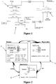
- An illustration of the CCR process for CO 2 capture from combustion flue gas is provided in Figure 1 .
- the sorbent mixture consisting of recycled as well as fresh calcium sorbent is fed to a calciner 1 where it is calcined at 950° C.
- the resultant lime is conveyed to a pressure hydrator 2 where steam and the lime react to produce Ca(OH) 2 .
- the Ca(OH) 2 is dehydrated to form CaO either in a separate dehydration reactor (not shown in Figure 1 ) or in the carbonation reactor 3 where the CaO reacts with the flue gas to form CaCO 3 and CaSO 4 and a CO 2 and SO 2 free gas stream.
- SO 2 may be independently removed prior to CO 2 removal.
- the sorbent from the carbonation reactor is then conveyed back to the calciner 1 and the process is continued.
- pressure hydration of high calcitic limes can improve the thermal efficiency of the calcium looping process by the complete removal of CO 2 during the water gas shift reaction (WGS).
- WGS water gas shift reaction
- the insitu removal of the product CO 2 during the WGS reaction enhances the yield of hydrogen produced.
- pressure hydration is used to convert both dolomitic limestones and high magnesium content ores into hydrates (either Calcium hydrate/magnesium hydrate mixtures or magnesium hydrate).
- the exemplary embodiments use pressure hydration of high calcium content oxides to improve the quality of the heat generated by hydration (for example, at 2068.43 KpA (300 psi), the hydration temperature is 600° C) and lower the energy penalty associated with the sorbent enhanced WGS Reaction .
- FIG. 2 An illustration of the calcium looping process is shown in Figure 2 .
- the Ca(OH) 2 along with the syngas is fed to the carbonation reactor 30 which is operated at 600° C.
- the Ca(OH) 2 decomposes at 600° C to form steam and CaO.
- the steam reacts with the CO in syngas to form CO 2 and H 2 while the CaO captures the CO 2 , sulfur and halide impurities. Since all the steam required for the water gas shift reaction is supplied by the decomposition of Ca(OH) 2 no excess steam needs to be added to the carbonation reactor 30.
- the carbonated sorbent is then regenerated in the calciner 10 to form CaO and a sequestration ready CO 2 stream if operated below the decomposition temperature of CaSO 4 .
- calciner 10 operating temperatures may be lowered with the addition of diluted gas that can be separated from CO 2 , such as steam.
- the heat for the calciner 30 may be provided through indirect-fired, oxyfuel fired with natural gas, coal, or other fossil fuels.
- the regenerated sorbent is then injected into a hydrator 20 where it is converted to Ca(OH) 2 in the presence of steam at high pressures and temperatures.
- the reactivated Ca(OH) 2 sorbent is then reinjected into the carbonation reactor 30 and the cycle is continued.
- the Ohio State University has conducted many experiments showing that atmospheric hydrated high calcium lime is very reactive toward CO 2 removal.
- the WGS reaction approaches nearly 70 to 90% conversion to H 2 at 101.325 kPa (one atmosphere pressure).
- the reactions occurring in the carbonator are: Ca(OH) 2 ⁇ CaO + H 2 O CO + H 2 O ⁇ H 2 + CO 2 CaO + CO 2 ⁇ CaCO 3 CaO + H 2 S ⁇ CaS + H 2 O CaO + COS ⁇ CaS +CO 2 CaO + 2HCl ⁇ CaCl 2 +H 2 O
- the reaction in the hydrator is: CaO + 2 O ⁇ Ca(OH) 2
- the one problem with these two enhanced WGS reaction mechanisms is the energy penalty associated with the hydration or the reactivation step. Atmospheric hydration releases its hydration energy at about 110° C. This is lower than the dehydration temperature of hydrated lime. Additional energy must be used to raise the quality of the heat so that the dehydration reaction can proceed. Pressurized hydration goes forward at temperatures of 600° C and 300 psi pressure. This produces heat with a quality that can be used to dehydrate hydrated lime. For minimal pumping energy, the process saves over 235.58 kcal/mole of useful energy. ASPEN model simulations and experimental results have showed that the hydration reaction goes toward calcium hydrate under these conditions.
- Table 1 Comparison of Pressure and Atmospheric Hydrated Lime Variable Without Hydration Pressure Hydrated Atmospheric Hydrated Percent Hydrated,% - 80% 90% CO 2 Capture Capacity, % 17% 45% 55%
- Figure 3 depicts the design of a pressure hydrator 100 in which the powdered sorbent is pumped into the hydrator 100 which is maintained at high pressure. Steam at high pressure is also fed into the hydrator 100 which has a paddle mixer 50 to promote mixing of the solids with the steam. The hydrated sorbent then exits the hydrator through a lock hopper 60.
- FIG. 4 illustrates an exemplary embodiment of the integration of the CCR process in a conventional coal fired power plant for the production of electricity without carbon emissions.
- fresh limestone make up 101 which ranges from 1 - 5% of the total sorbent in circulation is added to the recycled sorbent stream 103 and fed to the kiln 700.
- the energy for the calcination reaction at >900° C in the kiln 700 is provided by a reheat boiler 720.
- Coal 104 and oxygen 105 are fed into the reheat boiler 720 and the flue gas 106 is sent to the indirectly heated kiln.
- the flue gas 113 from the kiln 700 is then routed to the primary boiler 740.
- the pure CO 2 108 produced in the kiln 700 is cooled and compressed for transportation 110 to the sequestration site.
- the calcined sorbent 107 is cooled down from >900° C to 600° C and fed 109 into the sorbent reactivation reactor 760 shown in more detail in Figure 5 .
- the high quality heat obtained from the reheat boiler 119 and from cooling the solids and the CO 2 is used to generate steam 122 for additional electricity production or to supply the parasitic energy requirement of the process.
- Steam 111 is fed into the sorbent reactivation reactor 760 which is shown in Figure 5 .
- the reactivated calcium oxide sorbent 112 is then fed to the carbonation reactor 780.
- Flue gas generated from burning coal 114 in the primary boiler 740 in addition to the flue gas 113 generated in the reheat boiler 720 is fed to the carbonation reactor 780 where 99% of the CO 2 and SO 2 in the flue gas are removed by the calcium oxide sorbent.
- the exothermic energy 120 produced in the carbonator 780 is used to generate additional electricity.
- the flue gas is separated from the sorbent and emitted into the atmosphere 116. About 1-5% of the sorbent is purged to waste 118 and the rest is recycled back 103 to the kiln 700 and the whole process is repeated.
- FIG 5 depicts an exemplary embodiment of a pressure hydration system 760 which is energy efficient and reduces the parasitic energy requirement of the coal to electricity system.
- pressure hydration unit 902 can be combined with atmospheric dehydration unit 904 to recover the hydration energy.
- the calcium oxide from the calciner 700 is fed into the hydration system 760 along with steam.
- the hydration system consists of two concentric cylindrical reactors 902 and 904.
- the inner reactor 902 is a pressurized vessel where hydration occurs at pressures above 6 bar and at a temperature of 600° C.
- the CaO reacts with the steam to produced calcium hydroxide which is separated from steam and gravity fed to the outer reactor 904.
- the outer concentric reactor 904 is at ambient pressure and the sorbent at 600° C undergoes dehydration to form CaO.
- the exothermic heat generated in the inner concentric reactor 902 from the formation of Ca(OH) 2 is transferred to the outer reactor 904 where it supplies the endothermic energy required for the dehydration reaction.
- the calcium oxide sorbent produced from the hydration-dehydration reactor 760 is then fed into the carbonator 780 along with the flue gas.
- Figure 6 depicts another exemplary embodiment for the integration of the CCR process in a coal fired power plant.
- the Calcium oxide 209 produced in the kiln 700 is fed into the pressure hydrator 800 along with steam 211 to form Ca(OH) 2 .
- the Ca(OH) 2 212 produced in the hydrator 800 is then directly fed into the carbonator 780 where it simultaneously dehydrates and captures the CO 2 and SO 2 from the flue gas.
- the endothermic energy for the dehydration reaction is obtained from the exothermic energy released by the carbonation.
- both the carbonator 780 and the pressure hydrator 800 are exothermic and the high quality (600° C) heat produced 220 and 223 are used to generate additional electricity.
- the pressure hydrator 800 may be a simple fixed, fluidized or moving bed reactor and the need for a separate reactor of dehydration is obviated.
- Figure 7 illustrates another exemplary embodiment for the integration of the CCR process in a coal fired power plant.
- the hydration and dehydration of the sorbent is conducted in two separate reactors 800 and 820 and the heat is transferred from the hydrator 800 to the dehydrator 820 by a working fluid.
- the calcined sorbent 309 from the calciner 700 is fed into the hydration reactor 800 with steam 311 where they are mixed together at a pressure above 6 bar pressure and a temperature of about 600° C. This causes the calcium oxide to hydrate liberating heat which is absorbed by a working fluid.
- the hydrated lime 323 is reduced in pressure to 1 atmosphere and conveyed to the dehydration reactor 820 where the 600° C hydrate begins to dehydrate and the endothermic energy required for the dehydration reaction is provided by the working fluid.
- the CaO sorbent 312 from the dehydrator 820 is then fed into the carbonation reactor 780 for the capture of CO 2 and SO 2 from the flue gas.
- Figure 8 illustrates an exemplary embodiment of heat integration for a coal fired power plant with CO 2 capture using the CCR process.
- Flue gas 405 from the reheat boiler 720 provides the calcination energy and is sent back 408 through the reheat boiler 720 to be heated up further and fed 410 into the primary boiler 740. This is an innovative method of recovering the heat generated in the reheat boiler 720 and producing additional electricity.
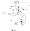
- Figure 9 illustrates an exemplary embodiment of integration of CO 2 removal by the calcium looping process in a traditional gasification system.
- Syngas 505 from the gasifier 840 is fed to the carbonator 780 along with steam 506 from the HRSG and Ca(OH) 2 507 from the hydrator 800.
- the Ca(OH) 2 dehydrates in the carbonator 780 providing steam required for the water gas shift reaction and CaO for the removal of CO 2 , sulfur and halide impurities.
- the insitu removal of CO 2 during the water gas shift reaction improves the yield of hydrogen produced and the product hydrogen stream 510 is cooled down 524 and used as a fuel, to produce electricity, liquid fuels or chemicals.
- a portion of the sorbent stream from the carbonator 780 is purged and a make up of fresh limestone 512 is added before entering the calciner 700.
- the energy for the calcination reaction is provided by combusting coal 517 in a reheat boiler 720 and using the flue gas 518 to heat the calciner 700 indirectly.
- the hot flue gas 514 from the calciner 700 is then cooled down to 600° C in a HRSG 860 and sent 523 to the carbonator 780 where the CaO sorbent reacts with the CO 2 and SO 2 in the gas during hydrogen production.
- the CO 2 514 produced in the calciner 700 is cooled in an HRSG 860 and compressed for transportation and sequestration.
- a small amount of the hydrogen 516 may also be combusted in the calciner 700 to provide heat directly and steam (which is a product of the combustion) which is a carrier gas and aids in reducing the temperature of calcination.
- the calcined CaO sorbent 519 is then reactivated by pressure hydration with steam at about 600° C and a pressure greater than about 6 bars.
- the Ca(OH) 2 507 produced is then fed directly into the carbonator 780.
- the exothermic energy 509 from the carbonation reactor 780, hydrator 800, cooling of the CO 2 , H 2 , flue gas and solids is used to produce additional electricity a part of which is used to supply the parasitic energy requirement of the process.
- the reacted sorbent that exits the carbonation reactor 780 contains calcium carbonate, calcium sulfate and unreacted calcium oxide.
- One method of operation is to send substantially all the reacted sorbent exiting the carbonator 780 to back into the calciner 700, and through the reactivation process.
- a second method of operation exists in which the reacted sorbent exiting the carbonator 780 is split into two streams. The first stream may be sent to the calciner 700 for reactivation while a second stream may be sent directly back into the carbonator 780.
- the two stream approach may aid in reducing the parasitic energy requirement as all the reacted sorbent need not be calcined and recycled every cycle.
- exemplary hydration of the sorbent may either be done every cycle after calcination or once every few cycles depending on the extent of sintering of the sorbent.
- hydration may be conducted at temperatures between about 300° C to about 500° C and about 1 atmosphere. More specifically, between about 350° C and about 512 °C and about 1 atmosphere. Hydration at temperatures above about 300° C is sufficient such that heat generated from exothermic reaction can be extracted to generate steam for a steam turbine or used for heat exchange.
- the reactivity testing of CaO sorbents for carbonation was carried out in a Perkin Elmer thermogravimetric analyzer (TGA-7) apparatus. The balance can measure accurately up to 1 ⁇ g. A small sample of the sorbent (5-20 mg) is placed in a quartz boat. The weight of the sample was recorded every second. Calcination was conducted in the presence of 100% N 2 at 700° C while carbonation was conducted in the presence of 10% CO 2 and 90% N 2 at 650C.
- TGA-7 Perkin Elmer thermogravimetric analyzer
- Figure 11 is an illustration of an integral fixed-bed reactor setup.
- Figure 12 is an illustration of a rotary calciner experimental setup.
- the bench scale experimental setup consists of a fixed bed reactor connected to a continuous gas analysis system and a rotary calciner connected to a CO 2 analyzer. Calcination under realistic conditions was conducted in the rotary calciner at various temperatures ranging from 800° to 1000° C. Different carrier gases such as steam and CO 2 were evaluated and a residence time of 30 minutes was maintained.
- a fixed bed reactor was used to conduct carbonation, pressure hydration and experiments for the production of hydrogen from syngas by the simultaneous water gas shift and carbonation reaction.
- the mixture of gases from the cylinders is regulated and sent into the fixed bed reactor by means of mass flow controllers.
- the mass flow controllers can handle a pressure of about 21 atmospheres.
- From the mass flow controllers the reactant gases flow to the steam generating unit.
- the steam generating unit is maintained at a temperature of 200° C and contains a packing of quartz chips which provide a large surface area of contact between the reactant gases and the water.
- the steam generating unit not only facilitates the complete evaporation on the water being pumped into the steam generating unit but it also serves to preheat the reactant gases entering the reactor.
- the reactor has been provided with a pressure gauge and a thermocouple to monitor the temperature and pressure within.
- the reactant gases leaving the reactor enter the back pressure regulator which builds pressure by regulating the flow rate of the gases.
- the pressure regulator is very sensitive and the pressure within the reactor can be changed quickly without any fluctuations.
- the back pressure regulator is also capable of maintaining a constant pressure for a long period of time thereby increasing the accuracy of the experiments conducted.
- This back pressure regulator is capable of building pressures of up to 68.9 atmospheres (1000 psig).
- the inlet of the backpressure regulator is connected to the reactor rod and the outlet is connected to a heat exchanger.
- the product gas at the exit of the heat exchanger is conditioned in a tower containing a desiccant and is sent to a set of continuous analyzers capable of determining the concentrations of CO, CO 2 , H 2 S, CH4 and H 2 in the gas stream. 5 g of the sorbent is loaded into the reactor and the pressure, temperature and gas flow rates are adjusted for each run.
- the steam free gas compositions at the outlet of the reactor are monitored continuously using the CO, CO 2 , H 2 S, CH4 and H 2 gas analyzer system described above.
- the carrier gas containing a mixture of CO 2 and steam is fed into a rotating reactor containing the solid to be calcined.
- the reactor is enclosed in a furnace and heated to the required temperature which is monitored by means of a thermocouple fixed to the reactor.
- the exit gas is conditioned and fed into a CO 2 analyzer which is used to detect the onset and completion of the calcination reaction.
- Figure 13 is a photo of a sub-pilot plant demonstration of the CCR process for CO 2 and SO 2 capture.
- An underfed stoker combusts approximately 9.07 Kilograms (20 pounds) per hour of stoker-grade coal.
- the generated flue gas stream contains 10%-15% carbon dioxide (CO 2 ) and approximately 5000 ppm of sulfur dioxide (SO 2 ).
- a variable-frequency Induced Draft (ID) fan located at the end of the process, pulls the flue gas stream through the ductwork. A zero-pressure point is maintained in the stoker, where the negative pressure of the ID fan is balanced by the positive pressure of the air blower, which is used as the source of oxygen for coal-combustion.
- the feed rate of the sorbent is set by controlling the revolutions per minute of the screw and obtained through correlations between the feed rate and the revolutions per minute.
- the FEECO rotary calciner is indirectly-heated via electricity and has a variable residence time between 30 minutes and 45 minutes.
- the residence time is controlled by a variable frequency drive that determines the revolutions per minute of the rotary calciner.
- the sorbent while in the calciner, can be preheated to minimize the temperature drop that occurs in the carbonator reactor.
- a double-dump valve which acts as a gas-solid separator, and an exhaust are located at the outlet of the calciner. The double-dump valve allows the pressure in the rotary calciner to be maintained without being affected by the pressure in the flue gas stream, while also allowing the solids to enter the carbonation reactor, where the sorbent contacts the flue gas stream.
- the carbonation reactor contacts the flue gas stream and the solid sorbent in the temperature range between 400° C and 750° C.
- the solid sorbent is injected in the downer of the carbonation reactor and is entrained by the flue gas stream.
- the solid sorbent simultaneously decomposes into calcium oxide (CaO, commercially known as lime) and water (H 2 O) and reacts with both carbon dioxide (CO 2 ) and (SO 2 ) present in the flue gas stream to form calcium carbonate (CaCO 3 , commercially known as limestone) and calcium sulfate (CaSO 4 , commercially known as gypsum).
- the residence time in the entrained bed reactor can be varied between 0.3 seconds and 0.6 seconds.
- a cyclone Following the carbonation reactor is a cyclone.
- the flue gas, and any solids not captured by the cyclone report to a Torit-Donaldson down-flow baghouse, where any captured solids report to a 55-gallon drum and the particulate-free flue gas stream exits to the outside atmosphere.
- the solids captured by the cyclone then enter into the calciner.
- the calciner outlet is disconnected from the carbonation reactor and connected directly to a 55-gallon drum.
- the solids collected in the baghouse are then placed into the Schenck-Accurate hopper.
- the calciner is pre-heated to a maximum temperature of 950 C. Upon completion of heating, the solid from the carbonation reactor are fed into the calciner.
- the limestone decomposes into calcium oxide and carbon dioxide (CO 2 ). Due to the stability of the calcium sulfate, it remains as calcium sulfate in the calciner.
- the pure, dry CO 2 gas exits through the exhaust of the calciner, while the solid mixture, consisting of calcium oxide, calcium carbonate, and calcium sulfate, reports to the 55-gallon drum.
- the collected solids are then hydrated at atmospheric conditions to produce a dry hydrate, which completes the cycle.
- the dry hydrate formed is used as the feed for the next cycle.
- gas analyzers To monitor the gas composition and analyze the percent removal of both carbon dioxide and sulfur dioxide, two sets of gas analyzers are employed. One set of gas analyzers is located upstream of sorbent injection and is used as the baseline. The other set of gas analyzers is located downstream of the sorbent injection. The difference between the two measurements determines the percent removal.
- the gas analyzers are CAI 600 analyzers and continuously monitor the concentrations of CO 2 , SO 2 , and CO.
- a CAI NOxygen analyzer monitors the upstream oxygen and nitrogen oxides concentration
- Teledyne Analytical P100 analyzer monitors the downstream oxygen concentration. All data is continuously recorded to a computer.
- thermocouples continuously measure the temperature throughout the system.
- Several manometers are used to measure the pressure drop and static pressure of the system.
- the CO 2 capture capacity of calcium oxide obtained from calcium hydroxide, PCC and as received ground lime was determined in a thermogravimetric analyzer. In order to improve the strength of the PCC particles, the PCC powder was pelletized into 2mm pellets and then ground to a size of 150 microns. The CO 2 capture capacity of the PCC pellets as well as the pelletized and broken sorbent was also determined. During these test the calcination was conducted under ideal conditions in 100% N 2 at 700° C and the carbonation was conducted in 10% CO 2 at 650° C.
- the CO 2 capture capacity has been defined by the weight % capture which is the grams of CO 2 removed/gram of the CaO sorbent. It can be seen that the weight % capture attained by the sorbent obtained from PCC powder is 74% when compared to that of 60% attained by the calcium hydroxide sorbent and 20% attained by the ground lime sorbent. The CO 2 capture capacity of the pelletized and broken PCC is almost the same (71%) as the PCC powder as shown in Figure 14 . The PCC pellet requires a very large residence time due to mass transfer resistance but reaches the same final CO 2 capture capacity of 71% as that of the PCC pelletized and broken sorbent.
- the effect of realistic calcination conditions in a rotary bed calciner was investigated on the reactivity of the sorbent.
- the CO 2 capture capacity of fresh limestone calcined in N 2 at 700° C is 50 wt%. Calcination in the presence of pure CO 2 at 900° C, decreases the CO 2 capture capacity of the sorbent to 28 wt%.
- calcination in the presence of steam was explored. As shown in Figure 15 the CO 2 capture capacity was found to increase from 28% when calcined in pure CO 2 to 45% in the presence of 50% of steam and 50% CO 2 .
- the effect of the concentration of steam in the carrier gas was also investigated on the CO 2 capture capacity of the sorbent.
- the concentration of steam in the carrier gas With the increase in the concentration of steam in the carrier gas, the sintering of the sorbent is reduced and the CO 2 capture capacity of the sorbent is increased.
- the CO 2 capture capacity of fresh PCC is 60 wt % capture and after the first calcination at 900° C in the presence of steam and CO 2 it decreases to 45%. During the second cycle calcination it further drops to 35% and during the third to 25%.
- This decrease in CO 2 capture capacity can be attributed to the progressive sintering of the solid at high temperatures in the presence of CO 2 and steam. Due to this decrease in CO 2 capture capacity of the sorbent the amount of solids in circulation and make up rate of the sorbent would be high and hence there is a need to develop a method for the complete reactivation of the sorbent.
- a solution for decreasing the parasitic energy consumption is to hydrate the sorbent at a temperature higher than the dehydration temperature so that the exothermic hydration energy can be used to supply energy required for the endothermic dehydration reaction.
- the hydration temperature is between the temperature of calcination and carbonation, cooling and reheating of the solids is avoided.
- the parasitic energy requirement was reduced to 24%.
- the addition of hydration to the over all process does not cause an increase in the parasitic energy requirement.
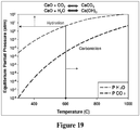
- CaO does not undergo hydration at atmospheric pressure as shown in Figure 19 .
- hydration is conducted at a pressure of 6 bar and higher to completely hydrate the sorbent.
- the sorbent reactivity is completely restored and the process efficiency is increased.
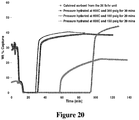
- Figure 20 shows the effect of pressure hydration at 600° C for pressures ranging from 790.80 kPa (100 psig) to 2169.75 kPa (300 psig). It was found that the reactivity of the sorbent increases from 18% to 45% by pressure hydration at 600° C and 100 psig. The reactivity of the sorbent was found to increase with the decrease in pressure although the extent of hydration remained the same at all pressures.
- Figure 21 shows the effect of Calcium:Carbon mol ratio on carbon dioxide removal for multiple sorbents on a once-through basis.
- Commercial-grade calcium hydroxide clearly outperforms the commercial-grade lime in removing carbon dioxide from a coal-combustion flue gas stream. At a calcium:carbon mol ratio of approximately 1.7, virtually all CO 2 can be removed using calcium hydroxide.
- Figure 22 shows the percent of CO 2 removed from a coal-combustion flue gas stream for calcium hydroxide and provides a logarithmic relationship between the CO 2 removed and the calcium:carbon mol ratio with a high-degree of correlation. Approximately 1.5:1 Calcium:Carbon mol ratio would be required for complete CO 2 removal, according to the regression equation.
- Figure 23 shows the removal of sulfur dioxide from the flue gas stream for multiple sorbents and calcium:carbon ratios.
- the SO 2 removal is independent of the calcium:carbon mol ratio due to calcium hydroxide's high degree of reactivity.
- the sulfur content of coal is significantly lower than the carbon content of coal, the calcium:sulfur ratio will always be greater.
- a coal has 75% carbon and 5% sulfur, a 1:1 calcium:carbon mol ratio would be equivalent to a 40:1 calcium:sulfur ratio. This allows even the commercial-grade lime, which had poor CO 2 removals, to remove sulfur dioxide to a high degree at modest calcium:carbon ratios.
- Figure 23 is obtained for single-cycle studies; however, complete SO 2 removal has been obtained for multiple cycles.
- Figure 25 shows the results from the cyclic studies.
- the calcium:carbon mol ratio was kept constant, with a value around 0.65.
- the calcium hydroxide sorbent with hydration during every cycle maintained its reactivity over the course of 4 cycles, with no indication of loss of reactivity. This shows that hydration completely reactivates the sorbent and reverses the effect of sintering.
- the initial sorbent in the first cycle was calcium hydroxide.
- the calcium hydroxide was not regenerated, and the calcium carbonate formed in the carbonation reaction was calcined to form calcium oxide. The calcium oxide was then carbonated, and the cycle repeated.
- carbon dioxide capture decreases dramatically.
- Figure 26 shows the reactivity of the sorbent for multicyclic CO 2 capture with hydration for which the % CO 2 removal is illustrated in Figure25 .
- Calcination in the subpilot plant kiln reduces the CO 2 capture capacity of the sorbent from 55% (12.5 moles/Kg CaO) to 20% (4.54 moles/Kg CaO).
- the subsequent hydration of the sorbent at the Carmeuse Limestone company facility resulted in the increase in the capture capacity of the sorbent back to 55% (12.5 moles/Kg CaO).
- Three cycles of carbonation and calcination at OSU and hydration at Carmeuse Limestone Company have been conducted and the CO 2 capture capacity has remained constant at 55% (12.5 moles/Kg CaO).
- the regenerability of the sorbent due to hydration has been validated at the lab, bench and sub-pilot scale.
Landscapes
- Chemical & Material Sciences (AREA)
- Chemical Kinetics & Catalysis (AREA)
- Analytical Chemistry (AREA)
- Organic Chemistry (AREA)
- Engineering & Computer Science (AREA)
- General Chemical & Material Sciences (AREA)
- Oil, Petroleum & Natural Gas (AREA)
- Health & Medical Sciences (AREA)
- Inorganic Chemistry (AREA)
- Biomedical Technology (AREA)
- Environmental & Geological Engineering (AREA)
- Life Sciences & Earth Sciences (AREA)
- Geology (AREA)
- Physics & Mathematics (AREA)
- Thermal Sciences (AREA)
- Sustainable Development (AREA)
- Treating Waste Gases (AREA)
- Solid-Sorbent Or Filter-Aiding Compositions (AREA)
- Gas Separation By Absorption (AREA)
Applications Claiming Priority (2)
| Application Number | Priority Date | Filing Date | Title |
|---|---|---|---|
| US11617208P | 2008-11-19 | 2008-11-19 | |
| PCT/US2009/065224 WO2010059882A2 (en) | 2008-11-19 | 2009-11-19 | Carbonation calcination reaction process for co2 capture using a highly regenerable sorbent |
Publications (3)
| Publication Number | Publication Date |
|---|---|
| EP2385873A2 EP2385873A2 (en) | 2011-11-16 |
| EP2385873A4 EP2385873A4 (en) | 2012-06-20 |
| EP2385873B1 true EP2385873B1 (en) | 2018-05-16 |
Family
ID=42198813
Family Applications (1)
| Application Number | Title | Priority Date | Filing Date |
|---|---|---|---|
| EP09828257.7A Active EP2385873B1 (en) | 2008-11-19 | 2009-11-19 | Carbonation calcination reaction process for co2 capture using a highly regenerable sorbent |
Country Status (6)
| Country | Link |
|---|---|
| US (1) | US8512661B2 (es) |
| EP (1) | EP2385873B1 (es) |
| CN (1) | CN102307646B (es) |
| CA (1) | CA2743911C (es) |
| ES (1) | ES2684133T3 (es) |
| WO (1) | WO2010059882A2 (es) |
Families Citing this family (37)
| Publication number | Priority date | Publication date | Assignee | Title |
|---|---|---|---|---|
| US7618606B2 (en) | 2003-02-06 | 2009-11-17 | The Ohio State University | Separation of carbon dioxide (CO2) from gas mixtures |
| WO2008039783A2 (en) | 2006-09-25 | 2008-04-03 | The Ohio State University | Calcium looping process for high purity hydrogen production |
| US8496909B2 (en) | 2008-10-13 | 2013-07-30 | The Ohio State University Research Foundation | Calcium looping process for high purity hydrogen production integrated with capture of carbon dioxide, sulfur and halides |
| CN103249816B (zh) * | 2010-12-24 | 2016-05-18 | 株式会社Ihi | 生成气体的重整方法和装置 |
| RU2482559C2 (ru) * | 2011-03-15 | 2013-05-20 | Общество с ограниченной ответственностью "ИНТОВ" (ООО "ИНТОВ") | Способ и установка для получения радона |
| WO2012142084A1 (en) | 2011-04-11 | 2012-10-18 | ADA-ES, Inc. | Fluidized bed method and system for gas component capture |
| ES2401294B1 (es) * | 2011-06-24 | 2014-05-09 | Consejo Superior De Investigaciones Científicas (Csic) | DISPOSITIVO Y PROCEDIMIENTO PARA LA CAPTURA DE CO2 POR CARBONATACION DE CaO |
| CN104812467B (zh) * | 2012-09-20 | 2017-05-17 | Ada-Es股份有限公司 | 用于恢复被热稳定盐污染的吸附剂上的功能位置的方法和系统 |
| EP2722096B1 (en) * | 2012-10-16 | 2016-08-24 | General Electric Technology GmbH | Desulfurization in a regenerative calcium cycle system |
| EP2722094B1 (en) * | 2012-10-17 | 2020-06-17 | General Electric Technology GmbH | Capturing of co2 from a process gas |
| CN102921292B (zh) * | 2012-11-13 | 2014-08-27 | 山东大学 | 提高造纸白泥在燃煤流化床锅炉系统中捕集co2性能的方法 |
| US9481837B2 (en) | 2013-03-15 | 2016-11-01 | The Babcock & Wilcox Company | Chemical looping processes for partial oxidation of carbonaceous fuels |
| US20160158697A1 (en) * | 2013-07-11 | 2016-06-09 | Newcastle Innovation Limited | Mineral Carbonate Looping Reactor for Ventilation Air Methane Mitigation |
| US8877150B1 (en) * | 2013-07-26 | 2014-11-04 | The Ohio State University | Single-step process for the simultaneous removal of CO2, SOx and NOx from a gas mixture |
| US9810146B2 (en) | 2014-07-17 | 2017-11-07 | Saudi Arabian Oil Company | Calcium sulfate looping cycles for sour gas combustion and electricity production |
| TWI499449B (zh) * | 2014-10-27 | 2015-09-11 | Ind Tech Res Inst | 二氧化碳捕獲裝置與方法 |
| PT108290B (pt) * | 2015-03-17 | 2018-12-10 | Secil Companhia Geral De Cal E Cimento S A | Método de produção de um clinquer de baixo teor de carbono |
| ES2595443B1 (es) * | 2015-06-29 | 2017-11-07 | Universidad De Sevilla | Sistema integrado de calcinación-carbonatación y ciclo de lazo cerrado de CO2 para almacenamiento de energía termoquímica y generación de energía eléctrica |
| CN105944528B (zh) * | 2016-05-13 | 2018-12-14 | 东南大学 | 一种利用Ca/Cu基复合颗粒捕集烟气中CO2的装置及方法 |
| GB2560347B (en) | 2017-03-08 | 2021-11-17 | Fjell Biodry As | Gas capture system |
| CN106975341A (zh) * | 2017-04-28 | 2017-07-25 | 安徽建筑大学 | 一种带蒸汽活化反应器的钙基吸收剂循环脱除二氧化碳的装置及其方法 |
| CN107694340A (zh) * | 2017-04-28 | 2018-02-16 | 安徽建筑大学 | 一种钙基吸收剂活性再生及循环脱除co2的方法 |
| US10213730B1 (en) | 2017-08-22 | 2019-02-26 | Saudi Arabian Oil Company | Process for acid gas treatment and power generation |
| CN107983112B (zh) * | 2017-11-29 | 2021-06-18 | 安徽建筑大学 | 一种带填料活化再生的回转式固定床二氧化碳循环捕获方法 |
| CN108619896B (zh) * | 2018-05-16 | 2023-11-21 | 安徽建筑大学 | 一种基于切换式填充床反应器的co2循环脱除装置及方法 |
| CN109507360B (zh) * | 2018-11-14 | 2020-05-22 | 西安交通大学 | 一种热载气温度震荡条件下碳酸盐高温煅烧反应特性的实验装置及测试方法 |
| CN112441890A (zh) * | 2020-11-25 | 2021-03-05 | 武汉理工大学 | 一种垃圾气化制二甲醚的方法及系统 |
| US11913362B2 (en) | 2020-11-30 | 2024-02-27 | Rondo Energy, Inc. | Thermal energy storage system coupled with steam cracking system |
| US11913361B2 (en) * | 2020-11-30 | 2024-02-27 | Rondo Energy, Inc. | Energy storage system and alumina calcination applications |
| IL303311A (en) | 2020-11-30 | 2023-07-01 | Rondo Energy Inc | Energy storage system and applications |
| EP4015063A1 (en) | 2020-12-17 | 2022-06-22 | Consejo Superior De Investigaciones Científicas (CSIC) | Method to capture co2 in flue gases emitted intermittently |
| CN113663636B (zh) * | 2021-08-31 | 2022-10-14 | 南京工业大学 | 一种回转式钙基高温热化学储能反应装置及储能反应方法 |
| EP4205832A1 (en) | 2021-12-29 | 2023-07-05 | Consejo Superior de Investigaciones Científicas (CSIC) | Method to increase co2 capture efficiencies by carbonation and related carbonator |
| WO2023140985A1 (en) * | 2022-01-18 | 2023-07-27 | Carbon Capture Enterprises Llc | Carbon capture via kiln |
| CN114522533B (zh) * | 2022-03-07 | 2023-07-25 | 哈尔滨锅炉厂有限责任公司 | 钙基热载体循环烟气二氧化碳捕集系统及方法 |
| CN114768501B (zh) * | 2022-04-22 | 2024-04-30 | 瀜矿环保科技(上海)有限公司 | 烟气中二氧化碳捕集与基于工业固废的二氧化碳矿化耦合系统 |
| CN117074602A (zh) * | 2023-08-29 | 2023-11-17 | 湛江电力有限公司 | 多因素下钙基热化学储能材料的样品制取系统与方法 |
Family Cites Families (15)
| Publication number | Priority date | Publication date | Assignee | Title |
|---|---|---|---|---|
| US3847563A (en) * | 1973-05-02 | 1974-11-12 | Westinghouse Electric Corp | Multi-stage fluidized bed coal gasification apparatus and process |
| US4312280A (en) * | 1980-03-13 | 1982-01-26 | The United States Of America As Represented By The United States Department Of Energy | Method of increasing the sulfation capacity of alkaline earth sorbents |
| US4400181A (en) * | 1982-01-28 | 1983-08-23 | Hydrocarbon Research, Inc. | Method for using fast fluidized bed dry bottom coal gasification |
| IN188644B (es) * | 1995-08-21 | 2002-10-26 | Abb Research Ltd | |
| JP3248514B2 (ja) * | 1998-10-29 | 2002-01-21 | 日本鋼管株式会社 | 排出炭酸ガスの削減方法 |
| US6569388B1 (en) * | 1999-07-28 | 2003-05-27 | The Ohio State University Research Foundation | Carbonation ash reactivation process and system for combined SOx and NOx removal |
| DE10045586C2 (de) * | 2000-09-15 | 2002-07-18 | Alstom Power Boiler Gmbh | Verfahren sowie Einrichtung zur Reinigung von Schwefeldioxid enthaltenden Rauchgasen |
| US7067456B2 (en) * | 2003-02-06 | 2006-06-27 | The Ohio State University | Sorbent for separation of carbon dioxide (CO2) from gas mixtures |
| US7618606B2 (en) * | 2003-02-06 | 2009-11-17 | The Ohio State University | Separation of carbon dioxide (CO2) from gas mixtures |
| CA2543990A1 (en) * | 2003-11-14 | 2005-05-26 | Her Majesty The Queen In Right Of Canada As Represented By The Ministeof Natural Resources | Pre-treatment of lime-based sorbents using hydration |
| JP2005239954A (ja) * | 2004-02-27 | 2005-09-08 | Mitsubishi Materials Corp | 水素を含む高カロリーガス生成装置及び生成方法 |
| WO2006113673A2 (en) * | 2005-04-18 | 2006-10-26 | The Trustees Of Columbia University In The City Of New York | Methods and systems for reducing emissions |
| WO2007045048A1 (en) * | 2005-10-21 | 2007-04-26 | Calix Pty Ltd | System and method for calcination/carbonation cycle processing |
| EP2004319B8 (en) * | 2006-03-31 | 2015-07-22 | Calix Ltd | System and method for the calcination of minerals |
| WO2009148334A1 (en) * | 2008-06-05 | 2009-12-10 | Industrial Research Limited | Gas separation process |
-
2009
- 2009-11-19 EP EP09828257.7A patent/EP2385873B1/en active Active
- 2009-11-19 CA CA2743911A patent/CA2743911C/en active Active
- 2009-11-19 WO PCT/US2009/065224 patent/WO2010059882A2/en active Application Filing
- 2009-11-19 ES ES09828257.7T patent/ES2684133T3/es active Active
- 2009-11-19 CN CN200980154994.XA patent/CN102307646B/zh active Active
-
2011
- 2011-05-19 US US13/111,794 patent/US8512661B2/en active Active
Non-Patent Citations (1)
| Title |
|---|
| None * |
Also Published As
| Publication number | Publication date |
|---|---|
| US20110286902A1 (en) | 2011-11-24 |
| CA2743911A1 (en) | 2010-05-27 |
| WO2010059882A3 (en) | 2010-08-26 |
| WO2010059882A2 (en) | 2010-05-27 |
| CN102307646B (zh) | 2014-08-27 |
| CA2743911C (en) | 2016-01-12 |
| ES2684133T3 (es) | 2018-10-01 |
| US8512661B2 (en) | 2013-08-20 |
| EP2385873A4 (en) | 2012-06-20 |
| EP2385873A2 (en) | 2011-11-16 |
| CN102307646A (zh) | 2012-01-04 |
Similar Documents
| Publication | Publication Date | Title |
|---|---|---|
| EP2385873B1 (en) | Carbonation calcination reaction process for co2 capture using a highly regenerable sorbent | |
| CA2479886C (en) | Combustion method with integrated carbon dioxide separation by means of carbonation | |
| CA2773080C (en) | Method of capturing co2 by means of cao and the exothermic reduction of a solid | |
| US8496909B2 (en) | Calcium looping process for high purity hydrogen production integrated with capture of carbon dioxide, sulfur and halides | |
| KR20220005074A (ko) | 탄소 포집을 위한 시스템 및 방법 | |
| US9651252B2 (en) | System for CO2 capture from a combustion flue gas using a CaO/CaCO3 chemical loop | |
| Champagne et al. | The effect of steam addition to the calciner in a calcium looping pilot plant | |
| Romano et al. | The Calcium looping process for low CO2 emission cement plants | |
| MX2008012528A (es) | Procedimiento de precalcinacion con produccion de co2 puro o facilmente purificable proveniente de la descomposicion de carbonatos. | |
| CN106975341A (zh) | 一种带蒸汽活化反应器的钙基吸收剂循环脱除二氧化碳的装置及其方法 | |
| CN103249816A (zh) | 生成气体的重整方法和装置 | |
| Fernández et al. | Novel process for hydrogen production through the sorption enhanced reforming of methane combined with chemical looping combustion | |
| Gallucci et al. | A review on recent patents on chemical and calcium looping processes | |
| Hornberger et al. | Demonstration of Calcium Looping Co2 Capture for Cement Plants at Semi Industrial Scale | |
| US20230227354A1 (en) | Method for utilizing co2 in exhaust gas from cement production, and co2 utilizing system | |
| Mahinpey et al. | Application of calcium looping (CaL) technology for CO2 capture | |
| EP3839015B1 (en) | Method of processing exhaust gas | |
| Arias Rozada et al. | Advanced CO2 capture systems based on Calcium Looping for deep decarbonization of flue gases | |
| Arias et al. | Advanced CO2 Capture Systems Based on Calcium Looping for Deep Decarbonization of Flue Gases | |
| Chou et al. | Calcium Looping Carbon Capture Process | |
| CZ31287U1 (cs) | Nízkoemisní energetický systém tvořený integrovaným paroplynovým cyklem s precombustion záchytem CO2 | |
| WO2023140985A1 (en) | Carbon capture via kiln | |
| Romano et al. | CO2 Capture from Industrial Sources by High-temperature Sorbents | |
| CN116583705A (zh) | 水泥熟料制造系统和水泥熟料制造方法 | |
| Senthoorselvan et al. | Cyclic Carbonation and Calcination Studies of Limestone and Dolomite for CO2 Separation From Combustion Flue Gases |
Legal Events
| Date | Code | Title | Description |
|---|---|---|---|
| PUAI | Public reference made under article 153(3) epc to a published international application that has entered the european phase |
Free format text: ORIGINAL CODE: 0009012 |
|
| 17P | Request for examination filed |
Effective date: 20110620 |
|
| AK | Designated contracting states |
Kind code of ref document: A2 Designated state(s): AT BE BG CH CY CZ DE DK EE ES FI FR GB GR HR HU IE IS IT LI LT LU LV MC MK MT NL NO PL PT RO SE SI SK SM TR |
|
| DAX | Request for extension of the european patent (deleted) | ||
| REG | Reference to a national code |
Ref country code: DE Ref legal event code: R079 Ref document number: 602009052369 Country of ref document: DE Free format text: PREVIOUS MAIN CLASS: B01D0053140000 Ipc: B01D0053620000 |
|
| A4 | Supplementary search report drawn up and despatched |
Effective date: 20120521 |
|
| RIC1 | Information provided on ipc code assigned before grant |
Ipc: B01D 53/62 20060101AFI20120514BHEP Ipc: B01D 53/96 20060101ALI20120514BHEP Ipc: B01J 20/34 20060101ALI20120514BHEP |
|
| STAA | Information on the status of an ep patent application or granted ep patent |
Free format text: STATUS: EXAMINATION IS IN PROGRESS |
|
| 17Q | First examination report despatched |
Effective date: 20170207 |
|
| GRAP | Despatch of communication of intention to grant a patent |
Free format text: ORIGINAL CODE: EPIDOSNIGR1 |
|
| STAA | Information on the status of an ep patent application or granted ep patent |
Free format text: STATUS: GRANT OF PATENT IS INTENDED |
|
| INTG | Intention to grant announced |
Effective date: 20171130 |
|
| GRAS | Grant fee paid |
Free format text: ORIGINAL CODE: EPIDOSNIGR3 |
|
| GRAA | (expected) grant |
Free format text: ORIGINAL CODE: 0009210 |
|
| STAA | Information on the status of an ep patent application or granted ep patent |
Free format text: STATUS: THE PATENT HAS BEEN GRANTED |
|
| AK | Designated contracting states |
Kind code of ref document: B1 Designated state(s): AT BE BG CH CY CZ DE DK EE ES FI FR GB GR HR HU IE IS IT LI LT LU LV MC MK MT NL NO PL PT RO SE SI SK SM TR |
|
| REG | Reference to a national code |
Ref country code: GB Ref legal event code: FG4D |
|
| REG | Reference to a national code |
Ref country code: CH Ref legal event code: EP |
|
| REG | Reference to a national code |
Ref country code: IE Ref legal event code: FG4D |
|
| REG | Reference to a national code |
Ref country code: DE Ref legal event code: R096 Ref document number: 602009052369 Country of ref document: DE |
|
| REG | Reference to a national code |
Ref country code: AT Ref legal event code: REF Ref document number: 999018 Country of ref document: AT Kind code of ref document: T Effective date: 20180615 |
|
| RAP2 | Party data changed (patent owner data changed or rights of a patent transferred) |
Owner name: OHIO STATE INNOVATION FOUNDATION |
|
| REG | Reference to a national code |
Ref country code: NL Ref legal event code: MP Effective date: 20180516 |
|
| REG | Reference to a national code |
Ref country code: DE Ref legal event code: R082 Ref document number: 602009052369 Country of ref document: DE Representative=s name: WALLINGER RICKER SCHLOTTER TOSTMANN PATENT- UN, DE Ref country code: DE Ref legal event code: R081 Ref document number: 602009052369 Country of ref document: DE Owner name: OHIO STATE INNOVATION FOUNDATION, COLUMBUS, US Free format text: FORMER OWNER: THE OHIO STATE UNIVERSITY RESEARCH FOUNDATION, COLUMBUS, OHIO, US |
|
| REG | Reference to a national code |
Ref country code: ES Ref legal event code: FG2A Ref document number: 2684133 Country of ref document: ES Kind code of ref document: T3 Effective date: 20181001 |
|
| REG | Reference to a national code |
Ref country code: LT Ref legal event code: MG4D |
|
| PG25 | Lapsed in a contracting state [announced via postgrant information from national office to epo] |
Ref country code: LT Free format text: LAPSE BECAUSE OF FAILURE TO SUBMIT A TRANSLATION OF THE DESCRIPTION OR TO PAY THE FEE WITHIN THE PRESCRIBED TIME-LIMIT Effective date: 20180516 Ref country code: FI Free format text: LAPSE BECAUSE OF FAILURE TO SUBMIT A TRANSLATION OF THE DESCRIPTION OR TO PAY THE FEE WITHIN THE PRESCRIBED TIME-LIMIT Effective date: 20180516 Ref country code: BG Free format text: LAPSE BECAUSE OF FAILURE TO SUBMIT A TRANSLATION OF THE DESCRIPTION OR TO PAY THE FEE WITHIN THE PRESCRIBED TIME-LIMIT Effective date: 20180816 Ref country code: SE Free format text: LAPSE BECAUSE OF FAILURE TO SUBMIT A TRANSLATION OF THE DESCRIPTION OR TO PAY THE FEE WITHIN THE PRESCRIBED TIME-LIMIT Effective date: 20180516 Ref country code: NO Free format text: LAPSE BECAUSE OF FAILURE TO SUBMIT A TRANSLATION OF THE DESCRIPTION OR TO PAY THE FEE WITHIN THE PRESCRIBED TIME-LIMIT Effective date: 20180816 |
|
| PG25 | Lapsed in a contracting state [announced via postgrant information from national office to epo] |
Ref country code: GR Free format text: LAPSE BECAUSE OF FAILURE TO SUBMIT A TRANSLATION OF THE DESCRIPTION OR TO PAY THE FEE WITHIN THE PRESCRIBED TIME-LIMIT Effective date: 20180817 Ref country code: LV Free format text: LAPSE BECAUSE OF FAILURE TO SUBMIT A TRANSLATION OF THE DESCRIPTION OR TO PAY THE FEE WITHIN THE PRESCRIBED TIME-LIMIT Effective date: 20180516 Ref country code: NL Free format text: LAPSE BECAUSE OF FAILURE TO SUBMIT A TRANSLATION OF THE DESCRIPTION OR TO PAY THE FEE WITHIN THE PRESCRIBED TIME-LIMIT Effective date: 20180516 Ref country code: HR Free format text: LAPSE BECAUSE OF FAILURE TO SUBMIT A TRANSLATION OF THE DESCRIPTION OR TO PAY THE FEE WITHIN THE PRESCRIBED TIME-LIMIT Effective date: 20180516 |
|
| REG | Reference to a national code |
Ref country code: AT Ref legal event code: MK05 Ref document number: 999018 Country of ref document: AT Kind code of ref document: T Effective date: 20180516 |
|
| PG25 | Lapsed in a contracting state [announced via postgrant information from national office to epo] |
Ref country code: CZ Free format text: LAPSE BECAUSE OF FAILURE TO SUBMIT A TRANSLATION OF THE DESCRIPTION OR TO PAY THE FEE WITHIN THE PRESCRIBED TIME-LIMIT Effective date: 20180516 Ref country code: RO Free format text: LAPSE BECAUSE OF FAILURE TO SUBMIT A TRANSLATION OF THE DESCRIPTION OR TO PAY THE FEE WITHIN THE PRESCRIBED TIME-LIMIT Effective date: 20180516 Ref country code: SK Free format text: LAPSE BECAUSE OF FAILURE TO SUBMIT A TRANSLATION OF THE DESCRIPTION OR TO PAY THE FEE WITHIN THE PRESCRIBED TIME-LIMIT Effective date: 20180516 Ref country code: PL Free format text: LAPSE BECAUSE OF FAILURE TO SUBMIT A TRANSLATION OF THE DESCRIPTION OR TO PAY THE FEE WITHIN THE PRESCRIBED TIME-LIMIT Effective date: 20180516 Ref country code: EE Free format text: LAPSE BECAUSE OF FAILURE TO SUBMIT A TRANSLATION OF THE DESCRIPTION OR TO PAY THE FEE WITHIN THE PRESCRIBED TIME-LIMIT Effective date: 20180516 Ref country code: DK Free format text: LAPSE BECAUSE OF FAILURE TO SUBMIT A TRANSLATION OF THE DESCRIPTION OR TO PAY THE FEE WITHIN THE PRESCRIBED TIME-LIMIT Effective date: 20180516 Ref country code: AT Free format text: LAPSE BECAUSE OF FAILURE TO SUBMIT A TRANSLATION OF THE DESCRIPTION OR TO PAY THE FEE WITHIN THE PRESCRIBED TIME-LIMIT Effective date: 20180516 |
|
| REG | Reference to a national code |
Ref country code: DE Ref legal event code: R097 Ref document number: 602009052369 Country of ref document: DE |
|
| PG25 | Lapsed in a contracting state [announced via postgrant information from national office to epo] |
Ref country code: SM Free format text: LAPSE BECAUSE OF FAILURE TO SUBMIT A TRANSLATION OF THE DESCRIPTION OR TO PAY THE FEE WITHIN THE PRESCRIBED TIME-LIMIT Effective date: 20180516 |
|
| PLBE | No opposition filed within time limit |
Free format text: ORIGINAL CODE: 0009261 |
|
| STAA | Information on the status of an ep patent application or granted ep patent |
Free format text: STATUS: NO OPPOSITION FILED WITHIN TIME LIMIT |
|
| 26N | No opposition filed |
Effective date: 20190219 |
|
| PG25 | Lapsed in a contracting state [announced via postgrant information from national office to epo] |
Ref country code: SI Free format text: LAPSE BECAUSE OF FAILURE TO SUBMIT A TRANSLATION OF THE DESCRIPTION OR TO PAY THE FEE WITHIN THE PRESCRIBED TIME-LIMIT Effective date: 20180516 |
|
| REG | Reference to a national code |
Ref country code: CH Ref legal event code: PL |
|
| GBPC | Gb: european patent ceased through non-payment of renewal fee |
Effective date: 20181119 |
|
| PG25 | Lapsed in a contracting state [announced via postgrant information from national office to epo] |
Ref country code: MC Free format text: LAPSE BECAUSE OF FAILURE TO SUBMIT A TRANSLATION OF THE DESCRIPTION OR TO PAY THE FEE WITHIN THE PRESCRIBED TIME-LIMIT Effective date: 20180516 Ref country code: LU Free format text: LAPSE BECAUSE OF NON-PAYMENT OF DUE FEES Effective date: 20181119 |
|
| REG | Reference to a national code |
Ref country code: BE Ref legal event code: MM Effective date: 20181130 |
|
| REG | Reference to a national code |
Ref country code: IE Ref legal event code: MM4A |
|
| PG25 | Lapsed in a contracting state [announced via postgrant information from national office to epo] |
Ref country code: LI Free format text: LAPSE BECAUSE OF NON-PAYMENT OF DUE FEES Effective date: 20181130 Ref country code: CH Free format text: LAPSE BECAUSE OF NON-PAYMENT OF DUE FEES Effective date: 20181130 |
|
| PG25 | Lapsed in a contracting state [announced via postgrant information from national office to epo] |
Ref country code: IE Free format text: LAPSE BECAUSE OF NON-PAYMENT OF DUE FEES Effective date: 20181119 |
|
| PG25 | Lapsed in a contracting state [announced via postgrant information from national office to epo] |
Ref country code: BE Free format text: LAPSE BECAUSE OF NON-PAYMENT OF DUE FEES Effective date: 20181130 |
|
| PG25 | Lapsed in a contracting state [announced via postgrant information from national office to epo] |
Ref country code: GB Free format text: LAPSE BECAUSE OF NON-PAYMENT OF DUE FEES Effective date: 20181119 |
|
| PG25 | Lapsed in a contracting state [announced via postgrant information from national office to epo] |
Ref country code: MT Free format text: LAPSE BECAUSE OF NON-PAYMENT OF DUE FEES Effective date: 20181119 |
|
| PG25 | Lapsed in a contracting state [announced via postgrant information from national office to epo] |
Ref country code: TR Free format text: LAPSE BECAUSE OF FAILURE TO SUBMIT A TRANSLATION OF THE DESCRIPTION OR TO PAY THE FEE WITHIN THE PRESCRIBED TIME-LIMIT Effective date: 20180516 |
|
| PG25 | Lapsed in a contracting state [announced via postgrant information from national office to epo] |
Ref country code: PT Free format text: LAPSE BECAUSE OF FAILURE TO SUBMIT A TRANSLATION OF THE DESCRIPTION OR TO PAY THE FEE WITHIN THE PRESCRIBED TIME-LIMIT Effective date: 20180516 |
|
| PG25 | Lapsed in a contracting state [announced via postgrant information from national office to epo] |
Ref country code: HU Free format text: LAPSE BECAUSE OF FAILURE TO SUBMIT A TRANSLATION OF THE DESCRIPTION OR TO PAY THE FEE WITHIN THE PRESCRIBED TIME-LIMIT; INVALID AB INITIO Effective date: 20091119 Ref country code: MK Free format text: LAPSE BECAUSE OF NON-PAYMENT OF DUE FEES Effective date: 20180516 Ref country code: CY Free format text: LAPSE BECAUSE OF FAILURE TO SUBMIT A TRANSLATION OF THE DESCRIPTION OR TO PAY THE FEE WITHIN THE PRESCRIBED TIME-LIMIT Effective date: 20180516 |
|
| PG25 | Lapsed in a contracting state [announced via postgrant information from national office to epo] |
Ref country code: IS Free format text: LAPSE BECAUSE OF FAILURE TO SUBMIT A TRANSLATION OF THE DESCRIPTION OR TO PAY THE FEE WITHIN THE PRESCRIBED TIME-LIMIT Effective date: 20180916 |
|
| PGFP | Annual fee paid to national office [announced via postgrant information from national office to epo] |
Ref country code: IT Payment date: 20221123 Year of fee payment: 14 Ref country code: FR Payment date: 20221123 Year of fee payment: 14 Ref country code: ES Payment date: 20221201 Year of fee payment: 14 Ref country code: DE Payment date: 20221125 Year of fee payment: 14 |
|
| P01 | Opt-out of the competence of the unified patent court (upc) registered |
Effective date: 20230530 |