EP2385683A2 - Formanordnung - Google Patents
Formanordnung Download PDFInfo
- Publication number
- EP2385683A2 EP2385683A2 EP20100187928 EP10187928A EP2385683A2 EP 2385683 A2 EP2385683 A2 EP 2385683A2 EP 20100187928 EP20100187928 EP 20100187928 EP 10187928 A EP10187928 A EP 10187928A EP 2385683 A2 EP2385683 A2 EP 2385683A2
- Authority
- EP
- European Patent Office
- Prior art keywords
- side portion
- piece
- cross
- outer piece
- assembly
- Prior art date
- Legal status (The legal status is an assumption and is not a legal conclusion. Google has not performed a legal analysis and makes no representation as to the accuracy of the status listed.)
- Withdrawn
Links
- 239000000463 material Substances 0.000 claims abstract description 31
- 238000000034 method Methods 0.000 claims description 14
- 238000005452 bending Methods 0.000 claims 1
- 238000010295 mobile communication Methods 0.000 description 28
- 238000005516 engineering process Methods 0.000 description 23
- 238000000465 moulding Methods 0.000 description 10
- 238000004519 manufacturing process Methods 0.000 description 9
- 238000001746 injection moulding Methods 0.000 description 8
- 238000013459 approach Methods 0.000 description 5
- 238000013461 design Methods 0.000 description 3
- 239000012530 fluid Substances 0.000 description 3
- 239000002245 particle Substances 0.000 description 3
- 229920001169 thermoplastic Polymers 0.000 description 3
- 229920001187 thermosetting polymer Polymers 0.000 description 3
- 239000004416 thermosoftening plastic Substances 0.000 description 3
- 239000004433 Thermoplastic polyurethane Substances 0.000 description 2
- 238000012986 modification Methods 0.000 description 2
- 230000004048 modification Effects 0.000 description 2
- 239000004033 plastic Substances 0.000 description 2
- 229920003023 plastic Polymers 0.000 description 2
- 239000004417 polycarbonate Substances 0.000 description 2
- 229920000515 polycarbonate Polymers 0.000 description 2
- 229920002725 thermoplastic elastomer Polymers 0.000 description 2
- 229920002803 thermoplastic polyurethane Polymers 0.000 description 2
- 239000004593 Epoxy Substances 0.000 description 1
- 239000004677 Nylon Substances 0.000 description 1
- 239000004698 Polyethylene Substances 0.000 description 1
- 239000004793 Polystyrene Substances 0.000 description 1
- 229910000831 Steel Inorganic materials 0.000 description 1
- 239000000956 alloy Substances 0.000 description 1
- 229910045601 alloy Inorganic materials 0.000 description 1
- 239000004411 aluminium Substances 0.000 description 1
- 229910052782 aluminium Inorganic materials 0.000 description 1
- XAGFODPZIPBFFR-UHFFFAOYSA-N aluminium Chemical compound [Al] XAGFODPZIPBFFR-UHFFFAOYSA-N 0.000 description 1
- 238000000429 assembly Methods 0.000 description 1
- 230000000712 assembly Effects 0.000 description 1
- 210000001520 comb Anatomy 0.000 description 1
- 229920000891 common polymer Polymers 0.000 description 1
- 238000010276 construction Methods 0.000 description 1
- 230000000994 depressogenic effect Effects 0.000 description 1
- 229920001971 elastomer Polymers 0.000 description 1
- 239000000806 elastomer Substances 0.000 description 1
- 229910052751 metal Inorganic materials 0.000 description 1
- 239000002184 metal Substances 0.000 description 1
- 239000000203 mixture Substances 0.000 description 1
- 229920001778 nylon Polymers 0.000 description 1
- 238000004806 packaging method and process Methods 0.000 description 1
- ISWSIDIOOBJBQZ-UHFFFAOYSA-N phenol group Chemical group C1(=CC=CC=C1)O ISWSIDIOOBJBQZ-UHFFFAOYSA-N 0.000 description 1
- -1 polyethylene Polymers 0.000 description 1
- 229920000573 polyethylene Polymers 0.000 description 1
- 229920000642 polymer Polymers 0.000 description 1
- 229920002223 polystyrene Polymers 0.000 description 1
- 239000010959 steel Substances 0.000 description 1
- 230000007704 transition Effects 0.000 description 1
Images


Classifications
-
- H—ELECTRICITY
- H04—ELECTRIC COMMUNICATION TECHNIQUE
- H04M—TELEPHONIC COMMUNICATION
- H04M1/00—Substation equipment, e.g. for use by subscribers
- H04M1/02—Constructional features of telephone sets
- H04M1/0202—Portable telephone sets, e.g. cordless phones, mobile phones or bar type handsets
- H04M1/0249—Details of the mechanical connection between the housing parts or relating to the method of assembly
-
- Y—GENERAL TAGGING OF NEW TECHNOLOGICAL DEVELOPMENTS; GENERAL TAGGING OF CROSS-SECTIONAL TECHNOLOGIES SPANNING OVER SEVERAL SECTIONS OF THE IPC; TECHNICAL SUBJECTS COVERED BY FORMER USPC CROSS-REFERENCE ART COLLECTIONS [XRACs] AND DIGESTS
- Y10—TECHNICAL SUBJECTS COVERED BY FORMER USPC
- Y10T—TECHNICAL SUBJECTS COVERED BY FORMER US CLASSIFICATION
- Y10T29/00—Metal working
- Y10T29/49—Method of mechanical manufacture
- Y10T29/49002—Electrical device making
-
- Y—GENERAL TAGGING OF NEW TECHNOLOGICAL DEVELOPMENTS; GENERAL TAGGING OF CROSS-SECTIONAL TECHNOLOGIES SPANNING OVER SEVERAL SECTIONS OF THE IPC; TECHNICAL SUBJECTS COVERED BY FORMER USPC CROSS-REFERENCE ART COLLECTIONS [XRACs] AND DIGESTS
- Y10—TECHNICAL SUBJECTS COVERED BY FORMER USPC
- Y10T—TECHNICAL SUBJECTS COVERED BY FORMER US CLASSIFICATION
- Y10T428/00—Stock material or miscellaneous articles
- Y10T428/249921—Web or sheet containing structurally defined element or component
- Y10T428/249923—Including interlaminar mechanical fastener
Definitions
- the technology relates to molded items that, in an installed configuration, have at least on feature that impedes withdrawal from the mold.
- the technology further relates to processes and materials for manufacturing such items.
- the technology includes electronic device, trim assemblies, and methods of making each.
- An electronic device of the technology can include a frame 101, and a trim assembly 500.
- the trim assembly 500 can be wrapped around at least three sides of the frame 101.
- the trim assembly can include an outer piece 400 and an inner assembly 350.
- the outer piece 400 can be of substantially continuous flexible tactile material.
- the outer piece 400 can include a substantially elongate first side portion 410, a substantially elongate second side portion 420, and at least one substantially elongate cross portion 430.
- the second side portion 420 can be substantially parallel to the outer piece first side portion 410.
- At least one substantially elongate cross portion 430 can connect the first side portion 410 and second side portion 420.
- the inner assembly 350 can comprise a substantially rigid first side inner piece 360, a substantially rigid second side inner piece 370, and at least one substantially rigid inner cross piece 380.
- the first side inner piece 360 can be substantially coextensive with the outer piece first side portion 410.
- the second side inner piece 370 can be substantially coextensive with the outer piece second side portion 420.
- Each inner cross piece 380 can be substantially coextensive with the short dimension of the outer piece cross portion 430, and shorter than the long dimension of the outer piece cross portion 430, thereby creating at least one gap in the inner assembly 350.
- each inner cross piece is positioned symmetrically on the long dimension of one outer piece cross portion 430. In some implementations each inner cross piece is positioned asymmetrically on the long dimension of one outer piece cross portion 430.
- the outer piece 400 comprises a first substantially elongate cross portion 430 connecting the distal end of the first side portion 410 to the distal end of the second side portion 420, and the first substantially elongate cross portion 430 is oriented substantially perpendicular to the first side portion 410 and the second side portion 420.
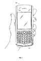
- FIG. 1 illustrates a mobile communication device configured
- FIG. 2 is an exploded view of a mobile communication device
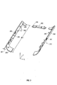
- FIG. 3 illustrates a first side piece, a second side piece, and a first cross piece of implementations of the technology.
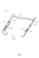
- FIG. 4 illustrates an outer piece of implementations of the technology.
- FIG. 5 illustrates an implementation of an assembly of the technology.
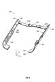
- FIG. 6 illustrates an implementation of an assembly of the technology as extracted from a mold.
- FIG. 7 illustrates methods of the technology.
- a mobile communication device 300 is illustrated.
- the mobile communication device 300 can comprise a display 322 located above a keyboard 332 suitable for accommodating textual input to the mobile communication device 300.
- the mobile communication device 300 can be of uni-body construction, also known as a "candy-bar" design.
- the mobile communication device 300 can be a flip-type phone or a slider-type as well.
- FIG. 2 illustrates some typical components that can be found in the assembly of the mobile electronic device 300.
- a support frame 101 cab constitute a base for many other components of the mobile communication device 300.
- the assembly can interconnect right side element 105, left side element 106, top element 107, and bottom element 108 with the support frame 101.
- Elements 106-108 typically can be substantially rigid.
- elements 106-108 can be formed of polycarbonate material. Such material can provide protection and strength to the support structure of the mobile communication device 300. Such material also can draw heat away from the interior of the mobile communication device through heatstaking.
- the material can be used to frame i) buttons (e.g., 130, 131, 132, 133) that can be attached to switches (not shown in FIG. 2 ), ii) input/output ports (for example, Universal Serial Bus (USB) port 330), and iii) jacks (for example, audio jack 140) via apertures in the elements.
- buttons e.g., 130, 131
- Injection molding is a manufacturing process for producing parts from both thermoplastic and thermosetting plastic materials. Material is fed into a heated barrel, mixed, and forced into a mold cavity where the material cools and hardens to the configuration of the mold cavity. After a product is designed, usually by an industrial designer or an engineer, molds are made by a moldmaker (or toolmaker) from metal, usually either steel or aluminium, and precision-machined to form the features of the desired part. Injection molding is widely used for manufacturing a variety of parts, from the smallest component to entire body panels of cars.
- Injection molding is used to create many things such as wire spools, packaging, bottle caps, automotive dashboards, pocket combs, and most other plastic products available today. Injection molding is the most common method of part manufacturing. Injection molding is useful for producing high volumes of the same object. Some advantages of injection molding are high production rates, repeatable high tolerances, the ability to use a wide range of materials, low labor cost, minimal scrap losses, and little need to finish parts after molding. Some disadvantages of this process are expensive equipment investment, potentially high running costs, and the need to design moldable parts.
- thermoplastics including all thermoplastics, some thermosets, and some elastomers.
- thermosets including all thermoplastics, some thermosets, and some elastomers.
- the available materials are alloys or blends of previously developed materials meaning that product designers can choose from a vast selection of materials, one that has exactly the right properties. Materials are chosen based on the strength and function required for the final part but also each material has different parameters for molding that must be taken into account.
- Common polymers like Epoxy and phenolic are examples of thermosetting plastics while nylon, polyethylene, and polystyrene are thermoplastic
- the edges of mobile communication device 300 present a substantially discontinuous and substantially hard surface to a user.
- the mobile communication device 300 may be held by the sides, and buttons, e.g., 130, 131, at the top of the mobile communication device 300 may be engaged.
- the apertures for buttons for example, apertures through top element 107, can present openings for ingress of fluids and particles.
- the apertures can expose the buttons, the ports, and the jacks to the possibility of being inadvertently becoming detached, for example, by being pried loose from the mobile communication device.
- the discontinuous hard tactile experience can be a disadvantage not only from an aesthetic perspective, but also from a functional perspective.
- the hard surface may be more difficult to grasp securely.
- the possibility for ingress of fluids and particles presents another functional disadvantage to the use of a discontinuous hard tactile surface.
- the possibility for device components becoming detached can be seen as a disadvantage in the design of mobile communication device 300.
- Implementations of the present technology coat at least two adjacent elements from among, e.g., 105-108, with a flexible, softer, more tactile, material that presents a continuous surface.
- This continuous surface also is sufficiently flexible to allow switches to be activate through the softer material covering the apertures in the underlying substantially rigid pieces.
- at least one gap is created between the underlying rigid pieces to allow for at least one molding configuration to facilitate manufacturing, and at least one installed configuration that can include features that would otherwise inhibit manufacturing.
- the assembly can be altered between the molding configuration and the installed configuration by flexing the flexible material.
- first side piece 360 can be seen as analogous to the left side element 106 of FIG. 2 .
- the second side piece 370 can be seen as analogous to the right side element 105 of FIG. 2 .
- the first cross piece 380 can be seen as analogous to the top element 107 of FIG. 2 .
- the first side piece 360 and second side piece 370 can be formed of substantially rigid material.
- a polycarbonate material can be used to form first side piece 360 and second side piece 370.
- all kind of plastic materials can be used as long as the material has good adhesion to the substantially flexible outer component (to be described below).
- Each of first side piece 360 and second side piece 370 can have a substantially similar base thickness (e.g., 361), short primary dimension (e.g., 362), long primary dimension (e.g., 363), an inner face (e.g., 364), and an outer face (e.g., 365).
- Each of first side piece 360 and second side piece 370 can have heat staking pins 366 and apertures 367 for access to switches, jacks, and input/output ports.
- each of first side piece 360 and second side piece 370 has a curved portion 368 corresponding to a transition between the side of a mobile communication device 300 and a back face or a front face of the mobile communication device 300.
- the first side piece 360 can be curved along the first side piece 360 short dimension (i.e., with a radius center toward the other side piece in an installed configuration).
- the second side piece 370 can be curved along the second side piece short dimension (i.e., with a radius center toward the other side piece in an installed configuration).
- the first cross piece 380 can be formed from the same material as the first side piece 360 and the second side piece 370, or the first cross piece 380 can be formed from any other suitable substantially rigid material having good adhesion to the outer component. Like the first side pieces 360 and the second side piece 370, the first cross piece 380 can have a thickness that is less than the first cross piece 380 short primary dimension, and the first cross piece 380 can have a short dimension that is less than the first cross piece 380 long primary dimension, along with heat stakes 366. In the illustrated implementation, In some implementations, the cross piece 380 can have apertures and guide features. In some implementations, a second cross piece can be included in the assembly between the side pieces, e.g., at the end distal from the first cross piece.
- the outer piece 400 can be formed from substantially flexible material.
- a thermoplastic elastomer (TPE), a thermoplastic polyurethane (TPU) can be used to form the outer piece 400.
- the illustrated outer piece 400 has a first side portion 410, a second side portion 420, and a first spanning portion 430.
- the outer piece includes a additional spanning portions spanning the distance between the side pieces.
- a second spanning portion can be located at the opposite end from spanning portion 430.
- the spanning portion(s) can be located at other points along the long primary dimension of the side pieces and can be oriented other than normal to one more side pieces.
- spanning portions can be configured as diagonal pieces.
- the illustrated cross piece 400 has an inner face 440 and an outer face 450.
- first side piece 410 and second side piece 420 each can include at least one button feature 460.
- the second side piece 420 includes a port skirt feature 470, and apertures 480.
- a button feature 460 is shown in the implementation illustrated in FIG. 4 .
- the button feature 460 can include region 460a on the outer piece outer surface.
- the button feature 460 also can includes post 460b.
- Post 460b is in the direction of the outer piece inner surface 440.
- Post 460b can activate a switch in the mobile communication device 300 when the outer piece outer surface 450 is depressed at the region 460a.
- FIG. 5 an implementation of an assembled configuration 500 of a trim assembly of the technology in an installed orientation is illustrated.
- First side piece 360, second side piece 370, and first cross piece 380 are shown positioned abuttingly "inside" (i.e., closer to the interior of a mobile communication device 300 that the piece can be used in) outer piece 400 with the edges of the respective pieces substantially aligned.
- the example of FIG. 5 includes reference numerals to various aspects of the pieces 360, 370, 380, 400 described elsewhere herein.
- the outer piece outer face 450 can form the outer face of the assembled configuration 500.
- the substantially rigid inner faces of the first side piece 360, the second side piece 370, and the first cross piece 380 can form part of the inner face of the assembly.
- the remaining part of the inner face of the assembly can be formed by segments, 430a and 430b, of the substantially flexible outer assembly spanning portion inner face 430. While in the illustrated implementation the flexible regions, region 430a and region 430b, of the assembly 500 can be disposed substantially symmetric about the first cross piece 380, other implementations have only a single exposed flexible region, or multiple exposed flexible regions disposed symmetrically or asymmetrically.
- the substantially flexible outer piece 400 can be pressed at region 460a as described above to activate corresponding switches in a mobile communication device 300 when the assembly is installed on the mobile communication device 300.
- apertures e.g., 480 can accept interface structures (e.g., USB connectors) from outside the mobile communication device 300 for connection to a device port(s) exposed through the aperture.
- the apertures can have removable covers (for example made of the same material as the outer piece) flexibly attached to the outer piece 400.
- heat staking pins 366 can be used to attach the assembly to a mobile communication device 300 and facilitate the conduction of heat from the interior of the mobile communication device toward the exterior of the mobile communication device.
- Some implementations of the assembly include a second spanning portion of the outer piece and a second cross piece between the respective side pieces and side portions.
- the cross piece 380 is substantially centered on the outer piece spanning portion 430, exposing flexible regions 430a and 430b.
- placement of cross pieces can create one, or more than two, regions of flexibility in the assembly, and can create asymmetrical arrangements of such regions.
- FIG. 6 a molding configuration 600 of the assembly is shown.
- Several features identified in FIG. 1 through FIG. 5 are indicated in FIG. 6 as reference points.
- Substantially flexible regions 430a and 430b are bent generally about the ⁇ -axis when compared to the installed configuration 500.
- the assembly orients most features substantially in the direction of the z-axis, facilitating removal of the assembly from a mold cavity.
- the assembly is formed, e.g., via a 2-shot molding process, in a molding configuration 710, i.e., with flexible regions 430a and 430b flexed to facilitate removal from the mold cavity.
- the assembly is configured 720 to an assembled configuration 500 on the mobile communication device 300.
- the trim assembly is molded in a molding configuration such that the elements of the assembly are oriented for substantially unidirectional withdrawal from the mold cavity after the second shot. This reduces, if not eliminates, the need for technology such as sliders; giving no slider-caused witness lines. This approach is possible, at least in part because of flexible portions of the outer piece.
Landscapes
- Engineering & Computer Science (AREA)
- Signal Processing (AREA)
- Telephone Set Structure (AREA)
- Injection Moulding Of Plastics Or The Like (AREA)
Priority Applications (1)
| Application Number | Priority Date | Filing Date | Title |
|---|---|---|---|
| CA 2735492 CA2735492C (en) | 2010-05-06 | 2011-03-30 | Molded assembly |
Applications Claiming Priority (1)
| Application Number | Priority Date | Filing Date | Title |
|---|---|---|---|
| US33209910P | 2010-05-06 | 2010-05-06 |
Publications (2)
| Publication Number | Publication Date |
|---|---|
| EP2385683A2 true EP2385683A2 (de) | 2011-11-09 |
| EP2385683A3 EP2385683A3 (de) | 2014-02-26 |
Family
ID=44278690
Family Applications (1)
| Application Number | Title | Priority Date | Filing Date |
|---|---|---|---|
| EP20100187928 Withdrawn EP2385683A3 (de) | 2010-05-06 | 2010-10-18 | Formanordnung |
Country Status (3)
| Country | Link |
|---|---|
| US (1) | US8373985B2 (de) |
| EP (1) | EP2385683A3 (de) |
| CA (1) | CA2735492C (de) |
Cited By (1)
| Publication number | Priority date | Publication date | Assignee | Title |
|---|---|---|---|---|
| WO2013186597A1 (en) * | 2012-06-15 | 2013-12-19 | Nokia Corporation | A display suspension |
Families Citing this family (6)
| Publication number | Priority date | Publication date | Assignee | Title |
|---|---|---|---|---|
| US8817467B2 (en) * | 2012-05-31 | 2014-08-26 | Yia-Yuan Ore Yang | Sliding protective device for an electronic product |
| CN103491738B (zh) * | 2012-06-11 | 2016-07-13 | 鸿富锦精密工业(深圳)有限公司 | 壳体结构及采用该壳体结构的电子装置 |
| US9146588B2 (en) * | 2012-09-30 | 2015-09-29 | Apple Inc. | Systems and methods for securing components of an electronic device |
| TW201431461A (zh) * | 2013-01-24 | 2014-08-01 | Hon Hai Prec Ind Co Ltd | 電子裝置 |
| JP6191338B2 (ja) * | 2013-09-04 | 2017-09-06 | ソニー株式会社 | 筐体および筐体部品 |
| WO2016007177A1 (en) * | 2014-07-11 | 2016-01-14 | Apple Inc. | Retention system for dynamic loading |
Family Cites Families (41)
| Publication number | Priority date | Publication date | Assignee | Title |
|---|---|---|---|---|
| US4225970A (en) * | 1978-11-24 | 1980-09-30 | Motorola, Inc. | Splash proof portable two-way data terminal/radio |
| CA2150604A1 (en) | 1994-06-02 | 1995-12-03 | Ralph W. Welsh | Injection molding apparatus, method and product |
| US5568357A (en) * | 1994-06-15 | 1996-10-22 | Metanetics Corporation | Display support having cradled damping caps for floating core shock absorption |
| US5613237A (en) * | 1994-10-17 | 1997-03-18 | Motorola, Inc. | Housing latch system utilizing an elastomeric interlocking band |
| CA2148966C (en) | 1995-02-09 | 1997-03-04 | Werner Scheliga | Seamless molded skirt and process |
| DE19640629A1 (de) | 1996-10-01 | 1998-04-02 | Zeller Plastik Koehn Graebner | Verschlussmembran |
| US6028765A (en) * | 1997-06-19 | 2000-02-22 | Xplore Technologies, Inc. | Removable hand-grips for a portable pen-based computer |
| US6388877B1 (en) * | 1999-02-04 | 2002-05-14 | Palm, Inc. | Handheld computer with open accessory slot |
| US6159532A (en) | 1999-06-16 | 2000-12-12 | Mapa Pioneer Corporation | Method for making polymeric glove with thin, fluoroelastomeric coating |
| US6998174B2 (en) | 2000-02-24 | 2006-02-14 | Conix Corporation | Integrated co-injection molded vehicle components and methods of making the same |
| US6437238B1 (en) * | 2001-02-28 | 2002-08-20 | Palm, Inc. | Laminated housing for a portable hand held device |
| US7012189B2 (en) * | 2001-03-28 | 2006-03-14 | Apple Computer, Inc. | Computer enclosure |
| US7663879B2 (en) * | 2001-11-19 | 2010-02-16 | Otter Products, Llc | Protective enclosure for personal digital assistant case having integrated back lighted keyboard |
| US7427193B2 (en) | 2001-12-04 | 2008-09-23 | Callaway Golf Company | Method and apparatus for forming a golf ball |
| KR100955545B1 (ko) * | 2002-03-28 | 2010-04-30 | 산요덴키가부시키가이샤 | 액정 표시 장치 |
| TW540286B (en) * | 2002-08-07 | 2003-07-01 | Quanta Comp Inc | Buffer device |
| WO2005006717A1 (en) * | 2003-07-08 | 2005-01-20 | Nokia Corporation | Handheld electronic device casing element |
| JP4207813B2 (ja) | 2003-11-27 | 2009-01-14 | 豊田合成株式会社 | 頭部保護エアバッグ |
| JP3857703B2 (ja) | 2004-08-19 | 2006-12-13 | 株式会社日本製鋼所 | 成形体の製造方法および製造装置 |
| US7710714B2 (en) * | 2004-09-13 | 2010-05-04 | Bettcher Industries, Inc. | Housing for scale or load cell controller |
| US7382567B2 (en) | 2005-05-09 | 2008-06-03 | Analog Devices, Inc. | Accelerometer-based differential free fall detection system, apparatus, and method and disk drive protection mechanism employing same |
| TWI367660B (en) * | 2006-01-20 | 2012-07-01 | Fih Hong Kong Ltd | Ariproof structure for a portable electronic device |
| CN101018458A (zh) * | 2006-02-10 | 2007-08-15 | 深圳富泰宏精密工业有限公司 | 便携式电子装置密封结构 |
| KR101385231B1 (ko) * | 2006-08-24 | 2014-04-14 | 삼성디스플레이 주식회사 | 평판표시장치 |
| US20080057286A1 (en) | 2006-08-30 | 2008-03-06 | Polk Dale E | Method of forming a molded plastic article having at least one molded extension |
| US7837917B2 (en) | 2006-08-30 | 2010-11-23 | Lrm Industries International, Inc. | Method of forming a molded plastic article having molded extensions |
| US7706837B2 (en) * | 2006-09-01 | 2010-04-27 | Research In Motion Limited | Disabling operation of a camera on a handheld mobile communication device based upon enabling or disabling devices |
| KR100877049B1 (ko) * | 2006-09-28 | 2009-01-07 | 가시오 히타치 모바일 커뮤니케이션즈 컴퍼니 리미티드 | 방수구조 |
| TWI327431B (en) * | 2006-10-05 | 2010-07-11 | Asustek Comp Inc | Mobile phone back cover assembly structure |
| WO2008053527A1 (en) | 2006-10-31 | 2008-05-08 | Fujitsu Limited | Electronic equipment housing and process for manufacturing the same |
| JP4538483B2 (ja) * | 2007-10-23 | 2010-09-08 | 株式会社カシオ日立モバイルコミュニケーションズ | 防水構造及び電子機器 |
| CN101426348B (zh) * | 2007-11-02 | 2011-05-04 | 鸿富锦精密工业(深圳)有限公司 | 便携式电子装置保护壳 |
| US20090141436A1 (en) * | 2007-11-30 | 2009-06-04 | Yoshimichi Matsuoka | Trim element for housing of computing device |
| CN101472409A (zh) * | 2007-12-28 | 2009-07-01 | 旭丽电子(广州)有限公司 | 电子装置壳体 |
| US8101859B2 (en) * | 2008-01-03 | 2012-01-24 | Apple Inc. | Metal retaining features for handheld electronic device casing |
| JP2009278411A (ja) * | 2008-05-15 | 2009-11-26 | Sony Ericsson Mobilecommunications Japan Inc | 携帯装置 |
| US7697281B2 (en) * | 2008-09-05 | 2010-04-13 | Apple Inc. | Handheld computing device |
| CN101666896B (zh) * | 2008-09-05 | 2014-04-30 | 深圳富泰宏精密工业有限公司 | 具有视窗镜片的壳体组件 |
| JP5110032B2 (ja) * | 2009-04-17 | 2012-12-26 | 富士通株式会社 | 筐体 |
| CN102006738A (zh) * | 2009-09-03 | 2011-04-06 | 鸿富锦精密工业(深圳)有限公司 | 壳体 |
| CN102006747B (zh) * | 2009-09-03 | 2015-07-29 | 鸿富锦精密工业(深圳)有限公司 | 壳体 |
-
2010
- 2010-10-18 US US12/906,535 patent/US8373985B2/en active Active
- 2010-10-18 EP EP20100187928 patent/EP2385683A3/de not_active Withdrawn
-
2011
- 2011-03-30 CA CA 2735492 patent/CA2735492C/en active Active
Non-Patent Citations (1)
| Title |
|---|
| None |
Cited By (3)
| Publication number | Priority date | Publication date | Assignee | Title |
|---|---|---|---|---|
| WO2013186597A1 (en) * | 2012-06-15 | 2013-12-19 | Nokia Corporation | A display suspension |
| US10168737B2 (en) | 2012-06-15 | 2019-01-01 | Nokia Technologies Oy | Display suspension |
| US10747268B2 (en) | 2012-06-15 | 2020-08-18 | Nokia Technologies Oy | Display suspension |
Also Published As
| Publication number | Publication date |
|---|---|
| US20110273823A1 (en) | 2011-11-10 |
| EP2385683A3 (de) | 2014-02-26 |
| CA2735492A1 (en) | 2011-11-06 |
| CA2735492C (en) | 2013-10-01 |
| US8373985B2 (en) | 2013-02-12 |
Similar Documents
| Publication | Publication Date | Title |
|---|---|---|
| CA2735492C (en) | Molded assembly | |
| KR101353749B1 (ko) | 누름버튼 스위치의 제조방법 | |
| US7586038B2 (en) | Electrical junction box and assembling method thereof | |
| US8190222B2 (en) | Housing for electronic device | |
| US6571457B2 (en) | Control panel for electronic equipment and method of producing the same | |
| US8247059B2 (en) | Two-color molded product | |
| KR101910839B1 (ko) | 음향출력부를 구비하는 전자기기 | |
| KR101100081B1 (ko) | 전자제품용 수지 일체형 금속 케이스 및 그 제조방법 | |
| CN101573009A (zh) | 电子装置壳体及其制造方法 | |
| US20110223382A1 (en) | Housing structure | |
| CN101296584B (zh) | 便携式电子装置机壳的制造方法 | |
| CN101616560B (zh) | 金属壳体及其制造方法 | |
| JPH05124060A (ja) | 樹脂成形体及びその製造方法 | |
| US7102090B2 (en) | Front panel having push buttons formed integrally therewith | |
| US7404996B2 (en) | Two-shot polymeric component with attachment feature and method of producing same | |
| US20080138586A1 (en) | Hybrid structure and method | |
| KR200484625Y1 (ko) | 도어락의 케이스 구조체 | |
| US20130148277A1 (en) | Electronic device | |
| CN213305695U (zh) | 一种组合式麦克风网罩 | |
| KR101977141B1 (ko) | 금속질감을 표현한 사출모재 | |
| US20110042400A1 (en) | Housing of portable electronic device | |
| JP2002044828A (ja) | コードガイド | |
| CN222832912U (zh) | 一种车门立柱板结构 | |
| CN101729954B (zh) | 音腔结构 | |
| JPH0213241Y2 (de) |
Legal Events
| Date | Code | Title | Description |
|---|---|---|---|
| 17P | Request for examination filed |
Effective date: 20101018 |
|
| AK | Designated contracting states |
Kind code of ref document: A2 Designated state(s): AL AT BE BG CH CY CZ DE DK EE ES FI FR GB GR HR HU IE IS IT LI LT LU LV MC MK MT NL NO PL PT RO RS SE SI SK SM TR |
|
| AX | Request for extension of the european patent |
Extension state: BA ME |
|
| PUAI | Public reference made under article 153(3) epc to a published international application that has entered the european phase |
Free format text: ORIGINAL CODE: 0009012 |
|
| RAP1 | Party data changed (applicant data changed or rights of an application transferred) |
Owner name: BLACKBERRY LIMITED |
|
| RAP1 | Party data changed (applicant data changed or rights of an application transferred) |
Owner name: BLACKBERRY LIMITED |
|
| PUAL | Search report despatched |
Free format text: ORIGINAL CODE: 0009013 |
|
| AK | Designated contracting states |
Kind code of ref document: A3 Designated state(s): AL AT BE BG CH CY CZ DE DK EE ES FI FR GB GR HR HU IE IS IT LI LT LU LV MC MK MT NL NO PL PT RO RS SE SI SK SM TR |
|
| AX | Request for extension of the european patent |
Extension state: BA ME |
|
| RIC1 | Information provided on ipc code assigned before grant |
Ipc: H05K 5/00 20060101ALI20140122BHEP Ipc: H04M 1/02 20060101AFI20140122BHEP |
|
| 17Q | First examination report despatched |
Effective date: 20150309 |
|
| STAA | Information on the status of an ep patent application or granted ep patent |
Free format text: STATUS: THE APPLICATION IS DEEMED TO BE WITHDRAWN |
|
| 18D | Application deemed to be withdrawn |
Effective date: 20150721 |