EP2384022A2 - Kopfhörersystem für eine mobile Vorrichtung und Betriebsverfahren dafür - Google Patents
Kopfhörersystem für eine mobile Vorrichtung und Betriebsverfahren dafür Download PDFInfo
- Publication number
- EP2384022A2 EP2384022A2 EP11163906A EP11163906A EP2384022A2 EP 2384022 A2 EP2384022 A2 EP 2384022A2 EP 11163906 A EP11163906 A EP 11163906A EP 11163906 A EP11163906 A EP 11163906A EP 2384022 A2 EP2384022 A2 EP 2384022A2
- Authority
- EP
- European Patent Office
- Prior art keywords
- earphone
- input signal
- mobile device
- input
- ear jack
- Prior art date
- Legal status (The legal status is an assumption and is not a legal conclusion. Google has not performed a legal analysis and makes no representation as to the accuracy of the status listed.)
- Granted
Links
Images




Classifications
-
- G—PHYSICS
- G09—EDUCATION; CRYPTOGRAPHY; DISPLAY; ADVERTISING; SEALS
- G09G—ARRANGEMENTS OR CIRCUITS FOR CONTROL OF INDICATING DEVICES USING STATIC MEANS TO PRESENT VARIABLE INFORMATION
- G09G5/00—Control arrangements or circuits for visual indicators common to cathode-ray tube indicators and other visual indicators
- G09G5/12—Synchronisation between the display unit and other units, e.g. other display units, video-disc players
-
- H—ELECTRICITY
- H04—ELECTRIC COMMUNICATION TECHNIQUE
- H04R—LOUDSPEAKERS, MICROPHONES, GRAMOPHONE PICK-UPS OR LIKE ACOUSTIC ELECTROMECHANICAL TRANSDUCERS; ELECTRIC HEARING AIDS; PUBLIC ADDRESS SYSTEMS
- H04R1/00—Details of transducers, loudspeakers or microphones
- H04R1/10—Earpieces; Attachments therefor ; Earphones; Monophonic headphones
- H04R1/1041—Mechanical or electronic switches, or control elements
-
- G—PHYSICS
- G06—COMPUTING OR CALCULATING; COUNTING
- G06F—ELECTRIC DIGITAL DATA PROCESSING
- G06F1/00—Details not covered by groups G06F3/00 - G06F13/00 and G06F21/00
- G06F1/26—Power supply means, e.g. regulation thereof
- G06F1/32—Means for saving power
- G06F1/3203—Power management, i.e. event-based initiation of a power-saving mode
- G06F1/3206—Monitoring of events, devices or parameters that trigger a change in power modality
- G06F1/3215—Monitoring of peripheral devices
-
- G—PHYSICS
- G06—COMPUTING OR CALCULATING; COUNTING
- G06F—ELECTRIC DIGITAL DATA PROCESSING
- G06F1/00—Details not covered by groups G06F3/00 - G06F13/00 and G06F21/00
- G06F1/26—Power supply means, e.g. regulation thereof
- G06F1/32—Means for saving power
- G06F1/3203—Power management, i.e. event-based initiation of a power-saving mode
- G06F1/3234—Power saving characterised by the action undertaken
- G06F1/325—Power saving in peripheral device
- G06F1/3265—Power saving in display device
-
- G—PHYSICS
- G09—EDUCATION; CRYPTOGRAPHY; DISPLAY; ADVERTISING; SEALS
- G09G—ARRANGEMENTS OR CIRCUITS FOR CONTROL OF INDICATING DEVICES USING STATIC MEANS TO PRESENT VARIABLE INFORMATION
- G09G5/00—Control arrangements or circuits for visual indicators common to cathode-ray tube indicators and other visual indicators
- G09G5/10—Intensity circuits
-
- H—ELECTRICITY
- H04—ELECTRIC COMMUNICATION TECHNIQUE
- H04R—LOUDSPEAKERS, MICROPHONES, GRAMOPHONE PICK-UPS OR LIKE ACOUSTIC ELECTROMECHANICAL TRANSDUCERS; ELECTRIC HEARING AIDS; PUBLIC ADDRESS SYSTEMS
- H04R5/00—Stereophonic arrangements
- H04R5/04—Circuit arrangements, e.g. for selective connection of amplifier inputs/outputs to loudspeakers, for loudspeaker detection, or for adaptation of settings to personal preferences or hearing impairments
-
- G—PHYSICS
- G09—EDUCATION; CRYPTOGRAPHY; DISPLAY; ADVERTISING; SEALS
- G09G—ARRANGEMENTS OR CIRCUITS FOR CONTROL OF INDICATING DEVICES USING STATIC MEANS TO PRESENT VARIABLE INFORMATION
- G09G2320/00—Control of display operating conditions
- G09G2320/06—Adjustment of display parameters
- G09G2320/0626—Adjustment of display parameters for control of overall brightness
-
- G—PHYSICS
- G09—EDUCATION; CRYPTOGRAPHY; DISPLAY; ADVERTISING; SEALS
- G09G—ARRANGEMENTS OR CIRCUITS FOR CONTROL OF INDICATING DEVICES USING STATIC MEANS TO PRESENT VARIABLE INFORMATION
- G09G2320/00—Control of display operating conditions
- G09G2320/06—Adjustment of display parameters
- G09G2320/0686—Adjustment of display parameters with two or more screen areas displaying information with different brightness or colours
-
- G—PHYSICS
- G09—EDUCATION; CRYPTOGRAPHY; DISPLAY; ADVERTISING; SEALS
- G09G—ARRANGEMENTS OR CIRCUITS FOR CONTROL OF INDICATING DEVICES USING STATIC MEANS TO PRESENT VARIABLE INFORMATION
- G09G2320/00—Control of display operating conditions
- G09G2320/08—Arrangements within a display terminal for setting, manually or automatically, display parameters of the display terminal
-
- G—PHYSICS
- G09—EDUCATION; CRYPTOGRAPHY; DISPLAY; ADVERTISING; SEALS
- G09G—ARRANGEMENTS OR CIRCUITS FOR CONTROL OF INDICATING DEVICES USING STATIC MEANS TO PRESENT VARIABLE INFORMATION
- G09G2330/00—Aspects of power supply; Aspects of display protection and defect management
- G09G2330/02—Details of power systems and of start or stop of display operation
- G09G2330/021—Power management, e.g. power saving
-
- G—PHYSICS
- G09—EDUCATION; CRYPTOGRAPHY; DISPLAY; ADVERTISING; SEALS
- G09G—ARRANGEMENTS OR CIRCUITS FOR CONTROL OF INDICATING DEVICES USING STATIC MEANS TO PRESENT VARIABLE INFORMATION
- G09G2370/00—Aspects of data communication
- G09G2370/22—Detection of presence or absence of input display information or of connection or disconnection of a corresponding information source
-
- H—ELECTRICITY
- H04—ELECTRIC COMMUNICATION TECHNIQUE
- H04R—LOUDSPEAKERS, MICROPHONES, GRAMOPHONE PICK-UPS OR LIKE ACOUSTIC ELECTROMECHANICAL TRANSDUCERS; ELECTRIC HEARING AIDS; PUBLIC ADDRESS SYSTEMS
- H04R2420/00—Details of connection covered by H04R, not provided for in its groups
- H04R2420/05—Detection of connection of loudspeakers or headphones to amplifiers
Definitions
- the present invention relates to a mobile device having an ear jack interface. More particularly, the present invention relates to an earphone system and operation method thereof for identifying various input signals offered from an earphone connected to the ear jack interface and thereby for controlling a particular user-function in response to the identified signal.
- a mobile device denotes a type of electronic device that provides mobility and portability.
- mobile devices such as a mobile communication device and a Personal Digital Assistant (PDA)
- PDA Personal Digital Assistant
- a typical mobile communication device has a module for supporting a mobile communication function and thereby allows voice and data communications with other mobile communication devices through a base station.
- a typical PDA has a Central Processing Unit (CPU), a memory unit, an Operating System (OS), and various programs and modules that operate based on the OS, and thereby allows various functions to collect, store, write and search information.
- CPU Central Processing Unit
- OS Operating System
- Some functions of the mobile device e.g., a call function, an audio file play function, etc., inherently include a function to output audio signals through a speaker provided on the mobile device.
- a user of the mobile device may use an earphone to prevent sounds from being heard outside or to hear clearer sounds.
- a conventional mobile device typically includes a 4-pole ear jack interface.
- this 4-pole ear jack interface only supports an audio signal output through right and left earphone speakers and an audio signal input through an earphone microphone.
- the 4-pole ear jack interface merely recognizes the insertion of an earphone and then only performs audio input and output. Therefore, the utilization of such a conventional ear jack interface is limited. Even if any external device can be connected to the 4-pole ear jack interface, this may unfavorably cause great power consumption since a conventional mobile device should always monitor a connection of an external device by continuously detecting the value of an Analog Digital Converter (ADC) received through the ear jack interface.
- ADC Analog Digital Converter
- an aspect of the present invention is to provide an earphone system, a mobile device for supporting the earphone system, and an operation method for the earphone system, allowing various input elements to be connected to an ear jack interface of the mobile device with reduced power consumption.
- an earphone system includes an earphone including a 4-pole earphone header and an earphone input unit, the earphone header having an earphone microphone terminal, and the earphone input unit being configured to create at least one input signal for the control of a user-function of a mobile device and to send the at least one input signal to the mobile device through the earphone microphone terminal, and the mobile device including an ear jack interface including a microphone electrode pin, the mobile device being configured to receive the at least one input signal through the microphone electrode pin when the ear jack interface is connected to the earphone header, to identify the received at least one input signal, and to control the user-function corresponding to the at least one identified input signal.
- a mobile device includes an ear jack interface for reception of a 4-pole earphone header of an earphone, the ear jack interface including a microphone electrode pin for connection to an earphone microphone terminal of the earphone header, and a control unit configured to receive at least one input signal through the microphone electrode pin, the input signal being created by earphone input elements of the earphone, to identify the received input signal, and to control a particular user-function corresponding to the identified input signal.
- a method for operating an earphone system includes determining whether a 4-pole earphone header of an earphone is inserted into an ear jack interface, receiving at least one input signal from earphone input elements of the earphone through the earphone header, identifying the received at least one input signal through the ear jack interface, and controlling a particular user-function in response to the identified at least one input signal.
- FIG. 1 is a perspective view illustrating an earphone system in accordance with an exemplary embodiment of the present invention.
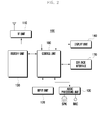
- FIG. 2 is a block diagram illustrating a configuration of a mobile device in accordance with an exemplary embodiment of the present invention.
- FIG. 3 is a schematic view illustrating an ear jack interface and an earphone in the earphone system in accordance with an exemplary embodiment of the present invention.
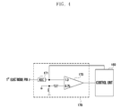
- FIG. 4 is a schematic view illustrating signal identification in an ear jack interface in accordance with an exemplary embodiment of the present invention.
- FIGs. 5 and 6 are flow diagrams illustrating a method for operating an ear phone system in accordance with an exemplary embodiment of the present invention.
- FIG. 1 is a perspective view illustrating an earphone system in accordance with an exemplary embodiment of the present invention.
- the earphone system is composed of a mobile device 100 and an earphone 200.
- the following disclosure is based on the earphone 200 connected to an ear jack interface of the mobile device 100, this is exemplary only and not to be considered as a limitation of the present invention.
- any other equivalents such as an external speaker, can be connected to the ear jack interface.
- the mobile device 100 includes a display unit 140 and an ear jack interface 170 and may transmit or receive audio signals, generated during a content playback or a voice call, to or from the earphone 200 through the ear jack interface 170. While connected to the earphone 200, the mobile device 100 may identify signals created by and received from various input elements, such as volume up/down keys and call/stop keys, provided in the earphone 200. Also, the mobile device 100 may control a particular user-function in response to the identified signal. The mobile device 100 may recognize the connection of the earphone 200 from an interrupt created when a header of the earphone 200 is inserted into the ear jack interface 170, and may support particular functions related to the earphone 200. Each individual element of the mobile device 100 will be described in more detail with reference to FIG. 2 below.
- the earphone 200 is a device that is connected to the ear jack interface 170 of the mobile device 100.
- the earphone 200 receives audio signals from the mobile device 100 and converts the received audio signals into sounds.
- the earphone 200 of a 4-pole type may have an earphone header 210 that is inserted into the ear jack interface 170, an earphone input unit 220 that has an earphone microphone (EAR-MIC), volume up/down keys 221, call/stop keys 223, and the like, and an earphone speaker 230 that may have left and right earphone speakers 231 and 233.
- the earphone 200 acquires sounds and converts them into audio signals through the earphone microphone (EAR-MIC) and delivers the audio signals to the mobile device 100 through the earphone header 210.
- EAR-MIC earphone microphone
- each element of the earphone input unit 220 may be activated and form a specific path according to a user's manipulation. Namely, each activated element of the earphone 200 may establish a path having a specific resistance value. Also, depending on a voltage value that is varied according to differences in resistance values in each path, the mobile device 100 may determine which element is activated in the earphone 200. Related descriptions will be given later with reference to FIG. 3 .
- the earphone system supports functions of the earphone 200 based on an interrupt created when the earphone 200 is connected to the ear jack interface 170. Furthermore, the earphone system identifies various signals created by and received from various input elements, such as volume up/down keys and call/stop keys, provided in the earphone 200, and controls a particular user-function in response to the identified signal. Therefore, a user can easily adjust an audio volume, make a call, stop a call, etc., by manipulating the 4-pole earphone 200 without directly handing the mobile device 100.
- various input elements such as volume up/down keys and call/stop keys
- FIG. 2 is a block diagram illustrating a configuration of a mobile device in accordance with an exemplary embodiment of the present invention.
- the mobile device 100 of this invention may include a Radio Frequency (RF) unit 110, an input unit 120, an audio processing unit 130, a display unit 140, a memory unit 150, an ear jack interface 170, and a control unit 160.
- RF Radio Frequency
- the mobile device 100 having the above-specified elements is structured to create an interrupt when the earphone 200 is connected to the ear jack interface 170. When such an interrupt occurs, the mobile device 100 can shift an audio path to the earphone 200. Also, if any interrupt is caused by a voltage drop under a given value in the ear jack interface 170, the mobile device 100 can detect the magnitude of a voltage drop and thereby identify the type of an input signal created by and received from the earphone 200. The mobile device 100 can perform a particular user-function in response to the identified input signal of the earphone 200.Each individual element of the mobile device 100 will be described below in more detail.
- the RF unit 110 is a kind of communication module for supporting a mobile communication service of the mobile device 100.
- the RF unit 110 may employ a Global System for Mobile communication (GSM) module, a Code Division Multiple Access (CDMA) module, or the like according to the type of mobile communication service and, based on such a module, establishes a communication channel with a mobile communication system.
- GSM Global System for Mobile communication
- CDMA Code Division Multiple Access
- the RF unit 110 may include an RF transmitter that up-converts the frequency of an outgoing signal and amplifies the signal, an RF receiver that amplifies with low-noise an incoming signal and down-converts the frequency of the signal, and the like.
- the RF unit 110 may be essential or not according to the type of mobile device 100.
- the RF unit 110 is essential. However, in case of a monitor, a music player, etc. that requires no mobile communication function, the RF unit 110 may be omitted according to the designer's or manufacturer's intention.
- the RF unit 110 of this invention establishes a call channel with any other device in response to a user's manipulation and sends or receives audio signals to or from the other device.
- audio signals received by the RF unit 110 may be delivered to the earphone speaker 230 of the earphone 200 through the ear jack interface 170.
- the input unit 120 includes a plurality of input keys and function keys to receive a user's input action and to set various functions.
- the function keys may have navigation keys, side keys, shortcut keys, and any other special keys defined to perform particular functions. Additionally, the input unit 120 receives a user's key manipulation for controlling the mobile device 100, creates a corresponding input signal, and delivers it to the control unit 160.
- the input unit 120 may create various input signals for controlling user-functions of the mobile device 100 and send them to the control unit 160. For instance, depending on a user's manipulation, the input unit 120 may create an input signal for entering or selecting a desired phone number, an input signal for trying to connect a call based on the desired phone number, an input signal for selecting and playing a desired file stored in the memory unit 150, or the like, and deliver it to the control unit 160.
- the audio processing unit 130 may include a speaker (SPK) for outputting audio signals delivered from the control unit 160, and a microphone (MIC) for collecting audio signals while a particular application is running.
- SPK speaker
- MIC microphone
- the audio processing unit 130 may output audio signals received through the RF unit 110 or audio signals of selected content to the speaker (SPK). More particularly, before the earphone 200 is connected to the ear jack interface 170, the audio processing unit 130 forms audio output and input paths based on the speaker (SPK) and the microphone (MIC).
- the audio processing unit 130 removes the above paths based on the speaker (SPK) and the microphone (MIC) and forms new audio output and input paths based on the earphone-microphone (EAR-MIC) and the earphone speaker 230 in the earphone 200. Therefore, audio signals of the mobile device 100 may be output through the ear jack interface 170 of the mobile device 100 and the earphone speaker 230 of the earphone 200, and audio signals collected by the earphone microphone (EAR-MIC) may be input to the control unit 160 through the ear jack interface 170 and the audio processing unit 130.
- SPK speaker
- MIC earphone-microphone
- the display unit 140 represents information, including various menus of the mobile device 100, input by a user or offered to a user. Namely, the display unit 140 may visually offer a variety of screen views in connection with the use of the mobile device 100, such as an idle screen, a menu screen, a message writing screen, a call screen, and the like.
- the display unit 140 may enter into various states according to the connection of the ear jack interface 170. That is, when the earphone 200 is connected to the ear jack interface 170 during a call, the display unit 140 may be automatically turned off to minimize power consumption. If any input signal for instructing a supply of power is input, the display unit 140 may be turned on to again display the screen that was displayed just before being turned off. Additionally, when the earphone 200 is connected to the ear jack interface 170, the display unit 140 may output a given message or any other equivalents to announce the connection to a user. This function may be disabled at a user's request. Furthermore, if any input signal is delivered from the earphone 200, the display unit 140 may output a related screen.
- the display unit 140 may display a given image related to a selected input key to offer a feedback to a user. This function may also be disabled at a user's request.
- the display unit 140 may be formed of a Liquid Crystal Display (LCD), Organic Light Emitting Diodes (OLEDs), or any other equivalent.
- the display unit 140 may act as an input unit as well.
- the touch screen may be composed of a display panel and touch sensors disposed thereon.
- the mobile device 100 in this case may offer various menu screens available and suitable for the touch screen.
- the memory unit 150 stores a variety of applications required for functions related to an exemplary embodiment of this invention or required for execution or playback of various types of files. If the mobile device 100 employs a touch screen, the memory unit 150 may store a key map, a menu map, etc. required for the operation of the touch screen.
- the key map may have various well known types such as a keyboard map, a 3*4 key map, a QWERTY key map, or a special control key map suitable for the operation of a currently activated application.
- the menu map may be a special menu map suitable for the operation of a currently activated application or a normal menu map having menu items offered by the mobile device.
- the memory unit 150 may consist of a program region and a data region.
- the program region may store an Operating System (OS) for booting and operating the mobile device 100, and applications required for performing various functions or required for executing or playing various files, such as a call application, a web browser for surfing on the Internet, a Moving Picture Experts Group (MPEG) MPEG-1 or MPEG-2 Audio Layer III (MP3) application for playing digital sounds, an image viewer application for showing image files, a video player application, and the like. More particularly, the program region may store an earphone support application for supporting the function of the earphone 200.
- OS Operating System
- MPEG Moving Picture Experts Group
- MP3 MPEG-2 Audio Layer III
- the earphone support application is a specialized program that is activated when the earphone 200 is connected to the ear jack interface 170, controls the shift of an audio path toward the earphone 200, identifies an input signal received from the earphone 200, and controls a particular user-function based on the identified input signal.
- the earphone support application may be loaded in the control unit 160 and may contain a routine for determining whether the earphone 200 is connected to the ear jack interface 170, a routine for controlling the shift of audio output and input paths, a routine for identifying an input signal received from the earphone 200, and a routine for controlling a particular user-function in response to the identified input signal.
- the user-function control routine may have a subroutine for controlling specific options of a currently activated user-function and a subroutine for activating a selected user-function or inactivating the activated user-function.
- the data region stores data created or received while the mobile device 100 is used, and also may store various contents depending upon the type of the mobile device.
- the data region may store user's inputs received from the touch screen.
- the data region may store an input signal table used for controlling user-functions based on the connection of the earphone 200.
- the input signal table may define a mapping relation between types of input signals received from the earphone 200 and commands for executing user-functions.
- the input signal table may contain information about a command to increase a volume of a currently activated user-function in response to an input signal of the volume up key of the earphone 200.
- Such an input signal substantially corresponds to a specific voltage value, so the input signal table may be used for the creation of commands according to various voltage values.
- the ear jack interface 170 is provided on a side of the mobile device 100 in a form that allows the earphone header 210 to be inserted and then fixed.
- the ear jack interface 170 may have several pins such that various types of earphones can be used. A related description will be given later with reference to FIG. 3 .
- the control unit 160 controls a power supplying and initializing process for each element of the mobile device 100. After initializing, the control unit 160 may perform a control for a particular user-function selected in response to the connection of the earphone 200. More specifically, the control unit 160 may employ the above-discussed earphone support application and determine whether the earphone 200 is connected to the ear jack interface 170. For this, the mobile device 100 may equip the ear jack interface 170 with terminals or electrode pins for keeping a reference voltage. The mobile device 100 may recognize the connection of the earphone 200 by detecting a drop of the reference voltage caused by the connection of the earphone 200. Additionally, the control unit 160 may establish and control a signal path of the earphone 200 that is in contact with various electrode pins of the ear jack interface 170. A related description will be given hereinafter with reference to FIG. 3 .
- FIG. 3 is a schematic view illustrating an ear jack interface and an earphone in an earphone system in accordance with an exemplary embodiment of the present invention.
- the ear jack interface 170 may have five electrode pins denoted respectively by reference numbers 1, 2, 3, 4 and 5.
- the first electrode pin 1 is a microphone electrode pin to be connected to an earphone microphone terminal M of the earphone header 210.
- the second electrode pin 2 is a ground electrode pin to be connected to a ground terminal G of the earphone header 210.
- the third electrode pin 3 is a right speaker electrode pin to be connected to a right earphone speaker terminal R of the earphone header 210.
- the fourth electrode pin 4 is a left speaker electrode pin to be connected to a left earphone speaker terminal L of the earphone header 210.
- the fifth electrode pin 5 is an optional electrode pin to be connected to the ground terminal G of the earphone header 210. More particularly, the fifth electrode pin 5 may be used to generate an interrupt caused by the connection of the earphone 200. Namely, when the fifth electrode pin 5 is grounded through the connection of the earphone 200 under conditions where a given reference voltage is applied to the fifth electrode pin 5, the control unit 160 may determine that the earphone 200 is connected by recognizing a change of the reference voltage as an interrupt.
- the third and fourth electrode pins 3 and 4 may be connected to the same terminal of the earphone header 210 in some types of earphones 200. More specifically, if the earphone 200 is a stereo type, the third and fourth electrode pins 3 and 4 are connected respectively to the right and left earphone speaker terminals R and L which are separately formed. However, if the earphone 200 is a monaural type, the third and fourth electrode pins 3 and 4 may be connected to a single speaker terminal which is formed without distinguishing right and left speakers from each other. Nevertheless, since this invention is to identify input signals received through the earphone microphone terminal M, this invention may be applied to any type of earphone 200, namely, regardless of mono or stereo. In this disclosure, a stereo type of earphone 200 is exemplarily used.
- the earphone header 210 may have four terminals interconnected to the respective elements of the earphone 200. Specifically, the earphone header 210 may have the earphone microphone terminal M, the ground terminal G, the right earphone speaker terminal R, and the left earphone speaker terminal L. The right earphone speaker terminal R is interconnected to the right earphone speaker 231, and the left earphone speaker terminal L is interconnected to the left earphone speaker 233.
- the earphone-microphone terminal M is interconnected to each of the earphone-microphone (EAR-MIC), the volume up/down keys 221, and the call/stop keys 223 contained in the earphone input unit 220.
- the volume up/down keys 221 include a volume up key and a volume down key
- the call/stop keys 223 include a call key and a call stop key.
- each key is represented to be a resistance. Namely, the first resistance R1 indicates the volume up key, and the second resistance R2 indicates the volume down key. Similarly, the third resistance R3 indicates the call key, and the fourth resistance R4 indicates the call stop key. More particularly, the resistance of each key may be different in value from the others. As discussed above, when the earphone header 210 is inserted into the ear jack interface 170, it comes in contact with the respective electrode pins of the ear jack interface 170.
- FIG. 4 is a schematic view illustrating signal identification in an ear jack interface in accordance with an exemplary embodiment of the present invention.
- the ear jack interface 170 may have an Analog Digital Converter (ADC) 171 and a comparator 173.
- the ADC 171 is connected between the first electrode pin 1 of the ear jack interface 170 and the comparator 173.
- the comparator 173 compares a voltage delivered through the first electrode pin 1 with the reference voltage such that a selected user-function may be controlled according to comparison results. For instance, if only the earphone-microphone (EAR-MIC) is connected to the first electrode pin 1, an input value of the comparator 173 becomes about 1.3V. In this case, an audio signal input through the earphone-microphone (EAR-MIC) may be offered to the control unit 160 along a signal path.
- EAR-MIC an audio signal input through the earphone-microphone
- a voltage applied to the first electrode pin 1 through the earphone-microphone terminal M may be dropped under 1.3V due to the resistance of the selected key.
- the magnitude of a voltage drop may be adjusted through variations in resistance.
- the respective keys of the earphone input unit 220 may have different resistance values. Such resistance values may be adjusted to cause a voltage drop under the reference voltage (e.g., 0.75V) of the comparator 173.
- the comparator 173 may offer comparison results depending on such a voltage drop to the control unit 160.
- control unit 160 can recognize a selected key by detecting the magnitude of a voltage drop output from the comparator 173.
- the reference voltage of the comparator 173 may be varied according to a designer's intention.
- resistance values of the respective keys may be varied according to a designer's intention.
- the earphone system may identify various signals of the earphone input unit 220 in the earphone 200 when the 4-pole earphone 200 is connected, and may control a particular user-function in response to the identified signal.
- the earphone input unit 220 is described as having the volume up/down keys and the call/stop keys, this is exemplary only and not to be considered as a limitation of the present invention.
- the earphone input unit 220 may have any other various keys such as power turn-off key, a search key, etc.
- FIGs. 5 and 6 are flow diagrams illustrating a method for operating an ear phone system in accordance with an exemplary embodiment of the present invention. The following discussion will be focused on a process flow in the mobile device 100.
- the control unit 160 when power is supplied to the mobile device 100, the control unit 160 performs a booting process and initializes the respective elements of the mobile device 100. Then, based on predefined schedule information, the control unit 160 outputs an idle screen on the display unit 140 in step 501. If the schedule information contains instructions to activate a particular user-function, the control unit 160 may activate the user-function in this step according to the schedule information.
- the control unit 160 may determine whether the earphone 200 is connected to the ear jack interface 170 of the mobile device 100, namely whether the earphone header 210 is inserted into the ear jack interface 170. If it is determined in step 503 that there is no connection of the earphone 200, the control unit 160 may activate a selected user-function according to an input signal of the input unit 120 and then, based on the audio processing unit 130, control a processing of audio signals in step 505.
- the control unit 160 may shift current audio output and input paths to new paths based on the earphone 200 in step 507. Thereafter, the control unit 160 may determine whether an input signal for making a call is received from the earphone 200 in step 509. If so, the control unit 160 may try to make a call with the last phone number in a call history and also support a related user-function in step 511. In step 512, the control unit 160 may determine whether an input signal for stopping a call is received from the earphone 200. If so, the control unit 160 may return to step 509.
- control unit 160 may activate a selected user-function in response to any other input signal in step 513.
- step 515 the control unit 160 may determine whether an input signal corresponding to the volume up/down keys is received from the earphone 200. If so, the control unit 160 may increase or decrease a sound volume of a currently activated user-function in step 517. Then the control unit 160 may return to step 513.
- control unit 160 may further determine whether the earphone 200 is disconnected from the ear jack interface 170, namely whether the earphone header 210 is withdrawn from the ear jack interface 170 in step 519. If it is determined in step 519 that there is no disconnection of the earphone 200, the control unit 160 may return to step 513.
- step 519 If it is determined in step 519 that there is a disconnection of the earphone 200, the control unit 160 may shift again the audio output and input paths based on the earphone 200 to the original paths based on the audio processing unit 130 while keeping a currently activated user-function in step 521.
- step 523 the control unit 160 may determine whether an input signal for inactivating the current user-function is received. If it is determined in step 523 that there is no inactivating signal, the control unit 160 may return to step 521. Alternatively, if it is determined in step 523 that there is an inactivating signal for the user-function, the control unit 160 may further determine whether an input signal for turning off the mobile device is received in step 525. If there is no turn-off signal, the control unit 160 may return to the initial step 501.
- the control unit 160 may automatically lock the input unit 120 when the earphone 200 is connected. Additionally, when a call request signal is received from the external entity, the control unit 160 may deliver a related signal to the earphone 200. Also, when a call acceptance signal is received from the earphone 200, the control unit 160 may perform a function to make a call and then form audio paths based on the earphone 200.
- an interrupt occurs whenever the mobile device 100 receives any input signal from the earphone 200. Since the control unit 160 can recognize the creation of a specific input signal from the occurrence of an interrupt, the mobile device 100 does not require a continuous monitoring for determining the creation of input signals by the earphone 200. Therefore, unnecessary power consumption is reduced.
- the mobile device 100 when the earphone 200 is connected to the ear jack interface 170, the mobile device 100 can activate or inactivate a particular user-function or control options of the activated user-function in response to an input signal of the earphone 200.
- the above-discussed mobile device 100 may essentially or selectively include any other elements.
- the mobile device 100 may further include a short range communication module, a digital camera module, a wired or wireless data transmission interface, an Internet access module, a digital broadcast receiving module, and so forth.
- a digital convergence tendency such elements may be varied, modified and improved in various ways, and any other elements equivalent to the above elements may be additionally or alternatively equipped in the mobile device 100.
- some of the above-mentioned elements in the mobile device 100 may be omitted or replaced with another.
- the mobile device 100 of this invention may include any type of electronic devices that has the ear jack interface 170.
- the mobile device 100 may include communication devices, multimedia players and their application equipment, especially including many mobile communication terminals based on various communication protocols, a Portable Multimedia Player (PMP), a digital broadcasting player, a Personal Digital Assistant (PDA), a music player (e.g., an MP3 player), a portable game console, a smart phone, a notebook, a handheld personal computer, etc.
- PMP Portable Multimedia Player
- PDA Personal Digital Assistant
- music player e.g., an MP3 player
- portable game console e.g., a portable game console
- smart phone e.g., a notebook, a handheld personal computer, etc.
Landscapes
- Engineering & Computer Science (AREA)
- Physics & Mathematics (AREA)
- Theoretical Computer Science (AREA)
- General Physics & Mathematics (AREA)
- Signal Processing (AREA)
- Acoustics & Sound (AREA)
- General Engineering & Computer Science (AREA)
- Computer Hardware Design (AREA)
- Multimedia (AREA)
- Telephone Function (AREA)
- Headphones And Earphones (AREA)
- Telephone Set Structure (AREA)
- Stereophonic Arrangements (AREA)
Applications Claiming Priority (1)
| Application Number | Priority Date | Filing Date | Title |
|---|---|---|---|
| KR1020100041046A KR101790042B1 (ko) | 2010-04-30 | 2010-04-30 | 이어폰 시스템과 이를 지원하는 휴대 단말기 및 이를 기반으로 하는 이어폰 운용 방법 |
Publications (3)
| Publication Number | Publication Date |
|---|---|
| EP2384022A2 true EP2384022A2 (de) | 2011-11-02 |
| EP2384022A3 EP2384022A3 (de) | 2011-11-09 |
| EP2384022B1 EP2384022B1 (de) | 2017-05-31 |
Family
ID=44584730
Family Applications (1)
| Application Number | Title | Priority Date | Filing Date |
|---|---|---|---|
| EP11163906.8A Not-in-force EP2384022B1 (de) | 2010-04-30 | 2011-04-27 | Kopfhörersystem für eine mobile Vorrichtung und Betriebsverfahren dafür |
Country Status (5)
| Country | Link |
|---|---|
| US (3) | US9025788B2 (de) |
| EP (1) | EP2384022B1 (de) |
| JP (1) | JP6177494B2 (de) |
| KR (1) | KR101790042B1 (de) |
| CN (1) | CN102238453B (de) |
Cited By (5)
| Publication number | Priority date | Publication date | Assignee | Title |
|---|---|---|---|---|
| WO2013089972A1 (en) * | 2011-12-13 | 2013-06-20 | Bose Corporation | Power supply voltage-based headset function control |
| CN103731560A (zh) * | 2014-01-13 | 2014-04-16 | 联想(北京)有限公司 | 一种电子设备及其控制方法 |
| CN104038863A (zh) * | 2013-03-04 | 2014-09-10 | 上海城市地理信息系统发展有限公司 | 一种模拟耳机按键传输数据的方法和装置 |
| CN104461568A (zh) * | 2014-12-25 | 2015-03-25 | 小米科技有限责任公司 | 识别电子配件的装置及方法 |
| US9049513B2 (en) | 2012-09-18 | 2015-06-02 | Bose Corporation | Headset power source managing |
Families Citing this family (12)
| Publication number | Priority date | Publication date | Assignee | Title |
|---|---|---|---|---|
| JP5567607B2 (ja) * | 2012-02-06 | 2014-08-06 | パナソニック株式会社 | 携帯型電子装置 |
| CN103581422A (zh) * | 2012-08-09 | 2014-02-12 | 富泰华工业(深圳)有限公司 | 通信终端及其防窃听通信方法 |
| CN103079138B (zh) * | 2013-01-25 | 2015-05-27 | 青岛歌尔声学科技有限公司 | 一种耳机和实现耳机自动识别切换控制的方法 |
| JP2016052385A (ja) * | 2014-09-03 | 2016-04-14 | スカラ株式会社 | センサ装置、センサシステム |
| CN105392075B (zh) * | 2014-09-05 | 2019-03-08 | 联想(北京)有限公司 | 一种耳机的识别方法和装置 |
| US9525928B2 (en) * | 2014-10-01 | 2016-12-20 | Michael G. Lannon | Exercise system with headphone detection circuitry |
| JP6316728B2 (ja) * | 2014-10-22 | 2018-04-25 | 京セラ株式会社 | 電子機器、イヤホン、および電子機器システム |
| KR102262218B1 (ko) * | 2015-01-28 | 2021-06-09 | 삼성전자주식회사 | 이어잭 인식 방법 및 이를 지원하는 전자 장치 |
| KR102490548B1 (ko) | 2016-01-25 | 2023-01-19 | 삼성전자주식회사 | 사용자 단말 장치 및 그 제어 방법 |
| CN105721710A (zh) * | 2016-03-28 | 2016-06-29 | 联想(北京)有限公司 | 一种录音方法及装置、电子设备 |
| CN109120796A (zh) * | 2018-09-19 | 2019-01-01 | 奇酷互联网络科技(深圳)有限公司 | 移动终端以及终端的被叫方法和存储装置 |
| JP7225955B2 (ja) * | 2019-03-13 | 2023-02-21 | カシオ計算機株式会社 | 電子機器、機能選択方法およびプログラム |
Family Cites Families (20)
| Publication number | Priority date | Publication date | Assignee | Title |
|---|---|---|---|---|
| JPH01140639A (ja) | 1987-11-26 | 1989-06-01 | Nec Corp | 半導体集積回路装置の製造方法 |
| JPH01140639U (de) * | 1988-03-15 | 1989-09-26 | ||
| JP2745542B2 (ja) | 1988-07-06 | 1998-04-28 | ソニー株式会社 | 記録再生装置の制御装置及び記録再生システム |
| JP3398699B2 (ja) | 1999-12-14 | 2003-04-21 | 埼玉日本電気株式会社 | 携帯端末装置 |
| KR20010064372A (ko) | 1999-12-29 | 2001-07-09 | 윤종용 | 이동 전화기의 이어폰 삽입 및 후크스위치 누름 인식 장치 |
| US6970752B1 (en) | 2000-05-17 | 2005-11-29 | Hewlett-Packard Development Company, L.P. | Method and apparatus for detecting switch closures |
| KR100396267B1 (ko) | 2001-10-24 | 2003-09-02 | 삼성전자주식회사 | 통신 단말기에서 이어마이크로폰 상태 확인 방법 |
| KR20030084420A (ko) | 2002-04-26 | 2003-11-01 | 엘지전자 주식회사 | 휴대정보 단말기의 배터리 절전방법 |
| TW595239B (en) * | 2003-01-28 | 2004-06-21 | Htc Corp | Detection circuit to detect the earphone type plugged into the insertion hole |
| JP2005108372A (ja) | 2003-10-01 | 2005-04-21 | Matsushita Electric Ind Co Ltd | オーディオ再生装置 |
| KR100544460B1 (ko) * | 2003-11-21 | 2006-01-24 | 삼성전자주식회사 | 리모콘장치의 음량조절키에 의한 외부 오디오재생장치의음량조절 기능을 갖는 av장치 및 음량조절방법 |
| US7450726B2 (en) * | 2004-03-11 | 2008-11-11 | Texas Instruments Incorporated | Headset detector in a device generating audio signals |
| JP4203495B2 (ja) | 2005-06-16 | 2009-01-07 | 株式会社カシオ日立モバイルコミュニケーションズ | 携帯端末装置及びプログラム |
| KR20070009280A (ko) | 2005-07-15 | 2007-01-18 | 주식회사 팬택앤큐리텔 | 이어폰 조작 검출이 개선된 이동통신 단말기 |
| JP2007073157A (ja) | 2005-09-08 | 2007-03-22 | Casio Hitachi Mobile Communications Co Ltd | メディア再生装置及びメディア再生方法 |
| TW200742989A (en) * | 2006-05-02 | 2007-11-16 | Benq Corp | Electronic device capable of detecting category of an external device and related method |
| KR101259477B1 (ko) | 2006-08-07 | 2013-05-06 | 삼성전자주식회사 | 원격 제어 기능을 가지는 헤드셋 |
| US8600080B2 (en) * | 2008-01-14 | 2013-12-03 | Apple Inc. | Methods for communicating with electronic device accessories |
| US8861743B2 (en) * | 2008-05-30 | 2014-10-14 | Apple Inc. | Headset microphone type detect |
| KR20100034229A (ko) | 2008-09-23 | 2010-04-01 | 삼성전자주식회사 | 이어폰 회로를 포함하는 휴대 단말기 및 이의 운용방법 |
-
2010
- 2010-04-30 KR KR1020100041046A patent/KR101790042B1/ko not_active Expired - Fee Related
-
2011
- 2011-04-21 US US13/091,486 patent/US9025788B2/en active Active
- 2011-04-27 EP EP11163906.8A patent/EP2384022B1/de not_active Not-in-force
- 2011-04-29 CN CN201110115525.6A patent/CN102238453B/zh not_active Expired - Fee Related
- 2011-05-02 JP JP2011103020A patent/JP6177494B2/ja not_active Expired - Fee Related
-
2015
- 2015-03-20 US US14/664,017 patent/US9672790B2/en not_active Expired - Fee Related
-
2017
- 2017-06-02 US US15/612,464 patent/US20170270897A1/en not_active Abandoned
Non-Patent Citations (1)
| Title |
|---|
| None |
Cited By (7)
| Publication number | Priority date | Publication date | Assignee | Title |
|---|---|---|---|---|
| WO2013089972A1 (en) * | 2011-12-13 | 2013-06-20 | Bose Corporation | Power supply voltage-based headset function control |
| US8995679B2 (en) | 2011-12-13 | 2015-03-31 | Bose Corporation | Power supply voltage-based headset function control |
| US9049513B2 (en) | 2012-09-18 | 2015-06-02 | Bose Corporation | Headset power source managing |
| CN104038863A (zh) * | 2013-03-04 | 2014-09-10 | 上海城市地理信息系统发展有限公司 | 一种模拟耳机按键传输数据的方法和装置 |
| CN103731560A (zh) * | 2014-01-13 | 2014-04-16 | 联想(北京)有限公司 | 一种电子设备及其控制方法 |
| CN103731560B (zh) * | 2014-01-13 | 2016-07-06 | 联想(北京)有限公司 | 一种电子设备及其控制方法 |
| CN104461568A (zh) * | 2014-12-25 | 2015-03-25 | 小米科技有限责任公司 | 识别电子配件的装置及方法 |
Also Published As
| Publication number | Publication date |
|---|---|
| EP2384022B1 (de) | 2017-05-31 |
| EP2384022A3 (de) | 2011-11-09 |
| US9672790B2 (en) | 2017-06-06 |
| JP6177494B2 (ja) | 2017-08-09 |
| CN102238453A (zh) | 2011-11-09 |
| US20150194130A1 (en) | 2015-07-09 |
| US20110268291A1 (en) | 2011-11-03 |
| KR20110121446A (ko) | 2011-11-07 |
| US9025788B2 (en) | 2015-05-05 |
| JP2011239395A (ja) | 2011-11-24 |
| CN102238453B (zh) | 2016-08-03 |
| US20170270897A1 (en) | 2017-09-21 |
| KR101790042B1 (ko) | 2017-11-20 |
Similar Documents
| Publication | Publication Date | Title |
|---|---|---|
| US9025788B2 (en) | Earphone system for mobile device and method for operating the same | |
| KR101792183B1 (ko) | 휴대 단말기의 이어폰 시스템 | |
| US20120159036A1 (en) | Integration connecting apparatus in mobile terminal and method for operating the same | |
| KR101598078B1 (ko) | 압전 센서를 이용한 입력 장치 및 그의 운용 방법 | |
| US20130259246A1 (en) | Apparatus and method for interfacing earphone | |
| CN106126176B (zh) | 一种音效配置方法及移动终端 | |
| US20110136434A1 (en) | Method and apparatus for transmitting data in bluetooth devices | |
| US20120051562A1 (en) | Method and apparatus for recognizing accessory of portable terminal | |
| KR20100034229A (ko) | 이어폰 회로를 포함하는 휴대 단말기 및 이의 운용방법 | |
| US20110117842A1 (en) | Method and mobile device for selectively displaying list of peripheral devices based on short range communication | |
| WO2017121353A1 (zh) | 控件显示方法及装置 | |
| CN106126159A (zh) | 一种音频流处理方法及移动终端 | |
| CN103699501A (zh) | 一种移动终端的音频设备管理方法及系统 | |
| CN105959483B (zh) | 一种音频流处理方法及移动终端 | |
| US20170102914A1 (en) | Electronic device and audio ouputting method thereof | |
| CN106331359A (zh) | 一种语音信号采集方法、装置及终端 | |
| CN111432071A (zh) | 通话控制方法及电子设备 | |
| CN106303003A (zh) | 一种应用推荐的方法及终端 | |
| CN108668328A (zh) | 一种网络切换方法及移动终端 | |
| CN106445491A (zh) | 一种图片切换方法及终端设备 | |
| CN113491097B (zh) | 语音播报的控制方法、装置、存储介质及电子设备 | |
| KR20110127391A (ko) | 휴대 단말기의 gui제공 방법 및 장치 | |
| CN110971760B (zh) | 网络通讯内容输出控制方法及装置、存储介质及终端设备 | |
| CN108055098A (zh) | 一种广播播放方法及移动终端 | |
| CN107018052B (zh) | 一种音频播放系统的组建方法、装置及移动终端 |
Legal Events
| Date | Code | Title | Description |
|---|---|---|---|
| PUAL | Search report despatched |
Free format text: ORIGINAL CODE: 0009013 |
|
| AK | Designated contracting states |
Kind code of ref document: A2 Designated state(s): AL AT BE BG CH CY CZ DE DK EE ES FI FR GB GR HR HU IE IS IT LI LT LU LV MC MK MT NL NO PL PT RO RS SE SI SK SM TR |
|
| AX | Request for extension of the european patent |
Extension state: BA ME |
|
| AK | Designated contracting states |
Kind code of ref document: A3 Designated state(s): AL AT BE BG CH CY CZ DE DK EE ES FI FR GB GR HR HU IE IS IT LI LT LU LV MC MK MT NL NO PL PT RO RS SE SI SK SM TR |
|
| AX | Request for extension of the european patent |
Extension state: BA ME |
|
| RIC1 | Information provided on ipc code assigned before grant |
Ipc: H04R 5/04 20060101ALI20111004BHEP Ipc: H04R 1/10 20060101AFI20111004BHEP |
|
| PUAI | Public reference made under article 153(3) epc to a published international application that has entered the european phase |
Free format text: ORIGINAL CODE: 0009012 |
|
| 17P | Request for examination filed |
Effective date: 20120509 |
|
| RAP1 | Party data changed (applicant data changed or rights of an application transferred) |
Owner name: SAMSUNG ELECTRONICS CO., LTD. |
|
| 17Q | First examination report despatched |
Effective date: 20130909 |
|
| GRAP | Despatch of communication of intention to grant a patent |
Free format text: ORIGINAL CODE: EPIDOSNIGR1 |
|
| STAA | Information on the status of an ep patent application or granted ep patent |
Free format text: STATUS: GRANT OF PATENT IS INTENDED |
|
| INTG | Intention to grant announced |
Effective date: 20161128 |
|
| GRAS | Grant fee paid |
Free format text: ORIGINAL CODE: EPIDOSNIGR3 |
|
| GRAA | (expected) grant |
Free format text: ORIGINAL CODE: 0009210 |
|
| STAA | Information on the status of an ep patent application or granted ep patent |
Free format text: STATUS: THE PATENT HAS BEEN GRANTED |
|
| AK | Designated contracting states |
Kind code of ref document: B1 Designated state(s): AL AT BE BG CH CY CZ DE DK EE ES FI FR GB GR HR HU IE IS IT LI LT LU LV MC MK MT NL NO PL PT RO RS SE SI SK SM TR |
|
| REG | Reference to a national code |
Ref country code: CH Ref legal event code: EP Ref country code: GB Ref legal event code: FG4D |
|
| REG | Reference to a national code |
Ref country code: AT Ref legal event code: REF Ref document number: 898403 Country of ref document: AT Kind code of ref document: T Effective date: 20170615 |
|
| REG | Reference to a national code |
Ref country code: IE Ref legal event code: FG4D |
|
| REG | Reference to a national code |
Ref country code: DE Ref legal event code: R096 Ref document number: 602011038276 Country of ref document: DE |
|
| REG | Reference to a national code |
Ref country code: NL Ref legal event code: MP Effective date: 20170531 |
|
| REG | Reference to a national code |
Ref country code: LT Ref legal event code: MG4D |
|
| REG | Reference to a national code |
Ref country code: AT Ref legal event code: MK05 Ref document number: 898403 Country of ref document: AT Kind code of ref document: T Effective date: 20170531 |
|
| PG25 | Lapsed in a contracting state [announced via postgrant information from national office to epo] |
Ref country code: GR Free format text: LAPSE BECAUSE OF FAILURE TO SUBMIT A TRANSLATION OF THE DESCRIPTION OR TO PAY THE FEE WITHIN THE PRESCRIBED TIME-LIMIT Effective date: 20170901 Ref country code: AT Free format text: LAPSE BECAUSE OF FAILURE TO SUBMIT A TRANSLATION OF THE DESCRIPTION OR TO PAY THE FEE WITHIN THE PRESCRIBED TIME-LIMIT Effective date: 20170531 Ref country code: ES Free format text: LAPSE BECAUSE OF FAILURE TO SUBMIT A TRANSLATION OF THE DESCRIPTION OR TO PAY THE FEE WITHIN THE PRESCRIBED TIME-LIMIT Effective date: 20170531 Ref country code: LT Free format text: LAPSE BECAUSE OF FAILURE TO SUBMIT A TRANSLATION OF THE DESCRIPTION OR TO PAY THE FEE WITHIN THE PRESCRIBED TIME-LIMIT Effective date: 20170531 Ref country code: HR Free format text: LAPSE BECAUSE OF FAILURE TO SUBMIT A TRANSLATION OF THE DESCRIPTION OR TO PAY THE FEE WITHIN THE PRESCRIBED TIME-LIMIT Effective date: 20170531 Ref country code: FI Free format text: LAPSE BECAUSE OF FAILURE TO SUBMIT A TRANSLATION OF THE DESCRIPTION OR TO PAY THE FEE WITHIN THE PRESCRIBED TIME-LIMIT Effective date: 20170531 Ref country code: NO Free format text: LAPSE BECAUSE OF FAILURE TO SUBMIT A TRANSLATION OF THE DESCRIPTION OR TO PAY THE FEE WITHIN THE PRESCRIBED TIME-LIMIT Effective date: 20170831 |
|
| PG25 | Lapsed in a contracting state [announced via postgrant information from national office to epo] |
Ref country code: NL Free format text: LAPSE BECAUSE OF FAILURE TO SUBMIT A TRANSLATION OF THE DESCRIPTION OR TO PAY THE FEE WITHIN THE PRESCRIBED TIME-LIMIT Effective date: 20170531 Ref country code: BG Free format text: LAPSE BECAUSE OF FAILURE TO SUBMIT A TRANSLATION OF THE DESCRIPTION OR TO PAY THE FEE WITHIN THE PRESCRIBED TIME-LIMIT Effective date: 20170831 Ref country code: SE Free format text: LAPSE BECAUSE OF FAILURE TO SUBMIT A TRANSLATION OF THE DESCRIPTION OR TO PAY THE FEE WITHIN THE PRESCRIBED TIME-LIMIT Effective date: 20170531 Ref country code: RS Free format text: LAPSE BECAUSE OF FAILURE TO SUBMIT A TRANSLATION OF THE DESCRIPTION OR TO PAY THE FEE WITHIN THE PRESCRIBED TIME-LIMIT Effective date: 20170531 Ref country code: IS Free format text: LAPSE BECAUSE OF FAILURE TO SUBMIT A TRANSLATION OF THE DESCRIPTION OR TO PAY THE FEE WITHIN THE PRESCRIBED TIME-LIMIT Effective date: 20170930 Ref country code: LV Free format text: LAPSE BECAUSE OF FAILURE TO SUBMIT A TRANSLATION OF THE DESCRIPTION OR TO PAY THE FEE WITHIN THE PRESCRIBED TIME-LIMIT Effective date: 20170531 |
|
| PG25 | Lapsed in a contracting state [announced via postgrant information from national office to epo] |
Ref country code: DK Free format text: LAPSE BECAUSE OF FAILURE TO SUBMIT A TRANSLATION OF THE DESCRIPTION OR TO PAY THE FEE WITHIN THE PRESCRIBED TIME-LIMIT Effective date: 20170531 Ref country code: EE Free format text: LAPSE BECAUSE OF FAILURE TO SUBMIT A TRANSLATION OF THE DESCRIPTION OR TO PAY THE FEE WITHIN THE PRESCRIBED TIME-LIMIT Effective date: 20170531 Ref country code: RO Free format text: LAPSE BECAUSE OF FAILURE TO SUBMIT A TRANSLATION OF THE DESCRIPTION OR TO PAY THE FEE WITHIN THE PRESCRIBED TIME-LIMIT Effective date: 20170531 Ref country code: SK Free format text: LAPSE BECAUSE OF FAILURE TO SUBMIT A TRANSLATION OF THE DESCRIPTION OR TO PAY THE FEE WITHIN THE PRESCRIBED TIME-LIMIT Effective date: 20170531 Ref country code: CZ Free format text: LAPSE BECAUSE OF FAILURE TO SUBMIT A TRANSLATION OF THE DESCRIPTION OR TO PAY THE FEE WITHIN THE PRESCRIBED TIME-LIMIT Effective date: 20170531 |
|
| PG25 | Lapsed in a contracting state [announced via postgrant information from national office to epo] |
Ref country code: IT Free format text: LAPSE BECAUSE OF FAILURE TO SUBMIT A TRANSLATION OF THE DESCRIPTION OR TO PAY THE FEE WITHIN THE PRESCRIBED TIME-LIMIT Effective date: 20170531 Ref country code: SM Free format text: LAPSE BECAUSE OF FAILURE TO SUBMIT A TRANSLATION OF THE DESCRIPTION OR TO PAY THE FEE WITHIN THE PRESCRIBED TIME-LIMIT Effective date: 20170531 Ref country code: PL Free format text: LAPSE BECAUSE OF FAILURE TO SUBMIT A TRANSLATION OF THE DESCRIPTION OR TO PAY THE FEE WITHIN THE PRESCRIBED TIME-LIMIT Effective date: 20170531 |
|
| REG | Reference to a national code |
Ref country code: DE Ref legal event code: R097 Ref document number: 602011038276 Country of ref document: DE |
|
| PLBE | No opposition filed within time limit |
Free format text: ORIGINAL CODE: 0009261 |
|
| STAA | Information on the status of an ep patent application or granted ep patent |
Free format text: STATUS: NO OPPOSITION FILED WITHIN TIME LIMIT |
|
| PGFP | Annual fee paid to national office [announced via postgrant information from national office to epo] |
Ref country code: GB Payment date: 20180321 Year of fee payment: 8 |
|
| 26N | No opposition filed |
Effective date: 20180301 |
|
| PG25 | Lapsed in a contracting state [announced via postgrant information from national office to epo] |
Ref country code: SI Free format text: LAPSE BECAUSE OF FAILURE TO SUBMIT A TRANSLATION OF THE DESCRIPTION OR TO PAY THE FEE WITHIN THE PRESCRIBED TIME-LIMIT Effective date: 20170531 |
|
| PGFP | Annual fee paid to national office [announced via postgrant information from national office to epo] |
Ref country code: DE Payment date: 20180320 Year of fee payment: 8 |
|
| PG25 | Lapsed in a contracting state [announced via postgrant information from national office to epo] |
Ref country code: MC Free format text: LAPSE BECAUSE OF FAILURE TO SUBMIT A TRANSLATION OF THE DESCRIPTION OR TO PAY THE FEE WITHIN THE PRESCRIBED TIME-LIMIT Effective date: 20170531 |
|
| REG | Reference to a national code |
Ref country code: CH Ref legal event code: PL |
|
| REG | Reference to a national code |
Ref country code: BE Ref legal event code: MM Effective date: 20180430 |
|
| REG | Reference to a national code |
Ref country code: IE Ref legal event code: MM4A |
|
| PG25 | Lapsed in a contracting state [announced via postgrant information from national office to epo] |
Ref country code: LU Free format text: LAPSE BECAUSE OF NON-PAYMENT OF DUE FEES Effective date: 20180427 |
|
| PG25 | Lapsed in a contracting state [announced via postgrant information from national office to epo] |
Ref country code: LI Free format text: LAPSE BECAUSE OF NON-PAYMENT OF DUE FEES Effective date: 20180430 Ref country code: BE Free format text: LAPSE BECAUSE OF NON-PAYMENT OF DUE FEES Effective date: 20180430 Ref country code: CH Free format text: LAPSE BECAUSE OF NON-PAYMENT OF DUE FEES Effective date: 20180430 |
|
| PG25 | Lapsed in a contracting state [announced via postgrant information from national office to epo] |
Ref country code: IE Free format text: LAPSE BECAUSE OF NON-PAYMENT OF DUE FEES Effective date: 20180427 Ref country code: FR Free format text: LAPSE BECAUSE OF NON-PAYMENT OF DUE FEES Effective date: 20180430 |
|
| REG | Reference to a national code |
Ref country code: DE Ref legal event code: R119 Ref document number: 602011038276 Country of ref document: DE |
|
| GBPC | Gb: european patent ceased through non-payment of renewal fee |
Effective date: 20190427 |
|
| PG25 | Lapsed in a contracting state [announced via postgrant information from national office to epo] |
Ref country code: GB Free format text: LAPSE BECAUSE OF NON-PAYMENT OF DUE FEES Effective date: 20190427 Ref country code: DE Free format text: LAPSE BECAUSE OF NON-PAYMENT OF DUE FEES Effective date: 20191101 Ref country code: MT Free format text: LAPSE BECAUSE OF NON-PAYMENT OF DUE FEES Effective date: 20180427 |
|
| PG25 | Lapsed in a contracting state [announced via postgrant information from national office to epo] |
Ref country code: TR Free format text: LAPSE BECAUSE OF FAILURE TO SUBMIT A TRANSLATION OF THE DESCRIPTION OR TO PAY THE FEE WITHIN THE PRESCRIBED TIME-LIMIT Effective date: 20170531 |
|
| PG25 | Lapsed in a contracting state [announced via postgrant information from national office to epo] |
Ref country code: HU Free format text: LAPSE BECAUSE OF FAILURE TO SUBMIT A TRANSLATION OF THE DESCRIPTION OR TO PAY THE FEE WITHIN THE PRESCRIBED TIME-LIMIT; INVALID AB INITIO Effective date: 20110427 Ref country code: PT Free format text: LAPSE BECAUSE OF FAILURE TO SUBMIT A TRANSLATION OF THE DESCRIPTION OR TO PAY THE FEE WITHIN THE PRESCRIBED TIME-LIMIT Effective date: 20170531 |
|
| PG25 | Lapsed in a contracting state [announced via postgrant information from national office to epo] |
Ref country code: CY Free format text: LAPSE BECAUSE OF FAILURE TO SUBMIT A TRANSLATION OF THE DESCRIPTION OR TO PAY THE FEE WITHIN THE PRESCRIBED TIME-LIMIT Effective date: 20170531 Ref country code: MK Free format text: LAPSE BECAUSE OF NON-PAYMENT OF DUE FEES Effective date: 20170531 |
|
| PG25 | Lapsed in a contracting state [announced via postgrant information from national office to epo] |
Ref country code: AL Free format text: LAPSE BECAUSE OF FAILURE TO SUBMIT A TRANSLATION OF THE DESCRIPTION OR TO PAY THE FEE WITHIN THE PRESCRIBED TIME-LIMIT Effective date: 20170531 |