EP2383511A2 - Anordnung zur Befestigung eines Gegenstandes an einem langgestreckten Aufhängungselement - Google Patents
Anordnung zur Befestigung eines Gegenstandes an einem langgestreckten Aufhängungselement Download PDFInfo
- Publication number
- EP2383511A2 EP2383511A2 EP11164075A EP11164075A EP2383511A2 EP 2383511 A2 EP2383511 A2 EP 2383511A2 EP 11164075 A EP11164075 A EP 11164075A EP 11164075 A EP11164075 A EP 11164075A EP 2383511 A2 EP2383511 A2 EP 2383511A2
- Authority
- EP
- European Patent Office
- Prior art keywords
- adjusting element
- suspension
- fastening
- cable
- arrangement
- Prior art date
- Legal status (The legal status is an assumption and is not a legal conclusion. Google has not performed a legal analysis and makes no representation as to the accuracy of the status listed.)
- Granted
Links
Images

Classifications
-
- F—MECHANICAL ENGINEERING; LIGHTING; HEATING; WEAPONS; BLASTING
- F21—LIGHTING
- F21V—FUNCTIONAL FEATURES OR DETAILS OF LIGHTING DEVICES OR SYSTEMS THEREOF; STRUCTURAL COMBINATIONS OF LIGHTING DEVICES WITH OTHER ARTICLES, NOT OTHERWISE PROVIDED FOR
- F21V21/00—Supporting, suspending, or attaching arrangements for lighting devices; Hand grips
- F21V21/10—Pendants, arms, or standards; Fixing lighting devices to pendants, arms, or standards
- F21V21/112—Fixing lighting devices to pendants
-
- F—MECHANICAL ENGINEERING; LIGHTING; HEATING; WEAPONS; BLASTING
- F21—LIGHTING
- F21V—FUNCTIONAL FEATURES OR DETAILS OF LIGHTING DEVICES OR SYSTEMS THEREOF; STRUCTURAL COMBINATIONS OF LIGHTING DEVICES WITH OTHER ARTICLES, NOT OTHERWISE PROVIDED FOR
- F21V21/00—Supporting, suspending, or attaching arrangements for lighting devices; Hand grips
- F21V21/14—Adjustable mountings
- F21V21/16—Adjustable mountings using wires or cords
Definitions
- the present invention relates to an arrangement for attaching a preferably elongated article to an elongate, flexible suspension element according to the preamble of claim 1.
- the invention relates to an arrangement for attaching a lamp or an elongated support member for a light on a cable or cable.
- Luminaires can be divided into different categories with regard to the way in which they are installed.
- so-called pendant luminaires are often used, which are arranged at a certain distance from the ceiling or a ceiling element.
- the suspension of such lights is carried out by means of elongated flexible suspension elements, for example by means of ropes or cables.
- a fastening device provided for this purpose is for example from the DE 103 41 550 A1 the applicant known.
- the cable suspension described above is used both in individual lights as well as in elongated lighting systems in which elongated mounting rails are fastened to the ceiling over several cables, these mounting rails in turn represent support elements on which lighting units can be attached. If fastening devices are used, as for example from the above DE 103 41 550 A1 are known, so also the distance to the ceiling can be adjusted in a flexible manner.
- the lights or lighting systems which are attached by means of cables to the ceiling, symmetrical.
- the center of gravity of the elements to be suspended also lies in the central axis and, accordingly, a simple cable suspension is sufficient.
- fastening devices which engage centrally of the lamp or the support member.
- the present invention is based on the object to avoid such problems. In this case, if possible, the previously used wire suspension should be maintained and only in case of need with the least possible effort, a correction of the situation to be made.
- the solution according to the invention is based on the idea of maintaining the previous wire suspension. If necessary, the corresponding arrangement for fixing the lamp or the light band can be supplemented by an adjusting element, which causes a deflection of the suspension element, so the rope or cable and accordingly allows for correction.
- an arrangement for fixing an object such as a lamp or a support member for a luminaire is proposed accordingly, wherein the attachment to an elongated, flexible suspension element, in particular on a cable or cable takes place and wherein the arrangement is arranged on the object to be fastened fastener at which an end portion of the suspension member is fixed.
- the arrangement further comprises an adjusting element, which on the one hand on the fastening element - directly or indirectly - is supported and on the other hand forms a guide for the deflection of the suspension element.
- the adjusting element according to the invention thus represents a supplementary element, which can be added to the known cable suspension in case of need to make appropriate corrections.
- the solution according to the invention is accordingly feasible in a simple and fast manner.
- the adjusting element relative to the fastening element adjustable is rotatable.
- the degree of deflection of the suspension element can be changed in order to compensate for different degrees of skew.
- the adjusting element is then fixed in a correspondingly suitable position on the fastening element. This can be done for example by a clamping or fixing screw.
- the fastener is usually cylindrical.
- the adjusting element is configured according to a first preferred embodiment as a sleeve which is adapted to be placed on the fastener.
- the adjusting element may have an off-center hole in a sleeve bottom facing away from the object to be fastened.
- the adjusting element is again designed as a sleeve and has a slot extending beyond the side wall as far as a sleeve bottom facing away from the object to be fastened.
- the adjusting element is C-shaped. One leg is supported on the fastening element, while the other leg forms the guide for the suspension element.
- the adjusting element may be formed rotatable relative to the fastening element, in turn, make an adjustment of the adjustment.
- the adjustment element according to the invention in fasteners used as standard.
- fasteners used as standard.
- These can, for example, according to the DE 103 41 550 A1 be configured, in which case the suspension element extends through the sleeve-like fastening element.
- a spring-mounted locking element such as a ball or the like provided over which the cable or cable is clamped such that it is securely and effectively fixed to the fastener.
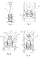
- FIGS. 1 to 4 show a first embodiment of an arrangement according to the invention, with the aid of an elongate support member 105 is to be attached to a ceiling.
- This support element 105 is, for example, an elongate support rail of a lighting system 100 to which luminaire modules or other units, in particular emitters, can also be attached.
- a plurality of the arrangements shown for suspension distributed to the support rail 105 are arranged.
- an elongate luminaire could also be fastened to a ceiling with the aid of the arrangement according to the invention.
- usually corresponding cable suspensions are provided at the two ends of the lamp.
- the first essential element of the arrangement generally designated by the reference numeral 1 is a flexible elongated suspension element formed by a cable 2 or cable.
- the cable 2 is fixed with its upper end to a ceiling mounting element 3, which in a manner not shown on the Ceiling is attached.
- the design of this ceiling fastening element 3 may be different and is not relevant to the present invention.
- the cable 2 is fixed to a fastening element 5.
- This fastener 5 is in the Figures 1 and 2 recognizable, in which the adjusting element discussed in more detail below is shown semi-transparent.
- the term "fixing” is to be understood below that the rope 2 is anchored or fixed to the fastener 5 so that it does not accidentally solve can not slide up.
- the fastening element 5 may be configured, for example, as in the aforementioned DE 103 41 550 A1 is described.
- a special clamping device within the fastener 5 extending through the fastener 5 rope 2 is fixed or clamped so that it can not slip out.
- this clamping device can be solved to allow a relative displacement between the cable 2 and fastener 5, whereby a height adjustment can be made.
- the present invention is by no means limited to such suspension systems.
- the fastening element 5 could also represent only an anchorage for the rope 2, which for this purpose has, for example, at its lower end a widening, which prevents slipping upwards. A height adjustment is then not possible in this case.
- the fastening element 5 is arranged on the upper side of a retaining clip 7, which engages with two lateral arms 8 in elongate recesses of the mounting rail 105.
- Other types of arrangement of the fastener 5 to the light or the lighting system 100 would be conceivable.
- fasteners 5 are arranged centrally on the support rail 105 and the lamp. Further, since the rope 2 is guided through the fastener 5 so that it protrudes from a central opening, the center of gravity of the suspension is in the region of the central longitudinal axis I (see FIG. 3 of the system). In the case of a symmetrical design of the luminaire or the light band system 100, this has the consequence that a symmetrical distribution of force exists and, accordingly, the luminaire or the system is currently suspended.
- an adjusting element is used according to the invention, the function of which will be explained in more detail below.
- FIGS. 1 to 4 is provided with the reference numeral 10 adjusting element formed as a sleeve.
- This sleeve 10 is placed from the top of the fastener 5, so it this - as in FIG. 1 represented - encompasses.
- the inner diameter of the sleeve-like adjusting element 10 is dimensioned such that there is a sufficient clearance to the fastening element 5. So it is no press or sliding seat required.
- this adjustment sleeve 10 is that an inclination of the object to be suspended is compensated by a deflection of the rope 2.
- the sleeve bottom 11 which faces away from the support rail 105, a hole 12 through which the cable 2 is guided.
- This hole 12 is off-center, preferably arranged as close to the edge region of the sleeve 10 and causes the rope 2 is deflected laterally.
- This deflection of the cable 2 has the consequence that now the point of application of the suspension is off-center or asymmetrical, whereby the asymmetric weight distribution of the lamp to be suspended or the lighting system 100 can be compensated. Ultimately, this leads to an inclination of the light or the lighting system 100 is prevented.
- the compensation of the asymmetrical weight distribution of the object to be suspended is thus achieved by a displacement of the point of application of the cable 2 away from the central or symmetrical axis I. It is possible, the adjustment 10 - as indicated by the double arrow in FIG. 4 shown - to rotate relative to the fastener 5 to compensate for different degrees of skew. The twisting has the consequence that the deviation of the position of the hole 12 from the central axis I can be changed.
- the rotation can be done both to the right side and to the left side to To compensate for inclinations in both directions.
- the frictional forces between the adjustment sleeve 10 and the fastening element 5, which are caused by the deflection and the weight of the system, in this case cause the adjustment sleeve 10 is then fixed in the appropriate position.
- the sleeve 10 could be locked in the appropriate position by additional measures, for example by the use of a clamping or fixing screw. This can ensure that the system remains permanently in the balanced position.
- the adjusting sleeve 10 is supported only indirectly on the fastening element 5, that is, for example, on the support rail 105 or the bracket 7 attacks.
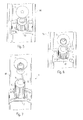
- FIGS. 5 to 8 A second embodiment of the adjusting element according to the invention is in the FIGS. 5 to 8 shown. Comparable elements are provided here with the same reference numerals.
- This second embodiment differs from the first embodiment primarily in the type of leadership of the rope 2.
- the adjusting element 10 has a lateral slot 13 in the sleeve edge.
- This slot 13 extends preferably over the entire height of the sleeve 10 to the sleeve bottom 11.
- the end of the slot 13 in this case in turn causes the deflection of the rope 2 shown in the figures.
- the degree of deflection of the rope 2 are changed in order to be able to flexibly balance asymmetrical weight distributions of the object to be suspended.
- An advantage of this second variant is that, due to the slit 13 extending over the entire height, it is possible to fit the adjusting sleeve 10 in the suspended state already when the luminaire is completely assembled. Unlike the variant of FIGS. 1 to 4 Thus, no need to thread and thread, so in a very simple and fast way to unexpectedly resulting inclinations of the system can be responded.
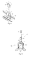
- FIG. 9 in this case shows a light band system 100, which is arranged by means of the inventive arrangement 1 on a - not shown ceiling - suspended.
- the light band system 100 essentially consists of an elongated support rail 105, on which the clamp 7 engages. Within the support rails 105 extend in the longitudinal directions conductor wires for electrical
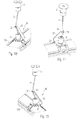
- FIGS. 10 to 12 A third inventive embodiment of an adjusting element is in the FIGS. 10 to 12 shown.
- the adjusting element 20 is formed as a C-shaped sheet metal part.
- From this lower leg 21 extends obliquely upward a second leg 22, at its upper end a short third leg 23 is formed.
- This third leg 23 has a lateral notch 24 through which the cable 2 is guided.
- the dimensions and arrangements of the legs 22 and 23 are such that the recess 24 is in turn offset from the center of the fastener 5 is arranged.
- the offset with respect to the axis of symmetry or the longitudinal axis of the system can then be changed by turning the adjusting element 20.
- the adjusting element 20 could be fixed in the appropriate position by additional measures.
- FIGS. 13 and 14 still a fourth embodiment.
- This is similar to the embodiment in the FIGS. 5 to 8 and is accordingly again designed as an attachable sleeve, which has a lateral slot 13.
- the upper end portion of the sleeve is formed in the form of an oblique cone.
- the adjusting element 10 there are no changes to the previously described embodiments. Again, therefore, by twisting the amount of deflection of the rope 2 can be varied. If necessary, the adjusting element could be locked in the appropriate position by means of a clamping or fixing screw.
- the sleeve-shaped adjusting elements can be made of different materials and manufactured in different ways. It would be conceivable, for example, the use of plastic, including the use of a transparent plastic material would be conceivable steel or aluminum. In the case of the use of plastic, the adjusting elements can be sprayed, for example, aluminum parts can be rotated, for example, or produced as extruded part.
- the solution of the invention opens up the possibility to compensate for inclinations in suspended lights or lighting systems in a simple manner.
- a particular advantage of the solution according to the invention consists in the fact that hitherto known suspension devices can be used and only in addition an adjusting element is used, with which the required correction is carried out.
Landscapes
- Engineering & Computer Science (AREA)
- General Engineering & Computer Science (AREA)
- Arrangement Of Elements, Cooling, Sealing, Or The Like Of Lighting Devices (AREA)
- Non-Portable Lighting Devices Or Systems Thereof (AREA)
- Clamps And Clips (AREA)
Abstract
Description
- Die vorliegende Erfindung betrifft eine Anordnung zur Befestigung eines vorzugsweise länglichen Gegenstandes an einem langgestreckten, flexiblen Aufhängungselement gemäß dem Oberbegriff des Anspruchs 1. Insbesondere betrifft die Erfindung eine Anordnung zur Befestigung einer Leuchte oder eines länglichen Trägerelements für eine Leuchte an einem Seil oder Kabel.
- Leuchten können hinsichtlich der Art und Weise ihrer Montage in unterschiedliche Kategorien eingeteilt werden. Neben so genannten Deckeneinbauleuchten und Deckenanbauleuchten, die versenkt in einer Decke oder bündig an der Unterseite einer Decke montiert werden, werden oftmals auch so genannte Pendelleuchten verwendet, die mit eine gewissen Abstand von der Decke oder einem Deckenelement angeordnet werden. Die Aufhängung derartiger Leuchten erfolgt dabei mittels langgestreckter flexibler Aufhängungselemente, beispielsweise mit Hilfe von Seilen oder Kabeln. Eine hierzu vorgesehene Befestigungsvorrichtung ist beispielsweise aus der
DE 103 41 550 A1 der Anmelderin bekannt. - Die zuvor beschriebene Seilaufhängung wird sowohl bei Einzelleuchten als auch bei länglichen Lichtbandsystemen verwendet, bei denen über mehrere Seile längliche Tragschienen an der Decke befestigt werden, wobei diese Tragschienen dann wiederum Trägerelemente darstellen, an denen Leuchteneinheiten befestigt werden können. Werden Befestigungsvorrichtungen verwendet, wie sie beispielsweise aus der oben genannten
DE 103 41 550 A1 bekannt sind, so kann ferner auch der Abstand zur Decke in flexibler Weise eingestellt werden. - In der Regel sind die Leuchten oder Lichtbandsysteme, welche mittels der Seile an der Decke befestigt werden, symmetrisch ausgeführt. Dies führt dazu, dass der Schwerpunkt der aufzuhängenden Elemente auch in der Mittelachse liegt und dementsprechend eine einfache Seilabhängung genügt. Es sind also lediglich an den Endbereichen der Leuchte bzw. in regelmäßigen Abständen der Tragschienen entsprechende Befestigungsvorrichtungen vorgesehen, welche mittig an der Leuchte bzw. dem Trägerelement angreifen.
- Da derartige Leuchten bzw. Lichtbänder sehr schmal ausgeführt werden, können allerdings schon geringe Ungenauigkeiten in der Gewichtsverteilung eine Schräglage hervorrufen. Es kommt dementsprechend mitunter vor, dass eine montierte Leuchte bzw. ein entsprechendes Lichtband trotz symmetrischer Ausführung leicht schräg bezüglich der Längs- bzw. Symmetrieachse hängt. Ferner können Lichtbänder durchaus auch mit asymmetrischem Zubehör bestückt werden. Beispielsweise Strahler, die an der Unterseite der Tragschiene angeordnet werden, weisen in der Regel eine asymmetrische Gewichtsverteilung auf und können ebenfalls eine Schräglage des Lichtbandes hervorrufen.
- Der vorliegenden Erfindung liegt nunmehr die Aufgabe zugrunde, derartige Probleme zu vermeiden. Dabei soll möglichst die bislang eingesetzte Seilabhängung erhalten bleiben und nur im Bedarfsfall mit einem möglichst geringen Aufwand eine Korrektur der Lage vorgenommen werden.
- Die Aufgabe wird durch eine Anordnung zur Befestigung eines Gegenstands mit den Merkmalen des Anspruchs 1 gelöst. Vorteilhafte Weiterbildungen der Erfindung sind Gegenstand der abhängigen Ansprüche.
- Die erfindungsgemäße Lösung beruht auf dem Gedanken, die bisherige Seilabhängung beizubehalten. Im Bedarfsfall kann die entsprechende Anordnung zur Befestigung der Leuchte oder des Lichtbands durch ein Justierelement ergänzt werden, welches eine Auslenkung des Aufhängungselements, also des Seils oder Kabels bewirkt und dementsprechend eine Korrektur ermöglicht.
- Erfindungsgemäß wird dementsprechend eine Anordnung zur Befestigung eines Gegenstands, beispielsweise einer Leuchte oder eines Trägerelements für eine Leuchte vorgeschlagen, wobei die Befestigung an einem langgestreckten, flexiblen Aufhängungselement, insbesondere an einem Seil oder Kabel erfolgt und wobei die Anordnung ein an dem zu befestigenden Gegenstand angeordnetes Befestigungselement aufweist, an dem ein Endbereich des Aufhängungselements fixiert ist. Erfindungsgemäß weist die Anordnung ferner ein Justierelement auf, welches sich einerseits an dem Befestigungselement - direkt oder indirekt - abstützt und andererseits eine Führung zur Auslenkung des Aufhängungselements bildet.
- Das erfindungsgemäße Justierelement stellt also ein Ergänzungselement dar, welches im Bedarfsfall der bekannten Seilaufhängung hinzugefügt werden kann, um entsprechende Korrekturen vorzunehmen. Die erfindungsgemäße Lösung ist dementsprechend in einfacher und schneller Weise realisierbar.
- Um die Justierung der Aufhängung individuell gestalten zu können, ist vorzugsweise vorgesehen, dass das Justierelement gegenüber dem Befestigungselement verstellbar, beispielsweise verdrehbar ist. Hierdurch kann das Maß der Auslenkung des Aufhängungselements verändert werden, um unterschiedlich starke Schrägstellungen ausgleichen zu können. Dabei kann ferner vorgesehen sein, dass das Justierelement dann in einer entsprechend geeigneten Position an dem Befestigungselement fixiert wird. Dies kann beispielsweise durch eine Klemm- oder Fixierschraube erfolgen.
- Das Befestigungselement ist in der Regel zylinderartig ausgebildet. In diesem Fall ist das Justierelement gemäß einem ersten bevorzugten Ausführungsbeispiel als Hülse ausgestaltet, welche dazu ausgebildet ist, auf das Befestigungselement aufgesetzt zu werden. Dabei kann das Justierelement in einem dem zu befestigenden Gegenstand abgewandten Hülsenboden ein außermittiges Loch aufweisen. Durch Verdrehung der Hülse gegenüber dem Befestigungselement kann die Auslenkung verändert werden, sodass eine nahezu stufenlose Einstellung des Justierelements ermöglicht ist.
- Bei einem zweiten Ausführungsbeispiel ist das Justierelement wiederum als Hülse ausgebildet und weist einen sich über die Seitenwand bis in einen dem zu befestigenden Gegenstand abgewandten Hülsenboden erstreckenden Schlitz auf. Wiederum kann durch Verdrehen der Hülse gegenüber dem Befestigungselement eine Einstellung der Justierung vorgenommen werden. Ferner besteht in diesem Fall sogar die Möglichkeit, das Justierelement bereits im montierten Zustand, also nachträglich anzubringen. Hierdurch wird die Möglichkeit eröffnet, in besonders einfacher Weise eine ungewünschte Schrägstellung der Leuchte oder des Lichtbandes zu kompensieren.
- In einer dritten Ausführungsform ist das Justierelement C-förmig ausgebildet. Ein Schenkel stützt sich hierbei an dem Befestigungselement ab, während hingegen der andere Schenkel die Führung für das Aufhängungselement bildet. Auch hier kann das Justierelement verdrehbar gegenüber dem Befestigungselement ausgebildet sein, um wiederum eine Einstellung der Justierung vorzunehmen.
- Wie bereits erwähnt besteht insbesondere die Möglichkeit, das erfindungsgemäße Justierelement bei standardmäßig verwendeten Befestigungselementen einzusetzen. Diese können beispielsweise entsprechend der
DE 103 41 550 A1 ausgestaltet sein, wobei sich hierbei das Aufhängungselement durch das hülsenartige Befestigungselement erstreckt. Innerhalb des Befestigungselements ist dann ein federnd gelagertes Verriegelungselement, beispielsweise eine Kugel oder dergleichen vorgesehen, über welche das Seil bzw. Kabel derart geklemmt wird, dass dieses an dem Befestigungselement sicher und effektiv fixiert wird. - Nachfolgend soll die Erfindung anhand der beiliegenden Zeichnung näher erläutert werden. Es zeigen:
- Figuren 1 bis 4
- Ansichten eines ersten Ausführungsbeispiels einer erfindungsgemäßen Anordnung zur Befestigung einer Leuchte an einem Seil;
- Figuren 5 bis 7
- Ansichten eines zweiten Ausführungsbeispiels;
- Figur 8
- das zweite Ausführungsbeispiel in Schnittdarstellung;
- Figur 9
- eine Schnittdarstellung eines mit Hilfe der erfindungsgemäßen Anordnung aufgehängten Lichtbandsystems;
- Figuren 10 bis 12
- Ansichten eines dritten Ausführungsbeispiels einer erfindungsgemäßen Anordnung und
- Figuren 13 und 14
- Ansichten eines vierten Ausführungsbeispiels einer erfindungsgemäßen Anordnung.
- Die
Figuren 1 bis 4 zeigen ein erstes Ausführungsbeispiel einer erfindungsgemäßen Anordnung, mit deren Hilfe ein längliches Trägerelement 105 an einer Decke befestigt werden soll. Bei diesem Trägerelement 105 handelt es sich beispielsweise um eine längliche Tragschiene eines Lichtbandsystems 100, an welche Leuchtenmodule oder andere Einheiten, insbesondere auch Strahler angesetzt werden können. In diesem Fall sind mehrere der dargestellten Anordnungen zur Aufhängung verteilt an der Tragschiene 105 angeordnet. In gleicher Weise könnte allerdings auch eine längliche Leuchte mit Hilfe der erfindungsgemäßen Anordnung an einer Decke befestigt werden. Hier sind dann üblicherweise an den beiden Enden der Leuchte entsprechende Seilaufhängungen vorgesehen. - Erstes wesentliches Element der allgemein mit dem Bezugszeichen 1 versehenen Anordnung ist ein flexibles langgestrecktes Aufhängungselement, welches durch ein Seil 2 oder Kabel gebildet wird. Das Seil 2 ist mit seinem oberen Ende an einem Deckenbefestigungselement 3 fixiert, welches in nicht näher dargestellter Weise an der Decke befestigt wird. Die Ausgestaltung dieses Deckenbefestigungselements 3 kann unterschiedlich sein und ist für die vorliegende Erfindung nicht weiter von Bedeutung.
- An einem unteren Endbereich ist das Seil 2 an einem Befestigungselement 5 fixiert. Dieses Befestigungselement 5 ist in den
Figuren 1 und 2 erkennbar, in denen das nachfolgend noch näher besprochene Justierelement halbtransparent dargestellt ist. Unter dem Begriff "Fixieren" ist nachfolgend zu verstehen, dass das Seil 2 an dem Befestigungselement 5 derart verankert bzw. befestigt ist, dass es sich nicht unbeabsichtigt lösen nicht nach oben rutschen kann. Hierfür kann das Befestigungselement 5 beispielsweise derart ausgestaltet sein, wie es in der zuvor genanntenDE 103 41 550 A1 beschrieben ist. Durch eine spezielle Klemmvorrichtung innerhalb des Befestigungselements 5 wird das sich durch das Befestigungselement 5 erstreckende Seil 2 derart fixiert bzw. verklemmt, dass es nicht herausrutschen kann. Diese Klemmvorrichtung kann allerdings gelöst werden, um eine Relativverschiebung zwischen Seil 2 und Befestigungselement 5 zu ermöglichen, wodurch eine Höhenanpassung vorgenommen werden kann. Die vorliegende Erfindung ist allerdings keinesfalls auf derartige Aufhängungssysteme beschränkt. In gleicher Weise könnte das Befestigungselement 5 auch lediglich eine Verankerung für das Seil 2 darstellen, welches hierzu beispielsweise an seinem unteren Ende eine Verbreiterung aufweist, die ein Durchrutschen nach oben verhindert. Eine Höhenanpassung ist in diesem Fall dann allerdings nicht möglich. - Das Befestigungselement 5 ist an der Oberseite einer Halteklammer 7 angeordnet, welche mit zwei seitlichen Armen 8 in längliche Ausnehmungen der Tragschiene 105 eingreift. Auch andere Arten der Anordnung des Befestigungselements 5 an der Leuchte bzw. dem Lichtbandsystem 100 wären denkbar.
- Standardmäßig sind derartige Befestigungselemente 5 mittig an der Tragschiene 105 bzw. der Leuchte angeordnet. Da ferner das Seil 2 derart durch das Befestigungselement 5 geführt ist, dass es aus einer zentralen Öffnung ragt, liegt der Schwerpunkt der Aufhängung im Bereich der mittigen Längsachse I (siehe
Figur 3 des Systems). Im Falle einer symmetrischen Ausgestaltung der Leuchte oder des Lichtbandsystems 100 hat dies zur Folge, dass eine symmetrische Kraftverteilung vorliegt und dementsprechend die Leuchte bzw. das System gerade aufgehängt ist. - Aufgrund von Abweichungen in der Gewichtsverteilung, die beispielsweise auf eine entsprechende Lagerung der innerhalb der Leuchte oder des Lichtbandsystems 100 verlaufenden Kabel zurückzuführen ist oder durch eine asymmetrische Anordnung der Lampenbetriebsgeräte hervorgerufen werden kann, kann es allerdings zu einer leichten Schrägstellung kommen. Hierbei ist dann die Leuchte bzw. das Lichtbandsystem 100 um die Achse I leicht verschwenkt, wobei eine derartige Schräglage selbstverständlich nicht erwünscht ist. Auch das Anordnen von Strahlern an der Tragschiene 100 kann zu einer asymmetrischen Gewichtsverteilung führen, welche die ungewünschte Schrägstellung hervorruft.
- Um eine derartige Neigung auszugleichen, wird erfindungsgemäß ein Justierelement eingesetzt, dessen Funktion nachfolgend näher erläutert wird.
- Bei dem Ausführungsbeispiel der
Figuren 1 bis 4 ist das mit dem Bezugszeichen 10 versehene Justierelement als Hülse ausgebildet. Diese Hülse 10 wird von der Oberseite her auf das Befestigungselement 5 aufgesetzt, sodass es dieses - wie inFigur 1 dargestellt - umgreift. Der Innendurchmesser des hülsenartigen Justierelements 10 ist dabei derart bemessen, dass ein ausreichendes Spiel zu dem Befestigungselement 5 besteht. Es ist also kein Press- oder Gleitsitz erforderlich. - Die Wirkung dieser Justierhülse 10 besteht darin, dass eine Schrägstellung des aufzuhängenden Objekts durch ein Auslenken des Seils 2 ausgeglichen wird. Im ersten Ausführungsbeispiel weist hierfür der Hülsenboden 11, welcher der Tragschiene 105 abgewandt ist, ein Loch 12 auf, durch welches das Seil 2 geführt ist. Dieses Loch 12 ist außermittig, vorzugsweise möglichst nahe am Randbereich der Hülse 10 angeordnet und führt dazu, dass das Seil 2 seitlich ausgelenkt wird. Diese Auslenkung des Seils 2 hat zur Folge, dass nunmehr der Angriffspunkt der Aufhängung außermittig bzw. asymmetrisch ist, wodurch die asymmetrische Gewichtsverteilung der aufzuhängenden Leuchte bzw. des Lichtbandsystems 100 ausgeglichen werden kann. Letztendlich führt dies dazu, dass eine Schrägstellung der Leuchte oder des Lichtbandsystems 100 verhindert wird.
- Die Kompensation der asymmetrischen Gewichtsverteilung des aufzuhängenden Objekts wird also durch eine Verlagerung des Angriffspunkts des Seils 2 von der Zentral- bzw. Symmetrieachse I weg erzielt. Dabei besteht die Möglichkeit, das Justierelement 10 - wie anhand des Doppelpfeils in
Figur 4 dargestellt - gegenüber dem Befestigungselement 5 zu verdrehen, um unterschiedlich stark ausgeprägte Schrägstellungen zu kompensieren. Das Verdrehen hat nämlich zur Folge, dass die Abweichung der Position des Lochs 12 von der zentralen Achse I verändert werden kann. Durch eine Verdrehung der Justierhülse 10 um 90° gegenüber dem Befestigungselement 5 kann also das Maß der Auslenkung des Seils 2 von einer neutralen Position in die Maximalauslenkung stufenlos verfahren werden, wobei die Verdrehung sowohl zur rechten Seite als auch zur linken Seite hin erfolgen kann, um Schrägstellungen in beiden Richtungen auszugleichen. Die Reibungskräfte zwischen Justierhülse 10 und dem Befestigungselement 5, die durch das Auslenken und das Gewicht des Systems entstehen, bewirken hierbei, dass die Justierhülse 10 dann in der entsprechenden Position fixiert wird. Optional könnte allerdings auch die Hülse 10 in der geeigneten Stellung durch zusätzliche Maßnahmen, beispielsweise durch die Verwendung einer Klemm- oder Fixierschraube arretiert werden. Hierdurch kann sichergestellt werden, dass das System dauerhaft in der austarierten Position verbleibt. Ferner wäre es auch denkbar, dass sich die Justierhülse 10 lediglich indirekt an dem Befestigungselement 5 abstützt, also beispielsweise an der Tragschiene 105 oder der Klammer 7 angreift. - Ein zweites Ausführungsbeispiel des erfindungsgemäßen Justierelements ist in den
Figuren 5 bis 8 dargestellt. Vergleichbare Elemente sind hierbei mit den gleichen Bezugszeichen versehen. - Dieses zweite Ausführungsbeispiel unterscheidet sich gegenüber dem ersten Ausführungsbeispiel in erster Linie in der Art der Führung des Seils 2. An Stelle eines Lochs im Hülsenboden weist nunmehr das Justierelement 10 einen seitlichen Schlitz 13 in der Hülsenrand auf. Dieser Schlitz 13 erstreckt sich dabei vorzugsweise über die gesamte Höhe der Hülse 10 bis zu dem Hülsenboden 11. Der Endbereich des Schlitzes 13 bewirkt hierbei wiederum die in den Figuren dargestellte Auslenkung des Seils 2. Wiederum kann also durch Verdrehen der Hülse 10 gegenüber dem Befestigungselement 5 das Maß der Auslenkung des Seils 2 verändert werden, um flexibel asymmetrische Gewichtsverteilungen des aufzuhängenden Objekts ausgleichen zu können.
- Ein Vorteil dieser zweiten Variante besteht darin, dass aufgrund des sich über die gesamte Höhe erstreckenden Schlitzes 13 die Möglichkeit besteht, die Justierhülse 10 bereits bei fertig montierter Leuchte im abgehängten Zustand aufzustecken. Im Gegensatz zu der Variante der
Figuren 1 bis 4 ist also kein Aus- und Einfädeln nötig, sodass in sehr einfacher und schneller Weise auf sich unerwartet ergebende Schrägstellungen des Systems reagiert werden kann. - Letztendlich kann dann beispielsweise eine Anordnung erreicht werden, wie sie in
Figur 9 dargestellt ist.Figur 9 zeigt hierbei ein Lichtbandsystem 100, welches mit Hilfe der erfindungsgemäßen Anordnung 1 an einer - nicht näher dargestellten Decke - abgehängt angeordnet ist. Das Lichtbandsystem 100 besteht im Wesentlichen aus einer länglichen Tragschiene 105, an der die Klammer 7 angreift. Innerhalb der Tragschienen 105 verlaufen in Längsrichtungen Leiteradern zur elektrischen - Stromversorgung von Leuchteneinsätzen sowie zur Übertragung von Steuerbefehlen. Dargestellt ist ferner ein Leuchteneinsatz 120, der von der Unterseite her an die Tragschiene angesetzt und an dieser arretiert wird. Im vorliegenden Fall ist dieser Leuchteneinsatz 120 symmetrisch zur Längsachse des Systems 100 ausgebildet. Trotz allem kann aufgrund einer außermittigen Verlegung der Kabel oder dergleichen eine asymmetrische Gewichtsverteilung vorliegen, die nunmehr in einfacher Weise durch das erfindungsgemäße Justierelement 10 ausgeglichen werden kann. Durch die Auslenkung des Seils 2 kann sichergestellt werden, dass der Angriffspunkt des Seils 2 oberhalb des Schwerpunkts des Lichtbandsystems 100 liegt, was zur Folge hat, dass dieses - wie dargestellt - ohne Schräglage aufgehängt werden kann.
- Ein drittes erfindungsgemäßes Ausführungsbeispiel eines Justierelements ist in den
Figuren 10 bis 12 gezeigt. In diesem Fall ist das Justierelement 20 als C-förmiges Blechteil ausgebildet. Der untere Schenkel 21, der geschlitzt ausgebildet ist, ermöglicht ein zentriertes Anlegen an dem Befestigungselement 5. Von diesem unteren Schenkel 21 erstreckt sich schräg nach oben ein zweiter Schenkel 22, an dessen oberen Ende ein kurzer dritter Schenkel 23 ausgebildet ist. Dieser dritte Schenkel 23 weist eine seitliche Einkerbung 24 auf, durch welche das Seil 2 geführt ist. Die Abmessungen und Anordnungen der Schenkel 22 und 23 sind dabei derart, dass die Ausnehmung 24 wiederum versetzt zum Zentrum des Befestigungselements 5 angeordnet ist. Auch hier kann dann durch ein Verdrehen des Justierelements 20 der Versatz gegenüber der Symmetrieachse bzw. Längsachse des Systems verändert werden. Wiederum könnten dann das Justierelement 20 in der entsprechenden Position durch zusätzliche Maßnahmen fixiert werden. - Schließlich zeigen die
Figuren 13 und 14 noch ein viertes Ausführungsbeispiel. Dieses ähnelt dem Ausführungsbeispiel in denFiguren 5 bis 8 und ist dementsprechend wiederum als aufsteckbare Hülse ausgebildet, welche einen seitlichen Schlitz 13 aufweist. Gegenüber dem Ausführungsbeispiel derFiguren 5 bis 8 ist nunmehr der obere Endbereich der Hülse in Form eines schrägen Kegels ausgebildet. Hinsichtlich der Funktion des Justierelements 10 ergeben sich allerdings keine Veränderungen zu den zuvor erläuterten Ausführungsbeispielen. Auch hier kann also durch Verdrehen wiederum das Maß der Auslenkung des Seils 2 variiert werden. Sofern erforderlich könnte mittels einer Klemm- oder Fixierschraube das Justierelement in der entsprechenden Position arretiert werden. - Die hülsenförmigen Justierelemente können aus unterschiedlichsten Materialien bestehen und in unterschiedlicher Weise hergestellt werden. Denkbar wäre beispielsweise die Verwendung von Kunststoff, wobei auch die Verwendung eines transparenten Kunststoffmaterials denkbar wäre, Stahl oder Aluminium. Im Falle der Verwendung von Kunststoff können die Justierelemente beispielsweise gespritzt werden, Aluminiumteile können beispielsweise gedreht oder als Fließpressteil hergestellt werden.
- Letztendlich eröffnet also die erfindungsgemäße Lösung die Möglichkeit, Schrägstellungen bei abgehängten Leuchten oder Lichtbandsystemen in einfacher Weise auszugleichen. Ein besonderer Vorteil der erfindungsgemäßen Lösung besteht hierbei darin, dass auf bislang bekannte Aufhängungsvorrichtungen zurückgegriffen werden kann und lediglich ergänzend ein Justierelement eingesetzt wird, mit dem die erforderliche Korrektur durchgeführt wird.
Claims (8)
- Anordnung (1) zur Befestigung eines Gegenstandes, beispielsweise einer Leuchte oder einem Trägerelement (105) für eine Leuchte, an einem langgestreckten, flexiblen Aufhängungselement (2), insbesondere an einem Seil oder Kabel, aufweisend ein an dem zu befestigenden Gegenstand angeordnetes Befestigungselement (5), an dem ein Endbereich des Aufhängungselements (2) fixiert ist,
dadurch gekennzeichnet,
dass die Anordnung (1) ferner ein Justierelement (10, 20) aufweist, welches sich einerseits an dem Befestigungselement (5) abstützt und andererseits eine Führung zur Auslenkung des Aufhängungselements (2) bildet. - Anordnung nach Anspruch 1,
dadurch gekennzeichnet,
dass das Justierelement (10, 20) gegenüber dem Befestigungselement (5) verstellbar, insbesondere verdrehbar ist. - Anordnung nach einem der vorherigen Ansprüche,
dadurch gekennzeichnet,
dass das Justierelement (10, 20) Mittel zum Fixieren an dem Befestigungselement (5) aufweist. - Anordnung nach Anspruch 3,
dadurch gekennzeichnet,
dass die Mittel zum Fixieren durch eine Klemm- oder Fixierschraube gebildet sind. - Anordnung nach einem der vorherigen Ansprüche,
dadurch gekennzeichnet,
dass das Befestigungselement (5) zylinderartig ausgebildet ist und das Justierelement (10, 20) als Hülse ausgestaltet ist, welche dazu ausgebildet ist, auf das Befestigungselement (5) aufgesetzt zu werden. - Anordnung nach Anspruch 5,
dadurch gekennzeichnet,
dass das Justierelement (10, 20) in einem dem zu befestigenden Gegenstand abgewandten Hülsenboden (11) ein außermittiges Loch (12) aufweist. - Anordnung nach Anspruch 5,
dadurch gekennzeichnet,
dass das Justierelement (10, 20) einen sich über die Seitenwand bis in einen dem zu befestigenden Gegenstand abgewandten Hülsenboden (11) erstreckenden Schlitz (13) aufweist. - Anordnung nach einem der Ansprüche 1 bis 5,
dadurch gekennzeichnet,
dass das Justierelement (10, 20) C-förmig ausgebildet ist, wobei ein Schenkel (21) sich an dem Befestigungselement (5) abstützt und ein weiterer Schenkel (23) die Führung für das Aufhängungselement (2) bildet.
Applications Claiming Priority (1)
| Application Number | Priority Date | Filing Date | Title |
|---|---|---|---|
| DE201010028332 DE102010028332A1 (de) | 2010-04-28 | 2010-04-28 | Anordnung zur Befestigung eines Gegenstandes an einem langgestreckten Aufhängungselement |
Publications (3)
| Publication Number | Publication Date |
|---|---|
| EP2383511A2 true EP2383511A2 (de) | 2011-11-02 |
| EP2383511A3 EP2383511A3 (de) | 2013-08-21 |
| EP2383511B1 EP2383511B1 (de) | 2014-09-17 |
Family
ID=44315120
Family Applications (1)
| Application Number | Title | Priority Date | Filing Date |
|---|---|---|---|
| EP20110164075 Active EP2383511B1 (de) | 2010-04-28 | 2011-04-28 | Anordnung zur Befestigung eines Gegenstandes an einem langgestreckten Aufhängungselement |
Country Status (2)
| Country | Link |
|---|---|
| EP (1) | EP2383511B1 (de) |
| DE (1) | DE102010028332A1 (de) |
Cited By (2)
| Publication number | Priority date | Publication date | Assignee | Title |
|---|---|---|---|---|
| WO2013144383A1 (es) * | 2012-03-27 | 2013-10-03 | Grupo T Diffusion, S.A. | Disposición para iluminación |
| AT14426U1 (de) * | 2014-10-07 | 2015-11-15 | Zumtobel Lighting Gmbh | Ausgleichsvorrichtung für eine Seilabhängung einer Leuchte |
Citations (1)
| Publication number | Priority date | Publication date | Assignee | Title |
|---|---|---|---|---|
| DE10341550A1 (de) | 2003-09-09 | 2005-03-31 | Zumtobel Staff Gmbh | Befestigungsvorrichtung zurlösbaren Befestigung eines Gegenstandes an einem langgestreckten Aufhängungselement |
Family Cites Families (11)
| Publication number | Priority date | Publication date | Assignee | Title |
|---|---|---|---|---|
| DE669399C (de) * | 1936-11-08 | 1938-12-23 | Schneider & Co Dr Ing | Litzenpendel mit mittels Klemmvorrichtung am Pendel in gewuenschter Hoehe aufhaengbarer Reflektorleuchte |
| US4306280A (en) * | 1978-11-06 | 1981-12-15 | Burke Peter Y | Multi-adjustable supporting device |
| US4351506A (en) * | 1981-03-02 | 1982-09-28 | Ohai Reynolds K | Loop for leveling a hanging lamp |
| FR2587089B1 (fr) * | 1985-09-10 | 1988-10-21 | Vianne Cristalleries Verreries | Monture a rattrapage de desequilibre pour suspensions |
| DE9102032U1 (de) * | 1991-02-21 | 1991-09-19 | Philips Patentverwaltung GmbH, 22335 Hamburg | Vorrichtung zum Befestigen eines Leuchtengehäuses |
| DE29612602U1 (de) * | 1996-07-20 | 1996-12-05 | Belitz, Rainer, 44623 Herne | Pendelleuchte |
| US7335836B2 (en) * | 2002-10-21 | 2008-02-26 | A.G.K., Ltd. | Power supply wire, wire grip, electric appliance suspending device, and electric appliance suspending method |
| DE202004014148U1 (de) * | 2004-09-09 | 2006-01-26 | Herner Glas Bernd Hoffbauer Gmbh & Co Leuchten Und Industrieglas Kg | Vorrichtung zur hängenden Anordnung |
| DE202005015148U1 (de) * | 2005-09-26 | 2006-02-09 | Seed Lighting Design Co., Ltd., Hsin Chuang | Verstellvorrichtung zur genauen Positionierung senkrecht hängender Gegenstände |
| CA2531464C (en) * | 2005-12-22 | 2009-11-03 | Eclairage Contraste | Assembly for vertically positioning a lamp-shade |
| EP2118560B1 (de) * | 2007-02-05 | 2013-05-01 | Louis Poulsen Lighting A/s | Anbringungseinrichtung |
-
2010
- 2010-04-28 DE DE201010028332 patent/DE102010028332A1/de not_active Withdrawn
-
2011
- 2011-04-28 EP EP20110164075 patent/EP2383511B1/de active Active
Patent Citations (1)
| Publication number | Priority date | Publication date | Assignee | Title |
|---|---|---|---|---|
| DE10341550A1 (de) | 2003-09-09 | 2005-03-31 | Zumtobel Staff Gmbh | Befestigungsvorrichtung zurlösbaren Befestigung eines Gegenstandes an einem langgestreckten Aufhängungselement |
Cited By (2)
| Publication number | Priority date | Publication date | Assignee | Title |
|---|---|---|---|---|
| WO2013144383A1 (es) * | 2012-03-27 | 2013-10-03 | Grupo T Diffusion, S.A. | Disposición para iluminación |
| AT14426U1 (de) * | 2014-10-07 | 2015-11-15 | Zumtobel Lighting Gmbh | Ausgleichsvorrichtung für eine Seilabhängung einer Leuchte |
Also Published As
| Publication number | Publication date |
|---|---|
| EP2383511A3 (de) | 2013-08-21 |
| EP2383511B1 (de) | 2014-09-17 |
| DE102010028332A1 (de) | 2011-12-01 |
Similar Documents
| Publication | Publication Date | Title |
|---|---|---|
| EP2576411B1 (de) | Vorrichtung zum aufhängen einer schiene, insbesondere einer schiene eines flurfreien förderers oder eines hebezeugs | |
| DE8611547U1 (de) | Trageinrichtung mit stufenlos verstellbaren Auslegern | |
| DE102012211438B4 (de) | Befestigungseinrichtung zum Befestigen von Zubehörteilen an medizinischen Einrichtungen | |
| EP1318741B1 (de) | Gardinenstange | |
| WO1995034719A1 (de) | Vorrichtung zum befestigen eines gestells an dem profil eines verlegten schienenprofilstrangs | |
| EP2383511B1 (de) | Anordnung zur Befestigung eines Gegenstandes an einem langgestreckten Aufhängungselement | |
| EP1076617A1 (de) | Träger- und befestigungsanordnung für fahrdrähte | |
| DE102004036328A1 (de) | Halterungsanordnung | |
| DE20021708U1 (de) | Fangvorrichtung für eine Aufhängeeinrichtung | |
| DE3214596C2 (de) | Aufhängebügel | |
| DE19507815C2 (de) | Halterung für Seile | |
| EP3120072B1 (de) | Mastbefestigung | |
| EP3650743B1 (de) | Befestigungsvorrichtung | |
| DE102018105970B4 (de) | Variable Deckenbefestigung | |
| DE102004063371B4 (de) | Conga-Ständer | |
| EP3217085B1 (de) | Leuchtenrahmen | |
| DE60226109T2 (de) | Aufhängefuss für eine Deckentragekonstruktion, Aufhängevorrichtung mit einem solchen Fuss und eine Deckentragekonstruktion und eine solche Aufhängevorrichtung umfassende Einheit | |
| DE29500981U1 (de) | Aufhängegarnitur | |
| DE29501156U1 (de) | Leuchtenanordnung | |
| EP1054415A2 (de) | Stabisolator | |
| DE202006002891U1 (de) | Deckenanordnung | |
| DE20308772U1 (de) | Halterung für Seile | |
| WO2000060281A1 (de) | Befestigungsvorrichtung zum befestigen eines gegenstandes an einer decke | |
| EP1736952A2 (de) | Trageprofilaufhängung sowie Anschlussstück dafür | |
| DE20214275U1 (de) | Modulfuß für die Sanitär-Installation, und Sanitär-Installation-Anordnung mit einem derartigen Modulfuß |
Legal Events
| Date | Code | Title | Description |
|---|---|---|---|
| AK | Designated contracting states |
Kind code of ref document: A2 Designated state(s): AL AT BE BG CH CY CZ DE DK EE ES FI FR GB GR HR HU IE IS IT LI LT LU LV MC MK MT NL NO PL PT RO RS SE SI SK SM TR |
|
| AX | Request for extension of the european patent |
Extension state: BA ME |
|
| PUAI | Public reference made under article 153(3) epc to a published international application that has entered the european phase |
Free format text: ORIGINAL CODE: 0009012 |
|
| PUAL | Search report despatched |
Free format text: ORIGINAL CODE: 0009013 |
|
| AK | Designated contracting states |
Kind code of ref document: A3 Designated state(s): AL AT BE BG CH CY CZ DE DK EE ES FI FR GB GR HR HU IE IS IT LI LT LU LV MC MK MT NL NO PL PT RO RS SE SI SK SM TR |
|
| AX | Request for extension of the european patent |
Extension state: BA ME |
|
| RIC1 | Information provided on ipc code assigned before grant |
Ipc: F21V 21/16 20060101ALI20130717BHEP Ipc: F21V 21/112 20060101AFI20130717BHEP |
|
| 17P | Request for examination filed |
Effective date: 20140205 |
|
| RBV | Designated contracting states (corrected) |
Designated state(s): AL AT BE BG CH CY CZ DE DK EE ES FI FR GB GR HR HU IE IS IT LI LT LU LV MC MK MT NL NO PL PT RO RS SE SI SK SM TR |
|
| GRAP | Despatch of communication of intention to grant a patent |
Free format text: ORIGINAL CODE: EPIDOSNIGR1 |
|
| INTG | Intention to grant announced |
Effective date: 20140328 |
|
| GRAP | Despatch of communication of intention to grant a patent |
Free format text: ORIGINAL CODE: EPIDOSNIGR1 |
|
| INTG | Intention to grant announced |
Effective date: 20140509 |
|
| GRAS | Grant fee paid |
Free format text: ORIGINAL CODE: EPIDOSNIGR3 |
|
| GRAA | (expected) grant |
Free format text: ORIGINAL CODE: 0009210 |
|
| AK | Designated contracting states |
Kind code of ref document: B1 Designated state(s): AL AT BE BG CH CY CZ DE DK EE ES FI FR GB GR HR HU IE IS IT LI LT LU LV MC MK MT NL NO PL PT RO RS SE SI SK SM TR |
|
| REG | Reference to a national code |
Ref country code: GB Ref legal event code: FG4D Free format text: NOT ENGLISH |
|
| REG | Reference to a national code |
Ref country code: CH Ref legal event code: EP Ref country code: CH Ref legal event code: NV Representative=s name: FIAMMENGHI-FIAMMENGHI, CH |
|
| REG | Reference to a national code |
Ref country code: IE Ref legal event code: FG4D Free format text: LANGUAGE OF EP DOCUMENT: GERMAN |
|
| REG | Reference to a national code |
Ref country code: AT Ref legal event code: REF Ref document number: 687883 Country of ref document: AT Kind code of ref document: T Effective date: 20141015 |
|
| REG | Reference to a national code |
Ref country code: DE Ref legal event code: R096 Ref document number: 502011004384 Country of ref document: DE Effective date: 20141106 |
|
| PG25 | Lapsed in a contracting state [announced via postgrant information from national office to epo] |
Ref country code: FI Free format text: LAPSE BECAUSE OF FAILURE TO SUBMIT A TRANSLATION OF THE DESCRIPTION OR TO PAY THE FEE WITHIN THE PRESCRIBED TIME-LIMIT Effective date: 20140917 Ref country code: GR Free format text: LAPSE BECAUSE OF FAILURE TO SUBMIT A TRANSLATION OF THE DESCRIPTION OR TO PAY THE FEE WITHIN THE PRESCRIBED TIME-LIMIT Effective date: 20141218 Ref country code: LT Free format text: LAPSE BECAUSE OF FAILURE TO SUBMIT A TRANSLATION OF THE DESCRIPTION OR TO PAY THE FEE WITHIN THE PRESCRIBED TIME-LIMIT Effective date: 20140917 Ref country code: NO Free format text: LAPSE BECAUSE OF FAILURE TO SUBMIT A TRANSLATION OF THE DESCRIPTION OR TO PAY THE FEE WITHIN THE PRESCRIBED TIME-LIMIT Effective date: 20141217 Ref country code: SE Free format text: LAPSE BECAUSE OF FAILURE TO SUBMIT A TRANSLATION OF THE DESCRIPTION OR TO PAY THE FEE WITHIN THE PRESCRIBED TIME-LIMIT Effective date: 20140917 |
|
| REG | Reference to a national code |
Ref country code: NL Ref legal event code: VDEP Effective date: 20140917 |
|
| REG | Reference to a national code |
Ref country code: LT Ref legal event code: MG4D |
|
| PG25 | Lapsed in a contracting state [announced via postgrant information from national office to epo] |
Ref country code: RS Free format text: LAPSE BECAUSE OF FAILURE TO SUBMIT A TRANSLATION OF THE DESCRIPTION OR TO PAY THE FEE WITHIN THE PRESCRIBED TIME-LIMIT Effective date: 20140917 Ref country code: LV Free format text: LAPSE BECAUSE OF FAILURE TO SUBMIT A TRANSLATION OF THE DESCRIPTION OR TO PAY THE FEE WITHIN THE PRESCRIBED TIME-LIMIT Effective date: 20140917 Ref country code: CY Free format text: LAPSE BECAUSE OF FAILURE TO SUBMIT A TRANSLATION OF THE DESCRIPTION OR TO PAY THE FEE WITHIN THE PRESCRIBED TIME-LIMIT Effective date: 20140917 Ref country code: HR Free format text: LAPSE BECAUSE OF FAILURE TO SUBMIT A TRANSLATION OF THE DESCRIPTION OR TO PAY THE FEE WITHIN THE PRESCRIBED TIME-LIMIT Effective date: 20140917 |
|
| PG25 | Lapsed in a contracting state [announced via postgrant information from national office to epo] |
Ref country code: NL Free format text: LAPSE BECAUSE OF FAILURE TO SUBMIT A TRANSLATION OF THE DESCRIPTION OR TO PAY THE FEE WITHIN THE PRESCRIBED TIME-LIMIT Effective date: 20140917 |
|
| PG25 | Lapsed in a contracting state [announced via postgrant information from national office to epo] |
Ref country code: ES Free format text: LAPSE BECAUSE OF FAILURE TO SUBMIT A TRANSLATION OF THE DESCRIPTION OR TO PAY THE FEE WITHIN THE PRESCRIBED TIME-LIMIT Effective date: 20140917 Ref country code: PT Free format text: LAPSE BECAUSE OF FAILURE TO SUBMIT A TRANSLATION OF THE DESCRIPTION OR TO PAY THE FEE WITHIN THE PRESCRIBED TIME-LIMIT Effective date: 20150119 Ref country code: SK Free format text: LAPSE BECAUSE OF FAILURE TO SUBMIT A TRANSLATION OF THE DESCRIPTION OR TO PAY THE FEE WITHIN THE PRESCRIBED TIME-LIMIT Effective date: 20140917 Ref country code: EE Free format text: LAPSE BECAUSE OF FAILURE TO SUBMIT A TRANSLATION OF THE DESCRIPTION OR TO PAY THE FEE WITHIN THE PRESCRIBED TIME-LIMIT Effective date: 20140917 Ref country code: RO Free format text: LAPSE BECAUSE OF FAILURE TO SUBMIT A TRANSLATION OF THE DESCRIPTION OR TO PAY THE FEE WITHIN THE PRESCRIBED TIME-LIMIT Effective date: 20140917 Ref country code: CZ Free format text: LAPSE BECAUSE OF FAILURE TO SUBMIT A TRANSLATION OF THE DESCRIPTION OR TO PAY THE FEE WITHIN THE PRESCRIBED TIME-LIMIT Effective date: 20140917 Ref country code: IS Free format text: LAPSE BECAUSE OF FAILURE TO SUBMIT A TRANSLATION OF THE DESCRIPTION OR TO PAY THE FEE WITHIN THE PRESCRIBED TIME-LIMIT Effective date: 20150117 |
|
| PG25 | Lapsed in a contracting state [announced via postgrant information from national office to epo] |
Ref country code: PL Free format text: LAPSE BECAUSE OF FAILURE TO SUBMIT A TRANSLATION OF THE DESCRIPTION OR TO PAY THE FEE WITHIN THE PRESCRIBED TIME-LIMIT Effective date: 20140917 |
|
| REG | Reference to a national code |
Ref country code: DE Ref legal event code: R097 Ref document number: 502011004384 Country of ref document: DE |
|
| PLBE | No opposition filed within time limit |
Free format text: ORIGINAL CODE: 0009261 |
|
| STAA | Information on the status of an ep patent application or granted ep patent |
Free format text: STATUS: NO OPPOSITION FILED WITHIN TIME LIMIT |
|
| PG25 | Lapsed in a contracting state [announced via postgrant information from national office to epo] |
Ref country code: DK Free format text: LAPSE BECAUSE OF FAILURE TO SUBMIT A TRANSLATION OF THE DESCRIPTION OR TO PAY THE FEE WITHIN THE PRESCRIBED TIME-LIMIT Effective date: 20140917 |
|
| 26N | No opposition filed |
Effective date: 20150618 |
|
| PG25 | Lapsed in a contracting state [announced via postgrant information from national office to epo] |
Ref country code: IT Free format text: LAPSE BECAUSE OF FAILURE TO SUBMIT A TRANSLATION OF THE DESCRIPTION OR TO PAY THE FEE WITHIN THE PRESCRIBED TIME-LIMIT Effective date: 20140917 |
|
| PG25 | Lapsed in a contracting state [announced via postgrant information from national office to epo] |
Ref country code: SI Free format text: LAPSE BECAUSE OF FAILURE TO SUBMIT A TRANSLATION OF THE DESCRIPTION OR TO PAY THE FEE WITHIN THE PRESCRIBED TIME-LIMIT Effective date: 20140917 Ref country code: LU Free format text: LAPSE BECAUSE OF FAILURE TO SUBMIT A TRANSLATION OF THE DESCRIPTION OR TO PAY THE FEE WITHIN THE PRESCRIBED TIME-LIMIT Effective date: 20150428 Ref country code: MC Free format text: LAPSE BECAUSE OF FAILURE TO SUBMIT A TRANSLATION OF THE DESCRIPTION OR TO PAY THE FEE WITHIN THE PRESCRIBED TIME-LIMIT Effective date: 20140917 |
|
| REG | Reference to a national code |
Ref country code: IE Ref legal event code: MM4A |
|
| REG | Reference to a national code |
Ref country code: FR Ref legal event code: PLFP Year of fee payment: 6 |
|
| PG25 | Lapsed in a contracting state [announced via postgrant information from national office to epo] |
Ref country code: IE Free format text: LAPSE BECAUSE OF NON-PAYMENT OF DUE FEES Effective date: 20150428 |
|
| PG25 | Lapsed in a contracting state [announced via postgrant information from national office to epo] |
Ref country code: MT Free format text: LAPSE BECAUSE OF FAILURE TO SUBMIT A TRANSLATION OF THE DESCRIPTION OR TO PAY THE FEE WITHIN THE PRESCRIBED TIME-LIMIT Effective date: 20140917 |
|
| REG | Reference to a national code |
Ref country code: FR Ref legal event code: PLFP Year of fee payment: 7 |
|
| PG25 | Lapsed in a contracting state [announced via postgrant information from national office to epo] |
Ref country code: SM Free format text: LAPSE BECAUSE OF FAILURE TO SUBMIT A TRANSLATION OF THE DESCRIPTION OR TO PAY THE FEE WITHIN THE PRESCRIBED TIME-LIMIT Effective date: 20140917 Ref country code: BG Free format text: LAPSE BECAUSE OF FAILURE TO SUBMIT A TRANSLATION OF THE DESCRIPTION OR TO PAY THE FEE WITHIN THE PRESCRIBED TIME-LIMIT Effective date: 20140917 Ref country code: HU Free format text: LAPSE BECAUSE OF FAILURE TO SUBMIT A TRANSLATION OF THE DESCRIPTION OR TO PAY THE FEE WITHIN THE PRESCRIBED TIME-LIMIT; INVALID AB INITIO Effective date: 20110428 |
|
| PG25 | Lapsed in a contracting state [announced via postgrant information from national office to epo] |
Ref country code: BE Free format text: LAPSE BECAUSE OF NON-PAYMENT OF DUE FEES Effective date: 20150430 |
|
| PG25 | Lapsed in a contracting state [announced via postgrant information from national office to epo] |
Ref country code: TR Free format text: LAPSE BECAUSE OF FAILURE TO SUBMIT A TRANSLATION OF THE DESCRIPTION OR TO PAY THE FEE WITHIN THE PRESCRIBED TIME-LIMIT Effective date: 20140917 |
|
| REG | Reference to a national code |
Ref country code: FR Ref legal event code: PLFP Year of fee payment: 8 |
|
| PG25 | Lapsed in a contracting state [announced via postgrant information from national office to epo] |
Ref country code: MK Free format text: LAPSE BECAUSE OF FAILURE TO SUBMIT A TRANSLATION OF THE DESCRIPTION OR TO PAY THE FEE WITHIN THE PRESCRIBED TIME-LIMIT Effective date: 20140917 |
|
| PG25 | Lapsed in a contracting state [announced via postgrant information from national office to epo] |
Ref country code: AL Free format text: LAPSE BECAUSE OF FAILURE TO SUBMIT A TRANSLATION OF THE DESCRIPTION OR TO PAY THE FEE WITHIN THE PRESCRIBED TIME-LIMIT Effective date: 20140917 |
|
| REG | Reference to a national code |
Ref country code: DE Ref legal event code: R084 Ref document number: 502011004384 Country of ref document: DE |
|
| PGFP | Annual fee paid to national office [announced via postgrant information from national office to epo] |
Ref country code: CH Payment date: 20200424 Year of fee payment: 10 Ref country code: FR Payment date: 20200429 Year of fee payment: 10 |
|
| PGFP | Annual fee paid to national office [announced via postgrant information from national office to epo] |
Ref country code: AT Payment date: 20200420 Year of fee payment: 10 |
|
| REG | Reference to a national code |
Ref country code: AT Ref legal event code: MM01 Ref document number: 687883 Country of ref document: AT Kind code of ref document: T Effective date: 20210428 |
|
| PG25 | Lapsed in a contracting state [announced via postgrant information from national office to epo] |
Ref country code: FR Free format text: LAPSE BECAUSE OF NON-PAYMENT OF DUE FEES Effective date: 20210430 Ref country code: CH Free format text: LAPSE BECAUSE OF NON-PAYMENT OF DUE FEES Effective date: 20210430 Ref country code: AT Free format text: LAPSE BECAUSE OF NON-PAYMENT OF DUE FEES Effective date: 20210428 Ref country code: LI Free format text: LAPSE BECAUSE OF NON-PAYMENT OF DUE FEES Effective date: 20210430 |
|
| PGFP | Annual fee paid to national office [announced via postgrant information from national office to epo] |
Ref country code: GB Payment date: 20220419 Year of fee payment: 12 |
|
| P01 | Opt-out of the competence of the unified patent court (upc) registered |
Effective date: 20230530 |
|
| GBPC | Gb: european patent ceased through non-payment of renewal fee |
Effective date: 20230428 |
|
| PG25 | Lapsed in a contracting state [announced via postgrant information from national office to epo] |
Ref country code: GB Free format text: LAPSE BECAUSE OF NON-PAYMENT OF DUE FEES Effective date: 20230428 |
|
| PG25 | Lapsed in a contracting state [announced via postgrant information from national office to epo] |
Ref country code: GB Free format text: LAPSE BECAUSE OF NON-PAYMENT OF DUE FEES Effective date: 20230428 |
|
| PGFP | Annual fee paid to national office [announced via postgrant information from national office to epo] |
Ref country code: DE Payment date: 20250428 Year of fee payment: 15 |