EP2383199B1 - Dispositif de fermeture pour récipient et élément d'étanchéité pour le dispositif - Google Patents
Dispositif de fermeture pour récipient et élément d'étanchéité pour le dispositif Download PDFInfo
- Publication number
- EP2383199B1 EP2383199B1 EP20110003090 EP11003090A EP2383199B1 EP 2383199 B1 EP2383199 B1 EP 2383199B1 EP 20110003090 EP20110003090 EP 20110003090 EP 11003090 A EP11003090 A EP 11003090A EP 2383199 B1 EP2383199 B1 EP 2383199B1
- Authority
- EP
- European Patent Office
- Prior art keywords
- flange
- seal member
- projection
- closure device
- compressible
- Prior art date
- Legal status (The legal status is an assumption and is not a legal conclusion. Google has not performed a legal analysis and makes no representation as to the accuracy of the status listed.)
- Active
Links
Images


Classifications
-
- B—PERFORMING OPERATIONS; TRANSPORTING
- B65—CONVEYING; PACKING; STORING; HANDLING THIN OR FILAMENTARY MATERIAL
- B65D—CONTAINERS FOR STORAGE OR TRANSPORT OF ARTICLES OR MATERIALS, e.g. BAGS, BARRELS, BOTTLES, BOXES, CANS, CARTONS, CRATES, DRUMS, JARS, TANKS, HOPPERS, FORWARDING CONTAINERS; ACCESSORIES, CLOSURES, OR FITTINGS THEREFOR; PACKAGING ELEMENTS; PACKAGES
- B65D51/00—Closures not otherwise provided for
- B65D51/002—Closures to be pierced by an extracting-device for the contents and fixed on the container by separate retaining means
Definitions
- the present invention relates to a closure device for sealing the opening of a container such as a vial, and to a seal member for the device.
- a cylindrical vial having a closed bottom is used to contain medicines, various test reagents, or the like.
- the vial has an opening which opens at the top and through which the content is put in and taken out.
- a rim is formed around the opening.
- the opening is conventionally sealed with a closure device that comprises, for example, an aluminum protector and a seal member.
- the protector has a wear part on the upper surface, and to the wear part a synthetic resin cap is affixed.
- the seal member fits into the inner surface of the protector and seals the opening.
- a medicament contained in the vial is lyophilized as follows.
- the seal member is attached to the vial in a state in which a flange of the seal member is not in contact with the opening (hereafter referred to as an "incompletely sealing state"), and the vial is placed in a lyophilization apparatus.
- the incompletely sealing state the seal member does not seal the opening, and the inside of the vial containing the medicament communicates with the outside via the opening.
- liquid components in the medicament are frozen and then sublimated to be removed from the vial.
- the seal member is pushed down so as to seal the opening (hereinafter this state is referred to as a "sealing state").
- the sealed vial is taken out from the lyophilization apparatus, and the skirt of the protector is wound on the seal member with the use of a winding apparatus.
- the vial having the aluminum protector is made of, as constituents, four kinds of materials, which are glass, aluminum, synthetic resin, and rubber. These materials are difficult to separate during disposal.
- the vial taken out from a lyophilization apparatus is sealed with the seal member, whose leg has been inserted into the opening, the sealing performance is imperfect.
- a closure device for a container comprising a synthetic resin cap provided with a cylinder part and with a top wall, and a seal member that is to be attached to the cap (see, for example, JP-07-165252-A ).
- the top wall has a window for needle entry, and the cylinder part hangs down from the outer circumference of the top wall.
- a locking means is disposed on the inner surface of the cylinder part.
- the seal member fits into the inside of the cap.
- the seal member comprises a disk-shaped flange and a cylindrical leg hanging down from the under surface of the flange.
- the vial is placed in a lyophilization apparatus with its opening provided with the closure device in the incompletely sealing state. After the completion of the lyophilization, the vial is pressed down so that the closure device is pushed down to the sealing state. In this sealing state, the flange is firmly pressed against the periphery of the vial opening by the top wall of the cap.
- the locking means locks at the under surface of the rim of the vial, thereby holding the cap in a state in which the seal member is firmly pressed against the upper surface of the rim by the top wall.
- Transition from the incompletely sealing state to the sealing state is achieved as follows: for example, in the lyophilization apparatus, the gaps between the shelves are narrowed, and the upper shelf presses down the vial so as to push down the closure device.
- the pressing force is set at, for example, 60 N or less.
- size variations occur in, for example, the overall height of the vial, the thickness of the flange, the horizontal level of the shelves of the lyophilization apparatus, the gaps between the multiple shelves, or the like.
- the size tolerance of, for example, the thickness of the flange is set at ⁇ 0.3 mm.
- the size tolerance of the overall height of the vial is set at as large as ⁇ 0.5 mm. Consequently, it is difficult to securely cap a large number of (for example, 6000) vials at a time without failures by pushing down their closure devices to the sealing state by means of the shelves that move a certain distance.
- the top wall of the cap may fail to firmly press down the seal member, which may result in sealing failures or decrease in airtightness.
- the flange may not be sufficiently pushed down by the cap, which may result in sealing failure.
- the size of the projection and/or the thickness of the flange is larger, the pressing force required for capping is excessively high and thus it is difficult to securely cap all the vials with the seal members.
- the content of the vial is taken out according to the following process. First, from the window for needle entry located in the center of the top wall, an injection needle is inserted into the vial through the center part of the upper surface of the seal member. Next, a dissolving solution or the like is injected into the vial through the needle, and the dissolved content is pumped out with the needle. Unless the flange is firmly pressed against the upper surface of the rim by the cap, the insertion force causes the center part of the seal member to be deformed toward the inside of the vial and, as a result, the insertion may fail.
- EP 1 004 287 A1 and US 5 316 163 A disclose seal members and caps for sealing a container.
- the present invention provides a closure device as defined in claim 1, for example, as shown in Figs. 1 to 17B , which show embodiments of the invention.
- the present invention also comprises a seal member having the following structure.
- the seal member is used for the closure device 1.
- the seal member comprises a disk-shaped flange 10 and a leg 11 that hangs down from the under surface of the flange 10.
- the seal member also comprises a compressible projection 29 that projects upward from the upper surface of the flange 10.
- the compressible projection 29 is annularly arranged in contact with and along the outer circumference of the flange 10 in a planar view.
- the present invention exerts the following functions and effects.
- Pushing down the closure device causes the top wall to push down the seal member, and then the leg of the seal member is fully inserted into the container.
- the flange is pressed against the upper surface around the opening of a container by the top wall.
- the closure device in the incompletely sealing state is pushed down, first the top wall presses down the compressible projection, and then presses down part of the flange just under the compressible projection. After the compressible projection is flattened, the top wall presses down the other part of the flange. That is, via the compressible projection that is pressed and thereby compressed, the flange just under the compressible projection is pressed against the upper surface of the rim around the opening of the container.
- the compressible projection is annularly arranged along the outer circumference of the flange, the downward pressing force through the compressible projection presses part of the flange just under the compressible projection against the upper surface of the rim and, as a result, the opening is sealed.
- the opening of the container is securely sealed by the seal member; thus the inside of the container is completely shut off from the outside and is free from biological contamination, and the liquid tightness and airtightness of the container are maintained.
- the compressible projection is in contact with the outer circumference of the flange in a planar view and thus the flange's upper surface surrounded by the outer circumference of the compressible projection is most extensive.
- the vial is capped by means of the shelf of a lyophilization apparatus or the like, the pressing force through the top wall received by the compressible projection is evenly distributed to the extensive surface.
- This structure enables the top wall to uniformly press down the flange, and consequently the upper surface of the seal member is stably kept horizontal.
- the seal member is set onto the opening of the vial in a proper state.
- the height of the lateral surface of the flange is increased in the vertical direction by the height of the compressible projection formed on the outer circumference of the flange.
- the receiving projection receives the compressible projection and prevents the flange from moving radially inward. Consequently, even when atmospheric pressure acts on the center of the seal member, this structure prevents the edge of the flange from moving or becoming thinner, decreases sealing failures, and improves the airtightness.
- the flange In the sealing state, the flange is pressed against the upper surface around the opening by the top wall, and the receiving projection bites into the upper surface of the flange. Only the receiving projection is provided on the under surface of the cap, yet this simple structure is sufficient to prevent the flange from moving radially inward and to firmly hold the flange between the top wall of the cap and the upper surface of the container.
- the above structure also prevents the seal member from being deformed toward the inside of the container by the insertion force of an injection needle or the like that is inserted through the center of the seal member in order to take out the content of the container. Even when the tip of the injection needle accidentally sticks into the leg of the seal member, the flange is prevented from being drawn into the container along with the leg. Thus the structure ensures insertion of the injection needle or the like into the container through the seal member.
- the present invention also comprises the following closure device for a container.
- the compressible projection 29 is formed into a discontinuous annular ring that is arranged along the outer circumference of the flange 10.
- the space surrounded by the compressible projection communicates with the outside via discontinuous parts.
- the present invention also comprises the following closure device for a container.
- a plurality of the compressible projections 29 are arranged along the outer circumference of the flange 10, and each of the compressible projections extends radially inward from the outer circumference of the flange 10.
- the flange 10 under the compressible projections 29 is extensively pressed against the rim around the opening. Consequently, the opening is more securely sealed by the seal member.
- the present invention also comprises the following closure device for a container.
- the receiving projection 27 is an annular ring that surrounds the opening 6 in a planar view. This embodiment ensures that the receiving projection receives the compressible projection throughout the whole circumference of the opening.
- the annular ring that surrounds the opening may be discontinuous in the circumference direction.
- the receiving projection is more preferably a continuous annular ring that is arranged along the circumference because the continuous annular ring can more effectively prevent the flange from moving radially inward.
- the present invention also comprises the following closure device for a container.
- the height h of the compressible projection 29 is 10 to 60% of the thickness t of the flange 10 excluding the compressible projection 29.
- the compression of the compressible projection effectively absorbs each size variation occurring within the tolerance, and therefore a small pressing force is sufficient to ensure sealing of the opening with the seal member.
- the height of the compressible projection is more preferably 20 to 50% of the thickness of the flange.
- the present invention also comprises the following closure device for a container.
- the lower edge of the receiving projection 27 has an angle of 90 degrees or less.
- the receiving projection is intended to reliably bite into the upper surface of the flange.
- the angle of the lower edge is preferably set at 70 degrees or less. If the sectional shape of the lower edge is excessively sharp, the lower edge may damage the surface of the seal member and/or the strength of the receiving projection may decrease. Accordingly, the angle of the lower edge is more preferably set at 20 to 65 degrees.
- the lower edge is preferably chamfered into, for example, a rounded shape having a radius of about 0.05 mm.
- the present invention also comprises the following closure device for a container.
- the receiving projection 27 in a vertical section that passes through the center axis of the opening 6, the receiving projection 27 has a sharp angle ⁇ of 45 degrees or less between the surface facing radially outward and the vertical line.
- the receiving projection reliably receives the flange against the insertion force of an injection needle or the like, thereby preventing the center part of the flange from being deformed toward the inside of a container.
- the sharp angle more preferably has an angle of about zero degrees, i.e. , the surface facing radially outward of the receiving projection 27 more preferably stands vertically.
- the present invention also comprises the following closure device for a container.
- the height L of the receiving projection 27 is 0.3 to 2.0 mm.
- the receiving projection having a height of 0.3 mm or more reliably receives the flange against the insertion force of an injection needle or the like , thereby preventing the center part of the flange from being deformed toward the inside of a container.
- the receiving projection having a height of 2.0 mm or less would damage the surface of the seal member.
- the present invention also comprises the following closure device for a container.
- the seal member 8 is made of at least one of a synthetic rubber material and a thermoplastic elastomer. This embodiment enables the production of the seal member having excellent seal performance with stable quality.
- the content of the container is not limited to a particular thing, and the content may be, for example, a powder preparation, a liquid preparation, or the like. However, the content is preferably a lyophilized preparation because the closure device has an advantage of, in the incompletely sealing state, being easily pushed down to the sealing state in a lyophilization apparatus.
- Figs. 1 to 8 show embodiments of the present invention.
- Fig. 1 is a vertical sectional view of a vial 2 (a container) to which the closure device 1 is attached in the incompletely sealing state Y.
- the vial 2 comprises a cylindrical trunk 3 with a bottom, and the trunk 3 has a storage part 4.
- the storage part 4 can contain contents such as a medicine.
- the upper part of the trunk 3 extends to a neck 5.
- the top of the neck 5 has an opening 6.
- the periphery of the opening 6 is formed into a rim 7 that swells radially outward.
- the closure device 1 comprises a seal member 8 and a cap 9.
- the seal member 8 is to cover the opening 6 and made of a synthetic rubber having rubber elasticity, for example, a butyl rubber.
- the cap 9 is to cover the seal member 8 and made of a synthetic resin.
- the seal member 8 comprises a flange 10 and a leg 11.
- the flange 10 is shaped like a disk and is to be mounted on the upper surface of the rim 7.
- the leg 11 is shaped like a cylinder that hangs down from the radially intermediate part of the under surface of the flange 10.
- the leg 11 has a notch 12 extending from the bottom of the leg 11 to the middle part of the seal member in the vertical direction.
- the top of the notch 12 is to be positioned above the opening 6 in the incompletely sealing state Y as shown in Fig. 1 .
- the inside of the storage part 4 communicates with the outside of the vial 2 via the opening 6 and the notch 12.
- the outer diameter of the leg 11 is slightly larger than the inner diameter of the opening 6 and thus, when the leg 11 is inserted into the opening 6, the leg 11 is slightly compressed.
- the cap 9 comprises a cap body 13 and a lid 14 that is fixed on the top of the cap body 13.
- the cap body 13 comprises a top wall 15, a cylinder part 16, and an annular locking member 17.
- the top wall 15 is to be disposed above the flange 10.
- the cylinder part 16 hangs down from the outer circumference of the top wall 15.
- the locking member 17 is attached to the inner surface of the cylinder part 16.
- On the top of the locking member 17, a locking part 18 is formed.
- a window for needle entry 19 opens. From the center of the under surface of the lid 14, a cylindrical sealer 20 hangs down, passing through the window for needle entry 19.
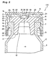
- the vial is pressed down from the above so that the closure device 1 is pushed down to the sealing state X as shown in Fig. 2 .
- the sealing state X the flange 10 is firmly pressed against the upper surface around the opening 6 by the top wall 15, and thereby the opening 6 is sealed.
- the locking part 18 locks at the under surface of the rim 7 of the vial 2, thereby holding the cap 9 in the sealing state X.
- the bottom of the sealer 20 bites into the upper surface of the seal member 8, and consequently the space above the center of the upper surface of the seal member 8 is airtightly shut off from the outside.
- the cap body 13 On the upper surface of the cap body 13 formed are two depressions 21 as gates for injection molding, and an annular groove 22 surrounding the window for needle entry 19. On the under surface of the lid 14, four joining projections 23 stick out. The bottoms of the joining projections 23 are welded onto the inner surface of the groove 22, so that the lid 14 is fixed onto the upper surface of the cap body 13.
- Each of the locking parts 18 has a hinge 25 at the base. The upper part can be inclined radially outward.
- ventilation openings 26 are provided between each locking part 18 in a planar view. In the incompletely sealing state Y as shown in Fig. 1 , the storage part 4 communicates with the outside via the opening 6, the notch 12, and then the ventilation openings 26.
- the under surface of the top wall 15 of the cap body 13 has a receiving projection 27.
- the receiving projection 27 projects downward from the top wall's annular part whose inner diameter is larger than that of the opening 6 and whose outer diameter is smaller than that of the flange 10.
- the receiving projection 27 is a continuous annular ring that surrounds the opening 6 in a planar view.
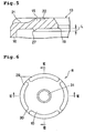
- Fig. 5 shows a vertical section of the receiving projection 27.
- the vertical section passes through the central axis 28 of the opening 6.
- the sectional shape of the lower edge of the receiving projection 27 is formed to have an angle of 90 degrees or less, for example, 45 degrees.
- the surface facing radially outward of the receiving projection 27 stands vertically along the central axis 28.
- the height L of the receiving projection 27 is set at, for example, 0.5 mm.
- the seal member 8 has a compressible projection 29 on the upper surface of the flange 10. As shown in Figs. 6 to 8 , in a planar view, the compressible projection 29 is annularly arranged in contact with and along the outer circumference of the flange 10. Consequently, the height of the lateral surface of the flange 10 is increased in the vertical direction by the height of the compressible projection 29, as shown in, for example, Figs. 7 and 8 .
- the cap 9 and the seal member 8 are to be attached to the vial 2 in the incompletely sealing state Y as shown in Fig.
- the compressible projection 29 has four discontinuous parts 30 in the circumference direction, and the space surrounded by the compressible projection 29 communicates with the outside via these discontinuous parts 30.
- This structure can effectively prevent the seal member 8 from adhering by suction to attaching means, a handling device, various kinds of processing apparatuses, or the like, as if the seal member were a sucking disk, upon the attachment of the seal member 8 to the vial 2 in the incompletely sealing state Y, or during processing before the attachment, such as handling, washing, and sterilization.
- a depression for needle insertion 31 is provided on the center of the upper surface of the flange 10.
- the four discontinuous parts 30 provided on the compressible projection 29 in the circumference direction three or less, or five or more discontinuous parts may be provided in the circumference direction.
- the receiving projection 27 is positioned radially inward relative to the compressible projection 29.
- the receiving projection 27 is intended to receive the compressible projection 29 in order to prevent the seal member 8 from moving radially inward or being deformed.
- the height h of the compressible projection 29 is set at, for example, 0.8 mm. When the thickness t of the flange 10 excluding the compressible projection 29 is, for example, 3.5 mm, this height is set at about 23%.
- the closure device 1 is to be attached to the vial 2 in the incompletely sealing state Y as shown in Fig. 1 .
- the vial 2 is placed in a lyophilization apparatus (not shown), and the content of the vial 2 is lyophilized under reduced pressure.
- the vial 2 is pressed down from the above by a shelf of the lyophilization apparatus so that the closure device 1 on the vial 2 is pushed down to the sealing state X as shown in Fig. 2 .
- the top wall 15 of the cap body 13 presses down the compressible projection 29 of the seal member 8, and then presses down part of the flange 10 just under the compressible projection 29.
- the top wall 15 presses down the other part of the flange 10.
- the receiving projection 27 bites into the upper surface of the flange 10 as shown in Fig. 2 , and the flange 10 is consequently firmly held between the top wall 15 of the cap 9 and the upper surface of the vial 2 and prevented from moving radially inward.
- the compressible projection 29 is merely part of the entire flange 10, and consequently the compressible projection 29 is easily pressed down with a small pressing force. Via the compressible projection 29, the flange 10 under the compressible projection 29 is pressed against the upper surface around the opening 6 of the vial 2. Since the compressible projection 29 is annularly arranged along the outer circumference of the flange 10, the downward pressing force through the compressible projection 29 presses part of the flange 10 just under the compressible projection against the upper surface of the vial 2 and, as a result, the opening 6 of the vial 2 is sealed from the outside.
- the height of the compressible projection 29 is set so as to sufficiently absorb each size variation occurring within the tolerance. Owing to the height, even a small pressing force, for example about 30 N per vial, is sufficient to ensure capping of the opening 6 of the vial 2.
- the compressible projection 29 is in contact with the outer circumference of the flange 10 in a planar view and thus the flange 10's upper surface surrounded by the outer circumference of the compressible projection 29 is most extensive; thus pressing force through the cap 9 is evenly distributed and the flange 10 is pressed down uniformly. Moreover, when pressed down by the top wall 15 of the cap 9, the upper surface of the seal member 8 is stably kept in horizontal and the seal member 8 is set onto the opening 6 in a proper state.
- the content of the vial 2 that is sealed with the closure device 1 is taken out as needed according to the following process.
- the lid 14 of the cap 9 is removed from the cap body 13 by breaking the joining projections 23, and the depression for needle insertion 31 on the seal member 8 is exposed to the outside through the window for needle entry 19.
- an injection needle is inserted into the vial through the depression for needle insertion 31 in order to inject a dissolving solution or the like for reconstituting the content of the storage part 4 of the vial 2. The content is then pumped out with the injection needle.
- the structure having the receiving projection 27 that bites into the upper surface of the flange 10 and the receiving projection 27 that receives the compressible projection 29 prevents the flange 10 from moving radially inward.
- This structure also prevents the seal member 8 from being deformed toward the inside of the vial 2. Further, even when the tip of the injection needle accidentally sticks into the leg, the structure prevents the flange 10 from being drawn into the vial 2 along with the leg. Thus the structure ensures smooth insertion of the injection needle into the vial 2 through the seal member 8.
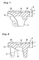
- the receiving projection 27 has a sectional shape whose surface facing radially outward stands vertically along the central axis 28 of the opening 6.
- the sectional shape of the receiving projection of the present invention is not limited to a particular shape.
- the angle of the lower edge of the receiving projection 27 is set at about 60 degrees.
- the sharp angle ( ⁇ ) between the surface facing radially outward and the vertical line is set at 45 degrees or less, for example, 30 degrees.
- Fig. 10 shows Modified Example 2 of an embodiment of the present invention.
- a stabilizer 32 is provided in each of the ventilation openings 26 that are longitudinally provided between each locking part 18.
- the diameter of a virtual circle that passes through the inner edges of each stabilizer 32 is set at about the same as the outer diameter of the rim 7 of the vial 2, or slightly smaller than the outer diameter of the rim 7; thus the cap having said locking member 17 is to be attached to the vial in a proper incompletely sealing state Y, in which the central axis of the cylinder part 16 corresponds with the central axis 28 of the opening 6 of the vial 2.
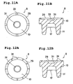
- the compressible projection 29 on the seal member 8 can be formed into various shapes as needed, for example, as shown in Modified Examples in Figs. 11A to 17B .
- the compressible projection 29 is formed into a continuous annular ring not having any gaps.
- This compressible projection 29 has a plurality of lower parts 33, whose heights are lower than that of the annular ring.
- the lower parts 33 allow the space surrounded by the compressible projection 29 to communicate with the outside, and thus prevent the seal member 8 from adhering by suction to other things.
- the compressible projection 29 is formed into the same continuous annular ring not having any gaps as in Modified Example 3 except that, instead of the lower parts 33, projections for adhesion prevention 34 are formed on the upper surface of the compressible projection 29 in order to prevent the seal member 8 from adhering to other things.
- the space around the projections for adhesion prevention 34 allows the space surrounded by the compressible projection 29 to communicate with the outside.
- the compressible projection 29 is formed into dots that are annularly disposed in a planar view.
- the compressible projections 29 are connected to each other by an annular portion 35, which is positioned under the compressible projections 29.
- a plurality of the compressible projections 29 are formed along the outer circumference of the flange 10.
- the compressible projections 29 are each formed into an oval body that extends radially inward in a planar view. When the compressible projections 29 are pressed down by the top wall of the cap, the flange 10 under the compressible projections 29 is extensively pressed against the upper surface of the vial 2.
- the seal member 8 has the depression for needle insertion 31 in the center of the upper surface of the flange 10.
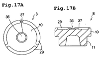
- the depression for needle insertion 31 may be omitted, and a needle insertion site 36 having the same thickness as the thickness t of the flange 10 may be provided in the center of the upper surface of the flange 10. Examples of the needle insertion site 36 are shown in Modified Example 7 in Figs. 15A and 15B and Modified Example 8 in Figs. 16A and 16B .
- the seal member 8 has four compressible projections 29 that is arranged along the outer circumference of the upper surface of the flange 10.
- the center of the upper surface of the flange 10 has no depression for needle insertion but has the needle insertion site 36 that has the same thickness as the thickness t of the flange 10 and is surrounded by an annular ridge 37.
- the annular ridge 37 is formed into an annular ring not having any gaps.
- the projection height of the annular ridge 37 is lower than that of the compressible projection 29, and therefore there is no risk that the annular ridge 37 would be in contact with or adhere by suction to other things during processing such as handling, washing, and sterilization.
- the closure device of the present invention can also be attached to a container for containing a powder preparation, a liquid preparation, or the like. In this case, attachment in the incompletely sealing state is not required: after desired contents are put in the container, the closure device only has to be attached to the opening in the sealing state.
- the leg 11 of the seal member 8 is formed into a shorter cylinder as shown in, for example.
- Modified Example 9 in Figs. 17A and 17B .
- the notch 12 provided in the above embodiments and Modified Examples is omitted from the leg 11 in Modified Example 9.
- the other structures and their functions are the same as those of Modified Example 8, and the explanations for them are omitted accordingly.
- the above embodiments are preferable in that the combination of the compressible projection on the seal member and the receiving projection on the top wall of the cap enables the seal member to seal the opening and to suitably keep the sealing state.
- the compressible projection is not limited to the above embodiments or Modified Examples.
- the compressible projection may be any other projection that also has another use, for example, a projection that prevents adhesion to other things during handling.
- the compressible projection may be positioned radially inward relative to the outer circumference of the flange as long as the compressible projection is positioned radially outward relative to the receiving projection. In the present invention, either of the compressible projection and the receiving projection may be omitted.
- the locking part is formed on the locking member, which is a different member from the cylinder part.
- the locking part may be integrated into the cylinder part.
- the cylinder part may have a slit or a vent that connects the storage part of the vial to the outside.
- the window for needle entry that is provided in the top wall of the cap body is covered with the lid, and the lid is removed by breaking the joining projection.
- This structure enables an opened vial to be easily distinguished from an unopened vial.
- the lid may be omitted and the window for needle entry may be covered with, for example, a closure film that is unable to be re-sealed, or the like.
- a synthetic rubber material such as a butyl rubber is used for the seal member.
- the seal member may be made of a material whose main raw material is another synthetic rubber, a thermoplastic elastomer, or the like.
- explanations are made for cases where the content is lyophilized.
- other kinds of contents such as a powder preparation and a liquid preparation may be contained in the vial for the present invention without being lyophilized.
- the inside of the vial may be at positive pressure, besides in vacuo or at reduced pressure, and also may be filled up with an inert gas such as nitrogen gas.
- the sectional shape, size, or the like of the receiving projection and the compressible projection is not limited to the above embodiments.
Claims (12)
- Dispositif de fermeture pour un récipient, qui ferme de manière étanche une ouverture (6) qui s'ouvre au sommet d'un récipient (2) et comporte un rebord (7) sur sa périphérie, comprenant :un élément d'étanchement (8) destiné à couvrir l'ouverture (6) et présentant l'élasticité du caoutchouc, comprenantune bride (10) destinée à être montée sur la surface supérieure du rebord (7), etune projection compressible (29) qui se projette vers le haut depuis la surface supérieure de la bride (10) et qui est agencée de manière annulaire en contact avec et le long de la circonférence extérieure de la bride (10) dans une vue en plan ; etun capuchon en résine synthétique (9) destiné à presser et ainsi tenir l'élément d'étanchement (8) sur la surface supérieure du rebord (7), comprenantune paroi supérieure (15) destinée à être disposée au-dessus de la bride (10),une partie en cylindre (16) qui est suspendue vers le bas depuis la circonférence extérieure de la paroi supérieure (15),une partie de blocage (18) qui est disposée sur la surface intérieure de la partie en cylindre (16) et, après avoir poussé le capuchon (9) vers le bas, se bloque à la surface de dessous du rebord (7), etune projection de réception (27) qui se projette vers le bas depuis une partie annulaire sur la surface inférieure de la paroi supérieure (15), la partie annulaire ayant un diamètre intérieur qui est plus grand que celui de l'ouverture (7), et un diamètre extérieur qui est plus petit que celui de la bride (10) de l'élément d'étanchement (8),dans lequel au moins une partie de la projection compressible (29) est positionnée radialement à l'extérieur par rapport à la projection de réception (27).
- Dispositif de fermeture pour un récipient selon la revendication 1, dans lequel la projection compressible (29) est formée en une bague annulaire discontinue qui est agencée le long de la circonférence extérieure de la bride (10).
- Dispositif de fermeture pour un récipient selon la revendication 2, dans lequel une pluralité de projections compressibles (29) sont agencées le long de la circonférence extérieure de la bride (10) et s'étendent radialement vers l'intérieur depuis la circonférence extérieure de la bride (10).
- Dispositif de fermeture pour un récipient selon l'une quelconque des revendications 1 à 3, dans lequel la projection de réception (27) est une bague annulaire qui entoure l'ouverture (6) dans une vue en plan.
- Dispositif de fermeture pour un récipient selon l'une quelconque des revendications 1 à 4, dans lequel la hauteur (h) de la projection compressible (29) est de 10 à 60 % de l'épaisseur (t) de la bride (10), en excluant la projection compressible (29).
- Dispositif de fermeture pour un récipient selon l'une quelconque des revendications 1 à 5, dans lequel l'élément d'étanchement (8) est réalisé avec au moins un parmi un matériau en caoutchouc synthétique et un élastomère thermoplastique.
- Dispositif de fermeture pour un récipient selon l'une quelconque des revendications 1 à 6, dans lequel le contenu du récipient (2) est une préparation quelconque parmi une préparation lyophilisée, une préparation en poudre, et une préparation liquide.
- Dispositif de fermeture pour un récipient selon l'une quelconque des revendications 1 à 7, dans lequel, dans une section verticale qui passe par l'axe central de l'ouverture (6), le bord inférieur de la projection de réception (27) présente un angle de 90° ou moins.
- Dispositif de fermeture pour un récipient selon l'une quelconque des revendications 1 à 8, dans lequel, dans une section verticale qui passe par l'axe central de l'ouverture (6), la projection de réception (27) présente un angle aigu (α) de 45° ou moins entre la surface tournée radialement vers l'extérieur et la ligne verticale.
- Dispositif de fermeture pour un récipient selon l'une quelconque des revendications 1 à 9, dans lequel la hauteur (L) de la projection de réception (27) est de 0,3 à 2,0 mm.
- Élément d'étanchement (8) pour le dispositif de fermeture (1) pour un récipient (2) selon l'une quelconque des revendications 1 à 10, comprenant :une bride en forme de disque (10),une patte (11) qui est suspendue vers le bas depuis la surface inférieure de la bride (10), etune projection compressible (29) qui se projette vers le haut depuis la surface inférieure de la bride (10) et qui est agencée de manière annulaire en contact-avec la circonférence extérieure de la bride (10) dans une vue en plan.
- Élément d'étanchement selon la revendication 11, dans lequel l'élément d'étanchement (8) est réalisé d'au moins un matériau parmi un matériau au caoutchouc synthétique et un élastomère thermoplastique.
Applications Claiming Priority (2)
| Application Number | Priority Date | Filing Date | Title |
|---|---|---|---|
| JP2010105555A JP5683129B2 (ja) | 2010-04-30 | 2010-04-30 | バイアル用栓体とこれに用いるシール部材 |
| JP2010105547A JP5566765B2 (ja) | 2010-04-30 | 2010-04-30 | バイアル用栓体 |
Publications (2)
| Publication Number | Publication Date |
|---|---|
| EP2383199A1 EP2383199A1 (fr) | 2011-11-02 |
| EP2383199B1 true EP2383199B1 (fr) | 2013-06-12 |
Family
ID=44123193
Family Applications (1)
| Application Number | Title | Priority Date | Filing Date |
|---|---|---|---|
| EP20110003090 Active EP2383199B1 (fr) | 2010-04-30 | 2011-04-12 | Dispositif de fermeture pour récipient et élément d'étanchéité pour le dispositif |
Country Status (3)
| Country | Link |
|---|---|
| US (1) | US8978909B2 (fr) |
| EP (1) | EP2383199B1 (fr) |
| CN (1) | CN102259723B (fr) |
Cited By (1)
| Publication number | Priority date | Publication date | Assignee | Title |
|---|---|---|---|---|
| US10195112B2 (en) | 2012-11-26 | 2019-02-05 | Becton Dickinson France | Adaptor for multidose medical container |
Families Citing this family (24)
| Publication number | Priority date | Publication date | Assignee | Title |
|---|---|---|---|---|
| FR2967655B1 (fr) * | 2010-11-24 | 2014-03-14 | Biocorp Rech Et Dev | Dispositif de bouchage d'un recipient, recipient equipe d'un tel dispositif et procede de fermeture d'un lot de tels recipients |
| SG192312A1 (en) | 2012-02-02 | 2013-08-30 | Becton Dickinson Holdings Pte Ltd | Adaptor for coupling to a medical container |
| MX358074B (es) | 2012-02-02 | 2018-08-03 | Becton Dickinson Holdings Pte Ltd | Acoplamiento de un contenedor medico mediante un adaptador. |
| SG192310A1 (en) | 2012-02-02 | 2013-08-30 | Becton Dickinson Holdings Pte Ltd | Adaptor for coupling to a medical container |
| EP2692328A1 (fr) | 2012-08-03 | 2014-02-05 | Becton Dickinson France | Dispositif de comptage de doses pour couplage avec un récipient médical |
| KR101976097B1 (ko) * | 2012-11-12 | 2019-05-09 | 쇼오트 아게 | 의료, 의약 또는 화장품 용도의 물질용 용기를 조작 또는 처리하는 프로세스 및 장치 |
| US10327986B2 (en) * | 2013-07-03 | 2019-06-25 | Sio2 Medical Products, Inc. | Parenteral vial cap |
| JP1526207S (fr) | 2013-08-05 | 2015-06-15 | ||
| US9555940B2 (en) * | 2013-09-02 | 2017-01-31 | Taisei Kako Co., Ltd. | Cap for vial |
| JP6403258B2 (ja) * | 2014-09-16 | 2018-10-10 | 住友ゴム工業株式会社 | 医療用ゴム栓の製造方法 |
| US10099823B2 (en) * | 2014-11-18 | 2018-10-16 | Daikyo Seiko, Ltd. | Vial cap |
| CN106963641B (zh) * | 2016-01-14 | 2024-03-01 | 雷诺丽特恒迅包装科技(北京)有限公司 | 一种组合盖和具有该组合盖的输液容器 |
| MX2019003581A (es) * | 2016-09-28 | 2019-05-27 | Fresenius Kabi Deutschland Gmbh | Tapa de cierre para recipiente para alojamiento de liquido medico. |
| CN109759987B (zh) * | 2017-11-09 | 2020-11-06 | 河南平芝高压开关有限公司 | 一种屏蔽罩压装工装 |
| EP3502010A1 (fr) * | 2017-12-19 | 2019-06-26 | Clariant Healthcare Packaging (France) SAS | Dispositif limiteur de débit et bouchon pour un récipient le comprenant |
| CN112004756B (zh) * | 2018-01-19 | 2021-11-19 | 西部制药服务有限公司(德国) | 封堵装置 |
| CN113474083A (zh) * | 2019-01-04 | 2021-10-01 | 仪器实验室公司 | 用于高刺穿计数应用的容器塞子 |
| EP3995123A4 (fr) * | 2019-07-02 | 2023-08-09 | Taisei Kako Co., Ltd. | Capuchon et flacon avec capuchon |
| FR3098504B1 (fr) * | 2019-07-09 | 2021-06-04 | A Raymond Et Cie | coiffe de verrouillage pour récipient à col |
| WO2021032653A1 (fr) * | 2019-08-21 | 2021-02-25 | Sanofi | Fermeture pour contenant de médicament |
| FR3105023B1 (fr) * | 2019-12-20 | 2022-06-03 | Abc Transfer | Conteneur etanche pourvu d’une bride bi-matiere |
| FR3106339B1 (fr) * | 2020-01-16 | 2021-12-24 | A Raymond Et Cie | Coiffe de verrouillage pour recipient a col avec une capsule a pattes de fixation secables |
| CN114955209A (zh) * | 2021-02-25 | 2022-08-30 | 叙事有限公司 | 具有可拆卸的开口封闭件及密封装置的袋式容器 |
| EP4253276A1 (fr) * | 2022-03-30 | 2023-10-04 | Datwyler Pharma Packaging Belgium | Bouchons pour récipients contenant des substances médicales ou pharmaceutiques |
Family Cites Families (12)
| Publication number | Priority date | Publication date | Assignee | Title |
|---|---|---|---|---|
| NO150234C (no) * | 1977-05-09 | 1984-09-12 | Asicomo As | Kapselformet lukke for beholderaapning og fremgangsmaate til fremstilling av lukket |
| JPS56119254A (en) | 1980-02-25 | 1981-09-18 | Takeda Chemical Industries Ltd | Rubber stopper for vial |
| JPH052182Y2 (fr) | 1985-07-15 | 1993-01-20 | ||
| DE4228090C2 (de) * | 1992-08-24 | 1995-01-05 | Pohl Gmbh & Co Kg | Verschluß für eine Flasche |
| US5328041A (en) * | 1993-06-30 | 1994-07-12 | Abbott Laboratories | Two piece stopper for blunt fluid connector |
| JP2757117B2 (ja) | 1993-10-21 | 1998-05-25 | 三共株式会社 | バイアル容器 |
| FR2745794B1 (fr) * | 1996-03-05 | 1998-05-22 | Rumpler Technologies | Dispositif de bouchage pour un recipient tel qu'en particulier un flacon a usage medical |
| US5718348A (en) * | 1996-09-12 | 1998-02-17 | Comar, Inc. | Overcap assembly for gear finish vial |
| JPH1147234A (ja) * | 1997-07-29 | 1999-02-23 | Naniwa Rubber Kogyo Kk | 医療用ゴム栓 |
| DE19754625C2 (de) * | 1997-12-09 | 2002-01-24 | Helvoet Pharma | Stopfen zum Verschließen von Infusionsflaschen |
| JP2001245956A (ja) | 2000-03-03 | 2001-09-11 | Ohtsu Tire & Rubber Co Ltd :The | 医療用ゴム栓 |
| JP2003128095A (ja) | 2001-10-24 | 2003-05-08 | Ohtsu Tire & Rubber Co Ltd :The | 医薬用ゴム栓およびその製造方法 |
-
2011
- 2011-04-12 EP EP20110003090 patent/EP2383199B1/fr active Active
- 2011-04-27 CN CN201110111651.4A patent/CN102259723B/zh active Active
- 2011-04-29 US US13/097,178 patent/US8978909B2/en active Active
Cited By (1)
| Publication number | Priority date | Publication date | Assignee | Title |
|---|---|---|---|---|
| US10195112B2 (en) | 2012-11-26 | 2019-02-05 | Becton Dickinson France | Adaptor for multidose medical container |
Also Published As
| Publication number | Publication date |
|---|---|
| CN102259723A (zh) | 2011-11-30 |
| CN102259723B (zh) | 2015-08-26 |
| US20110266249A1 (en) | 2011-11-03 |
| EP2383199A1 (fr) | 2011-11-02 |
| US8978909B2 (en) | 2015-03-17 |
Similar Documents
| Publication | Publication Date | Title |
|---|---|---|
| EP2383199B1 (fr) | Dispositif de fermeture pour récipient et élément d'étanchéité pour le dispositif | |
| CA2949219C (fr) | Procede de fermeture hermetique d'une bouteille et bouteille a fermeture hermetique correspondante | |
| US10472132B2 (en) | Closing assembly for a bottle, associated bottle and assembly method | |
| EP2694390B1 (fr) | Systèmes de capuchon et procédés pour sceller de façon étanche des flacons pharmaceutiques | |
| EP1093784B1 (fr) | Ensemble de transfert pour fioles et récipients médicaux | |
| US4193402A (en) | Bottle stopper and method of using said stopper | |
| CA2677286C (fr) | Capuchon de fermeture pour un recipient destine a recevoir des liquides medicaux et recipient destine a recevoir des liquides medicaux | |
| CN106659634B (zh) | 用于药品的容器的封闭装置以及用于封闭小瓶的方法 | |
| KR20210006847A (ko) | 네크를 포함하는 용기를 위한 파단 가능한 로킹 캡 | |
| CN112004756B (zh) | 封堵装置 | |
| JP5683129B2 (ja) | バイアル用栓体とこれに用いるシール部材 | |
| RU2517242C2 (ru) | Укупорочный колпачок для контейнеров | |
| JP5566765B2 (ja) | バイアル用栓体 | |
| CA1052732A (fr) | Contenant sterile refermable | |
| US20030201239A1 (en) | Radially compressed self-sealing septum | |
| JP4698056B2 (ja) | 医療用ゴム栓 | |
| WO2022137609A1 (fr) | Bouchon en caoutchouc | |
| CN114206746A (zh) | 小瓶封闭组件 | |
| WO1999061335A1 (fr) | Ensemble col de bouteille muni d'un bouchon |
Legal Events
| Date | Code | Title | Description |
|---|---|---|---|
| AK | Designated contracting states |
Kind code of ref document: A1 Designated state(s): AL AT BE BG CH CY CZ DE DK EE ES FI FR GB GR HR HU IE IS IT LI LT LU LV MC MK MT NL NO PL PT RO RS SE SI SK SM TR |
|
| AX | Request for extension of the european patent |
Extension state: BA ME |
|
| PUAI | Public reference made under article 153(3) epc to a published international application that has entered the european phase |
Free format text: ORIGINAL CODE: 0009012 |
|
| 17P | Request for examination filed |
Effective date: 20120502 |
|
| GRAP | Despatch of communication of intention to grant a patent |
Free format text: ORIGINAL CODE: EPIDOSNIGR1 |
|
| GRAP | Despatch of communication of intention to grant a patent |
Free format text: ORIGINAL CODE: EPIDOSNIGR1 |
|
| RIN1 | Information on inventor provided before grant (corrected) |
Inventor name: MIYAMOTO, NORIKAZU Inventor name: KAKUTANI, MASAHIRO Inventor name: SHIRAI, TOMOHITO Inventor name: YAO, EIJI Inventor name: MAEDA, KATSUSHI |
|
| GRAS | Grant fee paid |
Free format text: ORIGINAL CODE: EPIDOSNIGR3 |
|
| GRAA | (expected) grant |
Free format text: ORIGINAL CODE: 0009210 |
|
| AK | Designated contracting states |
Kind code of ref document: B1 Designated state(s): AL AT BE BG CH CY CZ DE DK EE ES FI FR GB GR HR HU IE IS IT LI LT LU LV MC MK MT NL NO PL PT RO RS SE SI SK SM TR |
|
| REG | Reference to a national code |
Ref country code: GB Ref legal event code: FG4D |
|
| REG | Reference to a national code |
Ref country code: CH Ref legal event code: EP |
|
| REG | Reference to a national code |
Ref country code: AT Ref legal event code: REF Ref document number: 616595 Country of ref document: AT Kind code of ref document: T Effective date: 20130615 |
|
| REG | Reference to a national code |
Ref country code: IE Ref legal event code: FG4D |
|
| REG | Reference to a national code |
Ref country code: DE Ref legal event code: R096 Ref document number: 602011001967 Country of ref document: DE Effective date: 20130808 |
|
| PG25 | Lapsed in a contracting state [announced via postgrant information from national office to epo] |
Ref country code: NO Free format text: LAPSE BECAUSE OF FAILURE TO SUBMIT A TRANSLATION OF THE DESCRIPTION OR TO PAY THE FEE WITHIN THE PRESCRIBED TIME-LIMIT Effective date: 20130912 Ref country code: ES Free format text: LAPSE BECAUSE OF FAILURE TO SUBMIT A TRANSLATION OF THE DESCRIPTION OR TO PAY THE FEE WITHIN THE PRESCRIBED TIME-LIMIT Effective date: 20130923 Ref country code: FI Free format text: LAPSE BECAUSE OF FAILURE TO SUBMIT A TRANSLATION OF THE DESCRIPTION OR TO PAY THE FEE WITHIN THE PRESCRIBED TIME-LIMIT Effective date: 20130612 Ref country code: SE Free format text: LAPSE BECAUSE OF FAILURE TO SUBMIT A TRANSLATION OF THE DESCRIPTION OR TO PAY THE FEE WITHIN THE PRESCRIBED TIME-LIMIT Effective date: 20130612 Ref country code: GR Free format text: LAPSE BECAUSE OF FAILURE TO SUBMIT A TRANSLATION OF THE DESCRIPTION OR TO PAY THE FEE WITHIN THE PRESCRIBED TIME-LIMIT Effective date: 20130913 Ref country code: LT Free format text: LAPSE BECAUSE OF FAILURE TO SUBMIT A TRANSLATION OF THE DESCRIPTION OR TO PAY THE FEE WITHIN THE PRESCRIBED TIME-LIMIT Effective date: 20130612 Ref country code: SI Free format text: LAPSE BECAUSE OF FAILURE TO SUBMIT A TRANSLATION OF THE DESCRIPTION OR TO PAY THE FEE WITHIN THE PRESCRIBED TIME-LIMIT Effective date: 20130612 |
|
| REG | Reference to a national code |
Ref country code: AT Ref legal event code: MK05 Ref document number: 616595 Country of ref document: AT Kind code of ref document: T Effective date: 20130612 |
|
| REG | Reference to a national code |
Ref country code: NL Ref legal event code: VDEP Effective date: 20130612 |
|
| REG | Reference to a national code |
Ref country code: LT Ref legal event code: MG4D |
|
| PG25 | Lapsed in a contracting state [announced via postgrant information from national office to epo] |
Ref country code: HR Free format text: LAPSE BECAUSE OF FAILURE TO SUBMIT A TRANSLATION OF THE DESCRIPTION OR TO PAY THE FEE WITHIN THE PRESCRIBED TIME-LIMIT Effective date: 20130612 Ref country code: RS Free format text: LAPSE BECAUSE OF FAILURE TO SUBMIT A TRANSLATION OF THE DESCRIPTION OR TO PAY THE FEE WITHIN THE PRESCRIBED TIME-LIMIT Effective date: 20130612 Ref country code: BG Free format text: LAPSE BECAUSE OF FAILURE TO SUBMIT A TRANSLATION OF THE DESCRIPTION OR TO PAY THE FEE WITHIN THE PRESCRIBED TIME-LIMIT Effective date: 20130912 |
|
| PG25 | Lapsed in a contracting state [announced via postgrant information from national office to epo] |
Ref country code: LV Free format text: LAPSE BECAUSE OF FAILURE TO SUBMIT A TRANSLATION OF THE DESCRIPTION OR TO PAY THE FEE WITHIN THE PRESCRIBED TIME-LIMIT Effective date: 20130612 |
|
| PG25 | Lapsed in a contracting state [announced via postgrant information from national office to epo] |
Ref country code: EE Free format text: LAPSE BECAUSE OF FAILURE TO SUBMIT A TRANSLATION OF THE DESCRIPTION OR TO PAY THE FEE WITHIN THE PRESCRIBED TIME-LIMIT Effective date: 20130612 Ref country code: IS Free format text: LAPSE BECAUSE OF FAILURE TO SUBMIT A TRANSLATION OF THE DESCRIPTION OR TO PAY THE FEE WITHIN THE PRESCRIBED TIME-LIMIT Effective date: 20131012 Ref country code: BE Free format text: LAPSE BECAUSE OF FAILURE TO SUBMIT A TRANSLATION OF THE DESCRIPTION OR TO PAY THE FEE WITHIN THE PRESCRIBED TIME-LIMIT Effective date: 20130612 Ref country code: CZ Free format text: LAPSE BECAUSE OF FAILURE TO SUBMIT A TRANSLATION OF THE DESCRIPTION OR TO PAY THE FEE WITHIN THE PRESCRIBED TIME-LIMIT Effective date: 20130612 Ref country code: AT Free format text: LAPSE BECAUSE OF FAILURE TO SUBMIT A TRANSLATION OF THE DESCRIPTION OR TO PAY THE FEE WITHIN THE PRESCRIBED TIME-LIMIT Effective date: 20130612 Ref country code: PT Free format text: LAPSE BECAUSE OF FAILURE TO SUBMIT A TRANSLATION OF THE DESCRIPTION OR TO PAY THE FEE WITHIN THE PRESCRIBED TIME-LIMIT Effective date: 20131014 Ref country code: SK Free format text: LAPSE BECAUSE OF FAILURE TO SUBMIT A TRANSLATION OF THE DESCRIPTION OR TO PAY THE FEE WITHIN THE PRESCRIBED TIME-LIMIT Effective date: 20130612 |
|
| PG25 | Lapsed in a contracting state [announced via postgrant information from national office to epo] |
Ref country code: NL Free format text: LAPSE BECAUSE OF FAILURE TO SUBMIT A TRANSLATION OF THE DESCRIPTION OR TO PAY THE FEE WITHIN THE PRESCRIBED TIME-LIMIT Effective date: 20130612 Ref country code: PL Free format text: LAPSE BECAUSE OF FAILURE TO SUBMIT A TRANSLATION OF THE DESCRIPTION OR TO PAY THE FEE WITHIN THE PRESCRIBED TIME-LIMIT Effective date: 20130612 Ref country code: RO Free format text: LAPSE BECAUSE OF FAILURE TO SUBMIT A TRANSLATION OF THE DESCRIPTION OR TO PAY THE FEE WITHIN THE PRESCRIBED TIME-LIMIT Effective date: 20130612 |
|
| PLBE | No opposition filed within time limit |
Free format text: ORIGINAL CODE: 0009261 |
|
| STAA | Information on the status of an ep patent application or granted ep patent |
Free format text: STATUS: NO OPPOSITION FILED WITHIN TIME LIMIT |
|
| PG25 | Lapsed in a contracting state [announced via postgrant information from national office to epo] |
Ref country code: DK Free format text: LAPSE BECAUSE OF FAILURE TO SUBMIT A TRANSLATION OF THE DESCRIPTION OR TO PAY THE FEE WITHIN THE PRESCRIBED TIME-LIMIT Effective date: 20130612 |
|
| 26N | No opposition filed |
Effective date: 20140313 |
|
| PG25 | Lapsed in a contracting state [announced via postgrant information from national office to epo] |
Ref country code: IT Free format text: LAPSE BECAUSE OF FAILURE TO SUBMIT A TRANSLATION OF THE DESCRIPTION OR TO PAY THE FEE WITHIN THE PRESCRIBED TIME-LIMIT Effective date: 20130612 |
|
| REG | Reference to a national code |
Ref country code: DE Ref legal event code: R097 Ref document number: 602011001967 Country of ref document: DE Effective date: 20140313 |
|
| PG25 | Lapsed in a contracting state [announced via postgrant information from national office to epo] |
Ref country code: LU Free format text: LAPSE BECAUSE OF FAILURE TO SUBMIT A TRANSLATION OF THE DESCRIPTION OR TO PAY THE FEE WITHIN THE PRESCRIBED TIME-LIMIT Effective date: 20140412 Ref country code: MC Free format text: LAPSE BECAUSE OF FAILURE TO SUBMIT A TRANSLATION OF THE DESCRIPTION OR TO PAY THE FEE WITHIN THE PRESCRIBED TIME-LIMIT Effective date: 20130612 |
|
| REG | Reference to a national code |
Ref country code: CH Ref legal event code: PL |
|
| REG | Reference to a national code |
Ref country code: IE Ref legal event code: MM4A |
|
| PG25 | Lapsed in a contracting state [announced via postgrant information from national office to epo] |
Ref country code: LI Free format text: LAPSE BECAUSE OF NON-PAYMENT OF DUE FEES Effective date: 20140430 Ref country code: CH Free format text: LAPSE BECAUSE OF NON-PAYMENT OF DUE FEES Effective date: 20140430 |
|
| PG25 | Lapsed in a contracting state [announced via postgrant information from national office to epo] |
Ref country code: IE Free format text: LAPSE BECAUSE OF NON-PAYMENT OF DUE FEES Effective date: 20140412 |
|
| REG | Reference to a national code |
Ref country code: FR Ref legal event code: PLFP Year of fee payment: 6 |
|
| PG25 | Lapsed in a contracting state [announced via postgrant information from national office to epo] |
Ref country code: MT Free format text: LAPSE BECAUSE OF FAILURE TO SUBMIT A TRANSLATION OF THE DESCRIPTION OR TO PAY THE FEE WITHIN THE PRESCRIBED TIME-LIMIT Effective date: 20130612 |
|
| PG25 | Lapsed in a contracting state [announced via postgrant information from national office to epo] |
Ref country code: SM Free format text: LAPSE BECAUSE OF FAILURE TO SUBMIT A TRANSLATION OF THE DESCRIPTION OR TO PAY THE FEE WITHIN THE PRESCRIBED TIME-LIMIT Effective date: 20130612 |
|
| PG25 | Lapsed in a contracting state [announced via postgrant information from national office to epo] |
Ref country code: CY Free format text: LAPSE BECAUSE OF FAILURE TO SUBMIT A TRANSLATION OF THE DESCRIPTION OR TO PAY THE FEE WITHIN THE PRESCRIBED TIME-LIMIT Effective date: 20130612 |
|
| PG25 | Lapsed in a contracting state [announced via postgrant information from national office to epo] |
Ref country code: HU Free format text: LAPSE BECAUSE OF FAILURE TO SUBMIT A TRANSLATION OF THE DESCRIPTION OR TO PAY THE FEE WITHIN THE PRESCRIBED TIME-LIMIT; INVALID AB INITIO Effective date: 20110412 Ref country code: TR Free format text: LAPSE BECAUSE OF FAILURE TO SUBMIT A TRANSLATION OF THE DESCRIPTION OR TO PAY THE FEE WITHIN THE PRESCRIBED TIME-LIMIT Effective date: 20130612 |
|
| REG | Reference to a national code |
Ref country code: FR Ref legal event code: PLFP Year of fee payment: 7 |
|
| REG | Reference to a national code |
Ref country code: FR Ref legal event code: PLFP Year of fee payment: 8 |
|
| PG25 | Lapsed in a contracting state [announced via postgrant information from national office to epo] |
Ref country code: MK Free format text: LAPSE BECAUSE OF FAILURE TO SUBMIT A TRANSLATION OF THE DESCRIPTION OR TO PAY THE FEE WITHIN THE PRESCRIBED TIME-LIMIT Effective date: 20130612 |
|
| PG25 | Lapsed in a contracting state [announced via postgrant information from national office to epo] |
Ref country code: AL Free format text: LAPSE BECAUSE OF FAILURE TO SUBMIT A TRANSLATION OF THE DESCRIPTION OR TO PAY THE FEE WITHIN THE PRESCRIBED TIME-LIMIT Effective date: 20130612 |
|
| PGFP | Annual fee paid to national office [announced via postgrant information from national office to epo] |
Ref country code: FR Payment date: 20230309 Year of fee payment: 13 |
|
| PGFP | Annual fee paid to national office [announced via postgrant information from national office to epo] |
Ref country code: GB Payment date: 20230302 Year of fee payment: 13 |
|
| P01 | Opt-out of the competence of the unified patent court (upc) registered |
Effective date: 20230510 |
|
| PGFP | Annual fee paid to national office [announced via postgrant information from national office to epo] |
Ref country code: DE Payment date: 20230228 Year of fee payment: 13 |