EP2381602B1 - Method of positioning of signal - Google Patents
Method of positioning of signal Download PDFInfo
- Publication number
- EP2381602B1 EP2381602B1 EP09834788.3A EP09834788A EP2381602B1 EP 2381602 B1 EP2381602 B1 EP 2381602B1 EP 09834788 A EP09834788 A EP 09834788A EP 2381602 B1 EP2381602 B1 EP 2381602B1
- Authority
- EP
- European Patent Office
- Prior art keywords
- data symbols
- signal
- bits
- symbols
- symbol
- Prior art date
- Legal status (The legal status is an assumption and is not a legal conclusion. Google has not performed a legal analysis and makes no representation as to the accuracy of the status listed.)
- Not-in-force
Links
Images


Classifications
-
- H—ELECTRICITY
- H04—ELECTRIC COMMUNICATION TECHNIQUE
- H04L—TRANSMISSION OF DIGITAL INFORMATION, e.g. TELEGRAPHIC COMMUNICATION
- H04L5/00—Arrangements affording multiple use of the transmission path
- H04L5/0001—Arrangements for dividing the transmission path
- H04L5/0003—Two-dimensional division
- H04L5/0005—Time-frequency
- H04L5/0007—Time-frequency the frequencies being orthogonal, e.g. OFDM(A), DMT
-
- H—ELECTRICITY
- H04—ELECTRIC COMMUNICATION TECHNIQUE
- H04L—TRANSMISSION OF DIGITAL INFORMATION, e.g. TELEGRAPHIC COMMUNICATION
- H04L1/00—Arrangements for detecting or preventing errors in the information received
- H04L1/004—Arrangements for detecting or preventing errors in the information received by using forward error control
-
- H—ELECTRICITY
- H04—ELECTRIC COMMUNICATION TECHNIQUE
- H04L—TRANSMISSION OF DIGITAL INFORMATION, e.g. TELEGRAPHIC COMMUNICATION
- H04L5/00—Arrangements affording multiple use of the transmission path
- H04L5/003—Arrangements for allocating sub-channels of the transmission path
- H04L5/0048—Allocation of pilot signals, i.e. of signals known to the receiver
- H04L5/005—Allocation of pilot signals, i.e. of signals known to the receiver of common pilots, i.e. pilots destined for multiple users or terminals
Definitions
- the present invention relates to a signal mapping method for encoded information and a communication device for realizing the method in a multicarrier communication system such as a communication system that divides the encoded signal into plural communication resources for communication, and particularly to an orthogonal frequency division multiplexing system that divides the encoded signal into plural subcarriers for communication.
- the orthogonal frequency division multiplexing (OFDM) system can realize a high frequency use efficiency with no need of a guard band between the respective adjacent subcarriers by using an orthogonality of signals while improving a resistance to a delay wave by narrowing the bandwidth per subcarrier.
- the OFDM is employed in wide systems, for example, a worldwide interoperability of microwave access (WiMAX) and a long tern evolution (LTE).
- pilot signals signals of a fixed pattern, which are hereinafter called "pilot signals" are inserted into a transmit signal at a transmitter side, and fluctuations of an amplitude and a phase during signal propagation are estimated from an amplitude and a phase of the pilot signals to demodulate a receive signal at a receiver side.
- a channel estimation is conducted with higher precision as a rate of the pilot signals inserted into the transmit signal is higher, and a communication quality can be enhanced.
- a rate of data signals is more increased as an insertion ratio of the pilot signals is lower, and a maximum data rate is improved. Therefore, the number of pilot signals to be mapped is reduced as much as possible within the required precision of channel estimation.
- FIG. 2 is a diagram illustrating an example of a pilot signal mapping of the LTE system.
- FIG. 2 illustrates an example disclosed in "3GPP TS 36.211 V8.3.0 Evolved Universal Terrestrial Radio Access (E-UTRA); Physical Channels and Modulation (Release 8)" (Non Patent Literature 1), which shows a pilot signal mapping when one antenna port is used.
- signals called "reference signals” correspond to pilot signals.
- FIG. 2 is a schematic diagram in which the axis of abscissa represents an OFDM symbol number, that is, a time axis, and the axis of ordinate represents a subcarrier number, that is, a frequency axis.
- Each rectangular box represents one modulation symbol such as QPSK or 16QAM.
- gray rectangles of symbols 202 represent the pilot signals
- white rectangles of symbols 201 represent signals such as data signals and control signals except for the pilots.
- two pilot signals are mapped per one slot in a time direction, and one pilot is mapped per 6 subcarriers in a frequency direction.
- positions where the pilot signals are mapped in the time direction are different depending on the number of antennas, but common in all of the cells.
- the pilot signals are mapped in the frequency direction at different positions depending on the cells. In an example illustrated in FIG.
- the pilot signals are mapped in a subcarrier n, a subcarrier n+3, a subcarrier n+6, and a subcarrier n+9.
- the pilot signals are mapped in a subcarrier n+1, a subcarrier n+4, a subcarrier n+7, and a subcarrier n+10.
- FIG. 3 is a diagram illustrating another example of the pilot signal mapping of the LTE system.
- FIG. 3 illustrates one example of the pilot signal mapping disclosed in Non Patent Literature 1 like FIG. 2 , and is a schematic diagram illustrating the pilot signal mapping in one antenna port when four antenna ports are used.
- the gray rectangles of the symbols 202 represent the pilot signals
- the white rectangles of the symbols 201 represent non-pilot signals are as in FIG. 2 .
- X-mark rectangles of symbols 203 represent times and frequencies which are not used for signal transmission for the purpose of avoiding collision with the pilot signals of other antenna ports.
- the pilot signals are smaller in number than the non-pilot signals. Therefore, a disturbance added to one symbol of the pilot signal affects a receive quality of a large number of peripheral non-pilot signals using the channel estimation results of the subject pilot signal. For that reason, a higher receive quality of the pilot signal is required than that of the non-pilot signals.
- Patent literature 1 introduces a technique in which, in order to increase transmission powers of the pilot signals while keeping the total transmission power per hour constant, the transmission powers of the non-pilot signals are averagely lowered, or some of the symbols allocated for transmission of the non-pilot signals are not used for transmission.
- US 2008/267330 A1 describes providing the feedback of reinterleaved correctly decoded data blocks to a decoder for use in channel decoding operations of channel coded word containing data block. Once a properly decoded data block has been determined, feedback of constraints on the estimated bit sequences decoded data characteristics to a turbo decoder assist in additional decoding operations. Estimated bit sequences may be selected from those trellises that pass through the constraint imposed by knowledge of re-interleaving properly decoded data blocks. This allows the decoder to generate solutions having a minimum probability of error that are also confined by the re-interleaved properly decoded data blocks.
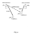
- FIG. 4 is a diagram illustrating an example of a relationship between base stations and terminals in a multi-cell environment.
- the present invention has been made to solve the above problems, and aims at providing a signal mapping method and a communication device for reducing the deterioration of a communication quality caused by an influence of the inter-cell interference occurring under a multi-cell environment.
- the present invention provides a signal mapping method according to claim 1.
- Dependent claims refer to preferred embodiments of the invention.
- a mapping of an error correction encoded signal is changed by a data symbol simultaneously transmitted with a pilot signal, and a data symbol not simultaneously transmitted with the pilot signal.
- a modulation system is changed by the data symbol simultaneously transmitted with the pilot signal, and the data symbol not simultaneously transmitted with the pilot signal.
- a signal mapping method for mapping data signals and pilot signals having a known pattern in each symbol determined by a subcarrier number and a symbol number, or in each symbol determined by a frequency axis and a time axis, in a multicarrier communication system that communicates an encoded signal by using a plurality of subcarriers, the signal mapping method comprising steps of:
- a signal mapping method for mapping data signals and pilot signals having a known pattern in each symbol determined by a subcarrier number and a symbol number, or in each symbol determined by a frequency axis and a time axis, in a multicarrier communication system that communicates an encoded signal by using a plurality of subcarriers, the signal mapping method comprising steps of:
- the signal mapping method and the communication device which can reduce an influence of the deterioration of the communication quality even under an environment in which there are the inter-cell interference in a multicarrier communication system such as an OFDM.
- a signal mapping method and a communication device are applied to a signal that is transmitted from a first radio station to a second radio station.
- the first radio station is called “transmitter station”
- the second radio station is called “receiver station”.
- the signal mapping method and the communication device can be applied to both of signal transmission from the first radio station to the second radio station, and signal transmission from the second radio station to the first radio station.
- each of the first and second radio stations conducts signal processing of both of the transmitter station and the receiver station which will be described below.
- the communication device can include the transmitter station, the receiver station, or both of the transmitter station and the receiver station.
- the fixed station corresponds to the transmitter station
- the mobile station corresponds to the receiver station
- the present invention is applied to a communication from the mobile station to the fixed station
- the mobile station corresponds to the transmitter station
- the fixed station corresponds to the receiver station.
- the present invention is applied to both communications from the fixed station to the mobile station, and from the mobile station to the fixed station, each of the fixed station and the mobile station conducts both signal processing as the transmitter station and the receiver station.
- each of the terminals when a signal produced by application of the present invention is transmitted, each of the terminals operates as the transmitter station, and when the signal produced by application of the present invention is received, each of the terminals operates as the receiver station.
- the embodiments of the present invention will be described with reference to an OFDM system in which respective subcarriers have frequencies orthogonal to each other on a symbol basis, as a multicarrier communication system.
- the present invention is not limited to the OFDM system, but can be applied to any multicarrier systems using the plural subcarriers.
- data referred to as "data symbol” and “transmission data” may include only user data such as speech traffic or image or video traffic, or may include a control signal in addition to the user data.
- a pilot symbol means a signal having a fixed pattern used for estimation of phase and amplitude fluctuation in a channel.
- a signal referred to as "reference signal” corresponds to the pilot signal.
- pilot symbol mapping method an appropriate method can be employed.
- any mappings of the pilot symbols can be employed in which there are a data symbol simultaneously transmitted with the pilot symbol and a data symbol not simultaneously transmitted with the pilot symbol.
- the mapping method may be identical to that of the downlink reference signal disclosed in Non Patent Document 1.
- a likelihood means a value estimated from a receive signal.
- the likelihood means a logarithmic value of a ratio of a probability that the transmit signal is estimated to be 0 and a probability that the transmit signal is estimated to be 1, or an approximate value thereof.
- the likelihood also refers to a value called "log likelihood ratio”.
- FIG. 5 illustrates an example of a schematic diagram of a signal mapping according to an embodiment of the present invention.
- the axis of ordinate represents a subcarrier, that is, frequency
- the axis of abscissa represents an OFDM symbol, that is, a time
- an individual rectangle represents one modulation symbol.
- Respective gray rectangles 202 represent pilot symbols
- hatched rectangles represent data symbols 212 simultaneously transmitted with the pilot symbols
- white rectangles represent other data symbols 201 not simultaneously transmitted with the pilot symbols.
- the signals are selected and mapped so that minimum signals required for decoding the receive signal are mapped in the data symbols 201 not simultaneously transmitted with the pilot symbols with the highest priority, and punctured codes are configured by only signals mapped in the data symbols 201 not simultaneously transmitted with the pilot symbols.
- the signals that can be mapped in the data symbols 201 not simultaneously transmitted with the pilot symbols are M0 bits
- the signals that can be mapped in the data symbols 212 simultaneously transmitted with the pilot symbols are M1 bits
- the transmit signals before error correction encoding are N0 bits
- the signals after the error correction encoding are N1 bits.
- the data mapping is conducted with two slots as one unit by the aid of a QPSK that can communicate two bits per one symbol as a modulation system of each symbol in the symbol mapping of FIG. 5 .
- the number of data symbols 212 simultaneously transmitted with the pilot symbols is 40
- M1 80 is satisfied.
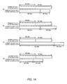
- FIG. 14 is a diagram illustrating an example of a diagram representative of a conditional branch of a signal mapping according to the embodiment of the present invention.
- the signal mapping is conducted according to a relationship of values of M0, M1, N0, and N1 as follows.
- FIG. 7 is a schematic diagram illustrating an encoding block of turbo codes which are one of the systematic codes used in a radio communication.
- signals before encoding 500 are output directly as series of systematic bits 501, and also output as series of parity bits 502 that have been subjected to recursive convolutional encoding through a recursive convolutional encoding block 511, and as series of parity signals 503 that have been subjected to recursive convolutional encoding through a recursive convolutional encoding block 512, after order is converted in a turbo interleaver 510.
- the series of parity bits 502 and 503 may be mapped in the data symbols 201 not simultaneously transmitted with the pilot symbols and the data symbols 212 simultaneously transmitted with the pilot symbols.
- the systematic codes exemplify the turbo codes.
- the same method is applicable even to systematic codes different from the turbo codes, such as LDPC codes.
- a method of configuring the punctured codes different from the above method may be used if decodable punctured codes can be configured. Also, there is no need to use the systematic codes as the error correction codes.
- data can be decoded without using the data symbols 212 simultaneously transmitted with the pilot symbols whose quality is deteriorated by interference derived from the pilot signals of another cell. Therefore, the communication quality can be prevented from being deteriorated even in an environment where inter-cell interference exists.
- FIG. 15 illustrates another example of a schematic diagram of the signal mapping according to the embodiment of the present invention.
- the axis of ordinate represents a subcarrier, that is, frequency
- the axis of abscissa represents an OFDM symbol, that is, a time
- an individual rectangle represents one modulation symbol.
- Gray rectangles represent the pilot symbols 202
- hatched rectangles represent the data symbols 212 simultaneously transmitted with the pilot symbols
- white rectangles represent the other data symbols 201 not simultaneously transmitted with the pilot symbols.
- an area surrounded by a chain line represents a first channel range 221, which represents that the data symbols within the area surrounded by the chain line get together to configure one channel.
- an area surrounded by a broken line represents a channel range 222 in the figure, which represents that the data symbols within the area surrounded by the broken line get together to configure another channel.
- the same signal mapping as the signal mapping of FIG. 5 may be conducted for each channel.
- the first channel range 221 may not conduct the same signal mapping as the signal mapping of FIG. 5 , but may conduct the same signal mapping as the signal mapping of FIG. 5 only in the second channel range 222.
- FIG. 15 illustrates an example of a case in which two channels are mapped within a unit that conducts the data mapping. The same is applied to a case in which three or more channels are mapped.
- FIG. 6 illustrates another example of the schematic diagram of the signal mapping according to the embodiment of the present invention.
- the axis of ordinate represents a subcarrier, that is, frequency
- the axis of abscissa represents an OFDM symbol, that is, a time
- an individual rectangle represents one modulation symbol.
- Gray rectangles represent the pilot symbols 202
- hatched rectangles represent the data symbols 212 simultaneously transmitted with the pilot symbols
- white rectangles represent the other data symbols 201 not simultaneously transmitted with the pilot symbols.
- rectangles marked with x represent no transmission symbols 203 that do not transmit the signals by transmitting the pilot signals by another antenna.
- Vertically-striped rectangles represent data symbols 213 simultaneously transmitted with the no transmission symbols.
- a signal mapping method for the data symbols 212 simultaneously transmitted with the pilot symbols and the data symbols 201 not simultaneously transmitted with the pilot symbols is the same as that in the signal mapping of FIG. 5 .
- the data symbols 213 simultaneously transmitted with no transmission symbols may be treated as the data symbols 212 simultaneously transmitted with the above pilot symbols, or may be treated as the data symbols 201 not simultaneously transmitted with the pilot symbols.
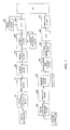
- FIG. 1 is a block diagram representative of signal processing in the communication device (radio station) according to the present invention.
- An error correction encoding block 301 subjects transmit information input by the aid of an error correction code such as a turbo code, a convolutional code, a Reed-Solomon code, or an LDPC code to error correction encoding, and outputs the encoded information to an interleave block 302.
- the error correction encoding block 301 may add the error detection code such as a CRC to the transmit information before the error correction encoding.
- the error correction encoding block 301 may conduct a random process on a signal using, for example, a PN code before or after the error correction encoding.
- the interleave block 302 conducts an interleave process for replacement of a signal order on an input signal, and outputs the signal to a transmit buffer block 303.
- the transmit buffer block 303 accumulates input signals, and outputs the signals to a multiplexing and mapping block 304 according to the amount of information transmitted every unit time.
- plural blocks can be provided in parallel for conducting the processes, or one or the plural blocks can be repetitively used by time multiplexing.
- the multiplexing and mapping block 304 maps the signals in the data symbols, and also maps the pilot signals in the pilot symbols.
- the multiplexing and mapping block 304 maps the input signals and pilot signals in correspondence with the subcarriers and the symbol times for transmission, for plural channels if plural channels are used for communication, and for plural users if communication is conducted for the plural users, and conduct output.
- the multiplexing and mapping block 304 conducts mapping so as to conduct the signal mapping according to the above rule at the output time of the multiplexing and mapping block 304.
- the subcarriers where signals are mapped and the symbol times need to be associated with the output of the error correction encoding block 301. Therefore, the mapping according to the above rule may be provided at any portion therebetween. That is, for example, the error correction encoding block 301 may conduct encoding by the aid of the systematic codes, the interleave block 302 may interleave the systematic bits and parity bits, individually, and the multiplexing and mapping block 304 may allocate those signals to the subcarriers and the symbol times according to the above rule.
- a mapping rule in the multiplexing and mapping block 304 may be fixed, and the interleave block 302 may conduct interleaving according to the above rule in advance in allocating the signals to the subcarriers and the symbol times according to the mapping rule.
- a symbol modulation block 305 modulates the signals allocated to each subcarrier and each symbol time for each subcarrier and each symbol time through a symbol modulation system such as a BPSK, a QPSK, an 8PSK, or a 16QAM.
- An IFFT block 306 aligns the signals input from the symbol modulation block 305 on a frequency axis, and converts the input signals into time domain signals through IFFT computation for outputting.
- a GI insertion block 307 conducts a guard interval insertion process for copying a partial end of the time domain signal after IFFT computation for each IFFT signal processing unit to insert the copied one into a head thereof, as illustrated in a schematic diagram of FIG. 8 .
- the GI insertion block 307 then converts the signal into a signal of a radio frequency bandwidth through an RF block for transmission.
- a timing detection block 408 detects a receive signal timing by a receive signal converted into the baseband bandwidth through the RF block for outputting to an FFT block 406.
- a receive signal timing for example, a cross-correlation value of the receive signal and the fixed pattern signal may be used, or an autocorrelation value of the receive signal per se apart by an IFFT unit may be used.
- the FFT block 406 cuts the signal of the time domain input from the RF block by the IFFT unit by the aid of a receive timing notified from the timing detection block 408, conducts an FFT process on the cut signals, and converts the signals into signals of a frequency domain for outputting.
- a channel estimation block 407 compares a phase and an amplitude of each pilot signal included in the signal input from the FFT block 406 with a phase and an amplitude of each pilot signal that is the transmitted fixed pattern, estimates variations of the phase and the amplitude for each subcarrier and each time according to a comparison result, and notifies a symbol demodulation block 405 of an estimation result.
- the symbol demodulation block 405 compensates fluctuation of the signal input from the FFT block 406 in the channel by the aid of the estimated values of the phase and amplitude fluctuations notified from the channel estimation block 407, demodulates the symbol modulated signal such as the QPSK and the 16 QAM, and derives likelihood for each bit for outputting.
- a signal separate block 404 extracts and separates the signal for each unit of the decoding process which is conducted, for example, for each user and each channel with respect to the likelihood for each bit derived by the symbol demodulation block 405.
- a receiver buffer block 403 holds an output of the signal separate block 404 for each unit of the decoding process.
- the receiver buffer block 403 outputs the signals to a deinterleave block 402.
- the deinterleave block 402 conducts a deinterleave process which is an order conversion corresponding to the reverse conversion of the order conversion conducted in the interleave block 302 during transmission.
- An error correction decoding block 401 conducts a decoding process by the aid of the error correction code used in the error correction encoding block 301, and outputs the decoded signal as receive information. Also, when a random process is conducted before or after the error correction encoding in the error correction encoding block 301 during transmission, a reverse conversion process corresponding to the random process is conducted after or before the decoding process. Also, when the error detection code is added before the error correction encoding in the error correction encoding block 301, the error detection process is conducted after the decoding process, and the error detection result is added to the receive information, and output.
- plural blocks can be provided in parallel for conducting the processes, or one or the plural blocks can be repetitively used by time multiplexing.
- the above flow of signal processing is an example, and if the signal output from the RF block finally has the same form during transmission, and if the signal output from the error correction decoding block 401 has the same form during reception, the flow and order of the signal processing may be changed in any manner.
- the symbol modulation block 305 is disposed after the multiplexing and mapping block 204.
- the symbol modulation block 305 may be disposed immediately after the interleave block 302 so that symbol modulation may be conducted before the signals are accumulated in the transmit buffer block 303.
- the object of the present invention can be also achieved by changing the modulation method as another embodiment.
- a modulation system used in the data symbols 212 simultaneously transmitted with the pilot symbols provides a system high in the error resistance, thereby making it possible to reduce the deterioration of the communication quality caused by interference from the pilot symbols of another cell.
- the error resistance is higher as the modulation system is smaller in the maximum number of transmittable bits per symbol for each modulation system. For that reason, for example, when 64QAM that can transmit information of 6 bits at the maximum per one symbol is used in the data symbols 201 not simultaneously transmitted with the pilot symbols, the object can be achieved by using the 16QAM that can transmit the information of 4 bits at the maximum per one symbol in the data symbols 212 simultaneously transmitted with the pilot symbols, or by using the QPSK that can transmit the information of 2 bits at the maximum per one symbol.
- the object can be achieved by using the modulation system such as the BPSK, the QPSK, or the 8PSK having information only in the phase direction without information in the amplitude direction in the data symbols 212 simultaneously transmitted with the pilot symbols so that a large peak power does not occur for each symbol, in order to reduce the interference with the pilot symbols of another cell.
- the modulation system such as the BPSK, the QPSK, or the 8PSK having information only in the phase direction without information in the amplitude direction in the data symbols 212 simultaneously transmitted with the pilot symbols so that a large peak power does not occur for each symbol, in order to reduce the interference with the pilot symbols of another cell.
- a method of selecting the modulation system for the data symbols 212 simultaneously transmitted with the pilot symbols and the data symbols 201 not simultaneously transmitted with the pilot symbols is the same as the selection of the modulation system in FIG. 5 .
- the data symbols 213 simultaneously transmitted with no transmission symbol may be treated as the data symbols 212 simultaneously transmitted with the pilot symbols, or may be treated as the data symbols 201 not simultaneously transmitted with the pilot symbols.
- the symbol modulation block 305 selects the modulation system different between the data symbols 201 not simultaneously transmitted with the pilot symbols and the data symbols 212 simultaneously transmitted with the pilot symbols. For example, the symbol modulation block 305 selects the modulation system smaller in the maximum number of transmittable bits per one symbol, for the modulation system used in the data symbols 212 simultaneously transmitted with the pilot symbols, as compared with the modulation system used in the data symbols 201 not simultaneously transmitted with the pilot symbols.
- the symbol modulation block 305 selects, as a modulation system used in the data symbols 212 simultaneously transmitted with the pilot symbols, the modulation system such as the BPSK, the QPSK, or the 8PSK having no information in the amplitude system.
- the symbol modulation block 305 may select the modulation system for each channel or each target user, individually, in conducting the signal processing for the plural channels or the plural users.
- the system described in this embodiment can be used, independently, and can be also implemented together with the method described in the first embodiment at the same time.
- the methods described in the first embodiment and the second embodiment can further effectively achieve the object of the present invention by addition of control of the transmission power. That is, with application of one or both of the methods described in the first embodiment and the second embodiment, the transmission power per one symbol of the data symbols 212 simultaneously transmitted with the pilot symbols is made smaller than the transmission power per one symbol of the data symbols 201 not simultaneously transmitted with the pilot symbols, or the transmission power per symbol of the data symbols 212 simultaneously transmitted with the pilot symbols is set to 0, thereby enabling an influence of the inter-cell interference to be reduced.
- the quality in decoding the receive signal including the symbol is deteriorated. Therefore, in combination with the signal mapping described in the first embodiment, the deterioration of the decoding quality can be reduced. Also, the deterioration of the decoding quality can be reduced by reducing the number of bits per symbol in the modulation system used in the data symbols 212 simultaneously transmitted with the pilot symbols as described in the second embodiment.
- the receiver station can demodulate the signal even without having information on whether the transmission power of the data symbols 212 simultaneously transmitted with the pilot symbols is decreased, or not, or how the transmission power of the data symbols 212 simultaneously transmitted with the pilot symbols is decreased, at the transmitter station. Therefore, the transmission power can be easily changed.
- a method of determining the transmission power for the data symbols 212 simultaneously transmitted with the pilot symbols and the data symbols 201 not simultaneously transmitted with the pilot symbols is identical to the method of determining the transmission power of FIG. 5 .
- the data symbols 213 simultaneously transmitted with the no transmission symbol may be treated as the data symbols 212 simultaneously transmitted with the pilot symbols, or may be treated as the data symbols 201 not simultaneously transmitted with the pilot symbols.
- the symbol modulation block 205 reduces the signal amplitude of the data symbols 212 simultaneously transmitted with the pilot symbols more than the signal amplitude of the data symbols 201 not simultaneously transmitted with the pilot symbols.
- the symbol modulation block 205 sets the signal amplitude of the data symbols 212 simultaneously transmitted with the pilot symbols to 0.
- the symbol modulation block 305 may select the signal amplitude for each channel or each target user, individually, in conducting the signal processing for the plural channels or the plural users.
- the likelihood obtained as the demodulation results of the data symbols 212 simultaneously transmitted with the pilot symbols may be reduced or set to 0 in the symbol demodulation block 305.
- a process for reducing the likelihood obtained as the demodulation result there is a method of multiplying the likelihood by a coefficient smaller than 1, for example, 0.5.
- a process of setting the likelihood of the corresponding bits to 0 there is a method of multiplying the likelihood by 0, likewise.
- control of the above third embodiment not only is fixedly conducted, but also can be implemented by triggering the condition.
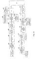
- FIG. 10 is another example of the block diagram representative of the signal processing in the radio station according to this embodiment.
- the block diagram of FIG. 10 is different from the block diagram of FIG. 1 in that a decision block for interference suppression 310 is added, and an input from the decision block for interference suppression to the symbol modulation block 305 is added.
- the respective blocks other than those two points conduct the operation as described in the above embodiments.
- FIG. 11 is an example of a processing flow of the symbol modulation block 305 according to this embodiment.
- the symbol modulation block 305 conducts a process of repeating a process P601 to a process P605 by the number of channels and the number of users.
- a notice from the decision block for interference suppression 310 is decided. If the interference suppression instruction is on, the subsequent processing is advanced to a process P603, and if the interference suppression instruction is off, the subsequent processing is jumped to a process P604.
- a process of reducing the signal amplitude of the data symbols 212 simultaneously transmitted with the pilot is conducted and is advanced to the subsequent process P604.
- the symbol modulation process is conducted by the aid of the modulation system such as the QPSK or the 16QAM for each subcarrier and each symbol time, and the repeating process is completed with process completion of the process P604.
- the decision block for interference suppression 310 decides whether power control for interference suppression is necessary for the signals of each channel and each user, or not, and notifies the symbol modulation block 305 of the interference suppression instruction on or the interference suppression instruction off.
- the decision block for interference suppression 310 sets the interference suppression instruction to on if a self station is a femtocell, for example, according the type of the self station as a condition for decision. Also, the decision block for interference suppression 310 sets the interference suppression instruction to on if a destination station is a femtocell, for example, according the type of a destination station of the signal as another condition for decision.
- the decision block for interference suppression 310 switches between a user of on and a user of off, for example, according the type of a destination user of the signal as still another condition for determination. Further, the decision block for interference suppression 310 sets the interference suppression instruction to on in a case of the best effort type communication, for example, according to QoS of the signal as still another condition for determination. Further, the decision block for interference suppression 310 sets the interference suppression instruction to on when the total transmission power of a channel is large, for example, according to the total amount of transmission power of the channel as still another condition for determination.
- FIG. 12 is another example of a block diagram representative of a signal processing in a radio station according to this embodiment.
- a receiver station according to this embodiment can be configured as illustrated in the block diagram of FIG. 12 .
- the block diagram of FIG. 12 is different from the block diagram of FIG. 10 in that a power decrease judgment block 409 is added, and an input from the power decrease judgment block 409 to the symbol demodulation block 405 is added.
- the respective blocks other than those two points conduct the operation as described with reference to the block diagram of FIG. 10 .
- FIG. 13 is an example of a processing flow of the power decrease judgment block 409 according to this embodiment.
- the power decrease judgment block 409 repeats a process P611 to a process P617 by the number of channels and the number of users. In the repeating process, the power decrease judgment block 409 first determines a power decrease judgment coefficient C in a process P612.
- the power decrease judgment coefficient C is a nonnegative value for judging a power decrease of the data symbols 212 simultaneously transmitted with the pilot symbols at the transmitter station. A possibility that the power decrease is overlooked is decreased more as the coefficient C is smaller. On the other hand, there increases a possibility of misjudgment that the power is decreased although the power is not decreased at the transmitter station.
- the power decrease judgment block 409 derives an average power Pr per symbol of the pilot symbols within the channel in a process P613. In derivation of the average power Pr, the power decrease judgment block 409 may average past values. Then, the power decrease judgment block 409 derives an average power Pd per symbol of the data symbols 212 simultaneously transmitted with the pilot symbols within the channel in a process P614.
- the process P612, the process P613, and the process P614 are described in the stated order. However, because those processes are independent from each other, the processes may be executed in any order.
- the power decrease judgment block 409 compares a product value of the average power Pd and the coefficient C with a value of the average value Pr. As a result of comparison, if the average power Pr is larger, the subsequent process is advanced to a process P616, and in other cases, the subsequent process is jumped to a completion of the repeating process in a process P617.
- the power decrease judgment block 409 indicates a likelihood decrease indication to the symbol demodulation block 405.
- the power decrease judgment block 409 completes the repeating process upon completion of the process P616 or according to a result of the branch in the process P615.
- the symbol demodulation block 405 when the symbol demodulation block 405 is notified of the likelihood decrease instruction from the power decrease judgment block 409, the symbol demodulation block 405 decreases the likelihood of the bits corresponding to the data symbols 212 simultaneously transmitted with the pilot symbols of an appropriate channel and user, or sets the likelihood to 0.
- the symbol demodulation block 405 multiplies the likelihood by a coefficient 1.
- the symbol demodulation block 405 When the symbol demodulation block 405 is not notified of the likelihood decrease instruction from the power decrease judgment block 409, the symbol demodulation block 405 multiplies the likelihood by the coefficient smaller than 1, for example, 0.5. As a process of setting the likelihood of the corresponding bits to 0, there is a method in which when the symbol demodulation block 405 is notified of the likelihood decrease instruction from the power decrease judgment block 409 likewise, the symbol demodulation block 405 multiplies the likelihood by 0.
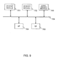
- FIG. 9 is a schematic diagram of a transceiver mounted example mainly including a CPU and a DSP.
- a block 701 is a CPU/DSP modulate, and conducts the signal processing computation and controls the signal processing as described in the above respective embodiments.
- a block 702 is a memory module, and holds the transmit signal and the receive signal during the processing and before and after the processing, and a table used for the signal processing.
- a block 703 is a logic circuit module, and conducts the signal processing computation and controls the signal processing as described in the above respective embodiments as with the CPU/DSP 701.
- a block 704 is an interface module, and inputs and outputs the control signal, the transmit signal before the signal processing, and the receive signal after the signal processing.
- a block 705 is an RF module, which converts the transmit signal into a signal of a radio frequency bandwidth, and transmits the converted signal via an antenna, and converts the receive signal received through the antenna into a signal of the baseband bandwidth.
- a bus 706 connects the above respective modules to each other.
- Each of the signal processing computation and the signal processing control in the respective processing blocks described in the first to fourth embodiments is conducted with the use of one or both of a program in the CPU/DSP module 701 and a computing circuit in the logic circuit module 703, and also the memory module 702 if required.
- FIG. 9 illustrates a simplest embodiment having the respective modules one by one.
- the number of each of the module and the bus does not always need to be single.
- plural CPU/DSP modules 701 may be provided, or plural buses 706 may be provided.
- the plural buses 706 there is no need to always connect all the buses to all the modules.
- the present invention can be applied to various multicarrier communication systems and modulation systems other than the above-mentioned systems and methods.
Landscapes
- Engineering & Computer Science (AREA)
- Signal Processing (AREA)
- Computer Networks & Wireless Communication (AREA)
- Mobile Radio Communication Systems (AREA)
Applications Claiming Priority (2)
| Application Number | Priority Date | Filing Date | Title |
|---|---|---|---|
| JP2008325929 | 2008-12-22 | ||
| PCT/JP2009/071130 WO2010073987A1 (ja) | 2008-12-22 | 2009-12-18 | 信号配置方法及び通信装置 |
Publications (3)
| Publication Number | Publication Date |
|---|---|
| EP2381602A1 EP2381602A1 (en) | 2011-10-26 |
| EP2381602A4 EP2381602A4 (en) | 2014-04-30 |
| EP2381602B1 true EP2381602B1 (en) | 2015-12-16 |
Family
ID=42287597
Family Applications (1)
| Application Number | Title | Priority Date | Filing Date |
|---|---|---|---|
| EP09834788.3A Not-in-force EP2381602B1 (en) | 2008-12-22 | 2009-12-18 | Method of positioning of signal |
Country Status (4)
| Country | Link |
|---|---|
| US (1) | US8630313B2 (ja) |
| EP (1) | EP2381602B1 (ja) |
| JP (1) | JP5377516B2 (ja) |
| WO (1) | WO2010073987A1 (ja) |
Families Citing this family (7)
| Publication number | Priority date | Publication date | Assignee | Title |
|---|---|---|---|---|
| US8937875B2 (en) | 2009-03-16 | 2015-01-20 | Panasonic Intellectual Property Corporation Of America | Radio reception apparatus, radio transmission apparatus, and radio communication method |
| JP5280384B2 (ja) * | 2010-01-28 | 2013-09-04 | Kddi株式会社 | 無線基地局装置及び無線通信方法 |
| JP2012034211A (ja) * | 2010-07-30 | 2012-02-16 | Panasonic Corp | 基地局装置及び送信電力制御方法 |
| EP2690812B1 (en) * | 2012-07-25 | 2016-02-24 | Mitsubishi Electric R&D Centre Europe B.V. | Method and device for performing channel estimation and equalization for an optical OFDM signal |
| JP6848879B2 (ja) * | 2015-11-19 | 2021-03-24 | ソニー株式会社 | 装置、方法及びプログラム |
| US10454659B2 (en) | 2017-02-28 | 2019-10-22 | Qualcomm Incorporated | Narrowband time-division duplex frame structure for narrowband communications |
| CN110838889B (zh) * | 2018-08-16 | 2022-06-24 | 海能达通信股份有限公司 | 编码方法、解码方法、发送终端和接收终端 |
Family Cites Families (12)
| Publication number | Priority date | Publication date | Assignee | Title |
|---|---|---|---|---|
| US6947748B2 (en) * | 2000-12-15 | 2005-09-20 | Adaptix, Inc. | OFDMA with adaptive subcarrier-cluster configuration and selective loading |
| JP4323985B2 (ja) * | 2003-08-07 | 2009-09-02 | パナソニック株式会社 | 無線送信装置及び無線送信方法 |
| JP4041087B2 (ja) | 2004-03-31 | 2008-01-30 | 株式会社東芝 | 通信装置および通信方法 |
| US7457231B2 (en) * | 2004-05-04 | 2008-11-25 | Qualcomm Incorporated | Staggered pilot transmission for channel estimation and time tracking |
| KR100698770B1 (ko) * | 2005-03-09 | 2007-03-23 | 삼성전자주식회사 | 광대역 무선통신시스템에서 시공간 부호화 데이터의 부반송파 사상 장치 및 방법 |
| US8483295B2 (en) | 2006-05-31 | 2013-07-09 | Hitachi, Ltd. | Encoded signal arrangement method in multi-carrier communication and communication device |
| JP2007329588A (ja) * | 2006-06-06 | 2007-12-20 | Fujitsu Ltd | 送信機及び送信方法 |
| JP5159274B2 (ja) | 2006-11-30 | 2013-03-06 | パナソニック株式会社 | 無線送信装置及び無線送信方法 |
| JP4640844B2 (ja) | 2007-01-09 | 2011-03-02 | 株式会社エヌ・ティ・ティ・ドコモ | 送信装置、送信方法及び通信システム |
| US8315660B2 (en) * | 2007-02-14 | 2012-11-20 | Qualcomm Incorporated | User power offset estimation using dedicated pilot tones for OFDMA |
| US8411732B2 (en) * | 2007-03-21 | 2013-04-02 | Qualcomm Incorporated | Fast square root algorithm for MIMO equalization |
| US7804893B2 (en) * | 2007-04-26 | 2010-09-28 | Broadcom Corporation | Feedback of reinterleaved correctly decoded data block to decoder for use in additional channel decoding operations of channel coded word containing data block |
-
2009
- 2009-12-18 EP EP09834788.3A patent/EP2381602B1/en not_active Not-in-force
- 2009-12-18 US US13/141,308 patent/US8630313B2/en not_active Expired - Fee Related
- 2009-12-18 JP JP2010544036A patent/JP5377516B2/ja not_active Expired - Fee Related
- 2009-12-18 WO PCT/JP2009/071130 patent/WO2010073987A1/ja active Application Filing
Also Published As
| Publication number | Publication date |
|---|---|
| US20110255519A1 (en) | 2011-10-20 |
| JPWO2010073987A1 (ja) | 2012-06-14 |
| WO2010073987A1 (ja) | 2010-07-01 |
| EP2381602A1 (en) | 2011-10-26 |
| US8630313B2 (en) | 2014-01-14 |
| EP2381602A4 (en) | 2014-04-30 |
| JP5377516B2 (ja) | 2013-12-25 |
Similar Documents
| Publication | Publication Date | Title |
|---|---|---|
| US10819411B2 (en) | Integrated circuit for CQI reporting in wireless communication | |
| RU2444132C2 (ru) | Базовая станция и способ передачи сигнала | |
| KR100996080B1 (ko) | 직교 주파수 분할 다중 방식을 사용하는 통신 시스템에서적응적 변조 및 코딩 제어 장치 및 방법 | |
| EP1811734B1 (en) | Method and apparatus for controlling transmission and reception of dedicated pilots according to MCS level in a wireless communication system | |
| EP1775901B1 (en) | Radio transmission device and radio reception device | |
| EP1903692B1 (en) | Multicarrier communication system, multicarrier communication apparatus and cqi reporting method | |
| KR100967774B1 (ko) | 제어 채널 송신 및 수신을 위한 방법 및 장치 | |
| KR100881967B1 (ko) | 단반송파 주파수 분할 다중접속 시스템에서 역방향 정보들의 송수신 방법 및 장치 | |
| EP3306847A2 (en) | Communication apparatus, communication system, and communication method | |
| EP2381602B1 (en) | Method of positioning of signal | |
| EP1557994A2 (en) | Modulating and coding apparatus and method in a high-rate wireless data communication system | |
| US9241334B2 (en) | Wireless reception device, wireless transmission device, and wireless communication method | |
| KR20050064156A (ko) | 직교 주파수 분할 다중 접속 시스템에서 주파수재사용율을 고려한 적응적 부채널 할당 장치 및 방법 | |
| KR20100044778A (ko) | 유저장치, 기지국장치 및 채널상태정보 통신방법 | |
| US8483295B2 (en) | Encoded signal arrangement method in multi-carrier communication and communication device | |
| WO2013031119A1 (ja) | Sc-fdma送信装置及び送信方法 | |
| EP2107700A1 (en) | Mobile communication system, terminal, base station device, and data communication method | |
| KR20070077008A (ko) | 셀룰러 통신 시스템에서 낮은 변조 및 코드율 레벨 사용시전용 파일롯의 전송 방법 및 장치 | |
| KR20050005993A (ko) | 직교 주파수 분할 다중 방식을 사용하는 이동 통신시스템에서 적응적 변조 및 코딩 방식 제어 장치 및 방법 | |
| CN112771824A (zh) | 基站以及终端装置 | |
| KR20070050118A (ko) | Ofdma 이동 통신 시스템의 채널할당방법 및 그 장치 |
Legal Events
| Date | Code | Title | Description |
|---|---|---|---|
| PUAI | Public reference made under article 153(3) epc to a published international application that has entered the european phase |
Free format text: ORIGINAL CODE: 0009012 |
|
| 17P | Request for examination filed |
Effective date: 20110722 |
|
| AK | Designated contracting states |
Kind code of ref document: A1 Designated state(s): AT BE BG CH CY CZ DE DK EE ES FI FR GB GR HR HU IE IS IT LI LT LU LV MC MK MT NL NO PL PT RO SE SI SK SM TR |
|
| DAX | Request for extension of the european patent (deleted) | ||
| A4 | Supplementary search report drawn up and despatched |
Effective date: 20140331 |
|
| RIC1 | Information provided on ipc code assigned before grant |
Ipc: H04L 5/00 20060101ALI20140325BHEP Ipc: H04L 1/00 20060101ALI20140325BHEP Ipc: H04W 72/04 20090101ALI20140325BHEP Ipc: H04J 11/00 20060101AFI20140325BHEP |
|
| GRAP | Despatch of communication of intention to grant a patent |
Free format text: ORIGINAL CODE: EPIDOSNIGR1 |
|
| INTG | Intention to grant announced |
Effective date: 20150708 |
|
| GRAS | Grant fee paid |
Free format text: ORIGINAL CODE: EPIDOSNIGR3 |
|
| GRAA | (expected) grant |
Free format text: ORIGINAL CODE: 0009210 |
|
| AK | Designated contracting states |
Kind code of ref document: B1 Designated state(s): AT BE BG CH CY CZ DE DK EE ES FI FR GB GR HR HU IE IS IT LI LT LU LV MC MK MT NL NO PL PT RO SE SI SK SM TR |
|
| REG | Reference to a national code |
Ref country code: GB Ref legal event code: FG4D |
|
| REG | Reference to a national code |
Ref country code: CH Ref legal event code: EP |
|
| REG | Reference to a national code |
Ref country code: IE Ref legal event code: FG4D |
|
| REG | Reference to a national code |
Ref country code: AT Ref legal event code: REF Ref document number: 766012 Country of ref document: AT Kind code of ref document: T Effective date: 20160115 |
|
| REG | Reference to a national code |
Ref country code: FR Ref legal event code: PLFP Year of fee payment: 7 |
|
| REG | Reference to a national code |
Ref country code: DE Ref legal event code: R096 Ref document number: 602009035313 Country of ref document: DE |
|
| REG | Reference to a national code |
Ref country code: NL Ref legal event code: MP Effective date: 20151216 |
|
| REG | Reference to a national code |
Ref country code: LT Ref legal event code: MG4D |
|
| PG25 | Lapsed in a contracting state [announced via postgrant information from national office to epo] |
Ref country code: NO Free format text: LAPSE BECAUSE OF FAILURE TO SUBMIT A TRANSLATION OF THE DESCRIPTION OR TO PAY THE FEE WITHIN THE PRESCRIBED TIME-LIMIT Effective date: 20160316 Ref country code: LT Free format text: LAPSE BECAUSE OF FAILURE TO SUBMIT A TRANSLATION OF THE DESCRIPTION OR TO PAY THE FEE WITHIN THE PRESCRIBED TIME-LIMIT Effective date: 20151216 Ref country code: HR Free format text: LAPSE BECAUSE OF FAILURE TO SUBMIT A TRANSLATION OF THE DESCRIPTION OR TO PAY THE FEE WITHIN THE PRESCRIBED TIME-LIMIT Effective date: 20151216 |
|
| PGFP | Annual fee paid to national office [announced via postgrant information from national office to epo] |
Ref country code: DE Payment date: 20151231 Year of fee payment: 7 |
|
| REG | Reference to a national code |
Ref country code: AT Ref legal event code: MK05 Ref document number: 766012 Country of ref document: AT Kind code of ref document: T Effective date: 20151216 |
|
| PG25 | Lapsed in a contracting state [announced via postgrant information from national office to epo] |
Ref country code: FI Free format text: LAPSE BECAUSE OF FAILURE TO SUBMIT A TRANSLATION OF THE DESCRIPTION OR TO PAY THE FEE WITHIN THE PRESCRIBED TIME-LIMIT Effective date: 20151216 Ref country code: SE Free format text: LAPSE BECAUSE OF FAILURE TO SUBMIT A TRANSLATION OF THE DESCRIPTION OR TO PAY THE FEE WITHIN THE PRESCRIBED TIME-LIMIT Effective date: 20151216 Ref country code: GR Free format text: LAPSE BECAUSE OF FAILURE TO SUBMIT A TRANSLATION OF THE DESCRIPTION OR TO PAY THE FEE WITHIN THE PRESCRIBED TIME-LIMIT Effective date: 20160317 Ref country code: BE Free format text: LAPSE BECAUSE OF NON-PAYMENT OF DUE FEES Effective date: 20151231 Ref country code: NL Free format text: LAPSE BECAUSE OF FAILURE TO SUBMIT A TRANSLATION OF THE DESCRIPTION OR TO PAY THE FEE WITHIN THE PRESCRIBED TIME-LIMIT Effective date: 20151216 Ref country code: LV Free format text: LAPSE BECAUSE OF FAILURE TO SUBMIT A TRANSLATION OF THE DESCRIPTION OR TO PAY THE FEE WITHIN THE PRESCRIBED TIME-LIMIT Effective date: 20151216 |
|
| PGFP | Annual fee paid to national office [announced via postgrant information from national office to epo] |
Ref country code: GB Payment date: 20160128 Year of fee payment: 7 Ref country code: FR Payment date: 20160121 Year of fee payment: 7 |
|
| PG25 | Lapsed in a contracting state [announced via postgrant information from national office to epo] |
Ref country code: ES Free format text: LAPSE BECAUSE OF FAILURE TO SUBMIT A TRANSLATION OF THE DESCRIPTION OR TO PAY THE FEE WITHIN THE PRESCRIBED TIME-LIMIT Effective date: 20151216 Ref country code: CZ Free format text: LAPSE BECAUSE OF FAILURE TO SUBMIT A TRANSLATION OF THE DESCRIPTION OR TO PAY THE FEE WITHIN THE PRESCRIBED TIME-LIMIT Effective date: 20151216 Ref country code: IT Free format text: LAPSE BECAUSE OF FAILURE TO SUBMIT A TRANSLATION OF THE DESCRIPTION OR TO PAY THE FEE WITHIN THE PRESCRIBED TIME-LIMIT Effective date: 20151216 |
|
| REG | Reference to a national code |
Ref country code: CH Ref legal event code: PL |
|
| PG25 | Lapsed in a contracting state [announced via postgrant information from national office to epo] |
Ref country code: SM Free format text: LAPSE BECAUSE OF FAILURE TO SUBMIT A TRANSLATION OF THE DESCRIPTION OR TO PAY THE FEE WITHIN THE PRESCRIBED TIME-LIMIT Effective date: 20151216 Ref country code: RO Free format text: LAPSE BECAUSE OF FAILURE TO SUBMIT A TRANSLATION OF THE DESCRIPTION OR TO PAY THE FEE WITHIN THE PRESCRIBED TIME-LIMIT Effective date: 20151216 Ref country code: AT Free format text: LAPSE BECAUSE OF FAILURE TO SUBMIT A TRANSLATION OF THE DESCRIPTION OR TO PAY THE FEE WITHIN THE PRESCRIBED TIME-LIMIT Effective date: 20151216 Ref country code: SK Free format text: LAPSE BECAUSE OF FAILURE TO SUBMIT A TRANSLATION OF THE DESCRIPTION OR TO PAY THE FEE WITHIN THE PRESCRIBED TIME-LIMIT Effective date: 20151216 Ref country code: PT Free format text: LAPSE BECAUSE OF FAILURE TO SUBMIT A TRANSLATION OF THE DESCRIPTION OR TO PAY THE FEE WITHIN THE PRESCRIBED TIME-LIMIT Effective date: 20160418 Ref country code: EE Free format text: LAPSE BECAUSE OF FAILURE TO SUBMIT A TRANSLATION OF THE DESCRIPTION OR TO PAY THE FEE WITHIN THE PRESCRIBED TIME-LIMIT Effective date: 20151216 Ref country code: IS Free format text: LAPSE BECAUSE OF FAILURE TO SUBMIT A TRANSLATION OF THE DESCRIPTION OR TO PAY THE FEE WITHIN THE PRESCRIBED TIME-LIMIT Effective date: 20160416 |
|
| REG | Reference to a national code |
Ref country code: DE Ref legal event code: R097 Ref document number: 602009035313 Country of ref document: DE |
|
| REG | Reference to a national code |
Ref country code: IE Ref legal event code: MM4A |
|
| PG25 | Lapsed in a contracting state [announced via postgrant information from national office to epo] |
Ref country code: MC Free format text: LAPSE BECAUSE OF FAILURE TO SUBMIT A TRANSLATION OF THE DESCRIPTION OR TO PAY THE FEE WITHIN THE PRESCRIBED TIME-LIMIT Effective date: 20151216 |
|
| PLBE | No opposition filed within time limit |
Free format text: ORIGINAL CODE: 0009261 |
|
| STAA | Information on the status of an ep patent application or granted ep patent |
Free format text: STATUS: NO OPPOSITION FILED WITHIN TIME LIMIT |
|
| PG25 | Lapsed in a contracting state [announced via postgrant information from national office to epo] |
Ref country code: LI Free format text: LAPSE BECAUSE OF NON-PAYMENT OF DUE FEES Effective date: 20151231 Ref country code: DK Free format text: LAPSE BECAUSE OF FAILURE TO SUBMIT A TRANSLATION OF THE DESCRIPTION OR TO PAY THE FEE WITHIN THE PRESCRIBED TIME-LIMIT Effective date: 20151216 Ref country code: PL Free format text: LAPSE BECAUSE OF FAILURE TO SUBMIT A TRANSLATION OF THE DESCRIPTION OR TO PAY THE FEE WITHIN THE PRESCRIBED TIME-LIMIT Effective date: 20151216 Ref country code: IE Free format text: LAPSE BECAUSE OF NON-PAYMENT OF DUE FEES Effective date: 20151218 Ref country code: CH Free format text: LAPSE BECAUSE OF NON-PAYMENT OF DUE FEES Effective date: 20151231 |
|
| 26N | No opposition filed |
Effective date: 20160919 |
|
| PG25 | Lapsed in a contracting state [announced via postgrant information from national office to epo] |
Ref country code: BE Free format text: LAPSE BECAUSE OF FAILURE TO SUBMIT A TRANSLATION OF THE DESCRIPTION OR TO PAY THE FEE WITHIN THE PRESCRIBED TIME-LIMIT Effective date: 20151216 |
|
| PG25 | Lapsed in a contracting state [announced via postgrant information from national office to epo] |
Ref country code: SI Free format text: LAPSE BECAUSE OF FAILURE TO SUBMIT A TRANSLATION OF THE DESCRIPTION OR TO PAY THE FEE WITHIN THE PRESCRIBED TIME-LIMIT Effective date: 20151216 |
|
| PG25 | Lapsed in a contracting state [announced via postgrant information from national office to epo] |
Ref country code: HU Free format text: LAPSE BECAUSE OF FAILURE TO SUBMIT A TRANSLATION OF THE DESCRIPTION OR TO PAY THE FEE WITHIN THE PRESCRIBED TIME-LIMIT; INVALID AB INITIO Effective date: 20091218 Ref country code: BG Free format text: LAPSE BECAUSE OF FAILURE TO SUBMIT A TRANSLATION OF THE DESCRIPTION OR TO PAY THE FEE WITHIN THE PRESCRIBED TIME-LIMIT Effective date: 20151216 |
|
| PG25 | Lapsed in a contracting state [announced via postgrant information from national office to epo] |
Ref country code: CY Free format text: LAPSE BECAUSE OF FAILURE TO SUBMIT A TRANSLATION OF THE DESCRIPTION OR TO PAY THE FEE WITHIN THE PRESCRIBED TIME-LIMIT Effective date: 20151216 |
|
| REG | Reference to a national code |
Ref country code: DE Ref legal event code: R119 Ref document number: 602009035313 Country of ref document: DE |
|
| GBPC | Gb: european patent ceased through non-payment of renewal fee |
Effective date: 20161218 |
|
| PG25 | Lapsed in a contracting state [announced via postgrant information from national office to epo] |
Ref country code: MT Free format text: LAPSE BECAUSE OF FAILURE TO SUBMIT A TRANSLATION OF THE DESCRIPTION OR TO PAY THE FEE WITHIN THE PRESCRIBED TIME-LIMIT Effective date: 20151216 Ref country code: TR Free format text: LAPSE BECAUSE OF FAILURE TO SUBMIT A TRANSLATION OF THE DESCRIPTION OR TO PAY THE FEE WITHIN THE PRESCRIBED TIME-LIMIT Effective date: 20151216 |
|
| REG | Reference to a national code |
Ref country code: FR Ref legal event code: ST Effective date: 20170831 |
|
| PG25 | Lapsed in a contracting state [announced via postgrant information from national office to epo] |
Ref country code: FR Free format text: LAPSE BECAUSE OF NON-PAYMENT OF DUE FEES Effective date: 20170102 |
|
| PG25 | Lapsed in a contracting state [announced via postgrant information from national office to epo] |
Ref country code: DE Free format text: LAPSE BECAUSE OF NON-PAYMENT OF DUE FEES Effective date: 20170701 Ref country code: GB Free format text: LAPSE BECAUSE OF NON-PAYMENT OF DUE FEES Effective date: 20161218 Ref country code: LU Free format text: LAPSE BECAUSE OF NON-PAYMENT OF DUE FEES Effective date: 20151218 |
|
| PG25 | Lapsed in a contracting state [announced via postgrant information from national office to epo] |
Ref country code: MK Free format text: LAPSE BECAUSE OF FAILURE TO SUBMIT A TRANSLATION OF THE DESCRIPTION OR TO PAY THE FEE WITHIN THE PRESCRIBED TIME-LIMIT Effective date: 20151216 |