EP2381069B1 - Installation de turbine à gaz - Google Patents
Installation de turbine à gaz Download PDFInfo
- Publication number
- EP2381069B1 EP2381069B1 EP09838765.7A EP09838765A EP2381069B1 EP 2381069 B1 EP2381069 B1 EP 2381069B1 EP 09838765 A EP09838765 A EP 09838765A EP 2381069 B1 EP2381069 B1 EP 2381069B1
- Authority
- EP
- European Patent Office
- Prior art keywords
- flow path
- air
- stage
- cooling
- cooling air
- Prior art date
- Legal status (The legal status is an assumption and is not a legal conclusion. Google has not performed a legal analysis and makes no representation as to the accuracy of the status listed.)
- Active
Links
Images

Classifications
-
- F—MECHANICAL ENGINEERING; LIGHTING; HEATING; WEAPONS; BLASTING
- F01—MACHINES OR ENGINES IN GENERAL; ENGINE PLANTS IN GENERAL; STEAM ENGINES
- F01D—NON-POSITIVE DISPLACEMENT MACHINES OR ENGINES, e.g. STEAM TURBINES
- F01D11/00—Preventing or minimising internal leakage of working-fluid, e.g. between stages
- F01D11/08—Preventing or minimising internal leakage of working-fluid, e.g. between stages for sealing space between rotor blade tips and stator
- F01D11/14—Adjusting or regulating tip-clearance, i.e. distance between rotor-blade tips and stator casing
- F01D11/20—Actively adjusting tip-clearance
- F01D11/24—Actively adjusting tip-clearance by selectively cooling-heating stator or rotor components
-
- F—MECHANICAL ENGINEERING; LIGHTING; HEATING; WEAPONS; BLASTING
- F01—MACHINES OR ENGINES IN GENERAL; ENGINE PLANTS IN GENERAL; STEAM ENGINES
- F01D—NON-POSITIVE DISPLACEMENT MACHINES OR ENGINES, e.g. STEAM TURBINES
- F01D9/00—Stators
- F01D9/02—Nozzles; Nozzle boxes; Stator blades; Guide conduits, e.g. individual nozzles
- F01D9/04—Nozzles; Nozzle boxes; Stator blades; Guide conduits, e.g. individual nozzles forming ring or sector
- F01D9/041—Nozzles; Nozzle boxes; Stator blades; Guide conduits, e.g. individual nozzles forming ring or sector using blades
-
- F—MECHANICAL ENGINEERING; LIGHTING; HEATING; WEAPONS; BLASTING
- F02—COMBUSTION ENGINES; HOT-GAS OR COMBUSTION-PRODUCT ENGINE PLANTS
- F02C—GAS-TURBINE PLANTS; AIR INTAKES FOR JET-PROPULSION PLANTS; CONTROLLING FUEL SUPPLY IN AIR-BREATHING JET-PROPULSION PLANTS
- F02C7/00—Features, components parts, details or accessories, not provided for in, or of interest apart form groups F02C1/00 - F02C6/00; Air intakes for jet-propulsion plants
- F02C7/12—Cooling of plants
- F02C7/14—Cooling of plants of fluids in the plant, e.g. lubricant or fuel
- F02C7/141—Cooling of plants of fluids in the plant, e.g. lubricant or fuel of working fluid
- F02C7/143—Cooling of plants of fluids in the plant, e.g. lubricant or fuel of working fluid before or between the compressor stages
-
- F—MECHANICAL ENGINEERING; LIGHTING; HEATING; WEAPONS; BLASTING
- F02—COMBUSTION ENGINES; HOT-GAS OR COMBUSTION-PRODUCT ENGINE PLANTS
- F02C—GAS-TURBINE PLANTS; AIR INTAKES FOR JET-PROPULSION PLANTS; CONTROLLING FUEL SUPPLY IN AIR-BREATHING JET-PROPULSION PLANTS
- F02C7/00—Features, components parts, details or accessories, not provided for in, or of interest apart form groups F02C1/00 - F02C6/00; Air intakes for jet-propulsion plants
- F02C7/12—Cooling of plants
- F02C7/16—Cooling of plants characterised by cooling medium
- F02C7/18—Cooling of plants characterised by cooling medium the medium being gaseous, e.g. air
-
- F—MECHANICAL ENGINEERING; LIGHTING; HEATING; WEAPONS; BLASTING
- F02—COMBUSTION ENGINES; HOT-GAS OR COMBUSTION-PRODUCT ENGINE PLANTS
- F02C—GAS-TURBINE PLANTS; AIR INTAKES FOR JET-PROPULSION PLANTS; CONTROLLING FUEL SUPPLY IN AIR-BREATHING JET-PROPULSION PLANTS
- F02C7/00—Features, components parts, details or accessories, not provided for in, or of interest apart form groups F02C1/00 - F02C6/00; Air intakes for jet-propulsion plants
- F02C7/28—Arrangement of seals
-
- F—MECHANICAL ENGINEERING; LIGHTING; HEATING; WEAPONS; BLASTING
- F02—COMBUSTION ENGINES; HOT-GAS OR COMBUSTION-PRODUCT ENGINE PLANTS
- F02C—GAS-TURBINE PLANTS; AIR INTAKES FOR JET-PROPULSION PLANTS; CONTROLLING FUEL SUPPLY IN AIR-BREATHING JET-PROPULSION PLANTS
- F02C9/00—Controlling gas-turbine plants; Controlling fuel supply in air- breathing jet-propulsion plants
- F02C9/16—Control of working fluid flow
- F02C9/18—Control of working fluid flow by bleeding, bypassing or acting on variable working fluid interconnections between turbines or compressors or their stages
-
- F—MECHANICAL ENGINEERING; LIGHTING; HEATING; WEAPONS; BLASTING
- F05—INDEXING SCHEMES RELATING TO ENGINES OR PUMPS IN VARIOUS SUBCLASSES OF CLASSES F01-F04
- F05D—INDEXING SCHEME FOR ASPECTS RELATING TO NON-POSITIVE-DISPLACEMENT MACHINES OR ENGINES, GAS-TURBINES OR JET-PROPULSION PLANTS
- F05D2240/00—Components
- F05D2240/10—Stators
- F05D2240/11—Shroud seal segments
Definitions
- the present invention relates to gas turbine plants in which tip clearance control of first-stage turbine rotor blades can be performed.
- Tip clearance in a gas turbine varies depending on the expansion and contraction of rotation-side structural members and stationary-side structural members due to the difference between the temperature during start-up and that during rated operation, and by the centrifugal extension thereof due to the rotation. That is, the variation in the tip clearance is influenced by the temperature at the outlet of a compressor and the temperature of combustion gas, making the clearance of first-stage turbine rotor blades particularly tight.
- ACC active clearance control
- clearance control using steam is performed to increase or decrease the tip clearance of the first-stage turbine rotor blades during operation. More specifically, the clearance is controlled through control of the thermal expansion by heating the blade ring with steam introduced from outside the gas turbine during start-up of the gas turbine and by cooling the blade ring during load operation.
- an ACC blade ring has, therein, a steam path for heating and cooling.
- the amount of expansion of the blade ring that may affect the tip clearance is determined by the relationship between the discharge temperature of the compressor and the steam temperature, whereby the amount of thermal expansion of the blade ring can be adjusted. Accordingly, because the tip clearance is increased by heating with steam during start-up and is reduced by cooling with relatively low-temperature steam during load operation, the tip clearance can be adjusted according to the operating conditions (for example, see JP 3825279B ).
- a gas turbine in which cooling means that cools air for cooling turbine stator blades is provided, and the air cooled by this cooling means is supplied to the turbine stator blades, whereby the amount of discharged air introduced from the air compressor as the air for cooling the turbine stator blades and the amount of air bled from an interstage are reduced to improve the thermal efficiency (for example, see JP Hei-7-54669A ).
- the conventional ACC has a problem in that there are operational limitations, because steam has to be flowed through the blade ring, which requires waiting until the steam to be used meets certain conditions. Accordingly, gas turbine plants are required to solve this problem and improve the working efficiency of ACC.
- the present invention has been made in view of the above-described circumstances, and an object thereof is to provide a gas turbine plant in which active clearance control (ACC) for ensuring the tip clearance of the first-stage turbine rotor blades required during start-up and for achieving the minimum tip clearance during load operation (rated operation) can be performed.
- active clearance control ACC
- US 2005/0076649A discloses a blade tip clearance control for a turbine engine including an air system that supplies, during a transient operational condition, compressor exit air extracted from the combustor shell of the turbine engine through a path including a heat exchanger in order to reduce the temperature of the compressor exit air before this cooled compressor exit air is supplied to the rotor blades and rotor discs.
- a gas turbine plant of the present invention includes a cooler in an air system used for cooling second-stage turbine stator blades.
- a first-stage segmented ring and a second-stage segmented ring that oppose tips of first-stage turbine rotor blades and second-stage turbine rotor blades are supported by the same blade ring, and a cooling-air for the second-stage turbine stator blades forms a cooling air flow cooling the blade ring, to control thermal expansion of the blade ring and to control the clearance with respect to the tips.
- the first-stage segmented ring and the second-stage segmented ring that oppose the tips of the first-stage turbine rotor blades and the second-stage turbine rotor blades are supported by the same blade ring, and the cooling-air for the second-stage turbine stator blades forms a cooling air flow cooling the blade ring, to control thermal expansion of the blade ring and to control the clearance with respect to the tips.
- active clearance control for reducing the tip clearance becomes possible.
- switching means is provided in the flow path for supplying the cooling air for the second-stage stator blades to allow the cooling air to bypass the cooler during start-up and to allow the cooling air to pass through the cooler during load operation, so that the flow path is switched between different flow paths during start-up and during load operation. That is, in the above-described invention, although the conventional cooling air may be used as the cooling air, by switching the flow path between different flow paths during start-up, in which the cooling air bypasses the cooler, and during load operation, in which the cooling air passes through the cooler, the thermal expansion of the blade ring can be more effectively controlled.
- high-pressure bleed air from a compressor is introduced as the cooling air, the flow path bypassing the cooler be selected during start-up, and the flow path passing through the cooler be selected during load operation. That is, it becomes possible to perform active clearance control for ensuring the tip clearance of the first-stage turbine rotor blades by using high-temperature cooling air during start-up and for reducing the tip clearance by using low-temperature cooling air that has passed through the cooler during load operation.
- the switching means that allows high-temperature compressed air introduced from an outlet of the compressor to be used as the cooling air during start-up and that allows the high-pressure bleed air to be introduced and used as the cooling air during load operation is provided, so that the flow path is switched between different flow paths during start-up and during load operation. That is, in the above-described invention, although the conventional cooling air may be used as the cooling air, a more effective method is that high-temperature compressed air introduced from the compressor outlet is used as the cooling air during start-up, and the cooling air is used during load operation.
- This gas turbine plant includes the air system used to cool the second-stage turbine stator blades, and the first-stage segmented ring and the second-stage segmented ring that oppose the tips of first-stage turbine rotor blades and second-stage turbine rotor blades are supported by the same blade ring member.
- the cooling-air for the second-stage turbine stator blades forms a cooling air flow cooling the blade ring member, and the flow path switching means for the cooling air is provided in the cooling-air flow path to switch the flow path used during start-up, in which high-temperature compressed air introduced from the compressor outlet is used as the cooling air, and the flow path used during load operation, in which high-pressure bleed air introduced from the high-pressure stage of the compressor is used as the cooling air.
- the metal temperature of the blade ring can be reduced.
- active clearance control is enabled by switching the cooling air used during start-up and that used during load operation, it is possible to perform a heating operation by raising the temperature of the cooling air and ensure the tip clearance required for the first-stage turbine rotor blades during start-up, and it is possible to achieve the minimum tip clearance during load operation. Accordingly, the need for steam is eliminated in performing active clearance control, solving the problem of having to postpone start-up until the steam to be used meets certain conditions, which improves the working efficiency of the gas turbine.
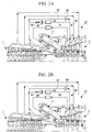
- a gas turbine GT shown in FIGS. 2A and 2B includes a compressor 1, a combustor 2, and a turbine unit 3.
- air compressed by the compressor 1 is supplied to the combustor 2, and fuel is combusted using the compressed air in the combustor 2.
- the combustion gas flows between stator blades and rotor blades of the turbine unit 3, whereby, for example, the thermal energy of the combustion gas can be extracted as shaft output.
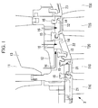
- FIG. 1 is a partial sectional view showing the inlet of the turbine of the gas turbine GT.
- Turbine rotors rotate in a casing including an outer casing 11 and a blade ring 12 by allowing the high-pressure, high-temperature combustion gas supplied from the combustor 2 to flow therein.
- the cylindrical blade ring 12 has, in sequence from the upstream side in the flow direction of the combustion gas, a plurality of stages of turbine stator blades (first-stage stator blades, second-stage stator blades, and the like) provided on the inner peripheral surface thereof. Furthermore, the turbine rotor has, similarly in sequence from the upstream side in the flow direction of the combustion gas, a plurality of stages of turbine rotor blades (first-stage rotor blades, second stage rotor blades, and the like) provided on the outer peripheral surface thereof.
- stage number of the turbine stator blades (the first-stage stator blades, the second-stage stator blades, and the like) and the stage number of the turbine rotor blades (the first-stage rotor blades, the second stage rotor blades, and the like) are not specified, they are referred to as “stator blades” or “rotor blades", without the numbers indicating the stage numbers.
- the first-stage turbine stator blades are supported by a heat shield member 15 attached to the inside of the blade ring 12.
- the second-stage turbine stator blades are supported by a heat shield member 15 attached to the inside of the blade ring 12.
- a first-stage segmented ring 31 and a second-stage segmented ring 32 are members disposed at positions opposite the tips of the first-stage turbine rotor blades and the tips of second-stage turbine rotor blades, respectively. That is, both the first-stage segmented ring 31 and the second-stage segmented ring 32 are supported by the same blade ring 12 through the heat shield member 15, and the tips of the first-stage turbine rotor blades and second-stage turbine rotor blades rotate along the inner peripheral surfaces of the first-stage segmented ring 31 and second-stage segmented ring 32.
- a gap called tip clearance is provided between the first-stage segmented ring 31 and the tips of the first-stage turbine rotor blades and between the second-stage segmented ring 32 and the tips of the second-stage turbine rotor blades, so as to prevent their mutual contact during rotation of the rotors.
- the value of the tip clearance varies because both members expand and contract due to the difference between the temperature during start-up and that during rated operation of the gas turbine GT.
- the above-described second-stage turbine stator blades are provided with an air system 40 for cooling air used for cooling.
- This cooling air system 40 is connected to the compressor 1 of the gas turbine GT, as shown in, for example, FIGS. 2A and 2B , and bleeds air from high-pressure bleed air.
- the cooling air system 40 shown in FIGS. 2A and 2B is a cooling-air flow path for supplying high-pressure bleed air bled from the high-pressure stage of the compressor 1, serving as the cooling air for the second-stage turbine stator blades T2C, to an inflow space 13 defined between the outer casing 11 and the blade ring 12.
- This cooling air system 40 includes a bypass flow path 42 through which cooling air flows during load operation, the bypass flow path 42 branching off from a main flow path 41 and extending parallel thereto.
- This bypass flow path 42 may be used as a cooling-air flow path that is selected during start-up and through which the cooling air flows.
- the flow paths 41 and 42 used during the load operation of the gas turbine GT are provided with, in sequence from the upstream side near the compressor 1, an on/off valve 43 serving as flow path switching means, a flow control orifice 44, and a cooler 45 that lowers the temperature of high-pressure bleed air, which are arranged in series. Furthermore, the bypass flow path 42 used during start-up of the gas turbine GT has a flow control orifice 46.
- stator blade 22 and the segmented ring 32 are supported by the heat shield member 15 such that a space 14 is provided between the blade ring 12 and the stator blade 22 and the segmented ring 32.
- the cooling air passed through the cooling air system 40 and introduced into the inflow space 13 passes through through-holes 16 provided in the blade ring 12 and is introduced to the blade ring 12 and the space 14 that oppose the tips of the first-stage and second-stage turbine rotor blades to cool the blade ring 12.
- the start-up operation and the load operation are performed as described below.
- the on/off valve 43 is closed to select the bypass flow path 42, as shown in FIG. 2A . Because it is necessary to raise the temperature of the low-temperature blade ring 12 during the start-up operation, the flow path with which no cooling air passes through the cooler 45 is selected. That is, high-pressure bleed air introduced from the compressor 1 is not cooled by the cooler 45 and is supplied to the inflow space 13 and the space 14 while substantially maintaining its temperature. Because this facilitates heating of the blade ring 12, the start-up time of the gas turbine GT can be reduced to achieve efficient operation.
- the on/off valve 43 is opened to select the main flow path 41 and the bypass flow path 42, as shown in FIG. 2B .
- high-pressure bleed air introduced from the compressor 1, serving as the cooling air passes through the cooler 45 and is cooled, and is supplied to the inflow space 13 and the space 14 in a low-temperature state. Because the blade ring 12 is cooled by the cooling air, the tip clearance formed relative to the tips of the first-stage turbine rotor blades and second-stage turbine rotor blades can be controlled to the optimum value.
- the cooling air system 40 through which cooling air for the second-stage turbine stator blades flows is formed on the outer periphery of the first-stage turbine rotor blades, the metal temperature of the blade ring 12 located on the outer periphery of the first-stage turbine rotor blades can be reduced.
- ACC active clearance control
- the working efficiency is improved because high-pressure bleed air is used as the cooling air, which eliminates the necessity to wait until the steam conditions are met.
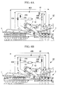
- a cooling air system 40A In a cooling air system 40A according to the first modification, part of the high-temperature compressed air introduced from the outlet of the compressor 1 as the rotor cooling air is used as the cooling air during start-up.
- a connecting tube 47 is provided for communicating between an introduction pipe 50 for high-temperature compressed air and the main flow path 41 on the downstream side of the cooler 45 is provided, and an on/off valve 48 serving as flow path switching means is provided in the connecting tube 47.
- an on/off valve 43A is provided on the upstream side of a position where the main flow path 41 and the bypass flow path 42 diverge from each other, in addition to the above-mentioned on/off valve 48 in the connecting tube 47.
- the gas turbine GT having the cooling air system 40A of the above-described configuration performs the start-up operation and the load operation as described below.
- the on/off valve 43A is closed and the on/off valve 48 is opened to select the connecting tube 47 serving as the flow path for the cooling air, as shown in FIG. 3A .
- This sends part of the outlet air of the compressor 1 to the inflow space 13 through the connecting tube 47.
- a flow path that directly introduces high-temperature compressed air is selected. That is, because high-temperature compressed air introduced from the outlet of the compressor 1 has a higher temperature than high-pressure bleed air, heating of the blade ring 12 can be further facilitated. Accordingly, the start-up time of the gas turbine GT required to heat the blade ring 12 and the like to a predetermined temperature can be further reduced to achieve efficient operation.
- the on/off valve 43A is opened and the on/off valve 48 is closed to select the main flow path 41 and the bypass flow path 42.
- high-pressure bleed air introduced from the compressor 1 as the cooling air is divided into the air passing through the main flow path 41 and the cooler 45 to be cooled and the air passing through the bypass flow path 42.
- the splitting ratio at this time is determined by the pressure loss of the cooling air caused by passing through the orifices 44 and 46 and the cooler 45, the length of the tubes, etc.
- high-pressure bleed air that has passed through the cooler 45 to be cooled and high-pressure bleed air that has flowed while maintaining its temperature are combined into a single flow by merging of the main flow path 41 and the bypass flow path 42 and are supplied to the inflow space 13 and the space 14 in a low-temperature state.
- the tip clearance formed relative to the tips of the first-stage turbine rotor blades and second-stage turbine rotor blades can be controlled to the optimum value. That is, because the cooling air system 40 through which cooling air for the second-stage turbine stator blades flows is formed on the outer periphery of the first-stage turbine rotor blades, the metal temperature of the blade ring 12 located on the outer periphery of the first-stage turbine rotor blades is reduced. Thus, it is possible to control variations of the tip clearance and to optimize the tip clearance.
- FIGS. 4A and 4B a second embodiment of the gas turbine GT of the present invention will be described on the basis of FIGS. 4A and 4B . Note that parts the same as those in the above-described embodiment will be denoted by the same reference numerals, and detailed descriptions thereof will be omitted.
- This embodiment is applied to the case where a cooling air system 40B of the second-stage turbine stator blades T2C has no cooler.
- the blade ring 12 is cooled by cooling air for the second-stage turbine stator blades T2C.
- the cooling air forms the cooling-air flow paths.
- part of the high-temperature compressed air introduced from the outlet of the compressor 1 as the rotor cooling air is used as the cooling air during start-up.
- the cooling air system 40B and the introduction pipe 50 for high-temperature compressed air are connected by a pair of connecting tubes 49A and 49B.
- One of the connecting tubes, 49A connects the cooling air system 40B at the upstream side of the orifice and the introduction pipe 50 at the downstream side of the cooler 51 and has an on/off valve 48A serving as flow path switching means at an intermediate point thereof.
- the other connecting tube, 49B connects the cooling air system 40B at the downstream side of the orifice and the introduction pipe 50 at the upstream side of the cooler 51 and has an on/off valve 48B serving as flow path switching means at an intermediate point thereof.
- the on/off valve 43A serving as flow path switching means for high-pressure bleed air used as the cooling air is provided in the cooling air system 40B.
- the tip clearance formed relative to the tips of the first-stage turbine rotor blades and second-stage turbine rotor blades can be controlled to the optimum value. That is, because the cooling air system 40B through which cooling air for the second-stage turbine stator blades flows is formed on the outer periphery of the first-stage turbine rotor blades, the metal temperature of the blade ring 12 located on the outer periphery of the first-stage turbine rotor blades can be reduced.
- the metal temperature of the blade ring 12 can be reduced.
- active clearance control ACC
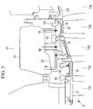
- the configuration of the above-described inlet of the turbine of the gas turbine GT is not limited to that shown in FIG. 1 , but may be the configuration of the modification shown in, for example, FIG. 5 . More specifically, compared with the configuration shown in FIG. 1 , although a difference exists in the configuration in which the outer casing 11 and the blade ring 12 are fitted together, the same inflow space 13 and the space 14 are formed in the both configurations.
Landscapes
- Engineering & Computer Science (AREA)
- Chemical & Material Sciences (AREA)
- Combustion & Propulsion (AREA)
- Mechanical Engineering (AREA)
- General Engineering & Computer Science (AREA)
- Physics & Mathematics (AREA)
- Fluid Mechanics (AREA)
- Turbine Rotor Nozzle Sealing (AREA)
- Structures Of Non-Positive Displacement Pumps (AREA)
Claims (3)
- Installation de turbine à gaz comprenant un système (40B) à air utilisé pour refroidir des aubes (T2C) statoriques de turbine de deuxième étage et un refroidisseur (51) prévu dans le système (40B) à air,
dans laquelle un premier anneau (31) segmenté de premier étage et un deuxième anneau (32) segmenté de deuxième étage, qui s'opposent à des pointes d'aubes (T1S) rotoriques de turbine de premier étage et d'aubes (T2S) rotoriques de deuxième étage, sont supportés par un même anneau (12) d'aubes et un air de refroidissement pour les aubes (T2C) statoriques de turbine de deuxième étage forme un courant d'air de refroidissement refroidissant l'anneau (12) d'aubes, pour se rendre maître de la dilatation thermique de l'anneau (12) d'aubes et pour se rendre maître d'un jeu en ce qui concerne les pointes,
dans laquelle le système (40B) à air comprendun moyen (43A, 48A, 48B) de commutation, qui commute un trajet de courant pour envoyer l'air de refroidissement,un trajet de courant principal, qui est prévu avec le refroidisseur (51) et fait passer l'air de refroidissement pendant l'opération de charge etun trajet de courant de dérivation, qui bifurque du trajet de courant principal et s'y étend parallèlement,dans laquelle le moyen (43A, 48B, 48B) de commutation est prévu avec le trajet de courant principal etdans laquelle le moyen (43A, 48B, 48B) de commutation commute le trajet de courant pour faire passer un air comprimé à température haute introduit à partir d'une sortie d'un compresseur (1) comme air de refroidissement allant au trajet de courant de dérivation pendant une opération de démarrage et commute le trajet de courant pour faire passer un air de purge de haute pression introduit à partir d'un étage de haute pression du compresseur (1) et l'air comprimé à température haute comme air de refroidissement au trajet de courant principal pendant une opération de charge. - Installation de turbine à gaz comprenant un système (40) à air utilisé pour refroidir des aubes (T2C) statoriques de turbine de deuxième étage et un refroidisseur (45) prévu dans le système (40) à air,
dans laquelle un premier anneau (31) segmenté de premier étage et un deuxième anneau (32) segmenté de deuxième étage, qui s'opposent à des pointes d'aubes (T1S) rotoriques de turbine de premier étage et d'aubes (T2S) rotoriques de deuxième étage, sont supportés par un même anneau (12) d'aubes et un air de refroidissement pour les aubes (T2C) statoriques de turbine de deuxième étage forme un courant d'air de refroidissement refroidissant l'anneau (12) d'aubes, pour se rendre maître de la dilatation thermique de l'anneau (12) d'aubes et pour se rendre maître d'un jeu en ce qui concerne les pointes,
dans laquelle le système (40) à air comprendun moyen (43) de commutation, qui commute un trajet de courant pour envoyer l'air de refroidissement,un trajet (41) de courant principal, qui est prévu avec le refroidisseur (45) et qui fait passer l'air de refroidissement pendant l'opération de charge etun trajet (42) de courant de dérivation, qui bifurque du trajet (41) de courant principal et s'y étend parallèlement,dans laquelle le moyen (43) de commutation est prévu avec le trajet (41) de courant principal etdans laquelle le moyen (43) de commutation commute le trajet de courant pour faire passer de l'air de purge de haute pression introduit à partir d'un étage de haute pression d'un compresseur (1) comme air de refroidissement au trajet (42) de dérivation pendant une opération de démarrage et commute le trajet de courant pour faire passer l'air de purge de haute pression comme air de refroidissement au trajet (41) de courant principal pendant une opération de charge. - Installation de turbine à gaz comprenant un système (40A) à air utilisé pour refroidir des aubes (T2C) statoriques de turbine de deuxième étage et un refroidisseur (45) prévu dans le système (40A) à air,
dans laquelle un premier anneau (31) segmenté de premier étage et un deuxième anneau (32) segmenté de deuxième étage, qui s'opposent à des pointes d'aubes (T1S) rotoriques de turbine de premier étage et d'aubes (T2S) rotoriques de deuxième étage, sont supportés par un même anneau (12) d'aubes et un air de refroidissement pour les aubes (T2C) statoriques de turbine de deuxième étage forme un courant d'air de refroidissement refroidissant l'anneau (12) d'aubes, pour se rendre maître de la dilatation thermique de l'anneau (12) d'aubes et pour se rendre maître d'un jeu en ce qui concerne les pointes,
dans laquelle le système à air comprendun moyen (43A, 48) de commutation, qui commute un trajet de courant pour envoyer l'air de refroidissement,un trajet (41) de courant principal, qui est prévu avec le refroidisseur (45) et qui fait passer l'air de refroidissement pendant l'opération de charge etun trajet (42) de courant de dérivation, qui bifurque du trajet (41) de courant principal et s'y étend parallèlement,dans laquelle le moyen (43A, 48) de commutation est prévu avec le trajet (41) de courant principal etdans laquelle le moyen (43A, 48) de commutation commute le trajet de courant pour faire passer un air comprimé à température haute introduit à partir d'une sortie d'un compresseur (1) comme air de refroidissement au trajet (42) de courant de dérivation pendant une opération de démarrage et commute le trajet de courant pour faire passer un air de purge sous haute pression introduit à partir d'un étage de haute pression du compresseur (1) comme air de refroidissement au trajet (41) de courant principal pendant une opération de charge.
Applications Claiming Priority (1)
| Application Number | Priority Date | Filing Date | Title |
|---|---|---|---|
| PCT/JP2009/050772 WO2010084573A1 (fr) | 2009-01-20 | 2009-01-20 | Installation de turbine à gaz |
Publications (3)
| Publication Number | Publication Date |
|---|---|
| EP2381069A1 EP2381069A1 (fr) | 2011-10-26 |
| EP2381069A4 EP2381069A4 (fr) | 2012-06-27 |
| EP2381069B1 true EP2381069B1 (fr) | 2016-03-30 |
Family
ID=42355648
Family Applications (1)
| Application Number | Title | Priority Date | Filing Date |
|---|---|---|---|
| EP09838765.7A Active EP2381069B1 (fr) | 2009-01-20 | 2009-01-20 | Installation de turbine à gaz |
Country Status (6)
| Country | Link |
|---|---|
| US (1) | US8602724B2 (fr) |
| EP (1) | EP2381069B1 (fr) |
| JP (1) | JP5174190B2 (fr) |
| KR (1) | KR101274928B1 (fr) |
| CN (1) | CN102112703B (fr) |
| WO (1) | WO2010084573A1 (fr) |
Cited By (1)
| Publication number | Priority date | Publication date | Assignee | Title |
|---|---|---|---|---|
| US10830084B2 (en) | 2017-09-13 | 2020-11-10 | MTU Aero Engines AG | Housing for a gas turbine compressor |
Families Citing this family (42)
| Publication number | Priority date | Publication date | Assignee | Title |
|---|---|---|---|---|
| EP2562369B1 (fr) * | 2011-08-22 | 2015-01-14 | Alstom Technology Ltd | Méthode pour opérer une turbine à gaz et turbine à gaz pour exécuter la méthode |
| JP2013057278A (ja) * | 2011-09-07 | 2013-03-28 | Mitsubishi Heavy Ind Ltd | ガスタービン |
| US8973373B2 (en) * | 2011-10-31 | 2015-03-10 | General Electric Company | Active clearance control system and method for gas turbine |
| US9260968B2 (en) * | 2012-04-25 | 2016-02-16 | General Electric Company | Systems and methods for reconditioning turbine engines in power generation systems |
| US9719372B2 (en) | 2012-05-01 | 2017-08-01 | General Electric Company | Gas turbomachine including a counter-flow cooling system and method |
| US9188062B2 (en) * | 2012-08-30 | 2015-11-17 | Mitsubishi Hitachi Power Systems, Ltd. | Gas turbine |
| US9562475B2 (en) | 2012-12-19 | 2017-02-07 | Siemens Aktiengesellschaft | Vane carrier temperature control system in a gas turbine engine |
| US8920109B2 (en) * | 2013-03-12 | 2014-12-30 | Siemens Aktiengesellschaft | Vane carrier thermal management arrangement and method for clearance control |
| US10087782B2 (en) * | 2013-03-13 | 2018-10-02 | United Technologies Corporation | Engine mid-turbine frame transfer tube for low pressure turbine case cooling |
| US9617921B2 (en) * | 2013-07-31 | 2017-04-11 | General Electric Company | Thermal actuator including fluid with high temperature stability |
| JP6223111B2 (ja) * | 2013-10-15 | 2017-11-01 | 三菱日立パワーシステムズ株式会社 | ガスタービン |
| JP6223774B2 (ja) * | 2013-10-15 | 2017-11-01 | 三菱日立パワーシステムズ株式会社 | ガスタービン |
| EP2896793B1 (fr) * | 2014-01-21 | 2024-08-28 | Ansaldo Energia Switzerland AG | Procédé de fonctionnement d'un ensemble de turbine à gaz et ledit ensemble |
| JP6132787B2 (ja) * | 2014-02-27 | 2017-05-24 | 三菱日立パワーシステムズ株式会社 | クリアランス調整装置、タービン装置 |
| US9963994B2 (en) * | 2014-04-08 | 2018-05-08 | General Electric Company | Method and apparatus for clearance control utilizing fuel heating |
| JP6368611B2 (ja) | 2014-10-03 | 2018-08-01 | 三菱日立パワーシステムズ株式会社 | ガスタービン、コンバインドサイクルプラント、ガスタービンの起動方法 |
| WO2016121684A1 (fr) | 2015-01-30 | 2016-08-04 | 三菱日立パワーシステムズ株式会社 | Système de refroidissement pour turbine à gaz, équipement de turbine à gaz doté de celui-ci et procédé de refroidissement d'élément pour turbine à gaz |
| JP6492737B2 (ja) * | 2015-02-19 | 2019-04-03 | 中国電力株式会社 | ガスタービン、及びガスタービンの制御方法 |
| JP5897180B2 (ja) * | 2015-04-03 | 2016-03-30 | 三菱日立パワーシステムズ株式会社 | ガスタービン |
| US10830148B2 (en) | 2015-04-24 | 2020-11-10 | Raytheon Technologies Corporation | Intercooled cooling air with dual pass heat exchanger |
| US9850819B2 (en) * | 2015-04-24 | 2017-12-26 | United Technologies Corporation | Intercooled cooling air with dual pass heat exchanger |
| US20160326915A1 (en) * | 2015-05-08 | 2016-11-10 | General Electric Company | System and method for waste heat powered active clearance control |
| KR101790146B1 (ko) | 2015-07-14 | 2017-10-25 | 두산중공업 주식회사 | 외부 케이싱으로 우회하는 냉각공기 공급유로가 마련된 냉각시스템을 포함하는 가스터빈. |
| CN106555618B (zh) * | 2015-09-30 | 2019-09-13 | 中国航发商用航空发动机有限责任公司 | 燃气轮机的叶尖间隙控制系统及其方法 |
| JP6563312B2 (ja) * | 2015-11-05 | 2019-08-21 | 川崎重工業株式会社 | ガスタービンエンジンの抽気構造 |
| CN108291452B (zh) | 2015-11-26 | 2020-10-30 | 三菱日立电力系统株式会社 | 燃气轮机及燃气轮机的部件温度调节方法 |
| US10371056B2 (en) * | 2015-12-10 | 2019-08-06 | United Technologies Corporation | Multi-source turbine cooling air |
| US10975721B2 (en) * | 2016-01-12 | 2021-04-13 | Pratt & Whitney Canada Corp. | Cooled containment case using internal plenum |
| US10794286B2 (en) | 2016-02-16 | 2020-10-06 | General Electric Company | Method and system for modulated turbine cooling as a function of engine health |
| PL232314B1 (pl) | 2016-05-06 | 2019-06-28 | Gen Electric | Maszyna przepływowa zawierająca system regulacji luzu |
| US10458429B2 (en) | 2016-05-26 | 2019-10-29 | Rolls-Royce Corporation | Impeller shroud with slidable coupling for clearance control in a centrifugal compressor |
| US10309246B2 (en) | 2016-06-07 | 2019-06-04 | General Electric Company | Passive clearance control system for gas turbomachine |
| US10392944B2 (en) | 2016-07-12 | 2019-08-27 | General Electric Company | Turbomachine component having impingement heat transfer feature, related turbomachine and storage medium |
| US10605093B2 (en) | 2016-07-12 | 2020-03-31 | General Electric Company | Heat transfer device and related turbine airfoil |
| FR3055355B1 (fr) * | 2016-08-30 | 2020-06-19 | Safran Aircraft Engines | Dispositif et procede de reglage de jeux entre un rotor et un stator concentrique d'une turbomachine |
| JP6614502B2 (ja) * | 2016-10-21 | 2019-12-04 | 三菱重工業株式会社 | 蒸気タービン |
| US11795877B2 (en) * | 2020-03-24 | 2023-10-24 | Siemens Energy, Inc. | Method for modulating a turbine cooling supply for gas turbine applications |
| KR102768138B1 (ko) * | 2020-09-08 | 2025-02-13 | 미츠비시 파워 가부시키가이샤 | 가스 터빈의 클리어런스 제어 시스템 |
| CN119604668A (zh) * | 2022-08-09 | 2025-03-11 | 西门子能源国际公司 | 带有涡轮轮叶承载件冷却流路的燃气涡轮发动机 |
| US12345163B2 (en) | 2023-11-17 | 2025-07-01 | Rolls-Royce Corporation | Travel stop for a tip clearance control system |
| US12345162B2 (en) | 2023-11-17 | 2025-07-01 | Rolls-Royce Corporation | Adjustable position impeller shroud for centrifugal compressors |
| FR3156160A1 (fr) * | 2023-12-04 | 2025-06-06 | Safran Aircraft Engines | Dispositif et procédé de régulation des jeux radiaux au niveau de la turbine basse pression |
Family Cites Families (15)
| Publication number | Priority date | Publication date | Assignee | Title |
|---|---|---|---|---|
| US3966354A (en) | 1974-12-19 | 1976-06-29 | General Electric Company | Thermal actuated valve for clearance control |
| JPS62182444A (ja) * | 1986-02-07 | 1987-08-10 | Hitachi Ltd | ガスタ−ビン冷却空気制御方法及び装置 |
| FR2614073B1 (fr) | 1987-04-15 | 1992-02-14 | Snecma | Dispositif d'ajustement en temps reel du jeu radial entre un rotor et un stator de turbomachine |
| JPS6477804A (en) | 1988-06-07 | 1989-03-23 | Fujikura Ltd | Tape electric wire |
| JPH05186615A (ja) | 1992-01-16 | 1993-07-27 | Nisshinbo Ind Inc | シート材料及びその製造方法 |
| US5305616A (en) | 1992-03-23 | 1994-04-26 | General Electric Company | Gas turbine engine cooling system |
| FR2708669B1 (fr) * | 1993-08-05 | 1995-09-08 | Snecma | Système de ventilation des disques et du stator de turbine d'un turboréacteur. |
| JPH0754669A (ja) | 1993-08-09 | 1995-02-28 | Mitsubishi Heavy Ind Ltd | ガスタービン冷却空気制御装置 |
| US5779436A (en) * | 1996-08-07 | 1998-07-14 | Solar Turbines Incorporated | Turbine blade clearance control system |
| JP3825279B2 (ja) | 2001-06-04 | 2006-09-27 | 三菱重工業株式会社 | ガスタービン |
| US6968696B2 (en) * | 2003-09-04 | 2005-11-29 | Siemens Westinghouse Power Corporation | Part load blade tip clearance control |
| US7096673B2 (en) * | 2003-10-08 | 2006-08-29 | Siemens Westinghouse Power Corporation | Blade tip clearance control |
| US7269955B2 (en) | 2004-08-25 | 2007-09-18 | General Electric Company | Methods and apparatus for maintaining rotor assembly tip clearances |
| US7823389B2 (en) | 2006-11-15 | 2010-11-02 | General Electric Company | Compound clearance control engine |
| WO2011142439A1 (fr) | 2010-05-13 | 2011-11-17 | オリエンタル酵母工業株式会社 | Procédé d'amélioration de la qualité du pain, etc. |
-
2009
- 2009-01-20 KR KR1020117001997A patent/KR101274928B1/ko not_active Expired - Fee Related
- 2009-01-20 WO PCT/JP2009/050772 patent/WO2010084573A1/fr not_active Ceased
- 2009-01-20 EP EP09838765.7A patent/EP2381069B1/fr active Active
- 2009-01-20 JP JP2010547334A patent/JP5174190B2/ja active Active
- 2009-01-20 US US13/056,054 patent/US8602724B2/en active Active
- 2009-01-20 CN CN200980129565.7A patent/CN102112703B/zh active Active
Cited By (1)
| Publication number | Priority date | Publication date | Assignee | Title |
|---|---|---|---|---|
| US10830084B2 (en) | 2017-09-13 | 2020-11-10 | MTU Aero Engines AG | Housing for a gas turbine compressor |
Also Published As
| Publication number | Publication date |
|---|---|
| WO2010084573A1 (fr) | 2010-07-29 |
| EP2381069A4 (fr) | 2012-06-27 |
| KR101274928B1 (ko) | 2013-06-17 |
| CN102112703A (zh) | 2011-06-29 |
| KR20110020946A (ko) | 2011-03-03 |
| US20110135456A1 (en) | 2011-06-09 |
| EP2381069A1 (fr) | 2011-10-26 |
| US8602724B2 (en) | 2013-12-10 |
| CN102112703B (zh) | 2014-07-23 |
| JPWO2010084573A1 (ja) | 2012-07-12 |
| JP5174190B2 (ja) | 2013-04-03 |
Similar Documents
| Publication | Publication Date | Title |
|---|---|---|
| EP2381069B1 (fr) | Installation de turbine à gaz | |
| US8181443B2 (en) | Heat exchanger to cool turbine air cooling flow | |
| US9562475B2 (en) | Vane carrier temperature control system in a gas turbine engine | |
| CA2522168C (fr) | Systeme hybride de regulation de l'espace a l'extremite de pales de turbine | |
| EP2531709B1 (fr) | Refroidissement de composants de turbine utilisant l'air d'enveloppe de la chambre de combustion | |
| US8973373B2 (en) | Active clearance control system and method for gas turbine | |
| JP6589211B2 (ja) | ガスタービン、及びその部品温度調節方法 | |
| US7269955B2 (en) | Methods and apparatus for maintaining rotor assembly tip clearances | |
| EP3022503B1 (fr) | Entretoise pour compresseur de turbine à gaz. | |
| JPH10103004A (ja) | ガスタービンの動翼冷却装置 | |
| US11976562B2 (en) | System for controlling blade clearances within a gas turbine engine | |
| CN109563744B (zh) | 带有吸气面密封的涡轮发动机 | |
| EP3379036B1 (fr) | Moteur à turbine à gaz | |
| JPS63159626A (ja) | ガスタ−ビンケ−シングの温度制御方法および温度制御装置 | |
| WO2020046375A1 (fr) | Procédé de fonctionnement d'un système de chauffage d'entrée pour une commande de jeu |
Legal Events
| Date | Code | Title | Description |
|---|---|---|---|
| PUAI | Public reference made under article 153(3) epc to a published international application that has entered the european phase |
Free format text: ORIGINAL CODE: 0009012 |
|
| 17P | Request for examination filed |
Effective date: 20101222 |
|
| AK | Designated contracting states |
Kind code of ref document: A1 Designated state(s): AT BE BG CH CY CZ DE DK EE ES FI FR GB GR HR HU IE IS IT LI LT LU LV MC MK MT NL NO PL PT RO SE SI SK TR |
|
| DAX | Request for extension of the european patent (deleted) | ||
| A4 | Supplementary search report drawn up and despatched |
Effective date: 20120531 |
|
| RIC1 | Information provided on ipc code assigned before grant |
Ipc: F01D 11/08 20060101AFI20120524BHEP Ipc: F02C 9/18 20060101ALI20120524BHEP Ipc: F02C 7/18 20060101ALI20120524BHEP Ipc: F01D 11/24 20060101ALI20120524BHEP Ipc: F02C 7/28 20060101ALI20120524BHEP Ipc: F02C 7/143 20060101ALI20120524BHEP |
|
| 17Q | First examination report despatched |
Effective date: 20150323 |
|
| REG | Reference to a national code |
Ref country code: DE Ref legal event code: R079 Ref document number: 602009037428 Country of ref document: DE Free format text: PREVIOUS MAIN CLASS: F01D0011080000 Ipc: F01D0009040000 |
|
| GRAP | Despatch of communication of intention to grant a patent |
Free format text: ORIGINAL CODE: EPIDOSNIGR1 |
|
| RIC1 | Information provided on ipc code assigned before grant |
Ipc: F01D 9/04 20060101AFI20150817BHEP Ipc: F02C 7/28 20060101ALI20150817BHEP Ipc: F01D 11/24 20060101ALI20150817BHEP Ipc: F01D 11/08 20060101ALI20150817BHEP Ipc: F02C 7/18 20060101ALI20150817BHEP Ipc: F02C 7/143 20060101ALI20150817BHEP Ipc: F02C 9/18 20060101ALI20150817BHEP |
|
| INTG | Intention to grant announced |
Effective date: 20150921 |
|
| GRAS | Grant fee paid |
Free format text: ORIGINAL CODE: EPIDOSNIGR3 |
|
| GRAA | (expected) grant |
Free format text: ORIGINAL CODE: 0009210 |
|
| AK | Designated contracting states |
Kind code of ref document: B1 Designated state(s): AT BE BG CH CY CZ DE DK EE ES FI FR GB GR HR HU IE IS IT LI LT LU LV MC MK MT NL NO PL PT RO SE SI SK TR |
|
| REG | Reference to a national code |
Ref country code: GB Ref legal event code: FG4D |
|
| REG | Reference to a national code |
Ref country code: CH Ref legal event code: EP |
|
| REG | Reference to a national code |
Ref country code: AT Ref legal event code: REF Ref document number: 785638 Country of ref document: AT Kind code of ref document: T Effective date: 20160415 |
|
| REG | Reference to a national code |
Ref country code: IE Ref legal event code: FG4D |
|
| REG | Reference to a national code |
Ref country code: DE Ref legal event code: R096 Ref document number: 602009037428 Country of ref document: DE |
|
| REG | Reference to a national code |
Ref country code: LT Ref legal event code: MG4D |
|
| PG25 | Lapsed in a contracting state [announced via postgrant information from national office to epo] |
Ref country code: HR Free format text: LAPSE BECAUSE OF FAILURE TO SUBMIT A TRANSLATION OF THE DESCRIPTION OR TO PAY THE FEE WITHIN THE PRESCRIBED TIME-LIMIT Effective date: 20160330 Ref country code: FI Free format text: LAPSE BECAUSE OF FAILURE TO SUBMIT A TRANSLATION OF THE DESCRIPTION OR TO PAY THE FEE WITHIN THE PRESCRIBED TIME-LIMIT Effective date: 20160330 Ref country code: GR Free format text: LAPSE BECAUSE OF FAILURE TO SUBMIT A TRANSLATION OF THE DESCRIPTION OR TO PAY THE FEE WITHIN THE PRESCRIBED TIME-LIMIT Effective date: 20160701 Ref country code: NO Free format text: LAPSE BECAUSE OF FAILURE TO SUBMIT A TRANSLATION OF THE DESCRIPTION OR TO PAY THE FEE WITHIN THE PRESCRIBED TIME-LIMIT Effective date: 20160630 |
|
| REG | Reference to a national code |
Ref country code: NL Ref legal event code: MP Effective date: 20160330 |
|
| REG | Reference to a national code |
Ref country code: AT Ref legal event code: MK05 Ref document number: 785638 Country of ref document: AT Kind code of ref document: T Effective date: 20160330 |
|
| PG25 | Lapsed in a contracting state [announced via postgrant information from national office to epo] |
Ref country code: LV Free format text: LAPSE BECAUSE OF FAILURE TO SUBMIT A TRANSLATION OF THE DESCRIPTION OR TO PAY THE FEE WITHIN THE PRESCRIBED TIME-LIMIT Effective date: 20160330 Ref country code: LT Free format text: LAPSE BECAUSE OF FAILURE TO SUBMIT A TRANSLATION OF THE DESCRIPTION OR TO PAY THE FEE WITHIN THE PRESCRIBED TIME-LIMIT Effective date: 20160330 Ref country code: SE Free format text: LAPSE BECAUSE OF FAILURE TO SUBMIT A TRANSLATION OF THE DESCRIPTION OR TO PAY THE FEE WITHIN THE PRESCRIBED TIME-LIMIT Effective date: 20160330 |
|
| PG25 | Lapsed in a contracting state [announced via postgrant information from national office to epo] |
Ref country code: NL Free format text: LAPSE BECAUSE OF FAILURE TO SUBMIT A TRANSLATION OF THE DESCRIPTION OR TO PAY THE FEE WITHIN THE PRESCRIBED TIME-LIMIT Effective date: 20160330 |
|
| PG25 | Lapsed in a contracting state [announced via postgrant information from national office to epo] |
Ref country code: PL Free format text: LAPSE BECAUSE OF FAILURE TO SUBMIT A TRANSLATION OF THE DESCRIPTION OR TO PAY THE FEE WITHIN THE PRESCRIBED TIME-LIMIT Effective date: 20160330 Ref country code: IS Free format text: LAPSE BECAUSE OF FAILURE TO SUBMIT A TRANSLATION OF THE DESCRIPTION OR TO PAY THE FEE WITHIN THE PRESCRIBED TIME-LIMIT Effective date: 20160730 Ref country code: EE Free format text: LAPSE BECAUSE OF FAILURE TO SUBMIT A TRANSLATION OF THE DESCRIPTION OR TO PAY THE FEE WITHIN THE PRESCRIBED TIME-LIMIT Effective date: 20160330 |
|
| PG25 | Lapsed in a contracting state [announced via postgrant information from national office to epo] |
Ref country code: AT Free format text: LAPSE BECAUSE OF FAILURE TO SUBMIT A TRANSLATION OF THE DESCRIPTION OR TO PAY THE FEE WITHIN THE PRESCRIBED TIME-LIMIT Effective date: 20160330 Ref country code: PT Free format text: LAPSE BECAUSE OF FAILURE TO SUBMIT A TRANSLATION OF THE DESCRIPTION OR TO PAY THE FEE WITHIN THE PRESCRIBED TIME-LIMIT Effective date: 20160801 Ref country code: RO Free format text: LAPSE BECAUSE OF FAILURE TO SUBMIT A TRANSLATION OF THE DESCRIPTION OR TO PAY THE FEE WITHIN THE PRESCRIBED TIME-LIMIT Effective date: 20160330 Ref country code: ES Free format text: LAPSE BECAUSE OF FAILURE TO SUBMIT A TRANSLATION OF THE DESCRIPTION OR TO PAY THE FEE WITHIN THE PRESCRIBED TIME-LIMIT Effective date: 20160330 Ref country code: SK Free format text: LAPSE BECAUSE OF FAILURE TO SUBMIT A TRANSLATION OF THE DESCRIPTION OR TO PAY THE FEE WITHIN THE PRESCRIBED TIME-LIMIT Effective date: 20160330 Ref country code: CZ Free format text: LAPSE BECAUSE OF FAILURE TO SUBMIT A TRANSLATION OF THE DESCRIPTION OR TO PAY THE FEE WITHIN THE PRESCRIBED TIME-LIMIT Effective date: 20160330 |
|
| PG25 | Lapsed in a contracting state [announced via postgrant information from national office to epo] |
Ref country code: IT Free format text: LAPSE BECAUSE OF FAILURE TO SUBMIT A TRANSLATION OF THE DESCRIPTION OR TO PAY THE FEE WITHIN THE PRESCRIBED TIME-LIMIT Effective date: 20160330 Ref country code: BE Free format text: LAPSE BECAUSE OF FAILURE TO SUBMIT A TRANSLATION OF THE DESCRIPTION OR TO PAY THE FEE WITHIN THE PRESCRIBED TIME-LIMIT Effective date: 20160330 |
|
| REG | Reference to a national code |
Ref country code: DE Ref legal event code: R097 Ref document number: 602009037428 Country of ref document: DE |
|
| PG25 | Lapsed in a contracting state [announced via postgrant information from national office to epo] |
Ref country code: DK Free format text: LAPSE BECAUSE OF FAILURE TO SUBMIT A TRANSLATION OF THE DESCRIPTION OR TO PAY THE FEE WITHIN THE PRESCRIBED TIME-LIMIT Effective date: 20160330 |
|
| PLBE | No opposition filed within time limit |
Free format text: ORIGINAL CODE: 0009261 |
|
| STAA | Information on the status of an ep patent application or granted ep patent |
Free format text: STATUS: NO OPPOSITION FILED WITHIN TIME LIMIT |
|
| 26N | No opposition filed |
Effective date: 20170103 |
|
| PG25 | Lapsed in a contracting state [announced via postgrant information from national office to epo] |
Ref country code: SI Free format text: LAPSE BECAUSE OF FAILURE TO SUBMIT A TRANSLATION OF THE DESCRIPTION OR TO PAY THE FEE WITHIN THE PRESCRIBED TIME-LIMIT Effective date: 20160330 |
|
| REG | Reference to a national code |
Ref country code: CH Ref legal event code: PL |
|
| GBPC | Gb: european patent ceased through non-payment of renewal fee |
Effective date: 20170120 |
|
| PG25 | Lapsed in a contracting state [announced via postgrant information from national office to epo] |
Ref country code: MC Free format text: LAPSE BECAUSE OF FAILURE TO SUBMIT A TRANSLATION OF THE DESCRIPTION OR TO PAY THE FEE WITHIN THE PRESCRIBED TIME-LIMIT Effective date: 20160330 |
|
| REG | Reference to a national code |
Ref country code: FR Ref legal event code: ST Effective date: 20170929 |
|
| PG25 | Lapsed in a contracting state [announced via postgrant information from national office to epo] |
Ref country code: CH Free format text: LAPSE BECAUSE OF NON-PAYMENT OF DUE FEES Effective date: 20170131 Ref country code: FR Free format text: LAPSE BECAUSE OF NON-PAYMENT OF DUE FEES Effective date: 20170131 Ref country code: LI Free format text: LAPSE BECAUSE OF NON-PAYMENT OF DUE FEES Effective date: 20170131 |
|
| REG | Reference to a national code |
Ref country code: IE Ref legal event code: MM4A |
|
| PG25 | Lapsed in a contracting state [announced via postgrant information from national office to epo] |
Ref country code: LU Free format text: LAPSE BECAUSE OF NON-PAYMENT OF DUE FEES Effective date: 20170120 Ref country code: GB Free format text: LAPSE BECAUSE OF NON-PAYMENT OF DUE FEES Effective date: 20170120 |
|
| PG25 | Lapsed in a contracting state [announced via postgrant information from national office to epo] |
Ref country code: IE Free format text: LAPSE BECAUSE OF NON-PAYMENT OF DUE FEES Effective date: 20170120 |
|
| PG25 | Lapsed in a contracting state [announced via postgrant information from national office to epo] |
Ref country code: MT Free format text: LAPSE BECAUSE OF NON-PAYMENT OF DUE FEES Effective date: 20170120 |
|
| PG25 | Lapsed in a contracting state [announced via postgrant information from national office to epo] |
Ref country code: HU Free format text: LAPSE BECAUSE OF FAILURE TO SUBMIT A TRANSLATION OF THE DESCRIPTION OR TO PAY THE FEE WITHIN THE PRESCRIBED TIME-LIMIT; INVALID AB INITIO Effective date: 20090120 |
|
| PG25 | Lapsed in a contracting state [announced via postgrant information from national office to epo] |
Ref country code: BG Free format text: LAPSE BECAUSE OF FAILURE TO SUBMIT A TRANSLATION OF THE DESCRIPTION OR TO PAY THE FEE WITHIN THE PRESCRIBED TIME-LIMIT Effective date: 20160330 |
|
| PG25 | Lapsed in a contracting state [announced via postgrant information from national office to epo] |
Ref country code: CY Free format text: LAPSE BECAUSE OF NON-PAYMENT OF DUE FEES Effective date: 20160330 |
|
| PG25 | Lapsed in a contracting state [announced via postgrant information from national office to epo] |
Ref country code: MK Free format text: LAPSE BECAUSE OF FAILURE TO SUBMIT A TRANSLATION OF THE DESCRIPTION OR TO PAY THE FEE WITHIN THE PRESCRIBED TIME-LIMIT Effective date: 20160330 |
|
| PG25 | Lapsed in a contracting state [announced via postgrant information from national office to epo] |
Ref country code: TR Free format text: LAPSE BECAUSE OF FAILURE TO SUBMIT A TRANSLATION OF THE DESCRIPTION OR TO PAY THE FEE WITHIN THE PRESCRIBED TIME-LIMIT Effective date: 20160330 |
|
| PGFP | Annual fee paid to national office [announced via postgrant information from national office to epo] |
Ref country code: DE Payment date: 20241203 Year of fee payment: 17 |