EP2380773A2 - Anchorage for automobile optical groups - Google Patents
Anchorage for automobile optical groups Download PDFInfo
- Publication number
- EP2380773A2 EP2380773A2 EP11380037A EP11380037A EP2380773A2 EP 2380773 A2 EP2380773 A2 EP 2380773A2 EP 11380037 A EP11380037 A EP 11380037A EP 11380037 A EP11380037 A EP 11380037A EP 2380773 A2 EP2380773 A2 EP 2380773A2
- Authority
- EP
- European Patent Office
- Prior art keywords
- optical group
- vehicle
- carcass
- skid
- fixing
- Prior art date
- Legal status (The legal status is an assumption and is not a legal conclusion. Google has not performed a legal analysis and makes no representation as to the accuracy of the status listed.)
- Granted
Links
Images


Classifications
-
- B—PERFORMING OPERATIONS; TRANSPORTING
- B60—VEHICLES IN GENERAL
- B60Q—ARRANGEMENT OF SIGNALLING OR LIGHTING DEVICES, THE MOUNTING OR SUPPORTING THEREOF OR CIRCUITS THEREFOR, FOR VEHICLES IN GENERAL
- B60Q1/00—Arrangement of optical signalling or lighting devices, the mounting or supporting thereof or circuits therefor
- B60Q1/02—Arrangement of optical signalling or lighting devices, the mounting or supporting thereof or circuits therefor the devices being primarily intended to illuminate the way ahead or to illuminate other areas of way or environments
- B60Q1/04—Arrangement of optical signalling or lighting devices, the mounting or supporting thereof or circuits therefor the devices being primarily intended to illuminate the way ahead or to illuminate other areas of way or environments the devices being headlights
- B60Q1/0408—Arrangement of optical signalling or lighting devices, the mounting or supporting thereof or circuits therefor the devices being primarily intended to illuminate the way ahead or to illuminate other areas of way or environments the devices being headlights built into the vehicle body, e.g. details concerning the mounting of the headlamps on the vehicle body
- B60Q1/0433—Arrangement of optical signalling or lighting devices, the mounting or supporting thereof or circuits therefor the devices being primarily intended to illuminate the way ahead or to illuminate other areas of way or environments the devices being headlights built into the vehicle body, e.g. details concerning the mounting of the headlamps on the vehicle body the housing being fastened onto the vehicle body using screws
-
- B—PERFORMING OPERATIONS; TRANSPORTING
- B60—VEHICLES IN GENERAL
- B60Q—ARRANGEMENT OF SIGNALLING OR LIGHTING DEVICES, THE MOUNTING OR SUPPORTING THEREOF OR CIRCUITS THEREFOR, FOR VEHICLES IN GENERAL
- B60Q1/00—Arrangement of optical signalling or lighting devices, the mounting or supporting thereof or circuits therefor
- B60Q1/02—Arrangement of optical signalling or lighting devices, the mounting or supporting thereof or circuits therefor the devices being primarily intended to illuminate the way ahead or to illuminate other areas of way or environments
- B60Q1/04—Arrangement of optical signalling or lighting devices, the mounting or supporting thereof or circuits therefor the devices being primarily intended to illuminate the way ahead or to illuminate other areas of way or environments the devices being headlights
- B60Q1/0408—Arrangement of optical signalling or lighting devices, the mounting or supporting thereof or circuits therefor the devices being primarily intended to illuminate the way ahead or to illuminate other areas of way or environments the devices being headlights built into the vehicle body, e.g. details concerning the mounting of the headlamps on the vehicle body
- B60Q1/045—Arrangement of optical signalling or lighting devices, the mounting or supporting thereof or circuits therefor the devices being primarily intended to illuminate the way ahead or to illuminate other areas of way or environments the devices being headlights built into the vehicle body, e.g. details concerning the mounting of the headlamps on the vehicle body with provision for adjusting the alignment of the headlamp housing with respect to the vehicle body
Abstract
Description
- The present invention refers to an anchorage for automobile optical groups, such as headlights and pilot lights, which enables the regulation of its position in the three space directions.
- More specifically, the anchorage of the invention is of the type comprising a set of fixing points which immobilize the carcass of the optical group to the vehicle structure in the X, Y and Z directions, belonging to a system of axes the origin of which is in the optical group and whose X axis coincides with the direction of the beam of light of said optical group.
- Automobile headlights are mounted in the frontal structure thereof through several fixings, which prevent the movement of the headlight, and all that so as to secure their position, once mounted.
- In order to be able to adjust its correct position, the fixings of headlights nowadays have different adjustment systems, which enable the correct placement of the headlight, but with the inconvenience that the fine adjustment of the headlight may require the dismounting of the surrounding parts which have been mounted before.
- In current automobile design, many of them have bumpers covering the lower anchorages of the headlights making them inaccessible for their adjustment after mounting.
- From
IT TO980082 - From
FR 9707790 FR 9208989 - From
DE 19835047 it is known a device for the adjustable fixing of a headlight which has two upper supports and two lower supports which allow the movement of the headlight only in the transverse horizontal direction of the vehicle fixing the position in the longitudinal and transverse vertical directions of the vehicle. This system is based on supports, moving in the transverse horizontal direction with respect to the carcass of the headlight housed in the lower supports of the headlight and fixed to the chassis, which have two guiding grooves and a complex element which rotates to distinguish between the mounting position and the displacement position. This system has the disadvantage that the upper supports only have clearance to allow movement, but do not collaborate with the adjustment, while the lower supports are very complex parts and only allow the adjustment in one direction. Given their double function of support and adjustment guide, the supports are very complex and need two opposite positions in 90°, one for their mounting and another for the adjustment. - The object of the present invention is an anchorage for optical groups which enables to facilitate and secure the adjustment and mounting of the optical group, headlight, or pilot lights, to the chassis of the vehicle without any need to dismount surrounding parts which have to be mounted again later if the first mounting of the headlight is not satisfactory. All of this thanks to an innovative anchorage which initially fixes the degree of freedom in Z (transverse vertical displacement with respect to the beam of light direction) of the headlight and it always leaves two degrees of freedom X (longitudinal displacement with respect to the beam of light direction) and Y (transverse horizontal displacement with respect to the beam of light direction).
- To that end, according to the invention, the anchorage comprises a first fixing point, which has means to immobilize the carcass of the optical group to the structure of the vehicle only in the Z direction, and at least a second fixing point, and preferably two, which have means to immobilize the carcass of the optical group to the structure of the vehicle in the X and Y directions.
- According to an embodiment, the first fixing point will be located at a lower height than the second fixing point(s).
- The immobilization means of the first lower fixing point are constituted by a skid which is connected on one side to the optical group, through guides belonging to the optical group and parallel to the beam of light of said optical group, while on the other side it is fixed to the structure of the vehicle through a set of screw and jam nut. The skid is mounted on the guides of the optical group with transverse clearance and longitudinal freedom of displacement, conditions which allow the freedom of movement in the X and Y directions which will be fixed to the upper anchorage points.
- With the anchorage of the invention, the position of the optical group can be fixed on the structure bearing it in the Z direction (vertical), while its position in the other two directions X and Y can be adjusted, after mounting the bumper or another part covering the fixing and making it inaccessible later.
- Also, the other fixings, of the second fixing points, which are accessible through the upper part, allow the adjustment in the other two directions X and Y and their later fixing, and they can even allow a slight adjustment in the Z direction by pivoting on the first fixing.point.
- The simplicity of,the lower support enables one fixing to assume the function of vertical direction positioning, for example, a screw, while the function that enables the adjustment of the other two horizontal directions can be assumed by a guiding system and a skid with 2 degrees of freedom in X and Y.
- Thanks to the fact that the first fixing point allows elevated fixing and still allows the adjustment in the other two directions, additional parts covering it can be mounted definitively, such as for example, a vehicle front bumper, covering it.
- This, added to the upper fixings, accessible from the upper part of the set, allows for more varied designs of the other surrounding parts.
- Also, it is shown, through the vibration tests, that the headlights or pilot lights which have at least one lower fixing withstand those vibrations better than those without lower fixing and therefore this invention benefits from the fixing appropriately maintaining the weight and withstanding the vibrations of the headlight or pilot light, reducing the risk of breaking of any part due to the contact between adjoining elements.
- The skid can be constituted by a base platform the longitudinal edges of which are housed in other opposite channels of the optical group, channels which define the skid guides. From the platform there protrudes an upper transverse partition, which has an oblong opening through which there passes a set of screw and fixing nut of the optical group in the Z direction.
- The attached drawings show, as an example, an embodiment of the anchorage of the invention for fixing automobile optical groups. In the drawings:
-
Figure 1 shows a front perspective view of a headlight mounted on the structure or chassis of an automobile; with the anchorage of the invention. -
Figure 2 shows a rear perspective view of the optical group included infigure 1 , with the anchorage of the invention. -
Figure 3 corresponds to detail A offigure 2 , at a greater scale. -
Figure 4 is a longitudinal sectional view of the lower fixing point of the anchorage of the invention, taken according to the cutting line IV-IV offigure 3 . -
Figure 5 is an elevated view of the skid which forms part of the lower fixing point, mounted on the structure or chassis of the automobile. -
Figure 6 is a vertical sectional view of the skid mounted on the structure or chassis of the automobile, taken according to the cutting line VI-VI offigure 5 . -
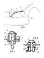
Figure 7 is a similar view tofigure 1 , with the front bumper mounted on the structure or chassis of the automobile, partially covering the lower part of the optical group. -
Figure 8 is a diametrical sectional view of a possible embodiment of one of the upper fixing points. -
Figure 9 is a diametrical sectional view of an embodiment variant of one of the upper fixing points. - The characteristics and advantages of the invention can be understood better with the following description, of an embodiment example shown in the aforementioned drawings.
-
Figure 1 shows a partial perspective front view of an automobile including an optical group constituted by a headlight thecarcass 1 of which is fixed to the structure or chassis of the automobile through alower fixing point 2 and three second fixing points which are indicated withreference number 3, the first fixing point being located at a lower height than the second fixing points. The firstlower fixing point 2 has means to immobilize thecarcass 1 of the headlight to the automobile structure in the Z direction. Through the secondupper fixing points 3 thecarcass 1 of the headlight is fixed to the automobile structure in directions Z and Y. - The first lower fixing point is constituted, as it can be seen in
figures 2 to 4 , by a skid which is indicated in general withreference 4 and which connects on one side with thecarcass 1 of the headlight throughguides 5 belonging to said headlight, and on the other side to the chassis orstructure 5 of the automobile,figure 1 , as it can be seen infigures 5 and 6 . - In the example described and as it can be better seen in
figures 3 and 4 , theskid 4 is constituted by abase platform 6 from which there protrude from the lower part two lowerlongitudinal feet 7, which are housed in theguides 5, belonging to the carcass of theheadlight 1, consisting of opposite parallel channels in which thelongitudinal feet 7 are housed with certain clearance D,figure 4 . From theplatform 6 there protrudes, on the side opposite the one of thefeet 7, atransverse partition 8, perpendicular to the lowerlongitudinal feet 7, transverse partition which has anoblong opening 9 through which there passes a set ofscrew 10 andnut 11 for its fixing to the structure orchassis 5 of the automobile, as shown infigures 5 and 6 . - With the constitution described, the
skid 4, once mounted on theguides 5,figure 4 , is prevented from moving with respect to thecarcass 1 of the headlight in the Z direction, while it can move in the Y direction, thanks to the clearances D, and also along theguides 5, parallel to the direction of the beam of light and therefore to the X direction. - Through the second
upper fixing points 3 it is attained the immobilization of thecarcass 1 of the headlight in the structure orchassis 5 of the automobile in the X and Y directions.Figure 6 shows how thepartition 8 forms part of theskid 4 which is fixed to the structure orchassis 5 of the automobile, once the desired position of the headlight has been selected according to the Z direction, corresponding to the transverse vertical direction with respect to the direction of the beam of light of the headlight. Once this position has been selected, additional parts can be mounted covering the firstlower fixing point 2, such as theautomobile bumper 12,figure 7 . Next, the transverse horizontal positions, in the Y axis, and the longitudinal position, in the X axis, can be fixed through the secondupper fixing points 3, which can be constituted by a set ofnut 13 andscrew 14, as shown infigure 8 . In this fixing, thenut 13 rests on the structure orchassis 5 of the automobile. When the nut is rotated, thecarcass 1 of the headlight is elevated or lowered. Once the exact height situation is chosen, the position is fixed permanently by thescrew 14 andjam nut 15. -
Figure 9 shows another possible embodiment of the secondupper fixing points 3, through anut 16 which can be regulated elevated over thecarcass 1 of the headlight, being located under or over the structure orchassis 5 of the automobile. Thenut 16 is inaccessible to regulate the distance between the structure orchassis 5 of the automobile and thecarcass 1 of the headlight. The access is attained through an opening which allows the insertion of anut 17 which is grooved in a manner complementary to the lower part of the opening of thenut 16. By rotating the accessible part of thenut 17, thenut 16 is rotated, which is the one that regulates the height between the headlight and the structure or chassis of the automobile. Finally, the position is fixed with ajam screw 18. - The embodiments shown in
figures 8 and 9 only constitute possible embodiment examples of the secondupper fixing points 3. - To summarize, for the mounting of the
carcass 1 of the headlight the position thereof is fixed in the Z direction through the set ofnut 11 andscrew 10 which passes through theoblong opening 9 of theskid 4. Next, the fixing in the X and Y directions is attained through the secondupper fixing points 3 which, in the example shown in the drawings are constituted by three sets which can correspond to the embodiments shown infigures 8 and 9 . - In order to regulate again the position of the headlight in the horizontal and longitudinal transverse directions, that is, in the directions of the X and Y axes, the first step is to release the fixing defined by the second
upper fixing points 3 and move the headlight which will displace freely in said directions thanks to the constitution of theskid 4 and to the clearance between theplatform 6 and theguides 5, described with reference tofigure 4 . Once the desired position is attained, the headlight is fixed again through the tightening of the second fixing points 3, without needing to dismount thebumper 12 or any other additional part covering thelower fixing point 2.
Claims (3)
- Anchorage for automobile optical groups, through a set of fixing points which immobilizes the carcass of the optical group to the structure of the vehicle in the X, Y and Z directions, belonging to a system of axes the origin of which is in the optical group and whose X axis coincides with the direction of the beam of light of said optical group, characterized in that it comprises a first fixing point, which has means to immobilize the carcass of the optical group to the structure of the vehicle only in the Z direction, and at least a second fixing point which has means to immobilize the carcass of the optical group to the structure of the vehicle in the X and Y directions; the immobilization means of the first fixing point being constituted by a skid which is connected on one side to the optical group, through guides belonging to the optical group, parallel to the beam of light of said optical group, while the other side is fixed to the structure of the vehicle through a set of jam screw and nut, said skid which is mounted on guides of the optical group with transverse clearance and freedom of longitudinal displacement; and in that the second fixing point is constituted by sets of screws and nut which secure the optical group to the structure of the vehicle in the X and Y directions.
- Anchorage according to claim 1, characterized in that the skid comprises a base platform, while the optical group has two opposite channels, parallel to the direction of the beam of light of said optical group, which define the guides in which the longitudinal edges of the skid platform are housed, with transverse clearance between said edges and channels, with a transverse partition also protruding from the platform, on the side opposite the one facing the optical group, said partition which has an oblong opening through which there passes the set of screw and nut for fixing the optical group to the structure of chassis of the vehicle in the Z direction.
- Anchorage according to claim 2, characterized in that the base platform has in the lower part and adjacent to its longitudinal edges, longitudinal feet which are housed, together with said edges, in the opposite channels of the optical group.
Applications Claiming Priority (1)
| Application Number | Priority Date | Filing Date | Title |
|---|---|---|---|
| ES201030372U ES1072430Y (en) | 2010-04-26 | 2010-04-26 | ANCHORAGE FOR OPTICAL CAR GROUPS |
Publications (3)
| Publication Number | Publication Date |
|---|---|
| EP2380773A2 true EP2380773A2 (en) | 2011-10-26 |
| EP2380773A3 EP2380773A3 (en) | 2014-07-30 |
| EP2380773B1 EP2380773B1 (en) | 2019-07-10 |
Family
ID=42286648
Family Applications (1)
| Application Number | Title | Priority Date | Filing Date |
|---|---|---|---|
| EP11380037.9A Active EP2380773B1 (en) | 2010-04-26 | 2011-04-20 | Automobile optical group and method of mounting thereof |
Country Status (2)
| Country | Link |
|---|---|
| EP (1) | EP2380773B1 (en) |
| ES (2) | ES1072430Y (en) |
Cited By (1)
| Publication number | Priority date | Publication date | Assignee | Title |
|---|---|---|---|---|
| CN108116303A (en) * | 2017-12-23 | 2018-06-05 | 奇瑞商用车(安徽)有限公司 | A kind of automobile front fixed structure and the headlight assembly method based on the structure |
Citations (2)
| Publication number | Priority date | Publication date | Assignee | Title |
|---|---|---|---|---|
| ITTO980082A1 (en) | 1998-02-03 | 1999-08-03 | Magneti Marelli Spa | POSITIONING AND FIXING DEVICE OF A PROJECTOR ON A SUPPORT STRUCTURE OF A VEHICLE. |
| DE19835047A1 (en) | 1998-08-04 | 2000-02-10 | Hella Kg Hueck & Co | Device for the adjustable fastening of a headlight |
Family Cites Families (5)
| Publication number | Priority date | Publication date | Assignee | Title |
|---|---|---|---|---|
| FR2783797B1 (en) * | 1998-09-30 | 2000-12-29 | Ecia Equip Composants Ind Auto | MOTOR VEHICLE, FRONT BLOCK FOR THIS VEHICLE AND METHOD OF MOUNTING THE VEHICLE |
| DE10234225A1 (en) * | 2002-07-27 | 2004-02-05 | Hella Kg Hueck & Co. | Fixing system for headlights on a carrier part of a vehicle |
| FR2852285B1 (en) * | 2003-03-11 | 2005-06-10 | Peugeot Citroen Automobiles Sa | METHOD AND ASSEMBLY FOR MOUNTING A BUMPER AND AT LEAST ONE LIGHTING DEVICE OF A MOTOR VEHICLE IN ADJACENT POSITIONS |
| DE10353374A1 (en) * | 2003-11-14 | 2005-06-16 | Volkswagen Ag | Device to attach a headlight to a vehicle has console within the body with reversible attaching devices accessible from the engine compartment |
| DE102008051290B4 (en) * | 2008-10-10 | 2021-05-27 | Volkswagen Ag | Arrangement for mounting a front-end module on a bodyshell of a vehicle |
-
2010
- 2010-04-26 ES ES201030372U patent/ES1072430Y/en not_active Expired - Fee Related
-
2011
- 2011-04-20 EP EP11380037.9A patent/EP2380773B1/en active Active
- 2011-04-20 ES ES11380037T patent/ES2749396T3/en active Active
Patent Citations (2)
| Publication number | Priority date | Publication date | Assignee | Title |
|---|---|---|---|---|
| ITTO980082A1 (en) | 1998-02-03 | 1999-08-03 | Magneti Marelli Spa | POSITIONING AND FIXING DEVICE OF A PROJECTOR ON A SUPPORT STRUCTURE OF A VEHICLE. |
| DE19835047A1 (en) | 1998-08-04 | 2000-02-10 | Hella Kg Hueck & Co | Device for the adjustable fastening of a headlight |
Cited By (1)
| Publication number | Priority date | Publication date | Assignee | Title |
|---|---|---|---|---|
| CN108116303A (en) * | 2017-12-23 | 2018-06-05 | 奇瑞商用车(安徽)有限公司 | A kind of automobile front fixed structure and the headlight assembly method based on the structure |
Also Published As
| Publication number | Publication date |
|---|---|
| EP2380773A3 (en) | 2014-07-30 |
| ES2749396T3 (en) | 2020-03-20 |
| ES1072430U (en) | 2010-07-12 |
| ES1072430Y (en) | 2010-10-07 |
| EP2380773B1 (en) | 2019-07-10 |
Similar Documents
| Publication | Publication Date | Title |
|---|---|---|
| KR101727480B1 (en) | Multi-functional support for a motor vehicle | |
| US11136124B2 (en) | Fastening system for fastening a component on a fuselage structure | |
| US9816599B2 (en) | Modular transmission support | |
| EP2112012A1 (en) | Vehicular radiator supporting apparatus | |
| JP5759712B2 (en) | Rail vehicle interior mounting structure | |
| ES2860530T3 (en) | Clamping device | |
| EP3551536B1 (en) | Passenger seat with variable living space | |
| US10272772B2 (en) | Modular transmission support | |
| KR20140077201A (en) | Holder For An Automobile Headlight, And Corresponding Headlight | |
| CN101765536A (en) | Bumper is installed in method on the vehicle structure | |
| EP2380773A2 (en) | Anchorage for automobile optical groups | |
| US20190195261A1 (en) | Fastening system for fastening a first component at a variable spacing on a second component | |
| CN108473155B (en) | Pivoting support for a height-adjustable steering column | |
| US20080263974A1 (en) | Mobile divider for an aircraft | |
| US20190249761A1 (en) | Modular transmission support | |
| CN107290157A (en) | Test fixture unit and test fixture system for wiper system | |
| KR20070075111A (en) | Telescope steering system having movable gear and fixed gear | |
| US9694841B2 (en) | Steering column arrangement for a motor vehicle | |
| US10962211B2 (en) | Automotive lighting device with an electrical wiring guiding member | |
| JP5047392B1 (en) | Head-up display mounting adjustment mechanism | |
| JP2015519238A (en) | Structure for installing the driver's seat of a vehicle | |
| KR20150047212A (en) | Apparatus for adjusting installment angle of radar sensor for vehicle | |
| KR101463379B1 (en) | Broadside collision testing device for door trim | |
| CN103687742B (en) | Simply hinged fuel tank door closure and be assembled into the method on vehicle | |
| KR20210011259A (en) | Apparatus for mounting sensor with cam bolt and method thereof |
Legal Events
| Date | Code | Title | Description |
|---|---|---|---|
| AK | Designated contracting states |
Kind code of ref document: A2 Designated state(s): AL AT BE BG CH CY CZ DE DK EE ES FI FR GB GR HR HU IE IS IT LI LT LU LV MC MK MT NL NO PL PT RO RS SE SI SK SM TR |
|
| AX | Request for extension of the european patent |
Extension state: BA ME |
|
| PUAI | Public reference made under article 153(3) epc to a published international application that has entered the european phase |
Free format text: ORIGINAL CODE: 0009012 |
|
| PUAL | Search report despatched |
Free format text: ORIGINAL CODE: 0009013 |
|
| AK | Designated contracting states |
Kind code of ref document: A3 Designated state(s): AL AT BE BG CH CY CZ DE DK EE ES FI FR GB GR HR HU IE IS IT LI LT LU LV MC MK MT NL NO PL PT RO RS SE SI SK SM TR |
|
| AX | Request for extension of the european patent |
Extension state: BA ME |
|
| RIC1 | Information provided on ipc code assigned before grant |
Ipc: B60Q 1/04 20060101AFI20140620BHEP |
|
| 17P | Request for examination filed |
Effective date: 20150130 |
|
| RBV | Designated contracting states (corrected) |
Designated state(s): AL AT BE BG CH CY CZ DE DK EE ES FI FR GB GR HR HU IE IS IT LI LT LU LV MC MK MT NL NO PL PT RO RS SE SI SK SM TR |
|
| STAA | Information on the status of an ep patent application or granted ep patent |
Free format text: STATUS: EXAMINATION IS IN PROGRESS |
|
| 17Q | First examination report despatched |
Effective date: 20180601 |
|
| GRAP | Despatch of communication of intention to grant a patent |
Free format text: ORIGINAL CODE: EPIDOSNIGR1 |
|
| STAA | Information on the status of an ep patent application or granted ep patent |
Free format text: STATUS: GRANT OF PATENT IS INTENDED |
|
| INTG | Intention to grant announced |
Effective date: 20190205 |
|
| GRAS | Grant fee paid |
Free format text: ORIGINAL CODE: EPIDOSNIGR3 |
|
| GRAA | (expected) grant |
Free format text: ORIGINAL CODE: 0009210 |
|
| STAA | Information on the status of an ep patent application or granted ep patent |
Free format text: STATUS: THE PATENT HAS BEEN GRANTED |
|
| AK | Designated contracting states |
Kind code of ref document: B1 Designated state(s): AL AT BE BG CH CY CZ DE DK EE ES FI FR GB GR HR HU IE IS IT LI LT LU LV MC MK MT NL NO PL PT RO RS SE SI SK SM TR |
|
| REG | Reference to a national code |
Ref country code: GB Ref legal event code: FG4D |
|
| REG | Reference to a national code |
Ref country code: CH Ref legal event code: EP Ref country code: AT Ref legal event code: REF Ref document number: 1153214 Country of ref document: AT Kind code of ref document: T Effective date: 20190715 |
|
| REG | Reference to a national code |
Ref country code: DE Ref legal event code: R096 Ref document number: 602011060322 Country of ref document: DE |
|
| REG | Reference to a national code |
Ref country code: IE Ref legal event code: FG4D |
|
| REG | Reference to a national code |
Ref country code: NL Ref legal event code: MP Effective date: 20190710 |
|
| REG | Reference to a national code |
Ref country code: LT Ref legal event code: MG4D |
|
| REG | Reference to a national code |
Ref country code: AT Ref legal event code: MK05 Ref document number: 1153214 Country of ref document: AT Kind code of ref document: T Effective date: 20190710 |
|
| PG25 | Lapsed in a contracting state [announced via postgrant information from national office to epo] |
Ref country code: NO Free format text: LAPSE BECAUSE OF FAILURE TO SUBMIT A TRANSLATION OF THE DESCRIPTION OR TO PAY THE FEE WITHIN THE PRESCRIBED TIME-LIMIT Effective date: 20191010 Ref country code: BG Free format text: LAPSE BECAUSE OF FAILURE TO SUBMIT A TRANSLATION OF THE DESCRIPTION OR TO PAY THE FEE WITHIN THE PRESCRIBED TIME-LIMIT Effective date: 20191010 Ref country code: SE Free format text: LAPSE BECAUSE OF FAILURE TO SUBMIT A TRANSLATION OF THE DESCRIPTION OR TO PAY THE FEE WITHIN THE PRESCRIBED TIME-LIMIT Effective date: 20190710 Ref country code: HR Free format text: LAPSE BECAUSE OF FAILURE TO SUBMIT A TRANSLATION OF THE DESCRIPTION OR TO PAY THE FEE WITHIN THE PRESCRIBED TIME-LIMIT Effective date: 20190710 Ref country code: NL Free format text: LAPSE BECAUSE OF FAILURE TO SUBMIT A TRANSLATION OF THE DESCRIPTION OR TO PAY THE FEE WITHIN THE PRESCRIBED TIME-LIMIT Effective date: 20190710 Ref country code: PT Free format text: LAPSE BECAUSE OF FAILURE TO SUBMIT A TRANSLATION OF THE DESCRIPTION OR TO PAY THE FEE WITHIN THE PRESCRIBED TIME-LIMIT Effective date: 20191111 Ref country code: LT Free format text: LAPSE BECAUSE OF FAILURE TO SUBMIT A TRANSLATION OF THE DESCRIPTION OR TO PAY THE FEE WITHIN THE PRESCRIBED TIME-LIMIT Effective date: 20190710 Ref country code: FI Free format text: LAPSE BECAUSE OF FAILURE TO SUBMIT A TRANSLATION OF THE DESCRIPTION OR TO PAY THE FEE WITHIN THE PRESCRIBED TIME-LIMIT Effective date: 20190710 Ref country code: AT Free format text: LAPSE BECAUSE OF FAILURE TO SUBMIT A TRANSLATION OF THE DESCRIPTION OR TO PAY THE FEE WITHIN THE PRESCRIBED TIME-LIMIT Effective date: 20190710 |
|
| PG25 | Lapsed in a contracting state [announced via postgrant information from national office to epo] |
Ref country code: GR Free format text: LAPSE BECAUSE OF FAILURE TO SUBMIT A TRANSLATION OF THE DESCRIPTION OR TO PAY THE FEE WITHIN THE PRESCRIBED TIME-LIMIT Effective date: 20191011 Ref country code: IS Free format text: LAPSE BECAUSE OF FAILURE TO SUBMIT A TRANSLATION OF THE DESCRIPTION OR TO PAY THE FEE WITHIN THE PRESCRIBED TIME-LIMIT Effective date: 20191110 Ref country code: RS Free format text: LAPSE BECAUSE OF FAILURE TO SUBMIT A TRANSLATION OF THE DESCRIPTION OR TO PAY THE FEE WITHIN THE PRESCRIBED TIME-LIMIT Effective date: 20190710 Ref country code: LV Free format text: LAPSE BECAUSE OF FAILURE TO SUBMIT A TRANSLATION OF THE DESCRIPTION OR TO PAY THE FEE WITHIN THE PRESCRIBED TIME-LIMIT Effective date: 20190710 Ref country code: AL Free format text: LAPSE BECAUSE OF FAILURE TO SUBMIT A TRANSLATION OF THE DESCRIPTION OR TO PAY THE FEE WITHIN THE PRESCRIBED TIME-LIMIT Effective date: 20190710 |
|
| REG | Reference to a national code |
Ref country code: ES Ref legal event code: FG2A Ref document number: 2749396 Country of ref document: ES Kind code of ref document: T3 Effective date: 20200320 |
|
| PG25 | Lapsed in a contracting state [announced via postgrant information from national office to epo] |
Ref country code: TR Free format text: LAPSE BECAUSE OF FAILURE TO SUBMIT A TRANSLATION OF THE DESCRIPTION OR TO PAY THE FEE WITHIN THE PRESCRIBED TIME-LIMIT Effective date: 20190710 |
|
| PG25 | Lapsed in a contracting state [announced via postgrant information from national office to epo] |
Ref country code: RO Free format text: LAPSE BECAUSE OF FAILURE TO SUBMIT A TRANSLATION OF THE DESCRIPTION OR TO PAY THE FEE WITHIN THE PRESCRIBED TIME-LIMIT Effective date: 20190710 Ref country code: IT Free format text: LAPSE BECAUSE OF FAILURE TO SUBMIT A TRANSLATION OF THE DESCRIPTION OR TO PAY THE FEE WITHIN THE PRESCRIBED TIME-LIMIT Effective date: 20190710 Ref country code: EE Free format text: LAPSE BECAUSE OF FAILURE TO SUBMIT A TRANSLATION OF THE DESCRIPTION OR TO PAY THE FEE WITHIN THE PRESCRIBED TIME-LIMIT Effective date: 20190710 Ref country code: PL Free format text: LAPSE BECAUSE OF FAILURE TO SUBMIT A TRANSLATION OF THE DESCRIPTION OR TO PAY THE FEE WITHIN THE PRESCRIBED TIME-LIMIT Effective date: 20190710 Ref country code: DK Free format text: LAPSE BECAUSE OF FAILURE TO SUBMIT A TRANSLATION OF THE DESCRIPTION OR TO PAY THE FEE WITHIN THE PRESCRIBED TIME-LIMIT Effective date: 20190710 |
|
| PG25 | Lapsed in a contracting state [announced via postgrant information from national office to epo] |
Ref country code: IS Free format text: LAPSE BECAUSE OF FAILURE TO SUBMIT A TRANSLATION OF THE DESCRIPTION OR TO PAY THE FEE WITHIN THE PRESCRIBED TIME-LIMIT Effective date: 20200224 Ref country code: SK Free format text: LAPSE BECAUSE OF FAILURE TO SUBMIT A TRANSLATION OF THE DESCRIPTION OR TO PAY THE FEE WITHIN THE PRESCRIBED TIME-LIMIT Effective date: 20190710 Ref country code: SM Free format text: LAPSE BECAUSE OF FAILURE TO SUBMIT A TRANSLATION OF THE DESCRIPTION OR TO PAY THE FEE WITHIN THE PRESCRIBED TIME-LIMIT Effective date: 20190710 Ref country code: CZ Free format text: LAPSE BECAUSE OF FAILURE TO SUBMIT A TRANSLATION OF THE DESCRIPTION OR TO PAY THE FEE WITHIN THE PRESCRIBED TIME-LIMIT Effective date: 20190710 |
|
| REG | Reference to a national code |
Ref country code: DE Ref legal event code: R097 Ref document number: 602011060322 Country of ref document: DE |
|
| PLBE | No opposition filed within time limit |
Free format text: ORIGINAL CODE: 0009261 |
|
| STAA | Information on the status of an ep patent application or granted ep patent |
Free format text: STATUS: NO OPPOSITION FILED WITHIN TIME LIMIT |
|
| PG2D | Information on lapse in contracting state deleted |
Ref country code: IS |
|
| PGFP | Annual fee paid to national office [announced via postgrant information from national office to epo] |
Ref country code: FR Payment date: 20200429 Year of fee payment: 10 |
|
| 26N | No opposition filed |
Effective date: 20200603 |
|
| PG25 | Lapsed in a contracting state [announced via postgrant information from national office to epo] |
Ref country code: SI Free format text: LAPSE BECAUSE OF FAILURE TO SUBMIT A TRANSLATION OF THE DESCRIPTION OR TO PAY THE FEE WITHIN THE PRESCRIBED TIME-LIMIT Effective date: 20190710 |
|
| PGFP | Annual fee paid to national office [announced via postgrant information from national office to epo] |
Ref country code: GB Payment date: 20200429 Year of fee payment: 10 |
|
| PG25 | Lapsed in a contracting state [announced via postgrant information from national office to epo] |
Ref country code: MC Free format text: LAPSE BECAUSE OF FAILURE TO SUBMIT A TRANSLATION OF THE DESCRIPTION OR TO PAY THE FEE WITHIN THE PRESCRIBED TIME-LIMIT Effective date: 20190710 |
|
| REG | Reference to a national code |
Ref country code: CH Ref legal event code: PL |
|
| PG25 | Lapsed in a contracting state [announced via postgrant information from national office to epo] |
Ref country code: LU Free format text: LAPSE BECAUSE OF NON-PAYMENT OF DUE FEES Effective date: 20200420 Ref country code: LI Free format text: LAPSE BECAUSE OF NON-PAYMENT OF DUE FEES Effective date: 20200430 Ref country code: CH Free format text: LAPSE BECAUSE OF NON-PAYMENT OF DUE FEES Effective date: 20200430 |
|
| REG | Reference to a national code |
Ref country code: BE Ref legal event code: MM Effective date: 20200430 |
|
| PG25 | Lapsed in a contracting state [announced via postgrant information from national office to epo] |
Ref country code: BE Free format text: LAPSE BECAUSE OF NON-PAYMENT OF DUE FEES Effective date: 20200430 |
|
| PG25 | Lapsed in a contracting state [announced via postgrant information from national office to epo] |
Ref country code: IE Free format text: LAPSE BECAUSE OF NON-PAYMENT OF DUE FEES Effective date: 20200420 |
|
| PGFP | Annual fee paid to national office [announced via postgrant information from national office to epo] |
Ref country code: DE Payment date: 20210628 Year of fee payment: 11 |
|
| PGFP | Annual fee paid to national office [announced via postgrant information from national office to epo] |
Ref country code: ES Payment date: 20210511 Year of fee payment: 11 |
|
| GBPC | Gb: european patent ceased through non-payment of renewal fee |
Effective date: 20210420 |
|
| PG25 | Lapsed in a contracting state [announced via postgrant information from national office to epo] |
Ref country code: FR Free format text: LAPSE BECAUSE OF NON-PAYMENT OF DUE FEES Effective date: 20210430 Ref country code: GB Free format text: LAPSE BECAUSE OF NON-PAYMENT OF DUE FEES Effective date: 20210420 |
|
| PG25 | Lapsed in a contracting state [announced via postgrant information from national office to epo] |
Ref country code: MT Free format text: LAPSE BECAUSE OF FAILURE TO SUBMIT A TRANSLATION OF THE DESCRIPTION OR TO PAY THE FEE WITHIN THE PRESCRIBED TIME-LIMIT Effective date: 20190710 Ref country code: CY Free format text: LAPSE BECAUSE OF FAILURE TO SUBMIT A TRANSLATION OF THE DESCRIPTION OR TO PAY THE FEE WITHIN THE PRESCRIBED TIME-LIMIT Effective date: 20190710 |
|
| PG25 | Lapsed in a contracting state [announced via postgrant information from national office to epo] |
Ref country code: MK Free format text: LAPSE BECAUSE OF FAILURE TO SUBMIT A TRANSLATION OF THE DESCRIPTION OR TO PAY THE FEE WITHIN THE PRESCRIBED TIME-LIMIT Effective date: 20190710 |
|
| REG | Reference to a national code |
Ref country code: DE Ref legal event code: R119 Ref document number: 602011060322 Country of ref document: DE |
|
| PG25 | Lapsed in a contracting state [announced via postgrant information from national office to epo] |
Ref country code: DE Free format text: LAPSE BECAUSE OF NON-PAYMENT OF DUE FEES Effective date: 20221103 |
|
| REG | Reference to a national code |
Ref country code: ES Ref legal event code: FD2A Effective date: 20230602 |
|
| P01 | Opt-out of the competence of the unified patent court (upc) registered |
Effective date: 20230527 |
|
| PG25 | Lapsed in a contracting state [announced via postgrant information from national office to epo] |
Ref country code: ES Free format text: LAPSE BECAUSE OF NON-PAYMENT OF DUE FEES Effective date: 20220421 |