JP5759712B2 - Rail vehicle interior mounting structure - Google Patents
Rail vehicle interior mounting structure Download PDFInfo
- Publication number
- JP5759712B2 JP5759712B2 JP2010277578A JP2010277578A JP5759712B2 JP 5759712 B2 JP5759712 B2 JP 5759712B2 JP 2010277578 A JP2010277578 A JP 2010277578A JP 2010277578 A JP2010277578 A JP 2010277578A JP 5759712 B2 JP5759712 B2 JP 5759712B2
- Authority
- JP
- Japan
- Prior art keywords
- mounting
- mounting member
- attachment
- interior
- longitudinal direction
- Prior art date
- Legal status (The legal status is an assumption and is not a legal conclusion. Google has not performed a legal analysis and makes no representation as to the accuracy of the status listed.)
- Active
Links
Images


Classifications
-
- B—PERFORMING OPERATIONS; TRANSPORTING
- B61—RAILWAYS
- B61D—BODY DETAILS OR KINDS OF RAILWAY VEHICLES
- B61D17/00—Construction details of vehicle bodies
-
- B—PERFORMING OPERATIONS; TRANSPORTING
- B61—RAILWAYS
- B61D—BODY DETAILS OR KINDS OF RAILWAY VEHICLES
- B61D17/00—Construction details of vehicle bodies
- B61D17/04—Construction details of vehicle bodies with bodies of metal; with composite, e.g. metal and wood body structures
- B61D17/12—Roofs
-
- B—PERFORMING OPERATIONS; TRANSPORTING
- B61—RAILWAYS
- B61D—BODY DETAILS OR KINDS OF RAILWAY VEHICLES
- B61D27/00—Heating, cooling, ventilating, or air-conditioning
-
- B—PERFORMING OPERATIONS; TRANSPORTING
- B60—VEHICLES IN GENERAL
- B60Q—ARRANGEMENT OF SIGNALLING OR LIGHTING DEVICES, THE MOUNTING OR SUPPORTING THEREOF OR CIRCUITS THEREFOR, FOR VEHICLES IN GENERAL
- B60Q3/00—Arrangement of lighting devices for vehicle interiors; Lighting devices specially adapted for vehicle interiors
- B60Q3/40—Arrangement of lighting devices for vehicle interiors; Lighting devices specially adapted for vehicle interiors specially adapted for specific vehicle types
- B60Q3/41—Arrangement of lighting devices for vehicle interiors; Lighting devices specially adapted for vehicle interiors specially adapted for specific vehicle types for mass transit vehicles, e.g. buses
- B60Q3/43—General lighting
Description
本発明は、車両内装品を取り付ける鉄道車両の内装品取付構造に関する。 The present invention relates to interior equipment mounting structure of the railway car mounting a car both interior equipment.
鉄道車両の車両構体の内側、たとえば屋根構体の内側には、空調機器、空調ダクト、蛍光灯、吊手棒、側天井などの車両内装品(天井内装品)が取り付けられている。 Vehicle interior parts (ceiling interior parts) such as air conditioners, air conditioning ducts, fluorescent lights, suspension bars, and side ceilings are attached to the inside of the vehicle structure of the railway vehicle, for example, the inside of the roof structure.
鉄道車両は、例えば、平面視で幅略3m×長さ略20mの広い室内空間を有し、上記車両内装品は広い範囲で見渡すことができるため、全てを見た目よく取り付けることが要求される。とくに、天井に取り付けられる車両内装品は、乗客に対する美感に大きな影響を与えるので、同形状の車両内装品を車両長手方向において規則的に(たとえば連続して繰り返し)取り付ける場合には、それら全てを精度よく取り付け、全体として見栄えよく見えるように取り付けなければならない。 Railway car locomotives, for example, has a spacious interior width approximately 3m × length approximately 20m in plan view, since the vehicle interior equipment can overlook a wide range, it is required to attach better appearance all . In particular, the vehicle interior parts mounted on the ceiling have a great influence on the aesthetics for passengers. Therefore, when regularly mounting the vehicle interior parts of the same shape in the longitudinal direction of the vehicle (for example, repeatedly in succession), all of them are attached. It must be mounted with good precision so that it looks good overall.
一方、鉄道車両の構体はステンレス鋼(SUS)の薄板を組み合わせて溶接組立したり、アルミの形材や板材を溶接組立で構成するのが一般的である。そのような構体は主として溶接を用いて製作されることから、構体自体を精度よく製作するのは難しく、通常は公差の範囲内に収まるように製作される。 On the other hand, the structure of a railway vehicle is generally constructed by combining a thin plate of stainless steel (SUS) and welding, or an aluminum shape or plate material is formed by welding assembly. Since such a structure is manufactured mainly using welding, it is difficult to manufacture the structure itself with high accuracy, and it is normally manufactured so as to be within a tolerance range.
具体的には、各種車両内装品を取り付ける場合には、それぞれについての専用の取付金具が用いられ、そのような取付金具が、車両構体(たとえば屋根構体)に溶接やボルト締結などで取り付けることが多いが、取付金具には車両内装品を支持させるために必要な剛性が求められるため、取付金具を単体で構成する場合には上記公差を吸収する調整機構を持たせることが難しい。 Specifically, when mounting various types of vehicle interior parts, dedicated mounting brackets for each are used, and such mounting brackets can be mounted on a vehicle structure (for example, a roof structure) by welding or bolt fastening. In many cases, however, the mounting bracket is required to have rigidity required to support the vehicle interior product. Therefore, when the mounting bracket is formed as a single unit, it is difficult to provide an adjustment mechanism that absorbs the tolerance.
そこで、従来は、前述したような車両内装品を見栄えよく取り付けるには前記公差を吸収できるよう取付金具と車両内装品との間に塩化ビニル製のライナーなどの調整スペーサを設け、構体の完成に応じて調整スペーサの厚みなどを適宜変更しながら,見栄えよく仕上がるよう車両内装品を取り付けている。 Therefore, in the past, in order to attach the vehicle interior product with a good appearance as described above, an adjustment spacer such as a vinyl chloride liner is provided between the mounting bracket and the vehicle interior product so as to absorb the tolerance, thereby completing the structure. The vehicle interior parts are attached so as to finish up nicely while changing the thickness of the adjusting spacer accordingly.
しかし、従来の車両内装品は、それぞれに取付金具が必要な構造であるため、その調整はそれぞれについて実施する必要がある。そのため、この調整作業には非常に時間がかかっていた上、調整には熟練を要し、作業者によってできあがりにばらつきが生じる場合もある。 However, since conventional vehicle interior parts have a structure that requires a mounting bracket for each, it is necessary to adjust each of them. For this reason, this adjustment work takes a very long time, and the adjustment requires skill, and there may be variations in the completion depending on the operator.
これに対して、特許文献1には、板バネを利用した鉄道車両の内装パネルの取付構造が提案されている。かかる取付構造は、適切な反力を備えた金属ばねを、受け骨部材と内装パネルとの間であって取付用ねじを用いて取り付けられる部位に設けている。これにより、レベル調整用ライナーを設けることによるレベル調整作業を行うことなく、適切な位置に内装パネルを取り付けることが可能である、としている。
On the other hand,
また、特許文献2、3には、吊り溝などを利用して、車両長手方向についての調整機構が提案されている。特許文献2の車両用艤装構造は、取付骨材の上端部を屋根構体側のアダプタ金具に固定し、取付骨材の下端部を床構体側の支持金具に固定するだけで、取付骨材が屋根構体と床構体との間に立設される。取付骨材は、各種の車両用の艤装を取り付けた状態のまま容易に立設することができるため、予めアウトワーク作業により車両用の艤装を取付骨材に取り付けておくことにより、工期短縮、コスト低減を達成することができる、としている。
また、特許文献3の内部艤装構造は、構体の内面には艤装品を支持する複数の支持具が車体長手方向に沿って設置され、各支持具に、艤装品を固定する締結手段が嵌合する支持固定部が、車体長手方向に沿って形成され、前記艤装品は前記複数の支持具に固定される複数の固定部を備え、前記固定部は締結手段の固定位置を車体長手方向に交差する方向に調整可能に構成されているので、艤装品支持具と艤装品の位置合わせが簡単に行え、従来行っていた支持部材と艤装品との直接的な位置合わせを行う必要がなくなり、作業性の向上を図れるようにしたものである。
さらに、特許文献4の内装品取り付け構造は、内張板と、該内張板の車体外側に配設される内骨とにねじ挿通孔を重合して設け、該ねじ挿通孔に内装品のねじ挿通孔を合致させて、これらねじ挿通孔に内装品側から挿通した止めねじを、前記内骨の車体外側面に取り付けたねじ座のめねじ孔にねじ込んで前記内装品を取り付ける構造とするとともに、少なくとも前記内張板と内骨のねじ挿通孔を前記めねじ孔よりも大径に形成し、前記内骨の車体外側面にガイド枠を設けて、該ガイド枠内に前記ねじ座をスライド可能に支持している。これにより、車体の内張板を通して内装品を取り付ける際に、車体や内装品の製作誤差を吸収しながら、内装品を所定位置へ簡便に取り付けすることができるとしている。
Further, in the internal fitting structure of
Furthermore, in the interior product mounting structure of
しかし、特許文献1の取付構造は、レベル調整作業を容易にすることができるが、軽量の内装パネルについてのレベル調整であり、比較的重量のある車両内装品の調整については開示されていない。また、板バネを用いて調整しているため、調整範囲が狭いという問題がある。
However, the mounting structure of
また、特許文献2の構造は、車両上下方向に延びる取付骨材を用いているため、部品点数も多くなるという問題があり、特許文献3の技術では車両上下方向の位置調整機構としてそのまま採用することはできない。
Moreover, since the structure of
さらに、特許文献4の構造は、前記内張板と内骨のねじ挿通孔を前記めねじ孔よりも大径に形成し、前記内骨の車体外側面にガイド枠を設けて、該ガイド枠内に前記ねじ座をスライド可能に支持した構造であるため、部品点数が多く、構造が複雑である。また、重量がある車両内装品(荷棚ブラケット)自体の取付けの調整範囲を大きくして、位置調整して取り付けるので、取付作業性に劣る。各車両内装品毎に位置調整する必要があるので、この点においても取付作業性が劣るという問題がある。
Further, in the structure of
そこで、本発明は、車両内装品の取付作業が容易で、車両内装品を見栄えよく取り付けることができる鉄道車両の内装品取付構造を提供することを目的とする。 Therefore, an object of the present invention is to provide a railcar interior product mounting structure that allows easy mounting of a vehicle interior product and allows the vehicle interior product to be installed with a good appearance.
請求項1の発明は、鉄道車両の屋根構体に取り付け可能であって、水平方向に延在する一端部と、鉛直方向に延在し、上下方向に延在する貫通穴が形成された他端部とを有する第1取付部材と、車両内装品を取付可能な水平部と、前記水平部の長辺側端部に設けられ、前記貫通穴を貫通する第1固定具により前記第1取付部材に対して上下方向に位置調整可能に取り付けられる鉛直部とを含む、隣接する少なくとも2つの第2取付部材とを備え、前記第2取付部材が前記第1固定具により前記第1取付部材に対して仮締めされた状態で、隣接する前記第2取付部材の上下方向の位置が略一致するように調整される、ものである。
The invention of
かかる構成によれば、第1取付部材に対し第2取付部材が位置調整可能に取り付けられるので、調整作業中における取付位置の仮決め、再調整が容易である。よって、屋根構体に取り付けられた第1取付部材に対し、上下方向の位置調整がなされた第2取付部材に車両内装品を取り付けることになるので、屋根構体の製作精度にかかわらず、前記車両内装品を上下方向の位置関係において精度よく取り付けることができる。 According to such a configuration, the second attachment member is attached to the first attachment member so that the position thereof can be adjusted, so that it is easy to temporarily determine and readjust the attachment position during the adjustment work. Therefore, since the vehicle interior product is attached to the second attachment member whose position is adjusted in the vertical direction with respect to the first attachment member attached to the roof structure, the vehicle interior The product can be attached with high accuracy in the vertical positional relationship.
本発明により、車両内装品の取付作業が容易で、車両内装品を見栄えよく取り付けることができる鉄道車両の内装品取付構造を提供することができる。 According to the present invention, it is possible to provide an interior product mounting structure for a railway vehicle that is easy to attach a vehicle interior product and can be mounted with a good appearance.
以下、本発明の実施の形態を図面に沿って説明する。 Hereinafter, embodiments of the present invention will be described with reference to the drawings.
図1は、屋根構体への車両内装品の取付構造を示す断面図である。 Figure 1 is a sectional view showing a mounting structure of a vehicle interior equipment to roof structure.
図1に示すように、屋根構体4は、主に、屋根外板1に設けられ、車両幅方向(枕木方向)に延びる垂木2と、この垂木2の間に車両長手方向に延びる縦桁(図示せず)と、垂木2の車室内側に車両長手方向に延びる内装部品受け3とから構成される。
As shown in FIG. 1, the
車両内装品は、第1取付部材5及び第2取付部材6を介して、屋根構体4に対して取り付けられる。ここで、車両内装品は、灯具7(たとえば蛍光灯)、側天井8、空調ダクト9等を含むが、車内に設置されるものであれば、これらに限られない。なお、本実施の形態では、取付部材5,6は、金属板材をプレス成形したプレス成形品を用いているが、同程度の強度を有するものであれば、金属板材に限られるものではない。
The vehicle interior product is attached to the
そして、後述するように、同じ灯具7が、車両長手方向において一定間隔で取り付けられ、隣り合う灯具7,7の間に吊り手棒受け10が取り付けられている、これにより、吊り手棒受け10も車両長手方向において一定間隔でもって取り付けられていることになる。よって、灯具7や吊り手棒受け10が、車両長手方向において連続して繰り返し、つまり規則的に配置される。
As will be described later, the
屋根構体4の内装部品受け3は、車体中央側の車両上下方向の長さが長い脚部3aと、この脚部3aから車体外方側に水平方向に延びる水平部3bとを有する。
The
この屋根構体(内装部品受け3の水平部3b)に、第1取付部材5が車両長手方向に沿って配置され、車両長手方向及び車両幅方向の位置を調整してそれらが取り付けられている。第1取付部材5は、図2に示すように、互いに形状の異なる金属製の第1ブラケット5A及び第2ブラケット5Bによって構成されている
The
灯具7が取り付けられる第2取付部材6は、車両長手方向及び車両幅方向の位置調整された第1取付部材5(ブラケット5A,5B)に取り付けられ、このとき、第2取付部材6は、車両上下方向の位置(床面からの高さ)を調整して取り付けられる。両ブラケット5A,5Bによって、第2取付部材6(灯具7)の、車両幅方向の両側が支持され、この第2取付部材6は灯具7の長さに対応する長さを有するので、灯具7全体を安定して支持することができる。
The
上述したように、第1取付部材5及び第2取付部材6は、プレス成形品で軽量であるため、屋根構体4に対し位置調整して取り付けることができる。その上で、第2取付部材6に対し重量がある灯具7をボルトなどの機械的締結具11Aを用いて取り付けることができるので、取り付け作業が容易であるし、灯具7が精度よく見栄えよく取り付けられる。また、灯具7の車外側の側天井8が、機械的締結具11Bによって第2取付部材6に取り付けられている。さらに、車内中央側の空調ダクト9が、締結部11Cを用いて第2取付部材6に取り付けられている。また、具体的に図示していないが、灯具7の間には吊り手棒受け10が取り付けられる。このように位置調整された第2取付部材6(内装品取付面)を基準として各種車両内装品が取り付けられるので、各種車両内装品は精度よく、見栄えよく取り付けることができ、取付作業性もよい。
As described above, the first mounting
続いて、各取付部材5,6及びそれらの構造について説明する。
Next, the mounting
図2〜図4に示すように、第1取付部材5のうち第1ブラケット5Aは、水平部5Aaと、鉛直部5Abとを有し、断面L字形状に形成されている。水平部5Aaは、屋根構体4に取り付けられる部分であり、取付孔5aが形成されている。また、鉛直部5Abは、水平部5Aaに直交する方向に延びており、車両上下方向に平行に延びる1対の長穴5b,5b(貫通穴)が形成されている。なお、各第1ブラケット5Aは、車両長手方向において灯具7の長さに対応するピッチで配置されている。
As shown in FIGS. 2 to 4, the
第2ブラケット5Bは、断面L字形状であるが、車両長手方向の長さが第1ブラケット5Aよりも長くなっている。本実施の形態では、第2ブラケット5Bは、灯具7の車両長手方向の長さに対して略2倍の長さを有する。ただし、第2ブラケット5Bの長さは、これに限られず、車両内装品の大きさ及び作業性の観点から、2500mm程度から4000mm程度の長さであればよい。
The second bracket 5B has an L-shaped cross section, but the length in the vehicle longitudinal direction is longer than that of the first bracket 5A. In the present embodiment, the second bracket 5B has a length approximately twice as long as the length of the
この第2ブラケット5Bは、水平部5Baと、鉛直部5Bbとを有している。水平部5Baには、車両長手方向の中央部及び両端部に取付孔5c,5cが形成されている。鉛直部5Bbは、その水平部5Baに直交する方向に延びており、第1ブラケット5Aの位置に対応する位置に、第1ブラケット5Aと同様に車両上下方向に平行に延びる1対の長穴5d,5d(貫通穴)が形成されている。 The second bracket 5B has a horizontal portion 5Ba and a vertical portion 5Bb. The horizontal portion 5Ba, Tsukeana 5c taken at the center portion and both end portions of the longitudinal direction of the vehicle, 5c are formed. Vertical portion 5Bb extends in a direction perpendicular to the horizontal portion 5Ba of that, the position corresponding to the position of the first bracket 5A, elongated holes of a pair extending parallel to the likewise vehicle vertical direction and the first bracket 5A 5d, 5d (through holes) are formed.
第1ブラケット5A及び第2ブラケット5Bは、車両長手方向(レール方向)の位置を調整して、屋根構体4の一部を構成する内装部品受け3にボルトなどの機械的締結具11Dを用いてそれぞれ取り付けられている。第1ブラケット5A及び第2ブラケット5Bが取り付けられた状態では、鉛直部5Ab,5Bb同士は、ほぼ平行な位置関係となる。
The first bracket 5A and the second bracket 5B adjust the position in the vehicle longitudinal direction (rail direction) and use a mechanical fastener 11D such as a bolt for the
そして、図3に示すように、2つの第1ブラケット5A,5Aと1つの第2ブラケット5Bとの間に、1つの第2取付部材6が取り付けられる。この第2取付部材6は、第1取付部材5(ブラケット5A,5B)に対して車両上下方向の高さ(床面からの高さ)が調整されて、ボルトなどの機械的締結具11E(軸力により固定される第1固定具)を用いて取り付けられる。なお、具体的に図示していないが、前記調整終了後、ボルトなどの機械的締結具11Eにて締結固定した上で、両部材5,6に貫通穴を設け、リベットなどの固定具(せん断力により固定される第2固定具)にて、第2取付部材6を第1取付部材5(ブラケット5A,5B)に固定する。これにより第2取付部材6は、第1取付部材5(ブラケット5A,5B)に位置がずれないように固定され、鉄道車両の走行による振動にかかわらず、長期間にわたって位置調整された状態が維持される。この固定具による固定は、隣接する第2取付部材6がある場合には、隣り合う第2取付部材6とその間に位置している第1取付部材5(ブラケット5A,5B)とを同時に行うことになる。
Then, as shown in FIG. 3, one
なお、機械的締結具11Eは、第1取付部材5と第2取付部材6との位置関係のずれを軸力にて防止できる固定具であればよく、ボルトに限られるものではない。
In addition, the mechanical fastener 11E should just be a fixing tool which can prevent the shift | offset | difference of the positional relationship of the
また、第1取付部材5と第2取付部材6は、機械的締結具11Eにより固定された後、リベットを用いて固定したが、これに限られず、せん断力を用いて固定できる固定具であればよい。例えば、第1取付部材5と第2取付部材6の位置調整を行なった後、第1取付部材5及び第2取付部材6に貫通穴を設け、タップ加工してネジ穴を形成し、ボルト等により固定してもよい。
In addition, the first mounting
第2取付部材6は、第1取付部材5に取り付けられる鉛直部6a,6aと、それらの下縁部を連結する水平部6cとを有している。鉛直部6a,6aは、第1ブラケット5Aまたは第2ブラケット5Bに車両上下方向に位置調整可能に締結される。つまり、鉛直部6a,6aは、水平部6cの長辺側端部(車両長手方向に延びる端部)に設けられ、第1ブラケット5Aの長穴5bあるいは第2ブラケット5Bの長穴5dに、車両上下方向の位置調整可能に締結される。また、水平部6cは、車両内装品が取り付けられる程度の大きさを有し、灯具7,側天井8,空調ダクト9及び吊り手棒受け10などの複数種類の車両内装品が取り付けられる。なお、水平部6cは中央部に開口部を有する形状としてもよい。
The
以上のような構成により、第2取付部材6は、車両上下方向の高さが調整されて取り付けられているので、この第2取付部材6に車両内装品を取り付けることで、車両内装品自体の車両上下方向の高さを直接調整することなく、所定の高さに精度良く取り付けられる。これにより、第2取付部材6は、車両長手方向に沿って連続して繰り返し配置されても、見栄えよく取り付けることができる。
With the above-described configuration, the second mounting
各鉛直部6aの短辺側端部のうち一方には、屈曲延長部6aa(屈曲部)が形成されており、他方には、係合部6ac(挿入部)が形成されている。図4に示すように、屈曲延長部6aaは、鉛直部6aに対して車両幅方向に段差を有し、外側に屈曲した後、鉛直部6aの長手方向に延びており、その先端には案内傾斜部6abが形成されている(図5(a)参照)。屈曲延長部6aaと鉛直部6aとの間には、前記段差によって空所S1が形成されている。また、係合部6acは、鉛直部6aの長手方向に延在している。 On one of the short end of the vertical portion 6a, buckling track extension 6aa (bent portion) is formed on the other engagement portion 6ac (insertion portion) is formed. As shown in FIG. 4, the bent extension 6aa has a step in the vehicle width direction with respect to the vertical portion 6a, after bending outwardly extends in the longitudinal direction of the vertical portion 6a, the guide at its distal end An inclined portion 6ab is formed (see FIG. 5A). Between the bending piece extension 6aa a vertical portion 6a, the cavity S1 is formed by the step. The engaging portion 6ac is extend in the longitudinal direction of the vertical portion 6a.
そして隣接する第2取付部材6同士が連結された状態では、一方の第2取付部材6の鉛直部6aの係合部6acは、他方の第2取付部材6の屈曲延長部6aaの内側に沿って位置する。すなわち、他方の第2取付部材6の屈曲延長部6aaにより形成された空所S1には、一方の第2取付部材6の鉛直部6aの係合部6acが挿入される。
Then, in a state where the adjacent second mounting
水平部6cの短辺側端部のうち一方(屈曲延長部6aaが設けられた側)には屈曲挿入部6caが形成されており、他方には延長部6cbが形成されている。屈曲挿入部6caは、車両幅方向の両側に形成されており、図5(a)に示すように、水平部6cに対して車両上部方向に段差を有し、車両上部方向に屈曲して水平部6aの長手方向に延びている。また、延長部6cbには、水平部6cの車両幅方向全体にわたって形成され,長手方向に延在している。なお、屈曲挿入部6caと延長部6cbの設置箇所及び数はこれに限られない。 A bending insertion portion 6ca is formed on one side (the side on which the bending extension portion 6aa is provided ) of the short side end portions of the horizontal portion 6c, and an extension portion 6cb is formed on the other side. Bending the insertion portion 6ca are formed on both sides in the vehicle width direction, as shown in FIG. 5 (a), it has a step in the vehicle upward direction with respect to the horizontal portion 6c, bent in the vehicle upper direction horizontal It extends in the longitudinal direction of the portion 6a . Further, the extension portion 6cb is formed over the entire vehicle width direction of the horizontal portion 6c and extends in the longitudinal direction . In addition, the installation location and number of the bending insertion part 6ca and the extension part 6cb are not restricted to this.
図3及び図6(a)に示すように、内側部材12A,12Bは、第2取付部材6の両短辺側に内周面に沿って取り付けられている。この内側部材12A,12Bは、いずれも2つの鉛直部12Aa,12Baと、それらの下縁を連結する水平部12Ab,12Bbとを有している。
As shown in FIGS. 3 and 6A, the inner members 12 </ b> A and 12 </ b> B are attached to both short sides of the
上述の屈曲挿入部6ca側にあたる内側部材12Aには、屈曲延長部12Abaが形成されている。図4及び図6(b)に示すように、屈曲延長部12Abaは、屈曲挿入部6caの上面に沿って車両上部方向に屈曲して第2取付部材6の長手方向に延びており、屈曲挿入部6caと略同じ幅を有している。
A bending extension 12Aba is formed on the inner member 12A corresponding to the bending insertion portion 6ca described above . 4 and as shown in FIG. 6 (b), the bent extension 12Aba extends in the longitudinal direction of the second mounting
また、延長部6cb側にあたる内側部材12Bには、屈曲延長部12Bba(内側部材屈曲部)が形成されている。屈曲延長部12Bbaは、隣接する屈曲延長部12Abaと略同じ幅を有している。屈曲延長部12Bbaは、水平部12Bbに対して車両上部方向に段差を有し、車両上部方向に屈曲しており、先端には案内傾斜部12Bbcが形成されている。そして、内側部材12Bが第2取付部材6の上に取り付けられた状態において、屈曲延長部12Bbaと延長部6cbとの間には、第2取付部材6の板厚に相当する幅を有する隙間S2が形成されている。隣接して取り付けられる第2取付部材6の屈曲挿入部6caは、案内傾斜部12Bbcによって案内されて隙間S2に挿入され、その結果、第2取付部材6及び内側部材12Bが重ね合わされた状態となる。
Also, the inner member 12B falls extending length portion 6cb side, bent extension 12Bba (inner member bent portion) is formed. Bent extension 12Bba is possess substantially the same width as the adjacent bent extension 12Aba. The bending extension portion 12Bba has a step in the vehicle upper direction with respect to the horizontal portion 12Bb, is bent in the vehicle upper direction, and a guide inclined portion 12Bbc is formed at the tip . Then, in a state where the inner member 12B is mounted on the second mounting
このように、隙間S2に隣に位置する第2取付部材6の屈曲挿入部6caを挿入して取り付けることにより、第2取付部材6の車両長手方向の位置決めを行なうことができる。
In this manner, the second mounting
図3は、第1ブラケット5A及び第2ブラケット5B(第1取付部材5)と第2取付部材6と内側部材12A,12Bをそれぞれ組み付けた状態を示す斜視図である。図3に示すように、各構成部材を容易に位置決めして取り付けることができるので、隣接する第2取付部材6を連続して取り付けることができるとともに、第2取付部材6に取り付けられる灯具7も見栄えよく配置することができる。
FIG. 3 is a perspective view showing a state in which the first bracket 5A and the second bracket 5B (first mounting member 5), the second mounting
また、図3に示すように、隣接する、2つの第2取付部材6(挿入により板材が重ね合わされた部分)に対し、共通の第1取付部材5(ブラケット5A,5B)が用いられている。つまり、隣接する、2つの第2取付部材6が同じ1つの第1取付部材5(第1ブラケット5A及び第2ブラケット5B)にて支持される。
Further, as shown in FIG. 3, a common first mounting member 5 (brackets 5A and 5B) is used for two adjacent second mounting members 6 (portions where the plate materials are overlapped by insertion). . That is, two adjacent second mounting
ところで、複数の車両内装品を取り付ける場合には、強度が必要な個所(例えば天井の吊手棒受け10)とそれほど強度を要しない個所(例えば天井の灯具)がある。そこで、本実施の形態では、図1に示すように取付部材5,6が重ね合わされた箇所には吊り手棒受け10が取り付けられた構成としている。すなわち、取付部材5と、内側部材12A,12Bが設けられた取付部材6とを重ね合わせた構成により、強度を要する箇所のみ板厚を増大させることができるので、取付部材全体の重量増を最小限に抑えるとともに、必要な強度も確保できる。
By the way, when a plurality of vehicle interior parts are attached, there are a portion where strength is required (for example, the
また、隣り合う取付部材5,6に端部を差し込んで重量をある程度支持させることで作業者の負担が軽減でき、一人の作業者による作業が可能となる。また、差し込む個所を内側部材12A,12Bで構成することにより製造性を高めることができ、案内傾斜部12Bbcによって差し込みやすくすることで作業性を高めることができる。そして、薄板で部材5,6,12A,12B全体を製作しても、車両内装品を取り付けることになる取付部材6の端部のみ重ねあわせを多く取ることで強度を持たせることができる。
Further, by inserting the end portions into the adjacent mounting
取付部材5,6同士は、必要に応じて緩めたり締め付けたりできる機械的締結具にて結合し、必要な寸法調整を行なうようにしているので、第2取付部材6についての位置の仮決め、再調整が容易となる。そして、位置決め、調整終了後に緩めることができないリベットなどの固定具で固定することで、信頼性を高めることができる。
Since the
隣り合う第2取付部材6及び第1取付部材5を同じ機械的締結具で締結し、また、同じ固定具にて固定できるので、機械的締結具や固定具の種類を削減できる。
Since the adjacent
複数の車両内装品を同じ取付部材(第2取付部材6)で支持することで、一度の位置調整により複数の車両内装品に対する位置調整ができることになり、位置調整に要する時間を短縮できる。 By supporting a plurality of vehicle interior products with the same mounting member ( second mounting member 6), the position adjustment for the plurality of vehicle interior products can be performed by a single position adjustment, and the time required for the position adjustment can be shortened.
また、取付部材5,6をプレス成形品としているので、断面視でL字状や凹凸状の補強部を有する形状とすることができる。これにより、薄板でも強度を保つことができ、軽量化も図れる。しかも、製品の寸法精度が高く、車両内装品の取付時における調整作業を削減できる。車両内装品の形状により取付部材側の取付面高さが異なると、複数の車両内装品を取り付ける取付部材を、溶接かつ板曲げにより1つの部材として構成するのが難しい。従来は車両内装品毎の複数の取付部材を用意する必要があったが、前述したように取付部材5,6をプレス成形品とすることで一つの取付部材内で異なる高さの、複数の内装品取付面を成形することが可能となり、部品点数を削減できる。また、複数の車両内装品を同じ取付部材(第2取付部材6)で支持することで、車両内装品間の位置調整が不要となる。
Moreover, since the
本発明は、前記実施の形態のほか、次のように変更して実施することも可能である。 In addition to the embodiment described above, the present invention can be implemented with the following modifications.
<変形例1>
前記実施の形態では、車両上下方向の位置調整をするための長穴5b,5dは、第1取付部材5(ブラケット5A,5B)に形成されているが、第2取付部材に形成されてもよい。
<
In the embodiment, the long holes 5b and 5d for adjusting the position in the vehicle vertical direction are formed in the first mounting member 5 (brackets 5A and 5B), but may be formed in the second mounting member. Good.
<変形例2>
前記実施の形態では、内側部材12Bの屈曲延長部12Bbaと第2取付部材6の延長部6cbとの間に、隣接する第2取付部材6の屈曲挿入部6caが挿入される隙間S2を形成しているが、そのような隙間を形成することなく、屈曲延長部12Bbaあるいは延長部6cbと屈曲挿入部6caとが重ね合わされるだけの構造とすることも可能である。また、第2取付部材6が支持する車両内装品が軽量の場合には、内側部材12A,12Bを省略することもできる。
<
In the embodiment, the gap S2 into which the bending insertion portion 6ca of the adjacent second mounting
<変形例3>
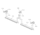
前記実施の形態では、第1取付部材5(ブラケット5A,5B)の取り付けの向きは、第1取付部材5の長手方向を車両長手方向と一致させているが、車両幅方向としてもよい。たとえば、図7及び図8に示すように、第1取付部材5(ブラケット5A,5B)は、取付部材長手方向が車両幅方向となるように、屋根構体21に形成され車両長手方向に延びる吊り溝21aに機械的締結具11Fを用いて位置調整して取り付ける。そして、第1ブラケット5A及び第2ブラケット5B(第1取付部材5)には、長穴5b,5dを設け、第1取付部材5と第2取付部材6とは機械的締結具11Gに締結される。このとき、長穴5b,5dを利用しているので、車両上下方向の位置調整が可能である。車両上下方向の位置調整後には、他の構成部材はリベットなどの固定具により固定される点は上述の実施の形態と同様である。そして第2取付部材6Aには、車両長手方向に配置される蛍光灯などの灯具7Aを支持するフレーム22が取り付けられ、取付部材を構成する板材が重複する部分に吊り手棒受け10Aが取り付けられるようにすればよい。
<
In the embodiment described above , the mounting direction of the first mounting member 5 (brackets 5A and 5B) is such that the longitudinal direction of the first mounting
1 屋根外板
4 屋根構体
5 第1取付部材
5b 長穴(貫通穴)
5d 長穴(貫通穴)
5A 第1ブラケット
5B 第2ブラケット
6,6A 第2取付部材
6a 鉛直部
6aa 屈曲延長部(屈曲部)
6ab 案内傾斜部
6ac 係合部(挿入部)
6c 水平部
6ca 屈曲挿入部
6cb 延長部
7 灯具
8 側天井
9 空調ダクト
10 吊り手棒受け
11A〜11G 機械的締結具(第1固定具)
12A,12B 内側部材
12Aa,12Ba 鉛直部
12Ab,12Bb 水平部
12Aba 屈曲延長部
12Bba 屈曲延長部(内側部材屈曲部)
12Bbc 案内傾斜部
S1 空所
S2 隙間
DESCRIPTION OF
5d slot (through hole)
5A 1st bracket 5B
6ab guide inclined part 6ac engaging part (insertion part)
6c Horizontal part 6ca Bending insertion part
12A, 12B inner member 12Aa, 12Ba Vertical portion 12Ab, 12Bb Horizontal portion 12Aba Bending extension portion 12Bba Bending extension portion (inner member bending portion)
12Bbc Guide slope part S1 Empty space S2 Clearance
Claims (10)
車両内装品を取付可能な水平部と、前記水平部の長辺側端部に設けられ、前記貫通穴を貫通する第1固定具により前記第1取付部材に対して上下方向に位置調整可能に取り付けられる鉛直部とを含む、隣接する少なくとも2つの第2取付部材とを備え、
前記第2取付部材が前記第1固定具により前記第1取付部材に対して仮締めされた状態で、隣接する前記第2取付部材の上下方向の位置が略一致するように調整される、鉄道車両の内装品取付構造。
1st attachment which can be attached to the roof structure of a railway vehicle, and has the one end part extended in a horizontal direction, and the other end part in which the through-hole extended in the vertical direction and extended in the up-down direction was formed. Members ,
And attachable horizontal portion of the vehicle interior equipment, provided on the long side end of the horizontal portion, adjustable in position in the vertical direction with respect to the first attachment member by a first fastener extending through the through hole And at least two adjacent second attachment members, each including a vertical portion attached to
The railway is adjusted so that the vertical positions of the adjacent second mounting members substantially coincide with each other in a state where the second mounting member is temporarily fastened to the first mounting member by the first fixture. Vehicle interior parts mounting structure.
さらに、前記第2取付部材が、前記第1取付部材に対して、せん断力により固定される第2固定具により固定される、請求項1に記載の鉄道車両の内装品取付構造。
After the vertical position of the second mounting member is adjusted, the second mounting member is fixed to the first mounting member by the first fixture,
Furthermore, the interior mounting structure for a railway vehicle according to claim 1 , wherein the second mounting member is fixed to the first mounting member by a second fixing member that is fixed by a shearing force .
前記第2ブラケットは、長手方向の長さが前記第1ブラケットの長手方向の長さよりも長く、
前記第1ブラケット及び第2ブラケットは、前記第2取付部材の長辺側端部に設けられた各前記鉛直部を支持する、請求項1又は2に記載の鉄道車両の内装品取付構造。 The first mounting member includes at least a first bracket and a second bracket,
The second bracket has a length in the longitudinal direction longer than a length in the longitudinal direction of the first bracket,
3. The interior mounting structure for a railway vehicle according to claim 1, wherein the first bracket and the second bracket support the vertical portions provided at end portions on the long side of the second mounting member.
隣接する各前記第2取付部材は、1つの前記第1取付部材により連結される、請求項1〜3のいずれか1つに記載の鉄道車両の内装品取付構造。 The plurality of second mounting members are continuously arranged along the longitudinal direction of the second mounting member ,
The interior part attachment structure for a railway vehicle according to any one of claims 1 to 3 , wherein each of the adjacent second attachment members is connected by one of the first attachment members .
前記屈曲部と前記鉛直部との間には、空所が形成され、
隣接する各前記第2取付部材のうち、一方の前記第2取付部材側に形成された前記挿入部が、他方の前記第2取付部材側の前記空所に挿入されて連結される、請求項4に記載の鉄道車両の内装品取付構造。 The second attachment member is bent outward at the short side end of the vertical portion and extends in the longitudinal direction of the second attachment member , and extends in the longitudinal direction of the vertical portion at the other end. An insertion portion,
A void is formed between the bent portion and the vertical portion,
Of the adjacent respective said second attachment member, the insertion portion formed on one of the second mounting member side is connected is inserted into the cavity of the other of the second mounting member side, claim 4. An interior mounting structure for a railway vehicle according to 4 .
前記第2取付部材は、前記水平部の短辺側端部に、車両上部方向に屈曲して前記第2取付部材の長手方向に延びる屈曲挿入部と、他端に前記第2取付部材の長手方向に延びる延長部とを有し、
前記内側部材の一端には、車両上部方向に屈曲して前記第2取付部材の長手方向に延びる内側部材屈曲部を有し、
前記内側部材屈曲部と前記延長部との間には、隙間が形成され、
隣接する各前記第2取付部材のうち、一方の前記第2取付部材側に形成された前記屈曲挿入部が、他方の前記第2取付部材側に形成された前記隙間に挿入されて連結される、請求項4又は5に記載の鉄道車両の内装品取付構造。 On the second mounting member, further comprising an inner member at the short side end of the second mounting member ,
The second attachment member includes a bent insertion portion that is bent in the vehicle upper direction at the short side end portion of the horizontal portion and extends in the longitudinal direction of the second attachment member , and the longitudinal direction of the second attachment member at the other end. An extension extending in the direction,
One end of the inner member has an inner member bent portion that is bent in the vehicle upper direction and extends in the longitudinal direction of the second mounting member ,
A gap is formed between the inner member bent portion and the extension portion,
Of the adjacent respective said second attachment member, the bent insertion portion formed on one of the second mounting member side is connected is inserted into the gap formed in the other of the second mounting member side The interior mounting structure for a railway vehicle according to claim 4 or 5 .
前記隣接する第2取付部材の間であって、前記内側部材と前記第2取付部材との重合部には吊り手棒受けを取り付け可能である、請求項6又は7に記載の鉄道車両の内装品取付構造。 The horizontal portion of the second mounting member corresponds to the length of the lamp and is capable of mounting the lamp.
The interior of the railway vehicle according to claim 6 or 7 , wherein a suspension bar support can be attached between the adjacent second attachment members, and a overlapping portion between the inner member and the second attachment member. Product mounting structure.
Priority Applications (5)
| Application Number | Priority Date | Filing Date | Title |
|---|---|---|---|
| JP2010277578A JP5759712B2 (en) | 2010-12-14 | 2010-12-14 | Rail vehicle interior mounting structure |
| CN201180057220.2A CN103221288B (en) | 2010-12-14 | 2011-12-09 | The internal unit mounting structure of railway vehicle |
| US13/994,432 US9238469B2 (en) | 2010-12-14 | 2011-12-09 | Interior equipment installation structure for railcar |
| PCT/JP2011/006892 WO2012081211A1 (en) | 2010-12-14 | 2011-12-09 | Interior article mounting structure for railway vehicle |
| TW100145735A TWI455837B (en) | 2010-12-14 | 2011-12-12 | Installation and construction of inner parts of railway vehicles |
Applications Claiming Priority (1)
| Application Number | Priority Date | Filing Date | Title |
|---|---|---|---|
| JP2010277578A JP5759712B2 (en) | 2010-12-14 | 2010-12-14 | Rail vehicle interior mounting structure |
Publications (3)
| Publication Number | Publication Date |
|---|---|
| JP2012126185A JP2012126185A (en) | 2012-07-05 |
| JP2012126185A5 JP2012126185A5 (en) | 2014-01-23 |
| JP5759712B2 true JP5759712B2 (en) | 2015-08-05 |
Family
ID=46244330
Family Applications (1)
| Application Number | Title | Priority Date | Filing Date |
|---|---|---|---|
| JP2010277578A Active JP5759712B2 (en) | 2010-12-14 | 2010-12-14 | Rail vehicle interior mounting structure |
Country Status (5)
| Country | Link |
|---|---|
| US (1) | US9238469B2 (en) |
| JP (1) | JP5759712B2 (en) |
| CN (1) | CN103221288B (en) |
| TW (1) | TWI455837B (en) |
| WO (1) | WO2012081211A1 (en) |
Families Citing this family (15)
| Publication number | Priority date | Publication date | Assignee | Title |
|---|---|---|---|---|
| DE102012204687A1 (en) * | 2012-03-23 | 2013-09-26 | Siemens Aktiengesellschaft | Rail vehicle with air conditioning duct in the roof area and method for building a roof area of a rail vehicle |
| JP5926627B2 (en) * | 2012-06-13 | 2016-05-25 | 川崎重工業株式会社 | Rail vehicles and door pockets |
| JP6069038B2 (en) * | 2013-03-08 | 2017-01-25 | 川崎重工業株式会社 | Railway vehicle lighting system and railway vehicle |
| CN103303326B (en) * | 2013-06-20 | 2015-10-28 | 南车南京浦镇车辆有限公司 | Multifunctional built-in hanging arm |
| CN103273933B (en) * | 2013-06-20 | 2015-10-28 | 南车南京浦镇车辆有限公司 | Intercity motor train unit carriage top inside components hanging method |
| JP6196536B2 (en) * | 2013-11-12 | 2017-09-13 | 株式会社総合車両製作所 | Railcar interior product mounting structure and interior product mounting method |
| CN103963793B (en) * | 2014-05-22 | 2017-05-17 | 南车株洲电力机车有限公司 | Locomotive longitudinal beam and tramcar |
| CN204110038U (en) * | 2014-09-15 | 2015-01-21 | 南车青岛四方机车车辆股份有限公司 | Train passenger compartment top board |
| CN104210501B (en) * | 2014-09-23 | 2016-08-24 | 中车南京浦镇车辆有限公司 | Track checking car passes through platform region build-in vehicle roof structure |
| JP6450150B2 (en) | 2014-11-05 | 2019-01-09 | 川崎重工業株式会社 | Railway car body |
| CN104442870A (en) * | 2014-12-01 | 2015-03-25 | 南车株洲电力机车有限公司 | Rail vehicle, illuminating lamp mechanism and illuminating lamp angle adjustment device |
| CN104527679B (en) * | 2014-12-25 | 2017-01-18 | 中车青岛四方机车车辆股份有限公司 | Middle roof modular structure in railway vehicle and railway vehicle |
| EP3168104B1 (en) * | 2015-11-16 | 2020-05-06 | Bombardier Transportation GmbH | Linear air diffuser module comprising a multifunctional support member for a car body of a public transportation vehicle |
| CN109204330B (en) * | 2018-08-29 | 2020-07-07 | 中车南京浦镇车辆有限公司 | Large-visual-field suspension type air rail train |
| JP6994095B1 (en) * | 2020-09-16 | 2022-01-14 | 日本車輌製造株式会社 | Railroad vehicle |
Family Cites Families (16)
| Publication number | Priority date | Publication date | Assignee | Title |
|---|---|---|---|---|
| US2925050A (en) * | 1957-01-09 | 1960-02-16 | Pullman Inc | Side frame construction and finish |
| US3035161A (en) * | 1960-06-06 | 1962-05-15 | Budd Co | Vehicle ceiling with lighting fixture |
| JPS53110219U (en) * | 1977-02-09 | 1978-09-04 | ||
| JPH04126660A (en) * | 1990-09-19 | 1992-04-27 | Hitachi Ltd | Inside panel arranging structure for vehicle |
| AU655250B2 (en) * | 1991-04-26 | 1994-12-08 | Hitachi Limited | Vehicle and method of producing the same |
| JPH07172306A (en) | 1993-09-20 | 1995-07-11 | Hitachi Ltd | Rolling stock and its interior outfitting method |
| KR950008262A (en) * | 1993-09-20 | 1995-04-17 | 가나이 쯔도무 | Railway vehicle and its interior decoration method |
| AU6136996A (en) * | 1996-06-19 | 1998-01-07 | Hitachi Limited | Vehicle, side structure for vehicles, and method of manufacturing the same |
| JP3658900B2 (en) * | 1996-12-18 | 2005-06-08 | 株式会社日立製作所 | Railroad car ceiling interior equipment |
| JP3027576B1 (en) | 1999-02-09 | 2000-04-04 | 川崎重工業株式会社 | Vehicle interior panel mounting structure |
| JP3038215B1 (en) * | 1999-08-30 | 2000-05-08 | 川崎重工業株式会社 | Railcar interior panel mounting structure |
| JP2001171516A (en) * | 1999-12-17 | 2001-06-26 | Kinki Sharyo Co Ltd | Mounting method of rolling stock interior ceiling plate |
| JP2002356162A (en) | 2001-03-29 | 2002-12-10 | Nippon Sharyo Seizo Kaisha Ltd | Interior equipment mounting structure for railway car |
| DE10321661A1 (en) * | 2003-05-14 | 2004-12-09 | Siemens Ag | Roof-side interior cladding of a spacious vehicle for the transportation of people, in particular a rail vehicle |
| JP4324446B2 (en) * | 2003-10-27 | 2009-09-02 | 東急車輛製造株式会社 | Vehicle outfitting structure |
| JP4286258B2 (en) * | 2005-03-17 | 2009-06-24 | 株式会社日立製作所 | Rail vehicle |
-
2010
- 2010-12-14 JP JP2010277578A patent/JP5759712B2/en active Active
-
2011
- 2011-12-09 US US13/994,432 patent/US9238469B2/en active Active
- 2011-12-09 CN CN201180057220.2A patent/CN103221288B/en active Active
- 2011-12-09 WO PCT/JP2011/006892 patent/WO2012081211A1/en active Application Filing
- 2011-12-12 TW TW100145735A patent/TWI455837B/en active
Also Published As
| Publication number | Publication date |
|---|---|
| WO2012081211A1 (en) | 2012-06-21 |
| US20130319282A1 (en) | 2013-12-05 |
| CN103221288B (en) | 2015-12-16 |
| TW201240850A (en) | 2012-10-16 |
| CN103221288A (en) | 2013-07-24 |
| US9238469B2 (en) | 2016-01-19 |
| TWI455837B (en) | 2014-10-11 |
| JP2012126185A (en) | 2012-07-05 |
Similar Documents
| Publication | Publication Date | Title |
|---|---|---|
| JP5759712B2 (en) | Rail vehicle interior mounting structure | |
| JP2012126185A5 (en) | ||
| JP5295406B2 (en) | Railcar ceiling structure | |
| CN103857557A (en) | Seat assembly having a front cushion module | |
| JP5859858B2 (en) | Railroad vehicle equipment mounting structure | |
| US9067624B2 (en) | Cross member for a frame of a vehicle as well as frame for a vehicle | |
| JP2006240420A (en) | Vehicular cross member, frame structure and roof structure | |
| EP3202613A1 (en) | Seat mount for displaceable attachment to a railway vehicle floor | |
| JP6196536B2 (en) | Railcar interior product mounting structure and interior product mounting method | |
| WO2016072043A1 (en) | Railway vehicle body | |
| CN103052585B (en) | Guiding boots and the elevator that is provided with the guiding boots that slide slide | |
| CN112977506B (en) | Rail vehicle and modular middle top plate structure thereof | |
| EP1731410B1 (en) | Steering support member structure | |
| JP3658900B2 (en) | Railroad car ceiling interior equipment | |
| JPH07172306A (en) | Rolling stock and its interior outfitting method | |
| US11260774B2 (en) | Modular transportation seat frame | |
| RU2664811C2 (en) | Fastening arrangement of radiator trim and bumper on front support of motor vehicle | |
| JP2626371B2 (en) | Car body | |
| CN104340275B (en) | Structure for connection of elements of vehicle front | |
| JP5704310B2 (en) | Bus floor structure | |
| JP2015519238A (en) | Structure for installing the driver's seat of a vehicle | |
| JP7351709B2 (en) | Railway vehicle interior parts installation structure | |
| CN213262292U (en) | Front bumper installing support assembly and vehicle | |
| JP7141186B2 (en) | Ceiling panel mounting structure for railway vehicle and railway vehicle | |
| JP7379187B2 (en) | Railway vehicle side ceiling panel |
Legal Events
| Date | Code | Title | Description |
|---|---|---|---|
| A521 | Request for written amendment filed |
Free format text: JAPANESE INTERMEDIATE CODE: A523 Effective date: 20131203 |
|
| A621 | Written request for application examination |
Free format text: JAPANESE INTERMEDIATE CODE: A621 Effective date: 20131203 |
|
| A131 | Notification of reasons for refusal |
Free format text: JAPANESE INTERMEDIATE CODE: A131 Effective date: 20141111 |
|
| A521 | Request for written amendment filed |
Free format text: JAPANESE INTERMEDIATE CODE: A523 Effective date: 20141224 |
|
| TRDD | Decision of grant or rejection written | ||
| A01 | Written decision to grant a patent or to grant a registration (utility model) |
Free format text: JAPANESE INTERMEDIATE CODE: A01 Effective date: 20150512 |
|
| A61 | First payment of annual fees (during grant procedure) |
Free format text: JAPANESE INTERMEDIATE CODE: A61 Effective date: 20150608 |
|
| R150 | Certificate of patent or registration of utility model |
Ref document number: 5759712 Country of ref document: JP Free format text: JAPANESE INTERMEDIATE CODE: R150 |
|
| S111 | Request for change of ownership or part of ownership |
Free format text: JAPANESE INTERMEDIATE CODE: R313111 |
|
| R350 | Written notification of registration of transfer |
Free format text: JAPANESE INTERMEDIATE CODE: R350 |
|
| R250 | Receipt of annual fees |
Free format text: JAPANESE INTERMEDIATE CODE: R250 |