EP2380425B1 - Aufsitzmäher mit Keilriemenantrieb - Google Patents
Aufsitzmäher mit Keilriemenantrieb Download PDFInfo
- Publication number
- EP2380425B1 EP2380425B1 EP20110003189 EP11003189A EP2380425B1 EP 2380425 B1 EP2380425 B1 EP 2380425B1 EP 20110003189 EP20110003189 EP 20110003189 EP 11003189 A EP11003189 A EP 11003189A EP 2380425 B1 EP2380425 B1 EP 2380425B1
- Authority
- EP
- European Patent Office
- Prior art keywords
- belt
- profiles
- driving
- riding mower
- pulley
- Prior art date
- Legal status (The legal status is an assumption and is not a legal conclusion. Google has not performed a legal analysis and makes no representation as to the accuracy of the status listed.)
- Active
Links
Images


Classifications
-
- A—HUMAN NECESSITIES
- A01—AGRICULTURE; FORESTRY; ANIMAL HUSBANDRY; HUNTING; TRAPPING; FISHING
- A01D—HARVESTING; MOWING
- A01D34/00—Mowers; Mowing apparatus of harvesters
- A01D34/01—Mowers; Mowing apparatus of harvesters characterised by features relating to the type of cutting apparatus
- A01D34/412—Mowers; Mowing apparatus of harvesters characterised by features relating to the type of cutting apparatus having rotating cutters
- A01D34/63—Mowers; Mowing apparatus of harvesters characterised by features relating to the type of cutting apparatus having rotating cutters having cutters rotating about a vertical axis
- A01D34/64—Mowers; Mowing apparatus of harvesters characterised by features relating to the type of cutting apparatus having rotating cutters having cutters rotating about a vertical axis mounted on a vehicle, e.g. a tractor, or drawn by an animal or a vehicle
Definitions
- the invention relates to a Tarsitzffleher V-belt drive, comprising a support structure with two longitudinal sides, a drive motor, a transmission and a V-belt drive with at least one drive V-belt and a plurality of pulleys for this drive V-belt for frictional connection between the drive motor and transmission.
- a similar ride-on mower in which a driving gear is driven by means of a motor, wherein a V-belt drive is used for power transmission between the engine and driving gear, is from the document US-A-2003/0000191 known.
- a problem with such V-belt driven riding mowers is that the user of this ride-on mower and sometimes even people around the user are at risk from the V-belt drive as soon as they get their extremities under the chassis of the ride-on mower. There is a risk that hands or feet get through the fast-moving drive V-belt, for example, between the pulley and the drive V-belt itself, which can cause serious injury.
- the inventors have recognized that it is possible to lay the V-belt drive in the protection of already existing longitudinal members in the supporting structure, so that the current drive V-belt is covered so far that no accidental Hineinippo in the current drive V-belt is possible.
- the drive V-belt is guided with the help of appropriately arranged pulleys over most of the way of his run so in the range of L and / or C-profiles, that the drive V-belt is no longer directly accessible from the outside.
- cavity does not mean a closed cavity, but rather a virtual imaginary rectangular cavity which is defined by the limbs of the L or C profile.
- the drive V-belt can be guided substantially parallel along the profiles and disappears in this way over a relatively long distance in the rectangular cavity formed by these.
- the at least one deflection roller it may be particularly advantageous, if it is arranged in the region of the lateral profiles, that the free distance between the at least one deflection roller and a leg of the profile parallel to the axis of rotation of the at least one deflection roller is smaller , than the V-belt height of the drive V-belt.
- a further advantageous embodiment of the Aufsitzmähers invention provides that at least one of the deflection rollers is fixed with its axis of rotation directly to a leg of the L or C profiles.
- FIG. 1 shows an oblique view of a three-dimensional illustrated support structure 1 of a Aufsitzfflehers invention.
- the support structure 1 consists essentially of two laterally extending C-profiles 8, to which a seat support 13 is mounted in the rear region, in the front region a motor support 12 which connects the two C-profiles 8, and approximately in the middle of the support structure , Left and right to the C-profiles, one foot plate 14 is arranged.
- FIG. 2 is a side view of this support structure 1 with the seat support 13, the front mounted engine mount 12 and the toe 14, which is attached to the laterally disposed C-profile 8 shown. Also marked are two sections AA and BB, which are in the FIGS. 4 and 5 to be shown.
- FIG. 3 shows the support structure 1 in a plan view with the front engine mount 12 and the laterally arranged disorderblechen 14.
- an eruption in the field of V-belt drive is shown, in which the four pulleys 4.1 to 4.4 can be seen.
- the drive V-belt 3 which runs in the region of the C-profiles 8, also seen.
- the longitudinal axis 6 is shown, to which the laterally extending C-profiles 8 are arranged in mirror image with inwardly open profile.
- FIG. 4 shows the inventive course of the drive V-belt 3 in section AA from the FIG. 2 ,
- C-profiles 8 can be seen, wherein the drive V-belt 3 extends forward to the dashed lines indicated motor-side V-belt pulley 9, from there via the pulleys 4.2 and 4.3 in the from C Profile covered cavity is guided and is guided to the rear to the pulleys 4.1 and 4.4, from where it wraps around the transmission-side V-belt pulley 10.
- the pulley 4.4 shown here is spring-mounted and therefore acts as a tension pulley for the V-belt drive.
- section BB can be seen through the support structure 1, which is particularly good to see how the drive V-belt 3 runs on the left and right side 2.1, 2.2 of the support structure 1 within the cover by the C-profile 8 and thereby of unintentional access is protected.
- FIG. 5 also shows a detail C, which in the FIG. 6 is shown in more detail.
- This guide roller 4.2 is supported by a rotation axis which is fixed to the lower leg 8.1 of the C-profile 8.
- the attachment is carried out such that the distance 15 between the guide roller 4.2 and the lateral leg 8.2 of the C-profile fails smaller than the V-belt height 16 of the drive V-belt 3, so that it does not come out of the leadership of the pulley even with a release of the belt tension 4.2 can escape.
- FIGS. 7 and 8 Complementary in the FIGS. 7 and 8 again the cavity shown in phantom, which is formed by the legs 7.1 and 7.2 or 8.1., 8.2 and 8.3 of the L-profile 7 and the C-profile 8 and within which the drive V-belt according to the invention should be located at least over part of its route.
Landscapes
- Life Sciences & Earth Sciences (AREA)
- Environmental Sciences (AREA)
- Devices For Conveying Motion By Means Of Endless Flexible Members (AREA)
Description
- Die Erfindung betrifft einen Aufsitzmäher mit Keilriemenantrieb, aufweisend eine Tragkonstruktion mit zwei Längsseiten, einen Antriebsmotor, ein Getriebe und einen Keilriemenantrieb mit mindestens einem Antriebskeilriemen und mehreren Umlenkrollen für diesen Antriebskeilriemen zur kraftschlüssigen Verbindung zwischen Antriebsmotor und Getriebe.
- Ein ähnlicher Aufsitzmäher, bei denen ein Fahrgetriebe mit Hilfe eines Motors angetrieben wird, wobei zur Kraftübertragung zwischen Motor und Fahrgetriebe ein Keilriemenantrieb verwendet wird, ist aus der Druckschrift
US-A-2003/0000191 bekannt. Ein Problem bei solchen keilriemenangetriebenen Aufsitzmähern besteht darin, dass der Nutzer dieses Aufsitzmähers und manchmal auch Personen im Umkreis des Nutzers durch den Keilriemenantrieb gefährdet sind, sobald sie mit ihren Extremitäten unter das Chassis des Aufsitzmähers gelangen. Es besteht dabei die Gefahr, dass Hände oder Füße durch den schnell bewegten Antriebskeilriemen zum Beispiel zwischen die Umlenkrolle und den Antriebskeilriemen selbst gelangen, wodurch schwerste Verletzungen entstehen können. - Grundsätzlich ist es zwar möglich, einen separaten Keilriemenschutz anzubringen, der jeglichen Zugriff auf den Antriebskeilriemen verhindert, jedoch sind die Aufwendungen hierfür relativ groß, so dass andere Wege gesucht werden.
- Es ist daher Aufgabe der Erfindung einen Aufsitzmäher mit Keilriemenantrieb zu finden, welcher derart gestaltet ist, dass ohne besondere Abdeckfläche beziehungsweise zumindest durch eine verringerte Anzahl von Abdeckflächen ein ausreichender Schutz der Betreiber und sonstiger Personen gegen mögliche Verletzungen durch den Keilriemenantrieb gewährleistet ist.
- Diese Aufgabe wird durch die Merkmal des unabhängigen Patentanspruches gelöst. Vorteilhafte Weiterbildungen der Erfindung sind Gegenstand untergeordneter Ansprüche.
- Die Erfinder haben erkannt, dass es möglich ist, den Keilriemenantrieb in den Schutz von ohnehin bestehenden Längsträgern in der Tragkonstruktion zu verlegen, so dass der laufende Antriebskeilriemen soweit abgedeckt ist, dass kein unbeabsichtigtes Hineingreifen in den laufenden Antriebskeilriemen möglich ist. Hierzu wird der Antriebskeilriemen mit Hilfe von entsprechend angeordneten Umlenkrollen über den größten Teil des Weges seines Laufes derart im Bereich von L- und/oder C-Profilen geführt, dass der Antriebskeilriemen nicht mehr direkt von außen zugänglich ist.
- Entsprechend diesem Grundgedanken schlagen die Erfinder einen Aufsitzmäher mit einer Tragkonstruktion mit zwei Längsseiten, einem Antriebsmotor, einem Getriebe und einem Keilriemenantrieb mit mindestens einem Antriebskeilriemen und mehreren Umlenkrollen für diesen Antriebskeilriemen zur kraftschlüssigen Verbindung zwischen Antriebsmotor und Getriebe, vor, der dadurch verbessert ist, dass:
- die Tragkonstruktion zwei an den Längsseiten seitlich verlaufende L- oder C-Profile aufweist, wobei jedes Profil einen rechteckigen länglichen Hohlraum beschreibt und die derart spiegelbildlich zu einer senkrechten Ebene entlang der Längsachse der Tragkonstruktion so ausgerichtet sind, dass jeweils ein Schenkel an der Außenseite und ein Schenkel an der Unterseite verläuft, und
- die Umlenkrollen derart angeordnet sind, dass zumindest ein Teil des Antriebskeilriemens entlang der seitlich verlaufenden L- oder C-Profile und innerhalb eines von den Schenkeln der L- oder C-Profile jeweils umfassten rechteckigen Hohlraumes und außerdem der größte Teil der Länge des Antriebskeilriemens innerhalb der von den Profilen gebildeten Hohlräume verläuft.
- Bei einer solchen Ausführung eines Aufsitzmähers verläuft der Antriebskeilriemen geschützt außerhalb der Zugriffsmöglichkeit durch den Bediener beziehungsweise dritte Personen.
- Vorteilhaft ist es dabei, wenn nicht nur ein Teil, sondern der größte Teil der Länge des Antriebskeilriemens innerhalb der von den Profilen gebildeten Hohlräume verläuft.
- Es wird aber darauf hingewiesen, dass unter Hohlraum kein geschlossener Hohlraum zu verstehen ist, sondern jeweils ein virtuell gedachter rechteckiger Hohlraum, der durch die Schenkel des L- beziehungsweise C-Profils definiert ist.
- Vorteilhaft ist es bei dieser Ausführung des Aufsitzmähers, wenn der Antriebskeilriemen motorseitig eine Keilriemenscheibe, getriebeseitig eine weitere Keilriemenscheibe und dazwischen mehrere Umlenkrollen zumindest teilweise umschließt.
- Werden neben der motorseitigen und der getriebeseitigen Keilriemenscheibe genau vier Umlenkrollen verwendet, so kann der Antriebskeilriemen weitgehend parallel entlang der Profile geführt werden und verschwindet auf diese Weise über eine relativ lange Strecke in dem von diesen gebildeten rechteckigen Hohlraum.
- Für den Fall, dass eine Spannrolle im Verlauf des Antriebskeilriemens notwendig ist, besteht die Möglichkeit, eine der Umlenkrollen als Spannrolle auszuführen.
- Bezüglich der Ausgestaltung beziehungsweise Anordnung der mindestens einen Umlenkrolle kann es besonders vorteilhaft sein, wenn diese derart im Bereich der seitlichen Profile angeordnet ist, dass der freie Abstand zwischen der mindestens einen Umlenkrolle und einem parallel zur Rotationsachse der mindestens einen Umlenkrolle stehenden Schenkel des Profils kleiner ist, als die Keilriemenhöhe des Antriebskeilriemens.
- Durch diese Ausführung wird ein Antriebskeilriemen, der einmal auf die Umlenkrollen aufgelegt wurde, zwischen den Schenkel des Profils und dem Profil der Umlenkrolle sicher gehalten und kann so lange er nicht stark beschädigt beziehungsweise zerrissen wird, nicht mehr aus seiner Führung herausspringen. Durch diese Ausführung werden die sonst üblichen Klammern, die das Herausspringen des Antriebskeilriemens von der Umlenkrolle verhindern sollen, eingespart.
- Da in den meisten Fällen der Antriebskeilriemen im Bereich der motorseitigen Keilriemenscheibe beziehungsweise im Bereich der getriebenseitigen Keilriemenscheibe zur Mittelachse des Aufsitzmähers gelenkt werden muss, muss er dort auch zwangsläufig den Bereich der L- oder C-Profile verlassen, so dass dort eventuell ein zusätzliches Abdeckblech angebracht werden sollte.
- Eine weitere vorteilhafte Ausgestaltung des erfindungsgemäßen Aufsitzmähers sieht vor, dass zumindest eine der Umlenkrollen mit ihrer Drehachse unmittelbar an einem Schenkel der L- oder C-Profile befestigt ist. Durch diese Ausgestaltung können zusätzliche Haltewinkel oder ähnliche Halterungen eingespart werden und damit für eine günstige Produktion gesorgt werden.
- Im Folgenden wird die Erfindung anhand eines bevorzugten Ausführungsbeispieles mit Hilfe der Figuren näher beschrieben, wobei nur die zum Verständnis der Erfindung notwendigen Merkmale dargestellt sind.
- Es zeigen im Einzelnen:
- FIG 1:
- 3D-Ansicht einer Tragkonstruktion eines Aufsitzmähers;
- FIG 2:
- Seitenansicht der Tragkonstruktion eines Aufsitzmähers;
- FIG 3:
- Aufsicht von oben auf die Tragkonstruktion aus
FIG 1 mit einem Ausbruch im Bereich der Antriebskeilriemenführung nahe den Längsprofilen; - FIG 4:
- Schnitt A-A aus
FIG 2 ; - FIG 5:
- Schnitt B-B aus
FIG 2 ; - FIG 6:
- Detail C aus der
FIG 5 ; - FIG 7:
- L-Profil mit umschlossenem rechteckigen Hohlraum;
- FIG 8:
- C-Profil-mit umschlossenem rechteckigen Hohlraum.
- Die
Figur 1 zeigt eine schräge Ansicht einer dreidimensionalen dargestellten Tragkonstruktion 1 eines erfindungsgemäßen Aufsitzmähers. Die Tragkonstruktion 1 besteht im Wesentlichen aus zwei seitlich verlaufenden C-Profilen 8, an denen im hinteren Bereich ein Sitzträger 13 angebracht ist, im vorderen Bereich ein Motorträger 12, der die beiden C-Profile 8 verbindet, und etwa in der Mitte der Tragkonstruktion 1, links und rechts an den C-Profilen, jeweils ein Fußblech 14 angeordnet ist. - In der
Figur 2 ist eine Seitenansicht dieser Tragkonstruktion 1 mit dem Sitzträger 13, dem vorne angeordneten Motorträger 12 und dem Fußblech 14, welches an dem seitlich angeordneten C-Profil 8 befestigt ist, gezeigt. Eingezeichnet sind des Weiteren zwei Schnitte A-A und B-B, die in denFiguren 4 und5 gezeigt werden. - Die
Figur 3 zeigt die Tragkonstruktion 1 in einer Draufsicht mit dem vorne liegenden Motorträger 12 und den seitlich angeordneten Fußblechen 14. Zur Darstellung der Erfindung ist ein Ausbruch im Bereich des Keilriemenantriebs gezeigt, in dem die vier Umlenkrollen 4.1 bis 4.4 zu erkennen sind. Des Weiteren ist der Antriebskeilriemen 3, der im Bereich der C-Profile 8 verläuft, ebenfalls zu sehen. Zusätzlich ist die Längsachse 6 eingezeichnet, zu der die seitlich verlaufenden C-Profile 8 spiegelbildlich mit nach innen offenem Profil angeordnet sind. - Die
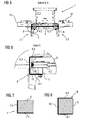
Figur 4 zeigt den erfindungsgemäß Verlauf des Antriebskeilriemens 3 im Schnitt A-A aus derFigur 2 . Es sind wieder die an der linken Seite 2.1 und rechten Seite 2.2 der Tragkonstruktion 1 angeordneten C-Profile 8 zu erkennen, wobei der Antriebskeilriemen 3 vorne um die gestrichelt angedeutete motorseitige Keilriemenscheibe 9 verläuft, von dort über die Umlenkrollen 4.2 und 4.3 in den vom C-Profil abgedeckten Hohlraum geführt wird und nach hinten zu den Umlenkrollen 4.1 und 4.4 geführt wird, von wo aus er die getriebeseitige Keilriemenscheibe 10 umschlingt. Die hier gezeigte Umlenkrolle 4.4 ist federnd gelagert und wirkt daher als Spannrolle für den Keilriemenantrieb. - In der
Figur 5 ist der Schnitt B-B durch die Tragkonstruktion 1 zu erkennen, wobei hier besonders gut zu sehen ist, wie der Antriebskeilriemen 3 auf der linken und rechen Seite 2.1, 2.2 der Tragkonstruktion 1 innerhalb der Abdeckung durch das C-Profil 8 verläuft und dadurch von unbeabsichtigten Zugriffen geschützt ist. - Die
Figur 5 zeigt auch ein Detail C, welches in derFigur 6 näher dargestellt ist. Hier ist vergrößert der Bereich der Anordnung einer Umlenkrolle 4.2 innerhalb des C-Profils 8 zu erkennen. Diese Umlenkrolle 4.2 wird durch eine Drehachse gelagert, die am unteren Schenkel 8.1 des C-Profils 8 befestigt ist. Die Befestigung ist dabei derart ausgeführt, dass der Abstand 15 zwischen der Umlenkrolle 4.2 und dem seitlichen Schenkel 8.2 des C-Profils kleiner ausfällt, als die Keilriemenhöhe 16 des Antriebskeilriemens 3, so dass dieser auch bei einem Lösen der Keilriemenspannung nicht aus der Führung der Umlenkrolle 4.2 entweichen kann. - Ergänzend ist in den
Figuren 7 und 8 nochmals der Hohlraum gestrichelt dargestellt, der durch die Schenkel 7.1 und 7.2 beziehungsweise 8.1., 8.2 und 8.3 des L-Profils 7 beziehungsweise des C-Profils 8 gebildet wird und innerhalb denen sich der Antriebskeilriemen erfindungsgemäß zumindest über einen Teil seiner Strecke befinden soll. - Durch die erfindungsgemäße Ausgestaltung des Aufsitzrasenmähers, insbesondere die Anordnung seines Keilriermenantriebs innerhalb der Tragkonstruktion wird damit also erreicht, dass ohne besonderen zusätzlichen Kosten eine Führung des Antriebskeilriemens derart erreicht wird, dass dieser entsprechend geschützt verläuft und damit eine Verletzungsgefahr drastisch verringert wird.
-
- 1
- Tragkonstruktion
- 2.1
- linke Längsseite
- 2.2
- rechte Längsseite
- 3
- Antriebskeilriemen
- 4.1-4.4
- Umlenkrollen
- 5
- Hohlraum
- 6
- Längsachse
- 7
- L-Profil
- 7.1,7.2
- Schenkel des L-Profils
- 8
- C-Profil
- 8.1,8.2,8.3
- Schenkel des C-Profils
- 9
- Keilriemenscheibe motorseitig
- 10
- Keilriemenscheibe getriebeseitig
- 11
- Drehachse einer Umlenkrolle
- 12
- Motorträger
- 13
- Sitzträger
- 14
- Fußbleche
- 15
- Abstand Umlenkrolle - Profilschenkel
- 16
- Höhe des Antriebskeilriemens
Claims (7)
- Aufsitzmäher aufweisend:1.1. eine Tragkonstruktion, (1) mit zwei Längsseiten (2.1, 2.2),1.2. einen Antriebsmotor,1.3. ein Getriebe,1.4. einen Keilriemenantrieb mit mindestens einem Antriebskeilriemen (3) und mehreren Umlenkrollen (4.4-4.4) für diesen Antriebskeilriemen (3) zur kraftschlüssigen Verbindung zwischen Antriebsmotor und Getriebe,
dadurch gekennzeichnet, dass1.5. die Tragkonstruktion (1) zwei an den Längsseiten (2.1, 2.2) seitlich verlaufende L- oder C-Profile aufweist, wobei jedes Profil einen rechteckigen länglichen Hohlraum (5) beschreibt und die derart spiegelbildlich zu einer senkrechten Ebene entlang der Längsachse (6) der Tragkonstruktion (1) so ausgerichtet sind, dass jeweils ein Schenkel (7.2, 8.2) an der Außenseite und ein Schenkel an der Unterseite (7.1, 8.1) verläuft,1.6. die Umlenkrollen (4.1-4.4) derart angeordnet sind, dass zumindest ein Teil des Antriebskeilriemens (3) entlang der seitlich verlaufenden L- oder C-Profile (7, 8) und innerhalb eines von den Schenkeln (7.1, 7.2, 8.1, 8.2, 8.3) der L- oder C-Profile (7, 8) jeweils umfassten rechteckigen Hohlraumes (5) und außerdem der größte Teil der Länge des Antriebskeilriemens (3) innerhalb der von den Profilen gebildeten Hohlräume (5) verläuft. - Aufsitzmäher gemäß dem voranstehenden Patentanspruch 1, dadurch gekennzeichnet, dass, der Antriebskeilriemen (3) motorseitig eine Keilriemenscheibe (9), getriebeseitig eine Keilriemenscheibe (10) und dazwischen mehrere Umlenkrollen (4.1-4.4) zumindest teilweise umschließt.
- Aufsitzmäher gemäß dem voranstehenden Patentanspruch 2, dadurch gekennzeichnet, dass genau vier Umlenkrollen (4.1-4.4) vorgesehen sind, die den Antriebskeilriemen (3) entlang der Profile führen.
- Aufsitzmäher gemäß einem der voranstehenden Patentansprüche 1 bis 3, dadurch gekennzeichnet , dass eine der Umlenkrollen als Spannrolle (4.4) ausgeführt ist.
- Aufsitzmäher (1) gemäß einem der voranstehenden Patentansprüche 1 bis 4, dadurch gekennzeichnet dass mindestens eine Umlenkrolle (4.1.-4.4) derart im Bereich der seitlichen Profile (8) angeordnet ist, dass der freie Abstand (15) zwischen der mindestens einen Umlenkrolle (4.2) und einem parallel zur Rotationsachse der mindestens einen Umlenkrolle (4.2) stehenden Schenkel (8.2) des Profils kleiner ist, als die Keilriemenhöhe des Antriebskeilriemens (3).
- Aufsitzmäher gemäß einem der voranstehenden Patentansprüche 1 bis 5, dadurch gekennzeichnet, dass in dem Bereich, in dem der Antriebskeilriemen (3) nicht in den Profilen (8) verläuft, ein Abdeckblech vorgesehen ist, welches einen freien Zugriff auch den Antriebskeilriemen (3) von unten verhindert.
- Aufsitzmäher gemäß einem der voranstehenden Patentansprüche 1 bis 6, dadurch gekennzeichnet, dass zumindest eine der Umlenkrollen (4.1-4.4) mit ihrer Drehachse (11) unmittelbar an einem Schenkel (8.1) der L- oder C-Profile (7, 8) befestigt ist.
Applications Claiming Priority (1)
| Application Number | Priority Date | Filing Date | Title |
|---|---|---|---|
| DE201010017989 DE102010017989A1 (de) | 2010-04-21 | 2010-04-21 | Aufsitzmäher mit Keilriemenantrieb |
Publications (2)
| Publication Number | Publication Date |
|---|---|
| EP2380425A1 EP2380425A1 (de) | 2011-10-26 |
| EP2380425B1 true EP2380425B1 (de) | 2013-02-20 |
Family
ID=44117084
Family Applications (1)
| Application Number | Title | Priority Date | Filing Date |
|---|---|---|---|
| EP20110003189 Active EP2380425B1 (de) | 2010-04-21 | 2011-04-15 | Aufsitzmäher mit Keilriemenantrieb |
Country Status (2)
| Country | Link |
|---|---|
| EP (1) | EP2380425B1 (de) |
| DE (1) | DE102010017989A1 (de) |
Family Cites Families (5)
| Publication number | Priority date | Publication date | Assignee | Title |
|---|---|---|---|---|
| US4882940A (en) * | 1985-06-12 | 1989-11-28 | Kanzaki Kokyukoki Mfg. Co. Ltd. | Power transmission mechanism for tractor |
| US4787646A (en) * | 1987-05-07 | 1988-11-29 | Simplicity Manufacturing, Inc. | Riding mower chassis with floating steerable rear wheels |
| US6427430B1 (en) * | 2000-08-15 | 2002-08-06 | Deere & Company | Pedal lift system for lawn tractor mower deck |
| US6651413B2 (en) * | 2001-07-02 | 2003-11-25 | Exmark Manufacturing Company, Incorporated | Multiple belt mule drive apparatus and systems/vehicles using same |
| ITMI20080397U1 (it) * | 2008-12-03 | 2010-06-04 | Ggp Italy Spa | Telaio per trattorino rasaerba |
-
2010
- 2010-04-21 DE DE201010017989 patent/DE102010017989A1/de not_active Withdrawn
-
2011
- 2011-04-15 EP EP20110003189 patent/EP2380425B1/de active Active
Also Published As
| Publication number | Publication date |
|---|---|
| DE102010017989A1 (de) | 2011-10-27 |
| EP2380425A1 (de) | 2011-10-26 |
Similar Documents
| Publication | Publication Date | Title |
|---|---|---|
| DE102009005592B3 (de) | Doppelkettenzuganordnung | |
| DE602005001952T2 (de) | Teleskopisch ausfahrbarer Bandförderer | |
| EP2388215B1 (de) | Umlenkvorrichtung für ein Fördersystem | |
| DE102010030840A1 (de) | Schneidwerk mit verstellbarem Schneidbalken | |
| DE102011080385B3 (de) | Mähdeck | |
| DE202007015508U1 (de) | Mobilisierungshilfe für in ihren Bewegungsmöglichkeiten beeinträchtigte Personen | |
| DE102011008723A1 (de) | Erntevorsatz für eine Erntemaschine | |
| EP0747303A1 (de) | Stabband für Stabbandförderer | |
| DE102016213255A1 (de) | Mähwerkeinstellradstütze | |
| DE69515651T2 (de) | Fahrgestell bauweise | |
| DE102014108288A1 (de) | Förderkette | |
| DE602004007757T2 (de) | Teleskopisch ausfahrbarer Bandförderer | |
| DE2419546B2 (de) | Schrank mit herausziehbaren schubladenelementen | |
| EP2380425A1 (de) | Aufsitzmaeher mit Keilriemenantrieb | |
| DE102004021708B4 (de) | Vereinfachte Katze mit niedriger Bauhöhe | |
| DE102014107206A1 (de) | Umklappbares Trampolin | |
| DE202016102670U1 (de) | Rollbares Tragenetz für Fenster und Türen | |
| WO1985004153A1 (fr) | Installation pour proteger les ouvertures situees a l'entree ou a la sortie de l'installation de transport dans des convoyeuses a bande | |
| DE3316966C2 (de) | Antriebsvorrichtung für einen mehrreihigen Maismäh- und/oder Pflückhäcksler | |
| DE69000333T2 (de) | Versteckbare luftausstroemeinrichtung. | |
| DE102016112052A1 (de) | Ährenheber | |
| EP0193186A1 (de) | Rasenmäher | |
| DE1278954C2 (de) | Rechenreinigungsanlage fuer einen stationaeren rechen | |
| DE10227743C2 (de) | Methode zur Montage von Führungen für Ausziehkörbe, die vorzugsweise für Küchenmöbel bestimmt sind | |
| DE202009008294U1 (de) | Gitterboden für einen Geflügelkäfig, insbesondere Broilerkäfig |
Legal Events
| Date | Code | Title | Description |
|---|---|---|---|
| AK | Designated contracting states |
Kind code of ref document: A1 Designated state(s): AL AT BE BG CH CY CZ DE DK EE ES FI FR GB GR HR HU IE IS IT LI LT LU LV MC MK MT NL NO PL PT RO RS SE SI SK SM TR |
|
| AX | Request for extension of the european patent |
Extension state: BA ME |
|
| PUAI | Public reference made under article 153(3) epc to a published international application that has entered the european phase |
Free format text: ORIGINAL CODE: 0009012 |
|
| 17P | Request for examination filed |
Effective date: 20111201 |
|
| 17Q | First examination report despatched |
Effective date: 20120202 |
|
| GRAP | Despatch of communication of intention to grant a patent |
Free format text: ORIGINAL CODE: EPIDOSNIGR1 |
|
| RAP1 | Party data changed (applicant data changed or rights of an application transferred) |
Owner name: AL-KO KOBER AG |
|
| GRAS | Grant fee paid |
Free format text: ORIGINAL CODE: EPIDOSNIGR3 |
|
| GRAA | (expected) grant |
Free format text: ORIGINAL CODE: 0009210 |
|
| AK | Designated contracting states |
Kind code of ref document: B1 Designated state(s): AL AT BE BG CH CY CZ DE DK EE ES FI FR GB GR HR HU IE IS IT LI LT LU LV MC MK MT NL NO PL PT RO RS SE SI SK SM TR |
|
| REG | Reference to a national code |
Ref country code: GB Ref legal event code: FG4D Free format text: NOT ENGLISH |
|
| REG | Reference to a national code |
Ref country code: CH Ref legal event code: EP |
|
| REG | Reference to a national code |
Ref country code: AT Ref legal event code: REF Ref document number: 597096 Country of ref document: AT Kind code of ref document: T Effective date: 20130315 |
|
| REG | Reference to a national code |
Ref country code: IE Ref legal event code: FG4D Free format text: LANGUAGE OF EP DOCUMENT: GERMAN |
|
| REG | Reference to a national code |
Ref country code: DE Ref legal event code: R096 Ref document number: 502011000411 Country of ref document: DE Effective date: 20130418 |
|
| REG | Reference to a national code |
Ref country code: NL Ref legal event code: VDEP Effective date: 20130220 |
|
| REG | Reference to a national code |
Ref country code: LT Ref legal event code: MG4D |
|
| PG25 | Lapsed in a contracting state [announced via postgrant information from national office to epo] |
Ref country code: LT Free format text: LAPSE BECAUSE OF FAILURE TO SUBMIT A TRANSLATION OF THE DESCRIPTION OR TO PAY THE FEE WITHIN THE PRESCRIBED TIME-LIMIT Effective date: 20130220 Ref country code: NO Free format text: LAPSE BECAUSE OF FAILURE TO SUBMIT A TRANSLATION OF THE DESCRIPTION OR TO PAY THE FEE WITHIN THE PRESCRIBED TIME-LIMIT Effective date: 20130520 Ref country code: ES Free format text: LAPSE BECAUSE OF FAILURE TO SUBMIT A TRANSLATION OF THE DESCRIPTION OR TO PAY THE FEE WITHIN THE PRESCRIBED TIME-LIMIT Effective date: 20130531 Ref country code: IS Free format text: LAPSE BECAUSE OF FAILURE TO SUBMIT A TRANSLATION OF THE DESCRIPTION OR TO PAY THE FEE WITHIN THE PRESCRIBED TIME-LIMIT Effective date: 20130620 Ref country code: SE Free format text: LAPSE BECAUSE OF FAILURE TO SUBMIT A TRANSLATION OF THE DESCRIPTION OR TO PAY THE FEE WITHIN THE PRESCRIBED TIME-LIMIT Effective date: 20130220 Ref country code: BG Free format text: LAPSE BECAUSE OF FAILURE TO SUBMIT A TRANSLATION OF THE DESCRIPTION OR TO PAY THE FEE WITHIN THE PRESCRIBED TIME-LIMIT Effective date: 20130520 |
|
| PG25 | Lapsed in a contracting state [announced via postgrant information from national office to epo] |
Ref country code: LV Free format text: LAPSE BECAUSE OF FAILURE TO SUBMIT A TRANSLATION OF THE DESCRIPTION OR TO PAY THE FEE WITHIN THE PRESCRIBED TIME-LIMIT Effective date: 20130220 Ref country code: GR Free format text: LAPSE BECAUSE OF FAILURE TO SUBMIT A TRANSLATION OF THE DESCRIPTION OR TO PAY THE FEE WITHIN THE PRESCRIBED TIME-LIMIT Effective date: 20130521 Ref country code: PT Free format text: LAPSE BECAUSE OF FAILURE TO SUBMIT A TRANSLATION OF THE DESCRIPTION OR TO PAY THE FEE WITHIN THE PRESCRIBED TIME-LIMIT Effective date: 20130620 Ref country code: FI Free format text: LAPSE BECAUSE OF FAILURE TO SUBMIT A TRANSLATION OF THE DESCRIPTION OR TO PAY THE FEE WITHIN THE PRESCRIBED TIME-LIMIT Effective date: 20130220 Ref country code: PL Free format text: LAPSE BECAUSE OF FAILURE TO SUBMIT A TRANSLATION OF THE DESCRIPTION OR TO PAY THE FEE WITHIN THE PRESCRIBED TIME-LIMIT Effective date: 20130220 Ref country code: SI Free format text: LAPSE BECAUSE OF FAILURE TO SUBMIT A TRANSLATION OF THE DESCRIPTION OR TO PAY THE FEE WITHIN THE PRESCRIBED TIME-LIMIT Effective date: 20130220 |
|
| PG25 | Lapsed in a contracting state [announced via postgrant information from national office to epo] |
Ref country code: HR Free format text: LAPSE BECAUSE OF FAILURE TO SUBMIT A TRANSLATION OF THE DESCRIPTION OR TO PAY THE FEE WITHIN THE PRESCRIBED TIME-LIMIT Effective date: 20130220 Ref country code: RS Free format text: LAPSE BECAUSE OF FAILURE TO SUBMIT A TRANSLATION OF THE DESCRIPTION OR TO PAY THE FEE WITHIN THE PRESCRIBED TIME-LIMIT Effective date: 20130220 |
|
| BERE | Be: lapsed |
Owner name: AL-KO KOBER A.G. Effective date: 20130430 |
|
| PG25 | Lapsed in a contracting state [announced via postgrant information from national office to epo] |
Ref country code: DK Free format text: LAPSE BECAUSE OF FAILURE TO SUBMIT A TRANSLATION OF THE DESCRIPTION OR TO PAY THE FEE WITHIN THE PRESCRIBED TIME-LIMIT Effective date: 20130220 Ref country code: EE Free format text: LAPSE BECAUSE OF FAILURE TO SUBMIT A TRANSLATION OF THE DESCRIPTION OR TO PAY THE FEE WITHIN THE PRESCRIBED TIME-LIMIT Effective date: 20130220 Ref country code: NL Free format text: LAPSE BECAUSE OF FAILURE TO SUBMIT A TRANSLATION OF THE DESCRIPTION OR TO PAY THE FEE WITHIN THE PRESCRIBED TIME-LIMIT Effective date: 20130220 Ref country code: SK Free format text: LAPSE BECAUSE OF FAILURE TO SUBMIT A TRANSLATION OF THE DESCRIPTION OR TO PAY THE FEE WITHIN THE PRESCRIBED TIME-LIMIT Effective date: 20130220 Ref country code: CZ Free format text: LAPSE BECAUSE OF FAILURE TO SUBMIT A TRANSLATION OF THE DESCRIPTION OR TO PAY THE FEE WITHIN THE PRESCRIBED TIME-LIMIT Effective date: 20130220 Ref country code: RO Free format text: LAPSE BECAUSE OF FAILURE TO SUBMIT A TRANSLATION OF THE DESCRIPTION OR TO PAY THE FEE WITHIN THE PRESCRIBED TIME-LIMIT Effective date: 20130220 |
|
| PG25 | Lapsed in a contracting state [announced via postgrant information from national office to epo] |
Ref country code: MC Free format text: LAPSE BECAUSE OF FAILURE TO SUBMIT A TRANSLATION OF THE DESCRIPTION OR TO PAY THE FEE WITHIN THE PRESCRIBED TIME-LIMIT Effective date: 20130220 |
|
| PLBE | No opposition filed within time limit |
Free format text: ORIGINAL CODE: 0009261 |
|
| STAA | Information on the status of an ep patent application or granted ep patent |
Free format text: STATUS: NO OPPOSITION FILED WITHIN TIME LIMIT |
|
| 26N | No opposition filed |
Effective date: 20131121 |
|
| REG | Reference to a national code |
Ref country code: IE Ref legal event code: MM4A |
|
| PG25 | Lapsed in a contracting state [announced via postgrant information from national office to epo] |
Ref country code: BE Free format text: LAPSE BECAUSE OF NON-PAYMENT OF DUE FEES Effective date: 20130430 |
|
| REG | Reference to a national code |
Ref country code: DE Ref legal event code: R097 Ref document number: 502011000411 Country of ref document: DE Effective date: 20131121 |
|
| PG25 | Lapsed in a contracting state [announced via postgrant information from national office to epo] |
Ref country code: IE Free format text: LAPSE BECAUSE OF NON-PAYMENT OF DUE FEES Effective date: 20130415 |
|
| REG | Reference to a national code |
Ref country code: CH Ref legal event code: PL |
|
| PG25 | Lapsed in a contracting state [announced via postgrant information from national office to epo] |
Ref country code: LI Free format text: LAPSE BECAUSE OF NON-PAYMENT OF DUE FEES Effective date: 20140430 Ref country code: CH Free format text: LAPSE BECAUSE OF NON-PAYMENT OF DUE FEES Effective date: 20140430 |
|
| PG25 | Lapsed in a contracting state [announced via postgrant information from national office to epo] |
Ref country code: MT Free format text: LAPSE BECAUSE OF FAILURE TO SUBMIT A TRANSLATION OF THE DESCRIPTION OR TO PAY THE FEE WITHIN THE PRESCRIBED TIME-LIMIT Effective date: 20130220 |
|
| REG | Reference to a national code |
Ref country code: FR Ref legal event code: PLFP Year of fee payment: 5 |
|
| PG25 | Lapsed in a contracting state [announced via postgrant information from national office to epo] |
Ref country code: SM Free format text: LAPSE BECAUSE OF FAILURE TO SUBMIT A TRANSLATION OF THE DESCRIPTION OR TO PAY THE FEE WITHIN THE PRESCRIBED TIME-LIMIT Effective date: 20130220 |
|
| PG25 | Lapsed in a contracting state [announced via postgrant information from national office to epo] |
Ref country code: TR Free format text: LAPSE BECAUSE OF FAILURE TO SUBMIT A TRANSLATION OF THE DESCRIPTION OR TO PAY THE FEE WITHIN THE PRESCRIBED TIME-LIMIT Effective date: 20130220 Ref country code: CY Free format text: LAPSE BECAUSE OF FAILURE TO SUBMIT A TRANSLATION OF THE DESCRIPTION OR TO PAY THE FEE WITHIN THE PRESCRIBED TIME-LIMIT Effective date: 20130220 |
|
| PG25 | Lapsed in a contracting state [announced via postgrant information from national office to epo] |
Ref country code: LU Free format text: LAPSE BECAUSE OF NON-PAYMENT OF DUE FEES Effective date: 20130415 Ref country code: MK Free format text: LAPSE BECAUSE OF FAILURE TO SUBMIT A TRANSLATION OF THE DESCRIPTION OR TO PAY THE FEE WITHIN THE PRESCRIBED TIME-LIMIT Effective date: 20130220 Ref country code: HU Free format text: LAPSE BECAUSE OF FAILURE TO SUBMIT A TRANSLATION OF THE DESCRIPTION OR TO PAY THE FEE WITHIN THE PRESCRIBED TIME-LIMIT; INVALID AB INITIO Effective date: 20110415 |
|
| GBPC | Gb: european patent ceased through non-payment of renewal fee |
Effective date: 20150415 |
|
| PG25 | Lapsed in a contracting state [announced via postgrant information from national office to epo] |
Ref country code: GB Free format text: LAPSE BECAUSE OF NON-PAYMENT OF DUE FEES Effective date: 20150415 |
|
| REG | Reference to a national code |
Ref country code: FR Ref legal event code: PLFP Year of fee payment: 6 |
|
| REG | Reference to a national code |
Ref country code: FR Ref legal event code: PLFP Year of fee payment: 7 |
|
| REG | Reference to a national code |
Ref country code: AT Ref legal event code: MM01 Ref document number: 597096 Country of ref document: AT Kind code of ref document: T Effective date: 20160415 |
|
| PG25 | Lapsed in a contracting state [announced via postgrant information from national office to epo] |
Ref country code: AT Free format text: LAPSE BECAUSE OF NON-PAYMENT OF DUE FEES Effective date: 20160415 |
|
| REG | Reference to a national code |
Ref country code: FR Ref legal event code: PLFP Year of fee payment: 8 |
|
| PG25 | Lapsed in a contracting state [announced via postgrant information from national office to epo] |
Ref country code: AL Free format text: LAPSE BECAUSE OF FAILURE TO SUBMIT A TRANSLATION OF THE DESCRIPTION OR TO PAY THE FEE WITHIN THE PRESCRIBED TIME-LIMIT Effective date: 20130220 |
|
| REG | Reference to a national code |
Ref country code: DE Ref legal event code: R081 Ref document number: 502011000411 Country of ref document: DE Owner name: AL-KO PRODUCTION AUSTRIA GMBH, AT Free format text: FORMER OWNER: AL-KO KOBER AG, 89359 KOETZ, DE Ref country code: DE Ref legal event code: R082 Ref document number: 502011000411 Country of ref document: DE Representative=s name: DR. BINDER & BINDER PATENTANWAELTE GBR, DE Ref country code: DE Ref legal event code: R081 Ref document number: 502011000411 Country of ref document: DE Owner name: AL-KO GERAETE GMBH, DE Free format text: FORMER OWNER: AL-KO KOBER AG, 89359 KOETZ, DE |
|
| REG | Reference to a national code |
Ref country code: DE Ref legal event code: R081 Ref document number: 502011000411 Country of ref document: DE Owner name: AL-KO PRODUCTION AUSTRIA GMBH, AT Free format text: FORMER OWNER: AL-KO GERAETE GMBH, 89359 KOETZ, DE |
|
| P01 | Opt-out of the competence of the unified patent court (upc) registered |
Effective date: 20230412 |
|
| P02 | Opt-out of the competence of the unified patent court (upc) changed |
Effective date: 20230515 |
|
| PGFP | Annual fee paid to national office [announced via postgrant information from national office to epo] |
Ref country code: DE Payment date: 20250206 Year of fee payment: 15 |
|
| PGFP | Annual fee paid to national office [announced via postgrant information from national office to epo] |
Ref country code: IT Payment date: 20250430 Year of fee payment: 15 |
|
| PGFP | Annual fee paid to national office [announced via postgrant information from national office to epo] |
Ref country code: FR Payment date: 20250422 Year of fee payment: 15 |
|
| REG | Reference to a national code |
Ref country code: DE Ref legal event code: R082 Ref document number: 502011000411 Country of ref document: DE Representative=s name: ERNICKE PATENT- UND RECHTSANWAELTE PARTMBB, DE |