EP2377238B1 - Statische synchrongeneratoren - Google Patents
Statische synchrongeneratoren Download PDFInfo
- Publication number
- EP2377238B1 EP2377238B1 EP09756165.8A EP09756165A EP2377238B1 EP 2377238 B1 EP2377238 B1 EP 2377238B1 EP 09756165 A EP09756165 A EP 09756165A EP 2377238 B1 EP2377238 B1 EP 2377238B1
- Authority
- EP
- European Patent Office
- Prior art keywords
- virtual
- inverter
- rotor
- rotational speed
- control device
- Prior art date
- Legal status (The legal status is an assumption and is not a legal conclusion. Google has not performed a legal analysis and makes no representation as to the accuracy of the status listed.)
- Active
Links
- 230000001360 synchronised effect Effects 0.000 title claims description 41
- 230000003068 static effect Effects 0.000 title description 7
- 230000005284 excitation Effects 0.000 claims description 16
- 238000000034 method Methods 0.000 claims description 11
- 238000013016 damping Methods 0.000 claims description 9
- 238000004804 winding Methods 0.000 description 12
- 230000008859 change Effects 0.000 description 11
- 238000004088 simulation Methods 0.000 description 11
- 230000007246 mechanism Effects 0.000 description 6
- 230000007935 neutral effect Effects 0.000 description 6
- 238000006243 chemical reaction Methods 0.000 description 4
- 230000004907 flux Effects 0.000 description 4
- 230000001276 controlling effect Effects 0.000 description 3
- 230000003278 mimic effect Effects 0.000 description 3
- 230000010355 oscillation Effects 0.000 description 3
- 230000008569 process Effects 0.000 description 3
- 230000001105 regulatory effect Effects 0.000 description 3
- 230000008844 regulatory mechanism Effects 0.000 description 3
- 238000004458 analytical method Methods 0.000 description 2
- 230000005540 biological transmission Effects 0.000 description 2
- 239000003990 capacitor Substances 0.000 description 2
- 230000008878 coupling Effects 0.000 description 2
- 238000010168 coupling process Methods 0.000 description 2
- 238000005859 coupling reaction Methods 0.000 description 2
- 238000010586 diagram Methods 0.000 description 2
- 230000000694 effects Effects 0.000 description 2
- 230000005611 electricity Effects 0.000 description 2
- 238000004146 energy storage Methods 0.000 description 2
- 238000013178 mathematical model Methods 0.000 description 2
- 230000010363 phase shift Effects 0.000 description 2
- 230000004044 response Effects 0.000 description 2
- XEEYBQQBJWHFJM-UHFFFAOYSA-N Iron Chemical group [Fe] XEEYBQQBJWHFJM-UHFFFAOYSA-N 0.000 description 1
- 238000003491 array Methods 0.000 description 1
- 238000004422 calculation algorithm Methods 0.000 description 1
- 238000004364 calculation method Methods 0.000 description 1
- 238000010276 construction Methods 0.000 description 1
- 230000003247 decreasing effect Effects 0.000 description 1
- 230000003111 delayed effect Effects 0.000 description 1
- 230000009977 dual effect Effects 0.000 description 1
- 230000007613 environmental effect Effects 0.000 description 1
- 238000001914 filtration Methods 0.000 description 1
- 230000003993 interaction Effects 0.000 description 1
- 238000005259 measurement Methods 0.000 description 1
- 238000010248 power generation Methods 0.000 description 1
- 230000001052 transient effect Effects 0.000 description 1
Images


Classifications
-
- H—ELECTRICITY
- H02—GENERATION; CONVERSION OR DISTRIBUTION OF ELECTRIC POWER
- H02P—CONTROL OR REGULATION OF ELECTRIC MOTORS, ELECTRIC GENERATORS OR DYNAMO-ELECTRIC CONVERTERS; CONTROLLING TRANSFORMERS, REACTORS OR CHOKE COILS
- H02P9/00—Arrangements for controlling electric generators for the purpose of obtaining a desired output
- H02P9/02—Details
-
- H—ELECTRICITY
- H02—GENERATION; CONVERSION OR DISTRIBUTION OF ELECTRIC POWER
- H02P—CONTROL OR REGULATION OF ELECTRIC MOTORS, ELECTRIC GENERATORS OR DYNAMO-ELECTRIC CONVERTERS; CONTROLLING TRANSFORMERS, REACTORS OR CHOKE COILS
- H02P23/00—Arrangements or methods for the control of AC motors characterised by a control method other than vector control
- H02P23/12—Observer control, e.g. using Luenberger observers or Kalman filters
-
- H—ELECTRICITY
- H02—GENERATION; CONVERSION OR DISTRIBUTION OF ELECTRIC POWER
- H02P—CONTROL OR REGULATION OF ELECTRIC MOTORS, ELECTRIC GENERATORS OR DYNAMO-ELECTRIC CONVERTERS; CONTROLLING TRANSFORMERS, REACTORS OR CHOKE COILS
- H02P23/00—Arrangements or methods for the control of AC motors characterised by a control method other than vector control
- H02P23/14—Estimation or adaptation of motor parameters, e.g. rotor time constant, flux, speed, current or voltage
-
- H—ELECTRICITY
- H02—GENERATION; CONVERSION OR DISTRIBUTION OF ELECTRIC POWER
- H02P—CONTROL OR REGULATION OF ELECTRIC MOTORS, ELECTRIC GENERATORS OR DYNAMO-ELECTRIC CONVERTERS; CONTROLLING TRANSFORMERS, REACTORS OR CHOKE COILS
- H02P9/00—Arrangements for controlling electric generators for the purpose of obtaining a desired output
- H02P9/14—Arrangements for controlling electric generators for the purpose of obtaining a desired output by variation of field
- H02P9/26—Arrangements for controlling electric generators for the purpose of obtaining a desired output by variation of field using discharge tubes or semiconductor devices
- H02P9/30—Arrangements for controlling electric generators for the purpose of obtaining a desired output by variation of field using discharge tubes or semiconductor devices using semiconductor devices
-
- H—ELECTRICITY
- H02—GENERATION; CONVERSION OR DISTRIBUTION OF ELECTRIC POWER
- H02P—CONTROL OR REGULATION OF ELECTRIC MOTORS, ELECTRIC GENERATORS OR DYNAMO-ELECTRIC CONVERTERS; CONTROLLING TRANSFORMERS, REACTORS OR CHOKE COILS
- H02P2101/00—Special adaptation of control arrangements for generators
- H02P2101/15—Special adaptation of control arrangements for generators for wind-driven turbines
Definitions
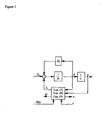
- This equation, together with (7), (8) and (9), are implemented in the electronic part of an SSG shown in Figure 3 .
- the state variables of the SSG are i (which are actual currents), ⁇ and ⁇ (which are a virtual angle and a virtual angular speed).
- the control inputs of the SSG are T m and M f i f .
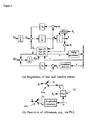
- a controller that generates the signals T m and M f i f such that system stability is maintained and the desired values of real and reactive power are followed. The significance of Q will be discussed in the next section.
- D p is defined as ⁇ ⁇ ⁇ ⁇ ⁇ T .
- the mechanical torque T m can be obtained from a set point of real power P set after dividing by the nominal mechanical speed ⁇ ⁇ a p . This completes the feedback loop for real power; see the upper part of Figure 4(a) . Because of the built-in frequency drooping mechanism, an SSG automatically shares the load with other inverters of the same type connected on the same bus. The power regulation loop is very simple because no mechanical devices arc involved and no measurements are needed for real power regulation (all variables are available internally).
- the time constant ⁇ f can be made much smaller than that of a physical synchronous generator.
- ⁇ f should be made small.
- J should be made small. This indicates that it is not necessary to have a large inertia for the virtual physical synchronous generator, although a larger inertia means that more energy can be stored. In other words, the energy storage function of an SSG can, and should, be decoupled from the inertia.
- the regulation of reactive power Q flowing out of the SSG can be realised similarly.
- the regulation mechanism for the reactive power can be realised as shown in the lower part of Figure 4(a) .
- the difference between the voltage reference v r e.g.
- the inner loop is the (amplitude) voltage loop and the outer loop is the reactive power loop.
- ⁇ a ⁇ ⁇ b + ⁇ b ⁇ ⁇ c + ⁇ c ⁇ ⁇ a - 3 4 ⁇ ⁇ m 2
- an SSG can be operated in the same way as a synchronous generator under normal working conditions.
- An important process related to an SSG or SG is the synchronisation procedure, prior to connection of the SSG/SG to another SSG/SG or to the public grid. This procedure involves bringing the terminal voltage v to be (almost) the same as the grid voltage v g on the other side of the circuit breaker 22, which means the same amplitude, the same frequency and the same phase angle. It is not an easy task to implement this for conventional SGs as this procedure involves much external equipment. For the SSG developed in this paper, this is relatively easy as the variables required are all available internally.
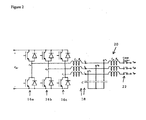
- a complete SSG consists of a power part shown in Figure 2 , and a complete electronic part shown in Figures 4(a) and (b) , which are interfaced with each other via ⁇ r , ⁇ y and v r . It can be seen that the nominal angular frequency ⁇ n and voltage (amplitude) v n are all set in the system via the frequency reference ⁇ r and voltage reference v r .
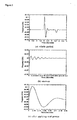
- D p and (D q ) should be chosen so that the full step change of real and reactive power should not cause noticeable change in the frequency and voltage.
- Table II PARAMETERS OF THE INVERTER-INFINITE BUS SYSTEM Parameters Values Parameters Values L s 0.15 mII L g 0.0534 mH R s 0.045 ⁇ R g 0.06 ⁇ C 22 ⁇ F Frequency 50 Hz R (parallel to C ) 1000 ⁇ Voltage (line-line) 17 Vrms Rated power 100 W Initial grid phase 0° Inertia J 0.01 Kgm 2 K 13580
Claims (15)
- Steuergerät für einen Umrichter, wobei das Steuergerät ein Modell eines Synchrongenerators realisiert, wobei dieser Umrichter auf der Basis von Parametern, die mittels dieses Modells berechnet werden, gesteuert wird, derart, dass er sich wie ein konventioneller Synchrongenerator verhält, umfassend:Variablen, die für die Winkellage und die Umlaufgeschwindigkeit eines virtuellen Generatorrotors stehen,eine Logik zur Berechnung eines virtuellen elektromagnetischen, auf den virtuellen Generatorrotor einwirkenden Drehmoments aus einem gemessenen Umrichter-Ausgangsstrom und einer Variablen, die für einen virtuellen Erregungsstrom steht,eine Logik zur Berechnung der Umlaufgeschwindigkeit des virtuellen, an den virtuellen Generatorrotor angelegten Rotors aus dem virtuellen elektromagnetischen Drehmoment und mindestens einer Variablen, die für ein virtuelles Antriebsmoment steht, und aus einem Parameter J, der für die virtuelle Trägheit des Rotors steht, wobei das Trägheitsmoment J als das Produkt der Zeitkonstante Tf einer Frequenz-Drooping-Schleife und eines Dämpfungsfaktors Dp, der sich als Frequenz-Drooping-Koeffizient verhält, gewählt wird undeine Logik zur Berechnung eines Steuersignals zur Steuerung des Umrichters aus den Variablen, die für die Winkellage und die Umlaufgeschwindigkeit des virtuellen Generatorrotors stehen, und aus der Variable, die für den Erregungsstrom steht, um einen Wechselstromausgang zu produzieren, der demjenigen des virtuellen Synchrongenerators entspricht, wobeidas Steuergerät ferner eine Logik umfasst, die eine erste Rückkopplungsschleife realisiert, in der Abweichungen der Umlaufgeschwindigkeit des virtuellen Generatorrotors von einer Referenzumlaufgeschwindigkeit erfasst und zur Anpassung des virtuellen Antriebsmoments verwendet werden, um dadurch die Winkelgeschwindigkeit des virtuellen Generatorrotors zu regeln und damit die Frequenz des Wechselstromausgangs von dem Umrichter und die reale Leistung, die von dem Umrichter geliefert wird, zu regeln.
- Steuergerät nach Anspruch 1, ferner eine Logik umfassend, die eine zweite Rückkopplungsschleife realisiert, in der Abweichungen einer gemessenen Umrichter-Ausgangsspannung von einem Referenzwert erfasst und bei der Anpassung des virtuellen Erregungsstroms verwendet werden, um somit die Umrichter-Ausgangsspannung zu regeln.
- Steuergerät nach Anspruch 2, bei dem die Abweichung einer Blindleistung von einem Referenzpegel erfasst und bei der Anpassung des virtuellen Erregungsstroms in der zweiten Rückkopplungsschleife verwendet wird, um somit die vom Umrichter gelieferte Blindleistung zu regeln.
- Steuergerät nach Anspruch 1, bei dem die erste Rückkopplungsschleife ein virtuelles Nennantriebsmoment als Eingang empfängt, welches zu einer Korrektur des virtuellen Antriebsmoments, das durch die Rückkopplungsschleife zur Bildung des virtuellen Antriebsmoments bereitgestellt wird, addiert wird, um das virtuelle Antriebsmoment zu bilden und das zum virtuellen elektromagnetischen Drehmoment addiert wird, um das virtuelle Gesamtdrehmoment zu bestimmen, das auf den virtuellen Generatorrotor wirkt.
- Steuergerät nach Anspruch 4, bei dem das virtuelle Gesamtdrehmoment, das auf den virtuellen Rotor wirkt, integriert ist und durch das virtuelle Rotormoment geteilt wird, um die Umlaufgeschwindigkeit des virtuellen Generatorrotors zu bestimmen.
- Steuergerät nach Anspruch 5, bei dem die Differenz zwischen der Umlaufgeschwindigkeit des virtuellen Generatorrotors und einer Referenzumlaufgeschwindigkeit, die der gewünschten Wechselstromausgangsfrequenz des Umrichters entspricht, mit einem Frequenz-Drooping-Koeffizienten multipliziert wird, um die Korrektur zum virtuellen Antriebsmoment zu bilden.
- Steuergerät nach Anspruch 4, bei dem das virtuelle Nennantriebsmoment durch Teilen eines Eingangs, der für die gewünschte reale Ausgangsleistung des Umrichters steht, durch einen Wert, der für die Winkelgeschwindigkeit eines Wechselstrom-Umrichterausgangs steht, bestimmt wird.
- Steuergerät nach Anspruch 1, bei dem das virtuelle elektromagnetische Drehmoment als das Produkt des gemessenen Umrichter-Ausgangsstroms, des virtuellen Erregungsstroms und einer Sinus- oder Cosinus-Funktion der Winkellage des virtuellen Generatorrotors berechnet wird.
- Steuergerät nach Anspruch 1, bei dem der Umrichter entsprechend gesteuert wird, um eine Wechselstromausgangsspannung bereitzustellen, die aufgrund des Modells des Synchrongenerators bestimmt wird.
- Steuergerät nach Anspruch 9, bei dem die von dem Umrichter bereitzustellende Wechselstromausgangsspannung als Produkt der Umlaufgeschwindigkeit des virtuellen Generatorrotors, des virtuellen Erregungsstroms und einer Sinus- oder Cosinus-Funktion der Winkellage des virtuellen Generatorrotors berechnet wird.
- Steuergerät nach Anspruch 10, bei dem das Steuersignal zur Steuerung des Umrichters pulsbreitenmoduliert ist, um den Umrichter zur Bereitstellung der berechneten Wechselstromausgangsspannung zu veranlassen.
- Steuergerät nach Anspruch 2, bei dem die Differenz zwischen der Blindleistung und deren Referenzpegel in der zweiten Rückkopplungsschleife zu einer Spannungs-Drooping-Variable, die für die Abweichung der gemessenen Umrichter-Ausgangsspannung von deren Referenzwert steht, addiert und zur Feststellung des virtuellen Erregungsstroms integriert wird.
- Verfahren zur Steuerung eines Umrichters, umfassend das Modellieren eines Synchrongenerators, um ein Modell zu erhalten, wobei dieser Umrichter auf der Basis von Parametern gesteuert wird, die mittels dieses Modells berechnet werden, derart, dass jener sich wie ein konventioneller Synchrongenerator verhält, wobei dieses Modell auf folgende Art und Weise modelliert wird:Durch das Darstellen der Winkellage und Umlaufgeschwindigkeit eines virtuellen Generatorrotors mittels nummerischen Variablen,durch das Messen des Ausgangsstroms des Umrichters,durch das Berechnen eines virtuellen elektromagnetischen, auf den virtuellen Generatorrotor wirkenden Drehmoments aus dem gemessenen Umrichter-Ausgangsstrom und einer Variablen, die für einen virtuellen Erregungsstrom steht,durch das Berechnen der Umlaufgeschwindigkeit des virtuellen, an den virtuellen Generatorrotor angelegten Rotors aus dem virtuellen elektromagnetischen Drehmoment und mindestens einer Variablen, die für ein virtuelles Antriebsmoment steht, und aus einem Parameter J, der für die virtuelle Trägheit des Rotors steht, wobei das Trägheitsmoment J als das Produkt der Zeitkonstante Tf einer Frequenz-Drooping-Schleife und eines Dämpfungsfaktors Dp, der sich als Frequenz-Drooping-Koeffizient verhält, gewählt wird unddurch das Berechnen eines Steuersignals aus den Variablen, die für die Winkellage und die Umlaufgeschwindigkeit des virtuellen Generatorrotors stehen, und aus der Variable, die für den Erregungsstrom steht, zur Steuerung des Umrichters zur Produktion eines Wechselstromausgangs, der demjenigen des virtuellen Synchrongenerators entspricht,durch das Realisieren einer ersten Rückkopplungsschleife, in der Abweichungen der Umlaufgeschwindigkeit des virtuellen Generatormotors von einer Referenzumlaufgeschwindigkeit erfasst und verwendet werden, um das virtuelle Antriebsmoment anzupassen, um somit die Umlaufgeschwindigkeit des virtuellen Generatorrotors und damit die Frequenz des Wechselstromausgangs des Umrichters und die Wirkleistung, die von dem Umrichter bereitgestellt wird, zu regeln.
- Verfahren nach Anspruch 13, ferner umfassend die Realisierung einer zweiten Rückkopplungsschleife, in der Abweichungen einer gemessenen Umrichter-Ausgangsspannung von einem Referenzwert erfasst und verwendet werden, um einen virtuellen Erregungsstrom anzupassen, um somit die Umrichter-Ausgangsspannung zu regeln.
- Verfahren nach Anspruch 13, bei dem die Abweichung einer Blindleistung von einem Referenzpegel erfasst und verwendet wird, um den virtuellen Erregungsstrom in der zweiten Rückkopplungsschleife anzupassen, um somit eine Blindleistung, die von dem Umrichter bereitgestellt wird, zu regeln.
Applications Claiming Priority (2)
| Application Number | Priority Date | Filing Date | Title |
|---|---|---|---|
| GBGB0820699.7A GB0820699D0 (en) | 2008-11-12 | 2008-11-12 | Static synchronous generators |
| PCT/GB2009/051460 WO2010055322A2 (en) | 2008-11-12 | 2009-10-29 | Static synchronous generators |
Publications (2)
| Publication Number | Publication Date |
|---|---|
| EP2377238A2 EP2377238A2 (de) | 2011-10-19 |
| EP2377238B1 true EP2377238B1 (de) | 2015-07-08 |
Family
ID=40139800
Family Applications (1)
| Application Number | Title | Priority Date | Filing Date |
|---|---|---|---|
| EP09756165.8A Active EP2377238B1 (de) | 2008-11-12 | 2009-10-29 | Statische synchrongeneratoren |
Country Status (6)
| Country | Link |
|---|---|
| US (1) | US8880236B2 (de) |
| EP (1) | EP2377238B1 (de) |
| CN (1) | CN102257720B (de) |
| ES (1) | ES2548786T3 (de) |
| GB (1) | GB0820699D0 (de) |
| WO (1) | WO2010055322A2 (de) |
Families Citing this family (52)
| Publication number | Priority date | Publication date | Assignee | Title |
|---|---|---|---|---|
| ES2613869T3 (es) | 2010-01-26 | 2017-05-26 | Vestas Wind Systems A/S | Método para la emulación de una máquina síncrona |
| CN102332718B (zh) * | 2010-06-23 | 2015-05-13 | 维斯塔斯风力系统有限公司 | 风力涡轮机及其操作方法、用于操作风力涡轮机的控制器 |
| ES2402465B1 (es) | 2011-02-28 | 2014-01-27 | Abengoa Solar New Technologies S.A. | Controlador de admitancia virtual basado en convertidores estáticos de potencia. |
| ES2402499B1 (es) | 2011-02-28 | 2013-11-26 | Abengoa Solar New Technologies S.A. | Controlador de la característica electromecánica virtual para convertidores estáticos de potencia. |
| ES2402467B1 (es) * | 2011-02-28 | 2014-01-27 | Abengoa Solar New Technologies S.A. | Controlador de potencia síncrona de un sistema de generación basado en convertidores estáticos de potencia. |
| CN102157937B (zh) * | 2011-04-08 | 2013-04-17 | 华北电力大学 | 一种基于逆系统的微网有功无功功率独立控制方法 |
| JP2013162623A (ja) * | 2012-02-03 | 2013-08-19 | Toshiba Corp | 給電システム |
| JP5953077B2 (ja) * | 2012-03-13 | 2016-07-13 | 東芝三菱電機産業システム株式会社 | インバータ試験装置 |
| JP6084863B2 (ja) * | 2013-02-28 | 2017-02-22 | 川崎重工業株式会社 | 系統連系する電力変換装置 |
| JP6386718B2 (ja) * | 2013-11-20 | 2018-09-05 | 川崎重工業株式会社 | 電力変換装置 |
| CN103972928B (zh) * | 2014-04-18 | 2016-05-25 | 国家电网公司 | 一种基于虚拟同步发电机的微网微源控制方法 |
| CN104734598B (zh) * | 2015-03-31 | 2017-08-15 | 西安交通大学 | 基于带通阻尼电压型变流器虚拟同步电机控制方法 |
| CN104953617B (zh) * | 2015-06-17 | 2017-08-11 | 清华大学 | 虚拟同步发电机带负载并网的控制方法及系统 |
| CN105186554B (zh) * | 2015-08-14 | 2017-09-29 | 许继集团有限公司 | 具有转动惯量和阻尼自趋优的虚拟同步发电机方法 |
| CN105281596B (zh) * | 2015-10-30 | 2018-01-23 | 清华大学 | 可变电容式静电电机的电子换相控制系统和控制方法 |
| CN105743130B (zh) * | 2016-03-22 | 2018-03-02 | 西安交通大学 | 提高虚拟同步发电机无功功率动态响应性能的方法 |
| US9970417B2 (en) | 2016-04-14 | 2018-05-15 | General Electric Company | Wind converter control for weak grid |
| CN105915140A (zh) * | 2016-04-22 | 2016-08-31 | 广东电网有限责任公司电力科学研究院 | 一种基于虚拟同步发电机的解耦控制方法及装置 |
| US10177574B2 (en) * | 2016-09-28 | 2019-01-08 | Nec Corporation | Dynamic frequency control scheme for microgrids using energy storage |
| CN106505617B (zh) * | 2016-11-18 | 2019-02-22 | 国网青海省电力公司 | 一种光伏微电网频率恢复方法及系统 |
| CN108242882B (zh) * | 2016-12-27 | 2022-02-15 | 顺涞新能源环保科技(深圳)有限公司 | 具有多组串联发电机构的高磁能交直流发电机 |
| JP6809753B2 (ja) * | 2016-12-28 | 2021-01-06 | 川崎重工業株式会社 | 複合発電システム |
| CN106655272B (zh) * | 2017-01-16 | 2018-12-04 | 湖南大学 | 抑制故障瞬时冲击电流型虚拟同步逆变器及其控制方法 |
| ES2874658T3 (es) | 2017-03-14 | 2021-11-05 | Abb Schweiz Ag | Procedimiento y sistema de control para controlar un convertidor de potencia |
| GB2563086B (en) | 2017-06-04 | 2020-09-16 | Zhong Qingchang | Cyber Synchronous Machine (in short, Cybersync Machine) |
| CN107196344B (zh) * | 2017-06-06 | 2020-05-05 | 湖南大学 | 基于spf-pll带本地负荷的自同步虚拟同步逆变器并网控制器及方法 |
| DE102017112936A1 (de) * | 2017-06-13 | 2018-12-13 | Wobben Properties Gmbh | Verfahren zum Einspeisen elektrischer Leistung mittels einer umrichtergeführten Erzeugungseinheit, insbesondere Windenergieanlage |
| CN107612043B (zh) * | 2017-09-18 | 2020-03-17 | 西安交通大学 | 一种基于相位前馈的虚拟同步发电机控制方法 |
| CN107565604B (zh) * | 2017-10-25 | 2020-05-19 | 合肥工业大学 | 多机并联虚拟同步发电机功率分配和参数自适应控制方法 |
| JP7052290B2 (ja) * | 2017-10-27 | 2022-04-12 | 東京電力ホールディングス株式会社 | 交直変換器制御装置 |
| GB2570151B (en) * | 2018-01-14 | 2020-07-15 | Zhong Qingchang | Reconfiguration of inertia, damping, and fault ride-through for a virtual synchronous machine |
| CN108363007B (zh) * | 2018-02-27 | 2024-03-29 | 华北电力科学研究院有限责任公司 | 一种光伏虚拟同步发电机性能测试装置及方法 |
| JP7025973B2 (ja) * | 2018-03-28 | 2022-02-25 | 株式会社日立製作所 | 分散電源の制御装置 |
| CN108462206B (zh) * | 2018-03-30 | 2020-01-10 | 华北电力科学研究院有限责任公司 | Vsg的虚拟惯量和阻尼系数的可选范围确定方法和装置 |
| CN108599264B (zh) * | 2018-05-10 | 2020-11-06 | 上海交通大学 | 一种基于虚拟同步发电机控制的频率电压无差调节方法 |
| GB2574645B (en) * | 2018-06-14 | 2020-07-15 | Zhong Qingchang | Passive virtual synchronous machine with bounded frequency and virtual flux |
| CN108923454B (zh) * | 2018-06-29 | 2022-09-02 | 中国电力科学研究院有限公司 | 一种直流侧电压下垂的负荷虚拟同步机的控制方法和装置 |
| CN109193810B (zh) * | 2018-09-06 | 2022-04-12 | 易事特集团股份有限公司 | 同步逆变器控制方法、装置及系统 |
| EP3647586A1 (de) * | 2018-10-29 | 2020-05-06 | GE Renewable Technologies | Verfahren zum starten einer hydraulikturbine |
| CN113474989A (zh) * | 2018-12-28 | 2021-10-01 | 维斯塔斯风力系统集团公司 | 带有虚拟同步发电机和直流链路控制的风力涡轮机 |
| CN111835028A (zh) * | 2019-04-15 | 2020-10-27 | 南京理工大学 | 基于虚拟同步发电机的微网逆变器控制方法 |
| CN110112769B (zh) * | 2019-04-16 | 2023-03-31 | 西安理工大学 | 虚拟同步机输出反馈自适应控制方法 |
| CN110739722B (zh) * | 2019-10-24 | 2021-04-27 | 合肥工业大学 | 级联型逆变器有功备用式变惯性虚拟同步控制方法 |
| CN110890765B (zh) * | 2019-11-19 | 2021-04-02 | 山东大学 | 双馈风机虚拟惯量调频的动态转速保护方法及系统 |
| CN110957741A (zh) * | 2019-12-30 | 2020-04-03 | 南京师范大学 | 一种需求侧背靠背变流器无功响应控制系统 |
| JP6735039B1 (ja) * | 2020-03-19 | 2020-08-05 | 富士電機株式会社 | 系統連系インバータ及び系統周波数の変動抑制方法 |
| JP2023533025A (ja) * | 2020-07-08 | 2023-08-01 | ラマト アット テル アビブ ユニバーシティ リミテッド | 電圧及び周波数制御が改善された仮想同期機 |
| CN112271737B (zh) * | 2020-07-30 | 2022-08-05 | 合肥工业大学 | 基于电感电流微分反馈的虚拟同步机强电网稳定控制方法 |
| CN112039131B (zh) * | 2020-08-07 | 2022-01-25 | 国电南瑞南京控制系统有限公司 | 一种基于虚拟同步机的双机并联系统功率分配方法及系统 |
| US11456645B2 (en) | 2020-12-10 | 2022-09-27 | General Electric Renovables Espana, S.L. | System and method for operating an asynchronous inverter-based resource as a virtual synchronous machine with storage |
| US11671039B2 (en) | 2020-12-10 | 2023-06-06 | General Electric Renovables Espana, S.L. | System and method for operating an asynchronous inverter-based resource as a virtual synchronous machine to provide grid-forming control thereof |
| CN114069697B (zh) * | 2021-11-16 | 2023-11-17 | 福州大学 | 一种基于虚拟同步发电机原理控制逆变器并网的方法 |
Family Cites Families (19)
| Publication number | Priority date | Publication date | Assignee | Title |
|---|---|---|---|---|
| JP2948887B2 (ja) * | 1990-09-07 | 1999-09-13 | 株式会社日立製作所 | 電動機の速度制御装置 |
| JPH10122119A (ja) * | 1996-10-22 | 1998-05-12 | Mitsubishi Electric Corp | 水車及びポンプ水車の調速制御装置並びにそれらの調速制御方法 |
| DE10011929B4 (de) * | 2000-03-11 | 2004-07-01 | Wobben, Aloys, Dipl.-Ing. | Synchrongenerator |
| CN1290252C (zh) * | 2000-11-09 | 2006-12-13 | 大金工业株式会社 | 同步电机控制方法及其装置 |
| JP2002204597A (ja) * | 2001-01-05 | 2002-07-19 | Honda Motor Co Ltd | インバータ制御式発電機 |
| DE10220122A1 (de) * | 2001-05-30 | 2002-12-19 | Continental Teves Ag & Co Ohg | Verfahren und Schaltungsanordnung zur sensorlosen, elektrischen Rotorlagemessung einer permanent erregten Synchronmaschine |
| US7680642B2 (en) * | 2005-01-12 | 2010-03-16 | The Japan Research Institute, Limited | Equivalent circuit for coil incorporated in circuit simulator, circuit simulator and method of preparation of same, and storage medium of circuit simulator program |
| CH697550B1 (de) * | 2005-03-30 | 2008-11-28 | Alstom Technology Ltd | Verfahren zur Steuerung eines Frequenzkonverters. |
| US7339344B2 (en) * | 2005-08-25 | 2008-03-04 | International Rectifier Corporation | Self tuning method and apparatus for permanent magnet sensorless control |
| US7592761B2 (en) * | 2005-09-29 | 2009-09-22 | Agile Systems Inc. | System and method for starting and operating a motor |
| US7256564B2 (en) * | 2005-09-29 | 2007-08-14 | Agile Systems Inc. | System and method for attenuating noise associated with a back electromotive force signal in a motor |
| US7279860B2 (en) * | 2005-09-29 | 2007-10-09 | Agile Systems Inc. | System and method for evaluating back electromotive force in a motor |
| US7288911B2 (en) * | 2005-09-29 | 2007-10-30 | Agile Systems Inc. | System and method for commutating a motor |
| US20070069677A1 (en) * | 2005-09-29 | 2007-03-29 | Mackay David K | System and method for applying energy to a motor |
| US7477034B2 (en) * | 2005-09-29 | 2009-01-13 | Agile Systems Inc. | System and method for commutating a motor using back electromotive force signals |
| JP2007159368A (ja) * | 2005-12-08 | 2007-06-21 | Toyota Motor Corp | モータ駆動システムの制御装置 |
| US7881814B2 (en) * | 2006-05-04 | 2011-02-01 | General Electric Company | Method and system for rapid modeling and verification of excitation systems for synchronous generators |
| JP4800839B2 (ja) * | 2006-05-23 | 2011-10-26 | 株式会社デンソー | 車両用界磁巻線型回転電機の励磁電流制御装置 |
| US7586286B2 (en) * | 2006-11-17 | 2009-09-08 | Continental Automotive Systems Us, Inc. | Method and apparatus for motor control |
-
2008
- 2008-11-12 GB GBGB0820699.7A patent/GB0820699D0/en active Pending
-
2009
- 2009-10-29 US US13/128,540 patent/US8880236B2/en active Active
- 2009-10-29 WO PCT/GB2009/051460 patent/WO2010055322A2/en active Application Filing
- 2009-10-29 CN CN200980151605.8A patent/CN102257720B/zh active Active
- 2009-10-29 ES ES09756165.8T patent/ES2548786T3/es active Active
- 2009-10-29 EP EP09756165.8A patent/EP2377238B1/de active Active
Also Published As
| Publication number | Publication date |
|---|---|
| CN102257720B (zh) | 2014-09-10 |
| ES2548786T3 (es) | 2015-10-20 |
| GB0820699D0 (en) | 2008-12-17 |
| US20110270463A1 (en) | 2011-11-03 |
| CN102257720A (zh) | 2011-11-23 |
| US8880236B2 (en) | 2014-11-04 |
| WO2010055322A2 (en) | 2010-05-20 |
| WO2010055322A3 (en) | 2010-07-22 |
| EP2377238A2 (de) | 2011-10-19 |
Similar Documents
| Publication | Publication Date | Title |
|---|---|---|
| EP2377238B1 (de) | Statische synchrongeneratoren | |
| Zhong et al. | Synchronverters: Inverters that mimic synchronous generators | |
| Zhong et al. | Static synchronous generators for distributed generation and renewable energy | |
| Boudjema et al. | Fuzzy sliding mode control of a doubly fed induction generator for wind energy conversion | |
| Flannery et al. | Evaluation of voltage sag ride-through of a doubly fed induction generator wind turbine with series grid side converter | |
| Benkahla et al. | Comparative study of robust control strategies for a DFIG-based wind turbine | |
| Choudhury et al. | Performance analysis of doublyfed induction generator for wind energy conversion system | |
| Bekakra et al. | Comparison study between SVM and PWM inverter in sliding mode control of active and reactive power control of a DFIG for variable speed wind energy | |
| Shukla et al. | DC grid/bus tied DFIG based wind energy system | |
| Boudjema et al. | Robust control of a doubly fed induction generator (DFIG) fed by a direct AC-AC converter | |
| Williamson et al. | A controller for single-phase parallel inverters in a variable-head pico-hydropower off-grid network | |
| Shukla et al. | Instantaneous direct voltage and frequency control in DC grid tied DFIG based wind energy system | |
| Luna et al. | Control of DFIG-WT under unbalanced grid voltage conditions | |
| WO2014107802A1 (en) | Grid-connected induction machine with controllable power factor | |
| Rodriguez et al. | Grid-following and grid-forming PV and wind turbines | |
| Attuati et al. | Proportional-resonant stator current controller applied to seig based systems | |
| Singh et al. | Power control in centralized distributed AC load for wind energy system | |
| Sheeja et al. | Neural network theory based voltage and frequency controller for standalone wind energy conversion system | |
| Bouzid et al. | Voltage and frequency control of wind-powered islanded microgrids based on induction generator and STATCOM | |
| Ion et al. | Single-phase operation of an autonomous three-phase induction generator using a VSI-DL control system | |
| Naeem et al. | A robust auto-synchronizer for synchronverter | |
| Paul et al. | Constant frequency-unified power quality conditioner | |
| Hosseini et al. | Modelling of PSPP control system by using vector control principle and VSI | |
| CN116111867B (zh) | 基于虚拟瞬时功率的构网型储能变换器预同步控制方法 | |
| Amorim et al. | Virtual Synchronous Generator with Harmonic Current Filtering Capability Based on Voltage Detection |
Legal Events
| Date | Code | Title | Description |
|---|---|---|---|
| PUAI | Public reference made under article 153(3) epc to a published international application that has entered the european phase |
Free format text: ORIGINAL CODE: 0009012 |
|
| 17P | Request for examination filed |
Effective date: 20110613 |
|
| AK | Designated contracting states |
Kind code of ref document: A2 Designated state(s): AT BE BG CH CY CZ DE DK EE ES FI FR GB GR HR HU IE IS IT LI LT LU LV MC MK MT NL NO PL PT RO SE SI SK SM TR |
|
| DAX | Request for extension of the european patent (deleted) | ||
| 17Q | First examination report despatched |
Effective date: 20131220 |
|
| GRAP | Despatch of communication of intention to grant a patent |
Free format text: ORIGINAL CODE: EPIDOSNIGR1 |
|
| INTG | Intention to grant announced |
Effective date: 20150206 |
|
| GRAS | Grant fee paid |
Free format text: ORIGINAL CODE: EPIDOSNIGR3 |
|
| GRAA | (expected) grant |
Free format text: ORIGINAL CODE: 0009210 |
|
| AK | Designated contracting states |
Kind code of ref document: B1 Designated state(s): AT BE BG CH CY CZ DE DK EE ES FI FR GB GR HR HU IE IS IT LI LT LU LV MC MK MT NL NO PL PT RO SE SI SK SM TR |
|
| REG | Reference to a national code |
Ref country code: GB Ref legal event code: FG4D |
|
| REG | Reference to a national code |
Ref country code: AT Ref legal event code: REF Ref document number: 736069 Country of ref document: AT Kind code of ref document: T Effective date: 20150715 Ref country code: CH Ref legal event code: EP |
|
| REG | Reference to a national code |
Ref country code: IE Ref legal event code: FG4D |
|
| REG | Reference to a national code |
Ref country code: DE Ref legal event code: R096 Ref document number: 602009032110 Country of ref document: DE |
|
| REG | Reference to a national code |
Ref country code: ES Ref legal event code: FG2A Ref document number: 2548786 Country of ref document: ES Kind code of ref document: T3 Effective date: 20151020 |
|
| REG | Reference to a national code |
Ref country code: FR Ref legal event code: PLFP Year of fee payment: 7 |
|
| REG | Reference to a national code |
Ref country code: AT Ref legal event code: MK05 Ref document number: 736069 Country of ref document: AT Kind code of ref document: T Effective date: 20150708 |
|
| REG | Reference to a national code |
Ref country code: NL Ref legal event code: MP Effective date: 20150708 |
|
| REG | Reference to a national code |
Ref country code: LT Ref legal event code: MG4D |
|
| PG25 | Lapsed in a contracting state [announced via postgrant information from national office to epo] |
Ref country code: LT Free format text: LAPSE BECAUSE OF FAILURE TO SUBMIT A TRANSLATION OF THE DESCRIPTION OR TO PAY THE FEE WITHIN THE PRESCRIBED TIME-LIMIT Effective date: 20150708 Ref country code: LV Free format text: LAPSE BECAUSE OF FAILURE TO SUBMIT A TRANSLATION OF THE DESCRIPTION OR TO PAY THE FEE WITHIN THE PRESCRIBED TIME-LIMIT Effective date: 20150708 Ref country code: GR Free format text: LAPSE BECAUSE OF FAILURE TO SUBMIT A TRANSLATION OF THE DESCRIPTION OR TO PAY THE FEE WITHIN THE PRESCRIBED TIME-LIMIT Effective date: 20151009 Ref country code: NO Free format text: LAPSE BECAUSE OF FAILURE TO SUBMIT A TRANSLATION OF THE DESCRIPTION OR TO PAY THE FEE WITHIN THE PRESCRIBED TIME-LIMIT Effective date: 20151008 Ref country code: FI Free format text: LAPSE BECAUSE OF FAILURE TO SUBMIT A TRANSLATION OF THE DESCRIPTION OR TO PAY THE FEE WITHIN THE PRESCRIBED TIME-LIMIT Effective date: 20150708 |
|
| PG25 | Lapsed in a contracting state [announced via postgrant information from national office to epo] |
Ref country code: SE Free format text: LAPSE BECAUSE OF FAILURE TO SUBMIT A TRANSLATION OF THE DESCRIPTION OR TO PAY THE FEE WITHIN THE PRESCRIBED TIME-LIMIT Effective date: 20150708 Ref country code: HR Free format text: LAPSE BECAUSE OF FAILURE TO SUBMIT A TRANSLATION OF THE DESCRIPTION OR TO PAY THE FEE WITHIN THE PRESCRIBED TIME-LIMIT Effective date: 20150708 Ref country code: AT Free format text: LAPSE BECAUSE OF FAILURE TO SUBMIT A TRANSLATION OF THE DESCRIPTION OR TO PAY THE FEE WITHIN THE PRESCRIBED TIME-LIMIT Effective date: 20150708 Ref country code: PT Free format text: LAPSE BECAUSE OF FAILURE TO SUBMIT A TRANSLATION OF THE DESCRIPTION OR TO PAY THE FEE WITHIN THE PRESCRIBED TIME-LIMIT Effective date: 20151109 Ref country code: PL Free format text: LAPSE BECAUSE OF FAILURE TO SUBMIT A TRANSLATION OF THE DESCRIPTION OR TO PAY THE FEE WITHIN THE PRESCRIBED TIME-LIMIT Effective date: 20150708 Ref country code: IS Free format text: LAPSE BECAUSE OF FAILURE TO SUBMIT A TRANSLATION OF THE DESCRIPTION OR TO PAY THE FEE WITHIN THE PRESCRIBED TIME-LIMIT Effective date: 20151108 |
|
| REG | Reference to a national code |
Ref country code: DE Ref legal event code: R097 Ref document number: 602009032110 Country of ref document: DE |
|
| PG25 | Lapsed in a contracting state [announced via postgrant information from national office to epo] |
Ref country code: EE Free format text: LAPSE BECAUSE OF FAILURE TO SUBMIT A TRANSLATION OF THE DESCRIPTION OR TO PAY THE FEE WITHIN THE PRESCRIBED TIME-LIMIT Effective date: 20150708 Ref country code: SK Free format text: LAPSE BECAUSE OF FAILURE TO SUBMIT A TRANSLATION OF THE DESCRIPTION OR TO PAY THE FEE WITHIN THE PRESCRIBED TIME-LIMIT Effective date: 20150708 Ref country code: DK Free format text: LAPSE BECAUSE OF FAILURE TO SUBMIT A TRANSLATION OF THE DESCRIPTION OR TO PAY THE FEE WITHIN THE PRESCRIBED TIME-LIMIT Effective date: 20150708 Ref country code: CZ Free format text: LAPSE BECAUSE OF FAILURE TO SUBMIT A TRANSLATION OF THE DESCRIPTION OR TO PAY THE FEE WITHIN THE PRESCRIBED TIME-LIMIT Effective date: 20150708 |
|
| PLBE | No opposition filed within time limit |
Free format text: ORIGINAL CODE: 0009261 |
|
| STAA | Information on the status of an ep patent application or granted ep patent |
Free format text: STATUS: NO OPPOSITION FILED WITHIN TIME LIMIT |
|
| PG25 | Lapsed in a contracting state [announced via postgrant information from national office to epo] |
Ref country code: LU Free format text: LAPSE BECAUSE OF FAILURE TO SUBMIT A TRANSLATION OF THE DESCRIPTION OR TO PAY THE FEE WITHIN THE PRESCRIBED TIME-LIMIT Effective date: 20151029 Ref country code: RO Free format text: LAPSE BECAUSE OF FAILURE TO SUBMIT A TRANSLATION OF THE DESCRIPTION OR TO PAY THE FEE WITHIN THE PRESCRIBED TIME-LIMIT Effective date: 20150708 |
|
| REG | Reference to a national code |
Ref country code: CH Ref legal event code: PL |
|
| 26N | No opposition filed |
Effective date: 20160411 |
|
| PG25 | Lapsed in a contracting state [announced via postgrant information from national office to epo] |
Ref country code: MC Free format text: LAPSE BECAUSE OF FAILURE TO SUBMIT A TRANSLATION OF THE DESCRIPTION OR TO PAY THE FEE WITHIN THE PRESCRIBED TIME-LIMIT Effective date: 20150708 |
|
| REG | Reference to a national code |
Ref country code: IE Ref legal event code: MM4A |
|
| PG25 | Lapsed in a contracting state [announced via postgrant information from national office to epo] |
Ref country code: LI Free format text: LAPSE BECAUSE OF NON-PAYMENT OF DUE FEES Effective date: 20151031 Ref country code: CH Free format text: LAPSE BECAUSE OF NON-PAYMENT OF DUE FEES Effective date: 20151031 |
|
| PG25 | Lapsed in a contracting state [announced via postgrant information from national office to epo] |
Ref country code: SI Free format text: LAPSE BECAUSE OF FAILURE TO SUBMIT A TRANSLATION OF THE DESCRIPTION OR TO PAY THE FEE WITHIN THE PRESCRIBED TIME-LIMIT Effective date: 20150708 |
|
| REG | Reference to a national code |
Ref country code: FR Ref legal event code: PLFP Year of fee payment: 8 |
|
| PG25 | Lapsed in a contracting state [announced via postgrant information from national office to epo] |
Ref country code: IE Free format text: LAPSE BECAUSE OF NON-PAYMENT OF DUE FEES Effective date: 20151029 |
|
| PG25 | Lapsed in a contracting state [announced via postgrant information from national office to epo] |
Ref country code: BE Free format text: LAPSE BECAUSE OF FAILURE TO SUBMIT A TRANSLATION OF THE DESCRIPTION OR TO PAY THE FEE WITHIN THE PRESCRIBED TIME-LIMIT Effective date: 20150708 |
|
| PG25 | Lapsed in a contracting state [announced via postgrant information from national office to epo] |
Ref country code: HU Free format text: LAPSE BECAUSE OF FAILURE TO SUBMIT A TRANSLATION OF THE DESCRIPTION OR TO PAY THE FEE WITHIN THE PRESCRIBED TIME-LIMIT; INVALID AB INITIO Effective date: 20091029 Ref country code: BG Free format text: LAPSE BECAUSE OF FAILURE TO SUBMIT A TRANSLATION OF THE DESCRIPTION OR TO PAY THE FEE WITHIN THE PRESCRIBED TIME-LIMIT Effective date: 20150708 Ref country code: SM Free format text: LAPSE BECAUSE OF FAILURE TO SUBMIT A TRANSLATION OF THE DESCRIPTION OR TO PAY THE FEE WITHIN THE PRESCRIBED TIME-LIMIT Effective date: 20150708 |
|
| PG25 | Lapsed in a contracting state [announced via postgrant information from national office to epo] |
Ref country code: CY Free format text: LAPSE BECAUSE OF FAILURE TO SUBMIT A TRANSLATION OF THE DESCRIPTION OR TO PAY THE FEE WITHIN THE PRESCRIBED TIME-LIMIT Effective date: 20150708 Ref country code: NL Free format text: LAPSE BECAUSE OF FAILURE TO SUBMIT A TRANSLATION OF THE DESCRIPTION OR TO PAY THE FEE WITHIN THE PRESCRIBED TIME-LIMIT Effective date: 20150708 |
|
| PG25 | Lapsed in a contracting state [announced via postgrant information from national office to epo] |
Ref country code: TR Free format text: LAPSE BECAUSE OF FAILURE TO SUBMIT A TRANSLATION OF THE DESCRIPTION OR TO PAY THE FEE WITHIN THE PRESCRIBED TIME-LIMIT Effective date: 20150708 Ref country code: MT Free format text: LAPSE BECAUSE OF FAILURE TO SUBMIT A TRANSLATION OF THE DESCRIPTION OR TO PAY THE FEE WITHIN THE PRESCRIBED TIME-LIMIT Effective date: 20150708 |
|
| REG | Reference to a national code |
Ref country code: FR Ref legal event code: PLFP Year of fee payment: 9 |
|
| PG25 | Lapsed in a contracting state [announced via postgrant information from national office to epo] |
Ref country code: MK Free format text: LAPSE BECAUSE OF FAILURE TO SUBMIT A TRANSLATION OF THE DESCRIPTION OR TO PAY THE FEE WITHIN THE PRESCRIBED TIME-LIMIT Effective date: 20150708 |
|
| REG | Reference to a national code |
Ref country code: FR Ref legal event code: PLFP Year of fee payment: 10 |
|
| P01 | Opt-out of the competence of the unified patent court (upc) registered |
Effective date: 20230529 |
|
| PGFP | Annual fee paid to national office [announced via postgrant information from national office to epo] |
Ref country code: GB Payment date: 20231020 Year of fee payment: 15 |
|
| PGFP | Annual fee paid to national office [announced via postgrant information from national office to epo] |
Ref country code: ES Payment date: 20231222 Year of fee payment: 15 |
|
| PGFP | Annual fee paid to national office [announced via postgrant information from national office to epo] |
Ref country code: IT Payment date: 20231026 Year of fee payment: 15 Ref country code: FR Payment date: 20231024 Year of fee payment: 15 Ref country code: DE Payment date: 20231020 Year of fee payment: 15 |