WO2010055322A2 - Static synchronous generators - Google Patents
Static synchronous generators Download PDFInfo
- Publication number
- WO2010055322A2 WO2010055322A2 PCT/GB2009/051460 GB2009051460W WO2010055322A2 WO 2010055322 A2 WO2010055322 A2 WO 2010055322A2 GB 2009051460 W GB2009051460 W GB 2009051460W WO 2010055322 A2 WO2010055322 A2 WO 2010055322A2
- Authority
- WO
- WIPO (PCT)
- Prior art keywords
- virtual
- inverter
- rotor
- rotational speed
- control device
- Prior art date
Links
Classifications
-
- H—ELECTRICITY
- H02—GENERATION; CONVERSION OR DISTRIBUTION OF ELECTRIC POWER
- H02P—CONTROL OR REGULATION OF ELECTRIC MOTORS, ELECTRIC GENERATORS OR DYNAMO-ELECTRIC CONVERTERS; CONTROLLING TRANSFORMERS, REACTORS OR CHOKE COILS
- H02P9/00—Arrangements for controlling electric generators for the purpose of obtaining a desired output
- H02P9/02—Details
-
- H—ELECTRICITY
- H02—GENERATION; CONVERSION OR DISTRIBUTION OF ELECTRIC POWER
- H02P—CONTROL OR REGULATION OF ELECTRIC MOTORS, ELECTRIC GENERATORS OR DYNAMO-ELECTRIC CONVERTERS; CONTROLLING TRANSFORMERS, REACTORS OR CHOKE COILS
- H02P23/00—Arrangements or methods for the control of AC motors characterised by a control method other than vector control
- H02P23/12—Observer control, e.g. using Luenberger observers or Kalman filters
-
- H—ELECTRICITY
- H02—GENERATION; CONVERSION OR DISTRIBUTION OF ELECTRIC POWER
- H02P—CONTROL OR REGULATION OF ELECTRIC MOTORS, ELECTRIC GENERATORS OR DYNAMO-ELECTRIC CONVERTERS; CONTROLLING TRANSFORMERS, REACTORS OR CHOKE COILS
- H02P23/00—Arrangements or methods for the control of AC motors characterised by a control method other than vector control
- H02P23/14—Estimation or adaptation of motor parameters, e.g. rotor time constant, flux, speed, current or voltage
-
- H—ELECTRICITY
- H02—GENERATION; CONVERSION OR DISTRIBUTION OF ELECTRIC POWER
- H02P—CONTROL OR REGULATION OF ELECTRIC MOTORS, ELECTRIC GENERATORS OR DYNAMO-ELECTRIC CONVERTERS; CONTROLLING TRANSFORMERS, REACTORS OR CHOKE COILS
- H02P9/00—Arrangements for controlling electric generators for the purpose of obtaining a desired output
- H02P9/14—Arrangements for controlling electric generators for the purpose of obtaining a desired output by variation of field
- H02P9/26—Arrangements for controlling electric generators for the purpose of obtaining a desired output by variation of field using discharge tubes or semiconductor devices
- H02P9/30—Arrangements for controlling electric generators for the purpose of obtaining a desired output by variation of field using discharge tubes or semiconductor devices using semiconductor devices
-
- H—ELECTRICITY
- H02—GENERATION; CONVERSION OR DISTRIBUTION OF ELECTRIC POWER
- H02P—CONTROL OR REGULATION OF ELECTRIC MOTORS, ELECTRIC GENERATORS OR DYNAMO-ELECTRIC CONVERTERS; CONTROLLING TRANSFORMERS, REACTORS OR CHOKE COILS
- H02P2101/00—Special adaptation of control arrangements for generators
- H02P2101/15—Special adaptation of control arrangements for generators for wind-driven turbines
Definitions
- the present invention is concerned with a control device for an inverter associated with an electrical power supply. Specifically, the control device causes the power supply and inverter together to mimic in some respects the behaviour of a synchronous electrical generator.
- Wind turbines for example, are most effective if free to generate at variable frequency and so they require conversion from variable frequency AC to DC to AC; small gas-turbines with direct drive generators operate at high frequency and require AC to DC to AC conversion; photo-voltaic arrays require DC-AC conversion. More and more inverters will be connected to the grid and will probably dominate the power generation eventually. In all of these cases the same basic inverters arc used and need to he controlled to provide high-quality supply waveforms to consumers.
- the current paradigm in the control ofwind or solar power generators is to extract the maximum power from the power source and inject it all into the power grid. This is a good policy as long as such power sources constitute a negligible part of the grid power capacity, and power fluctuation of the renewable power generators can be compensated by the controllers associated with the grid's large conventional generators. Some of these generators will also take care of overall system stability and fault ride-through. When renewable power generators (especially the solar ones) provide the majority of the grid power, such "irresponsible" behaviour (on their part) will become untenable. Thus, the need will arise to operate them in the same way as conventional power generators function today.
- SSG static synchronous generator
- IEEE Institute of Electrical and Electronic Engineers
- a control device for an inverter comprising variables representing the angular position and rotational speed of a virtual generator rotor, logic for calculating a virtual electromagnetic torque acting on the virtual generator rotor from measured inverter output current and from a variable representing a virtual excitation current, logic for calculating the rotational speed of the virtual rotor from the virtual electromagnetic torque and from at least one variable representing a virtual drive torque applied to the virtual generator rotor, and from a parameter representing the rotor's virtual inertia, and logic for calculating, from the variables representing angular position and rotational speed of the virtual generator rotor and from the variable representing the excitation current, a control signal for controlling the inverter to produce an AC output which corresponds to that of the virtual synchronous generator, the control device further comprising logic which implements a first feedback loop in which deviation of the rotational speed of the virtual generator rotor from a reference
- a method of controlling an inverter comprising modelling of a synchronous generator by representing the angular position and rotational speed of a virtual generator rotor using numerical variables, measuring the inverter's output current, calculating a virtual electromagnetic torque acting on the virtual generator rotor from measured inverter output current and from a variable representing a virtual excitation current, calculating the rotational speed of the virtual rotor from the virtual electromagnetic torque and from at least one variable representing a virtual drive torque applied to the virtual generator rotor, and from a parameter representing the rotor's virtual inertia, and calculating, from the variables representing angular position and rotational speed of the virtual generator rotor and from the variable representing the excitation current, a control signal for controlling the inverter to produce an AC output which corresponds to that of the virtual synchronous generator, implementing a first feedback loop in which deviation of the rotational speed of the virtual generator rotor from a reference rotational speed is detected and used to adjust the
- Figure 2 is a circuit diagram of an inverter for use in implementing the present invention
- Figure 3 is a block diagram representation of a virtual synchronous generator, without control logic
- Figure 4 corresponds to Figure 3 but includes control logic
- Figures 5a to c arc graphs of frequency variation over time in a simulation of an SSG according to the present invention
- Figures 6 a and b arc graphs of real and reactive power respectively in the simulation
- Figure 7a shows variation of the amplitude of the terminal voltage of the SSG during simulation
- Figure 7b shows, over a much briefer period of time, the sinusoidal variation of the three AC phases of the output from the SSG in a steady state
- Figures 8a to c are graphs of (a) frequency, (b) real and reactive power and (c) terminal voltage amplitude, all over time and all obtained in a second simulation of the SSG, this time in island mode
- Section I a dynamic model of a synchronous generator is established under no assumptions on the signals. Although the model of an SG has been well described in the literature, the way the model is described here is somewhat fresh. Then, how to implement an inverter to mimic a synchronous generator is described in Section II and a system embodying the present invention for control of an SSG, incorporating frequency and voltage drooping mechanisms for load sharing, is described in Section III, followed by simulation results given in Section IV.
- the present embodiment of the invention is based on a mathematical model of a synchronous generator which is considered to be a dynamic system without any assumptions on the signals.
- a generator arrangement 10 seen in Figure 1 which is a round rotor machine (without damping windings), with p pairs of poles per phase and no saturation effects in the iron core.
- stator windings 12a-c arc distributed in slots around the periphery of a uniform air gap.
- the stator windings can be regarded as concentrated coils having self-inductance L and mutual inductance -M (M > 0 with a typical value
- a field (or rotor) winding 14 can be regarded as a concentrated coil having self-inductance L ⁇ .
- the mutual inductance between the field winding 14 and each of the three stator coils 12a-c varies with respect to the rotor angle ⁇ as follows:
- i ⁇ i b and i c are the stator phase currents and i ⁇ is the rotor excitation current, i.e. the current through the rotor winding 14.
- stator flux linkages can be rewritten as where L 1 - L + M, and the field flux linkage can be rewritten where ' denotes the conventional inner product.
- Mf (! cos ⁇ ) j s constant if the three phase currents are sinusoidal and balanced. Assume that the resistance of the stator windings is R 8 , then the phase terminal
- T e the electromagnetic torque on the rotor due to its interaction with the stators
- D p the damping factor
- stator flux linkages (1) Assume where i N is the current flowing through the neutral line. Then the formula for the stator flux linkages (1) becomes and the phase terminal voltages (3) become
- a simple DC/AC converter used to convert the DC power supply VDC obtained from renewable/distributed energy sources into three-phase AC (v ⁇ ,v b ,v c ) is shown in Figure 2. It consists of three phase legs 16a-c and a three-phase LC filter 18 which is used to suppress the switching noise. If the inverter is to be connected to the grid then a three-phase coupling inductor 20 and a circuit breaker 22 are needed to interface with the grid.
- the inverter is to be connected to the grid then a three-phase coupling inductor 20 and a circuit breaker 22 are needed to interface with the grid.
- filtering capacitors C should be chosen such that the resonant frequency is
- ⁇ n is the nominal angular frequency of the voltage and ⁇ s is the angular switching frequency used to turn on/off inverter switches in the phase legs 16a-c (insulated gate bipolar transistors 22 are shown in the figure but other types of switch could be substituted).
- An SSG can be implemented according to the mathematical model developed in the previous section. As explained in detail later in this section, an SSG consists of a power part, ie., the inverter shown in Figure 2, and an electronic part shown in Figure 3. These two parts are interfaced via the signals e and i (and v and v g to be used for regulating purposes).
- Equation (6) can be written as where the input is the mechanical torque T m , while the electromagnetic torque T e depends on i and ⁇ , according to (7).
- This equation, together with (T), (8) and (9), are implemented in the electronic part of an SSG shown in Figure 3.
- the state variables of the SSG are i (which are actual currents), ⁇ and ⁇ (which are a virtual angle and a virtual angular speed).
- the control inputs of the SSG are T n , and Mfif.
- T n The control inputs of the SSG.
- Mfif the control inputs of the SSG.
- the terminal voltages given in (3) can be obtained from the (local load) terminals v a , v / , and v c of the inverter shown in Figure 2.
- the inductance L x and resistance R s of the inductor can be chosen to represent the stator impedance of a synchronous generator.
- the switches in the inverter are operated so that the average values of e a , ⁇ JJ, and e c over a switching period should be equal to e given in (8) and, hence no special pulse-width-modulation (PWM) techniques are necessary.
- PWM pulse-width-modulation
- Also shown in Figure 2 is a three-phase interfacing inductor L ⁇ /R g and a circuit breaker to facilitate synchronisation/connection with the grid.
- Tlic terms "real" and “reactive” power arc very well known in relation to AC power transmissioa
- the power flow resulting in net transfer of energy, over a complete AC cycle, is the real power.
- the power flow due to energy which is stored and returned to the source over a cycle (by virtue of capacitance, inductance or equivalent) is the reactive power.
- T mn is the nominal mechanical torque
- the mechanical torque T 1n can be obtained from a set point
- the regulation mechanism of the real power (torque) shown in the upper part of Figure 4(a) has a cascaded control structure, of which the inner loop is the frequency loop and the outer loop is the real power (torque) loop.
- the time constant of the frequency loop is
- the time constant Tt can be made much smaller than that of a physical synchronous generator.
- T( should be made small.
- J should be made small. This indicates that it is not necessary to have a large inertia for the virtual physical synchronous generator, although a larger inertia means that more energy can be stored. In other words, the energy storage tunction of an SSG can, and should, be decoupled from the inertia.
- the regulation of reactive power Q flowing out of the SSG can be realised similarly.
- the voltage drooping coefficient D p as the ratio of the required change of reactive power AQ to the change of voltage ⁇ v, i.e. where Q n is the nominal reactive power, which can be chosen as the nominal power, and v n is the nominal amplitude of terminal voltage v.
- the regulation mechanism for the reactive power can be realised as shown in the lower part of Figure 4(a).
- the difference between the voltage reference v o e.g.
- the amplitude v ⁇ of the nominal voltage, and the amplitude v m of the actual terminal voltage v is amplified by the voltage drooping coefficient D q before adding to the difference between the set point Q se , and the current reactive power Q, which is calculated according to (9).
- the resulting signal is then fed into an integrator with a
- the inner loop is the (amplitude) voltage loop and the outer loop is the reactive power loop.
- the time constant of the voltage loop is
- the amplitude v n , of the terminal voltage v can be obtained as follows. Assume
- a low-pass filter is needed to filter out the ripples at the doubled frequency as the terminal voltages may be unbalanced. This also applies to T e and Q.
- an SSG can be operated in the same way as a synchronous generator under normal working conditions.
- An important process related to an SSG or SG is the synchronisation procedure, prior to connection of the SSG/SG to another SSG/SG or to the public grid. This procedure involves bringing the terminal voltage v to be (almost) the same as the grid voltage v g on the other side of the circuit breaker 22, which means the same amplitude, the same frequency and the same phase angle. It is not an easy task to implement this for conventional SGs as this procedure involves much external equipment. For the SSG developed m this paper, this is relatively easy as the variables required are all available internally.
- a change of operation mode from island mode (in which the SSG operates without connection to a power grid) to grid-connected mode or vice verse can be implemented via a controlled multi-pole-double-throw (MPDT) switch 30a, b, Figure 4, with one throw for island mode (labelled as i) and the other for grid-connected mode (labelled as g), to change the frequency/voltage references.
- MPDT multi-pole-double-throw
- the status of the MPDT switch 30a, b is determined by the presence of the grid voltage and the status of a mode switch which sets the operation mode of the SSG. See Table 1 for the logic of operation.
- the default position of the mode switch is at "grid- connected" and it is turned to "island" when there is a fault.
- the frequency/voltage references arc set as the corresponding values of the grid voltage v g and the integrator that produces phase ⁇ , the electrical angle between the rotor field and the phasc-a field, is reset according to the grid phase when the circuit breaker is not turned on.
- the SSG can provide a green (go-ahead) signal for the operator to turn on the circuit breaker (it can be set to turn on automatically).
- the circuit breaker is allowed to be turned on in two cases: (1) when the MPDT switch i.g. is set at Throw g, i.e., when the grid voltage is present and the mode switch is turned at grid-connected mode; (2) when the grid voltage is not present and the mode switch is turned at island mode, which allows parallel operation of multiple inverters (to be discussed in more detail later).
- an SSG works in island mode and the real power and reactive power delivered by the SSG are determined by the load. If there is more than one SSG to be connected in parallel, then the first one that is put into operation works with the mode switch set at "island" to establish the system frequency and voltage. Note that in this case the circuit breaker can be turned on straightaway, according to the logic of operation set in Table 1, so that the voltage is present on the other side of the circuit breaker, which allows other SSGs to synchronise with it and to join the system under the grid -connected mode. In this case, P set and Q set should be set at 0 as the power delivered is determined by the local load.
- a complete SSG consists of a power part shown in Figure 2, and a complete electronic part shown in Figures 4(a) and (b), which are
- a resetting mechanism is added to the integrator generating ⁇ to prevent numerical overflow under normal working condition and to obtain the same phase as the grid voltage during synchronisation.
- the phase of the SSG can be reset as 0 when the grid voltage crosses U, which is impossible for a physical synchronous generator.
- Another important mechanism is to add a constant phase shift ⁇ c to the phase ⁇ so that the delay in the PWM switching process and the phase shift of the LC filter can be compensated, which brings the phase difference between v and v g to be minimal during synchronisation.
- the electronic part of an SSG can be implemented in a microcontroller (this is normally the case) and, hence, it is possible to use different values of D ⁇ (D q ) and J (K) when the SSG works in different modes.
- D ⁇ and J Some guidelines on choosing D ⁇ and J are: (I) D ⁇ should be chosen to satisfy the frequency regulation requirement; (2) J should be chosen to achieve the desired frequency-loop time constant T t ;
- D 9 should be chosen to satisfy the voltage regulation requirement; (2) K should be chosen to achieve the desired voltage-loop time constant ⁇ v .
- D n and (D q ) should be chosen so that the full step change of real and reactive power should not cause noticeable change in the frequency and voltage.
- the simulation was carried out in MATLAB® 7.4 with SimulinkTM.
- the solver used in the simulations is ode23tb with a relative tolerance 10 -3 and a maximum step size of 10 -4 second.
- the inverter is connected to the grid via a circuit breaker and a step-up transformer.
- the response of the SSG frequency is shown in Figure 5.
- the frequency of the SSG increased and then returned to the grid frequency 50Hz after about 20 cycles.
- the frequency of the SSG decreased slightly and then returned to the grid frequency quickly.
- the output power of the SSG is shown in Figure 6. During the synchronisation period, there were some oscillations in the power (which is inside the controller as the hreaker is not yet turned on and hence it does not cause any problem).
Landscapes
- Engineering & Computer Science (AREA)
- Power Engineering (AREA)
- Control Of Eletrric Generators (AREA)
Abstract
The invention is concerned with a device and a method for controlling an inverter associated with a power source, which typically will be a distributed power source. The role of an inverter is to modulate the electrical power output, e.g. to provide a three phase AC electrical output at suitable voltage, where the output is to be supplied to a conventional power distribution, grid. The invention involves modelling the behaviour of a synchronous electrical generator. Variables represent the angular position and rotational speed of the virtual rotor (14) of this virtual synchronous generator. The torque electromagnetically exerted on the rotor is calculated from a measured inverter output current, and from a variable representing excitation current in the rotor. Allowing for this and for a notional drive torque applied to the virtual rotor (which in the physical analogue would be supplied by some prime mover such as an engine), as well as for the virtual inertia of the rotor, the angular speed of the virtual rotor is calculated, Using the angular position and rotational speed of the virtual rotor, and allowing for the aforementioned excitation current, it is possible to obtain the cmf induced in stators of the virtual generator. On this basis a control signal is generated which causes the inverter to produce an AC output corresponding to that which would be provided by the virtual synchronous generator. A synchronous generator must be regulated, as too must the virtual synchronous generator of the present invention. To this end, the invention provides a feedback loop in which deviation of the rotational speed of the virtual generator rotor from a reference angular speed is detected and is used to adjust the virtual drive torque, thereby to regulate the rotational speed of the rotor and hence the frequency of the AC output and the real power supplied by it.
Description
STATIC SYNCHRONOUS GENERATORS
The present invention is concerned with a control device for an inverter associated with an electrical power supply. Specifically, the control device causes the power supply and inverter together to mimic in some respects the behaviour of a synchronous electrical generator.
For economic, technical and environmental reasons, more and more distributed energy sources, such as combined heat and power (CHP) plants, and renewable energy sources, such as wind power, solar power, wave and tidal power etc, will play an important role in the future electricity supply. The EU has set a 22% target for the share of renewable energy sources and an 18% target for the share of CHP in electricity generation by 2010. The electrical power system is currently undergoing a dramatic change from centralised generation to distributed generation. Most of these distributed/renewable energy generators produce variable frequency AC sources, high frequency AC, or DC sources, and consequently require DC-AC converters to interface with the public grid. The term "inverter" will be used herein to refer to any device for converting DC to a controlled AC output. Wind turbines, for example, are most effective if free to generate at variable frequency and so they require conversion from variable frequency AC to DC to AC; small gas-turbines with direct drive generators operate at high frequency and require AC to DC to AC conversion; photo-voltaic arrays require DC-AC conversion. More and more inverters will be connected to the grid and will probably dominate the power generation eventually. In all of
these cases the same basic inverters arc used and need to he controlled to provide high-quality supply waveforms to consumers.
The current paradigm in the control ofwind or solar power generators is to extract the maximum power from the power source and inject it all into the power grid. This is a good policy as long as such power sources constitute a negligible part of the grid power capacity, and power fluctuation of the renewable power generators can be compensated by the controllers associated with the grid's large conventional generators. Some of these generators will also take care of overall system stability and fault ride-through. When renewable power generators (especially the solar ones) provide the majority of the grid power, such "irresponsible" behaviour (on their part) will become untenable. Thus, the need will arise to operate them in the same way as conventional power generators function today. This requires first of all large and high efficiency energy storage units, so that the random fluctuations of the prime power source can be filtered out, but it also requires appropriate control of the outputs of the distributed energy sources. There are two options. One is to re-design the whule power system and to change the way it is operated. The other is to find a way for the inverters to be integrated into the existing system and behave in the same way as large synchronous generators (SG), which arc the main generators in power plants of today. Apparently, the first option is not economically viable.
It has been proposed that the inverters associated with distributed energy sources should be operated to mimic the behaviour of a synchronous generator (SG). The
term "static synchronous generator ( SSG)" has been defined by the Institute of Electrical and Electronic Engineers (IEEE) to represent a static, self-commutated switching power converter supplied from an appropriate electric energy source and o perated t o p roduce a s et o f a djustab Ie m ulli -phase o utput v oltagcs, w hich may be coupled to an AC power system for the purpose of exchanging independently controllable real and reactive power. This was originally d efined for one of the shunt-connected controllers in FACTS (flexible AC transmission system). This term is borrowed here to represent inverters which behave like synchronous generators. An SSG has the characteristics of an SG but without rotaling parts (hence static). In this way, distributed energy sources can be made to operate on principles well understood in connection with conventional synchronous generators.
A paper entitled "Virtual Synchronous Machine" given at the 9th International Conference on Electrical Power Quality and Utilisation of 9-1 1 October 2007 by H.P. Beck and R. Hesse describes the basic concept of a virtual synchronous generator, as does the paper "Virtual Synchronous Generators" published in 2008 IEEE Power and Energy Society General - Conversion and Delivery of Electrical Energy in the 21st Century , pages 1-3, 2008 and written by J. Driesen and J. Visscher. Neither paper describes the practical details of & system required to control a static synchronous generator and this aspect remains problematic.
In accordance witli a first aspect of the present invention there is a control device for an inverter, the control device implementing a model of a synchronous generator comprising variables representing the angular position and rotational speed of a virtual generator rotor, logic for calculating a virtual electromagnetic torque acting on the virtual generator rotor from measured inverter output current and from a variable representing a virtual excitation current, logic for calculating the rotational speed of the virtual rotor from the virtual electromagnetic torque and from at least one variable representing a virtual drive torque applied to the virtual generator rotor, and from a parameter representing the rotor's virtual inertia, and logic for calculating, from the variables representing angular position and rotational speed of the virtual generator rotor and from the variable representing the excitation current, a control signal for controlling the inverter to produce an AC output which corresponds to that of the virtual synchronous generator, the control device further comprising logic which implements a first feedback loop in which deviation of the rotational speed of the virtual generator rotor from a reference rotational speed is detected and used to adjust the virtual drive torque, thereby to regulate the angular speed of the virtual generator rotor, and hence to regulate frequency of the ΛC output from the inverter and the real power supplied by the inverter.
In accordance with a second aspect of the present invention, there is a method of controlling an inverter, comprising modelling of a synchronous generator by representing the angular position and rotational speed of a virtual generator rotor using numerical variables, measuring the inverter's output current, calculating a virtual electromagnetic torque acting on the virtual generator rotor from measured inverter output current and from a variable representing a virtual excitation current, calculating the rotational speed of the virtual rotor from the virtual electromagnetic torque and from at least one variable representing a virtual drive torque applied to the virtual generator rotor, and from a parameter representing the rotor's virtual inertia, and calculating, from the variables representing angular position and rotational speed of the virtual generator rotor and from the variable representing the excitation current, a control signal for controlling the inverter to produce an AC output which corresponds to that of the virtual synchronous generator, implementing a first feedback loop in which deviation of the rotational speed of the virtual generator rotor from a reference rotational speed is detected and used to adjust the virtual drive torque, thereby to regulate the rotational speed of the virtual generator rolor, and hence tυ regulate frequency of the AC output from the inverter and the real power supplied by the inverter.
Specific embodiments of the present invention will now be described, by way of example only, with reference to the accompanying drawings, in which:-
Figure 1 represents the physical construction of an idealised three-phase round- rotor synchronous generator with a single pair of poles per phase;
Figure 2 is a circuit diagram of an inverter for use in implementing the present invention;
Figure 3 is a block diagram representation of a virtual synchronous generator, without control logic;
Figure 4 corresponds to Figure 3 but includes control logic;
Figures 5a to c arc graphs of frequency variation over time in a simulation of an SSG according to the present invention;
Figures 6 a and b arc graphs of real and reactive power respectively in the simulation;
Figure 7a shows variation of the amplitude of the terminal voltage of the SSG during simulation, and Figure 7b shows, over a much briefer period of time, the sinusoidal variation of the three AC phases of the output from the SSG in a steady state; and
Figures 8a to c are graphs of (a) frequency, (b) real and reactive power and (c) terminal voltage amplitude, all over time and all obtained in a second simulation of the SSG, this time in island mode,
The rest of this description is organised as follows. In Section I, a dynamic model of a synchronous generator is established under no assumptions on the signals. Although the model of an SG has been well described in the literature, the way the model is described here is somewhat fresh. Then, how to implement an inverter to mimic a synchronous generator is described in Section II and a system embodying the present invention for control of an SSG, incorporating frequency and voltage drooping mechanisms for load sharing, is described in Section III, followed by simulation results given in Section IV.
I. MODELLING SYNCHRONOUS GENERATORS
The present embodiment of the invention is based on a mathematical model of a synchronous generator which is considered to be a dynamic system without any assumptions on the signals. Consider the generator arrangement 10 seen in Figure 1, which is a round rotor machine (without damping windings), with p pairs of poles per phase and no saturation effects in the iron core.
Λ. The electrical part
Three identical stator windings 12a-c arc distributed in slots around the periphery of a uniform air gap. The stator windings can be regarded as concentrated coils
having self-inductance L and mutual inductance -M (M > 0 with a typical value
'½L, the negative sign being due to the
 phase angle). A field (or rotor) winding 14 can be regarded as a concentrated coil having self-inductance L∫. The mutual inductance between the field winding 14 and each of the three stator coils 12a-c varies with respect to the rotor angle θ as follows:

The flux linkages of the windings are


and

Assume for the moment that the neutral line is not connected, then ia + ib + ic = 0 The stator flux linkages can be rewritten as
 where L1 - L + M, and the field flux linkage can be rewritten
 where ' denotes the conventional inner product. The second term Mf (», cosø) js constant if the three phase currents are sinusoidal and balanced. Assume that the resistance of the stator windings is R8, then the phase terminal
voltages
 can be obtained from (1) as

where
 is the back cmf due to the rotor movement given by
We mention that, from (2), the field terminal voltage
 where Rf is the resistance of the rotor winding. However, in the present treatment we shall not need the expression for v∫ because we shall use i∫, instead of v∫, as an adjustable constant input. In other embodiments it would be possible to regulate v/ in place of if. This completes modelling the electrical part of the machine.
B. The mechanical part
The mechanical part of the machine is governed by
 where J is the moment of inertia of all parts rotating with the rotor, Tm is the mechanical torque upon the rotor due to the driver acting upon it (e.g. the engine driving a power station generator), Te is the electromagnetic torque on the rotor due to its interaction with the stators and Dp is a damping factor. Te can be found from the total energy E stored in the machine, which is the sum of the magnetic energy stored in the stator and rotor magnetic fields and the kinetic energy stored in the rotating parts, i.e.


Note that if
 (as would be the case in sinusoidall steady state), then

C Provision of a neutral Line
The above analysis is based on the condition that the neutral line is not connected.
If the neutral line is connected, then the sum of the three line currents is not 0.
Assume
 where iN is the current flowing through the neutral line. Then the formula for the stator flux linkages (1) becomes
and the phase terminal voltages (3) become
where iN is the current flowing through the neutral line. Then the formula for the stator flux linkages (1) becomes
and the phase terminal voltages (3) become

II. IMPLEMENTATION OF A STATTC SYNCHRONOUS GENERATOR
In this section, the details of how to implement an inverter as a static synchronous generator will be described. A simple DC/AC converter (inverter) used to convert the DC power supply VDC obtained from renewable/distributed energy sources into three-phase AC (vω,vb,vc) is shown in Figure 2. It consists of three phase legs 16a-c and a three-phase LC filter 18 which is used to suppress the switching noise. If the inverter is to be connected to the grid then a three-phase coupling inductor 20 and a circuit breaker 22 are needed to interface with the grid. The
filtering capacitors C should be chosen such that the resonant frequency
 is
is
approximately
 where ωn is the nominal angular frequency of the voltage and ωs is the angular switching frequency used to turn on/off inverter switches in the phase legs 16a-c (insulated gate bipolar transistors 22 are shown in the figure but other types of switch could be substituted).
An SSG can be implemented according to the mathematical model developed in the previous section. As explained in detail later in this section, an SSG consists of a power part, ie., the inverter shown in Figure 2, and an electronic part shown in Figure 3. These two parts are interfaced via the signals e and i (and v and vg to be used for regulating purposes).
where ωn is the nominal angular frequency of the voltage and ωs is the angular switching frequency used to turn on/off inverter switches in the phase legs 16a-c (insulated gate bipolar transistors 22 are shown in the figure but other types of switch could be substituted).
An SSG can be implemented according to the mathematical model developed in the previous section. As explained in detail later in this section, an SSG consists of a power part, ie., the inverter shown in Figure 2, and an electronic part shown in Figure 3. These two parts are interfaced via the signals e and i (and v and vg to be used for regulating purposes).
A. The electronic part
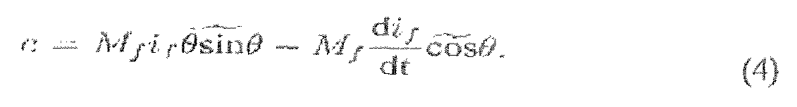
It is advantageous (but not essential) to assume that the field (rotor) winding is fed by an adjustable DC current source i/ instead of a voltage source v/. In this case, the terminal vokagc v/ varies, but this is irrelevant. As long as if is constant, the generated voltage of the virtual generator from (4) is

Define the generated real power P and reactive power Q as
P = (i, e) and Q = [i, ey,) ,
where eq has the same amplitude as e but with a phase delayed from that of e by


Then, the real power and reactive power are, respectively,


These coincide with the conventional definitions for real power and reactive power (note that the coefficient 3 is because there are three phases). When the voltage and current are in phase, i.e. when θ - φ = 0, the product of the rms values of the voltage and current gives the real power P, When the voltage and current
arc out of phase, this product gives reactive power Q. Moreover, inductors absorb reactive power with a positive Q (since
 ' i.e. the voltage
leads the current by
 ) while capacitors generate reactive power with a negative Q
(since
 i.e. the voltage lags the current by
 . The above two formulae about P and Q are very important when regulating the real and reactive power of a SG. However, it seems that the formula for reactive power has not been well documented in the literature and the reactive power has not been regarded as an important part of the SG model. Equation (6) can be written as
 where the input is the mechanical torque Tm, while the electromagnetic torque Te depends on i and θ, according to (7). This equation, together with (T), (8) and (9), are implemented in the electronic part of an SSG shown in Figure 3. Thus, the
state variables of the SSG are i (which are actual currents), θ and θ (which are a virtual angle and a virtual angular speed). The control inputs of the SSG are Tn, and Mfif. In order to operate the SSG in a useful way, we need a controller that generates the signals Tm and Λf// such that system stability is maintained and the desired values of real and reactive power arc followed. The significance of Q will be discussed in the next section.
where the input is the mechanical torque Tm, while the electromagnetic torque Te depends on i and θ, according to (7). This equation, together with (T), (8) and (9), are implemented in the electronic part of an SSG shown in Figure 3. Thus, the
state variables of the SSG are i (which are actual currents), θ and θ (which are a virtual angle and a virtual angular speed). The control inputs of the SSG are Tn, and Mfif. In order to operate the SSG in a useful way, we need a controller that generates the signals Tm and Λf// such that system stability is maintained and the desired values of real and reactive power arc followed. The significance of Q will be discussed in the next section.
B. The power part
The terminal voltages
 given in (3) can be obtained from the (local load) terminals va, v/, and vc of the inverter shown in Figure 2. The inductance Lx and resistance Rs of the inductor can be chosen to represent the stator impedance of a synchronous generator. The switches in the inverter are operated so that the average values of ea, <JJ, and ec over a switching period should be equal to e given in (8) and, hence no special pulse-width-modulation (PWM) techniques are necessary. Also shown in Figure 2 is a three-phase interfacing inductor L^/Rg and a circuit breaker to facilitate synchronisation/connection with the grid.
III. OPERATION OF AN SSG
A. Frequency drooping and regulation of real power
Tlic terms "real" and "reactive" power arc very well known in relation to AC power transmissioa The power flow resulting in net transfer of energy, over a complete AC cycle, is the real power. The power flow due to energy which is
stored and returned to the source over a cycle (by virtue of capacitance, inductance or equivalent) is the reactive power.
For synchronous generators, the rotor speed Ls maintained by the prime mover and it is known that the damping factor Dp is due to mechanical friction etc. In a real SG frequency tends to droop (fall) according to the real power delivered. This is important in the existing power distribution grid as it results in SGs sharing load. When the real power demand increases, the speed of the prime mover drops. The speed regulation system of the prime mover then increases the mechanical power, e.g. widening the throttle valve of an engine, so that a new power balance is achieved. This mechanism can be implemented by comparing the virtual angular
speed θ e.g. with an angular frequency reference '"' e,g, the nominal angular a speed "* , before feeding it into the damping block Dp - see the upper part of
Figure 4(a). As a result, the damping factor Dμ actually behaves as a frequency drooping coefficient, which is defined as the ratio of the required change of torque ΔT to the change of speed (frequency) Δθ. That is

Dp is defined as
 The mechanical torque T1n can be obtained from a set point
of real power Pstl after dividing by the nominal mechanical speed
 . This completes the feedback loop for real power; see the upper part of Figure 4(a). Because of the built-in frequency drooping mechanism, an SSG automatically
shares the load with other inverters of the same type connected on the same bus. The power regulation loop is very simple because no mechanical devices arc involved and no measurements are needed for real power regulation (all variables are available internally).
. This completes the feedback loop for real power; see the upper part of Figure 4(a). Because of the built-in frequency drooping mechanism, an SSG automatically
shares the load with other inverters of the same type connected on the same bus. The power regulation loop is very simple because no mechanical devices arc involved and no measurements are needed for real power regulation (all variables are available internally).
The regulation mechanism of the real power (torque) shown in the upper part of Figure 4(a) has a cascaded control structure, of which the inner loop is the frequency loop and the outer loop is the real power (torque) loop. The time constant of the frequency loop is

In other words, Jean be chosen as

Because there is no delay involved in the frequency drooping loop, the time constant Tt can be made much smaller than that of a physical synchronous generator. In order to make sure that the frequency loop has a quick response so that it can track the frequency reference quickly, T( should be made small. Hence, for a given frequency drooping coefficient Dp, J should be made small. This indicates that it is not necessary to have a large inertia for the virtual physical synchronous generator, although a larger inertia means that more energy can be stored. In other words, the energy storage tunction of an SSG can, and should, be decoupled from the inertia.
B. Yoltage drooping and regulation of reactive power
The regulation of reactive power Q flowing out of the SSG can be realised similarly. Define the voltage drooping coefficient Dp as the ratio of the required change of reactive power AQ to the change of voltage Δv, i.e.
 where Qn is the nominal reactive power, which can be chosen as the nominal power, and vn is the nominal amplitude of terminal voltage v. The regulation mechanism for the reactive power can be realised as shown in the lower part of Figure 4(a). The difference between the voltage reference vo e.g. the amplitude vΛ of the nominal voltage, and the amplitude vm of the actual terminal voltage v is amplified by the voltage drooping coefficient Dq before adding to the difference between the set point Qse, and the current reactive power Q, which is calculated according to (9). The resulting signal is then fed into an integrator with a
gain A to generate Mβ/ (here, K is dual to the inertia./). It is important to note that there is no need to measure reactive power Q as it is available internally.
The regulation mechanism of the reactive power shown in the lower part of Figure 4(a) has a cascaded control structure, if the effect of the LC filter 18 is ignored or compensated (wlu'ch means v = e). The inner loop is the (amplitude) voltage loop and the outer loop is the reactive power loop. The time constant of the voltage loop is

The amplitude vn, of the terminal voltage v can be obtained as follows. Assume

When the terminal voltages are balanced, i.e., when
 and
and
 ' then the last three terms in the above equality are balanced, having a doubled frequency. Hence,


In real implementation, a low-pass filter is needed to filter out the ripples at the doubled frequency as the terminal voltages may be unbalanced. This also applies to Te and Q.
C Operation modes of an SSG and its synchronisation
As shown above, an SSG can be operated in the same way as a synchronous generator under normal working conditions. An important process related to an
SSG or SG is the synchronisation procedure, prior to connection of the SSG/SG to another SSG/SG or to the public grid. This procedure involves bringing the terminal voltage v to be (almost) the same as the grid voltage vg on the other side of the circuit breaker 22, which means the same amplitude, the same frequency and the same phase angle. It is not an easy task to implement this for conventional SGs as this procedure involves much external equipment. For the SSG developed m this paper, this is relatively easy as the variables required are all available internally. A change of operation mode from island mode (in which the SSG operates without connection to a power grid) to grid-connected mode or vice verse can be implemented via a controlled multi-pole-double-throw (MPDT) switch 30a, b, Figure 4, with one throw for island mode (labelled as i) and the other for grid-connected mode (labelled as g), to change the frequency/voltage references. Whether an SSG works in island mode or grid-connected mode, the status of the MPDT switch 30a, b, is determined by the presence of the grid voltage and the status of a mode switch which sets the operation mode of the SSG. See Table 1 for the logic of operation. The default position of the mode switch is at "grid- connected" and it is turned to "island" when there is a fault. In grid-connected mode, the frequency/voltage references arc set as the corresponding values of the grid voltage vg and the integrator that produces phase θ, the electrical angle between the rotor field and the phasc-a field, is reset according to the grid phase when the circuit breaker is not turned on. There are many ways to obtain the grid
frequency -' and phase θs; one of them is to use a phase-locked bop (PLL), as shown at 32 in Figure 4, The amplitude Vgm of the voltage v^ on the grid side of
the circuit breaker can be calculated according to (10), replacing v with vg. In island mode, the references are set to the corresponding nominal values

When the voltage across the circuit breaker is small, the SSG can provide a green (go-ahead) signal for the operator to turn on the circuit breaker (it can be set to turn on automatically). The circuit breaker is allowed to be turned on in two cases: (1) when the MPDT switch i.g. is set at Throw g, i.e., when the grid voltage is present and the mode switch is turned at grid-connected mode; (2) when the grid voltage is not present and the mode switch is turned at island mode, which allows parallel operation of multiple inverters (to be discussed in more detail later).
After the circuit breaker is turned on, as the amplitude of the terminal voltage is set to follow that of the grid voltage, the voltage drooping mechanism disappears and the terminal voltage amplitude is determined by the grid. The frequency also
Table I THE LOGIC OF OPERATION FOR AN SSG (TRUTH TABLE)

If there is no grid voltage present, then an SSG works in island mode and the real power and reactive power delivered by the SSG are determined by the load. If there is more than one SSG to be connected in parallel, then the first one that is put into operation works with the mode switch set at "island" to establish the system frequency and voltage. Note that in this case the circuit breaker can be turned on straightaway, according to the logic of operation set in Table 1, so that the voltage is present on the other side of the circuit breaker, which allows other SSGs to synchronise with it and to join the system under the grid -connected mode. In this case, Pset and Qset should be set at 0 as the power delivered is determined by the local load.
D. Some practical issues
It is necessary to measure the terminal voltage v for the voltage drooping, the current i flowing out of the inverter for the calculation of Te P and Q the grid voltage vg for synchronisation A complete SSG consists of a power part shown in
Figure 2, and a complete electronic part shown in Figures 4(a) and (b), which are
interfaced with each other via and It can be seen that the nominal

 angular frequency
 and voltage (amplitude) vn are all set in the system via the
frequency reference
 and voltage reference v,. A resetting mechanism is added to the integrator generating θ to prevent numerical overflow under normal working condition and to obtain the same phase as the grid voltage during synchronisation. The phase of the SSG can be reset as 0 when the grid voltage crosses U, which is impossible for a physical synchronous generator. Another important mechanism is to add a constant phase shift θc to the phase θ so that the delay in the PWM switching process and the phase shift of the LC filter can be compensated, which brings the phase difference between v and vg to be minimal during synchronisation. The electronic part of an SSG can be implemented in a microcontroller (this is normally the case) and, hence, it is possible to use different values of Dμ(Dq) and J (K) when the SSG works in different modes.
Some guidelines on choosing Dμ and J are: (I) Dμ should be chosen to satisfy the frequency regulation requirement; (2) J should be chosen to achieve the desired frequency-loop time constant Tt;
Some guidelines on choosing Dq and K are: (1) D9 should be chosen to satisfy the voltage regulation requirement; (2) K should be chosen to achieve the desired voltage-loop time constant τv.
For relatively small inverters, Dn and (Dq) should be chosen so that the full step change of real and reactive power should not cause noticeable change in the frequency and voltage.
Table II PARAMETERS OF TIIE INVΕRTER-INFWTTE BUS SYSTEM

IV. SIMULATION RESULTS
The idea described above has been verified with simulations. The parameters of the inverter for carrying out the simulations arc given in Table II.
The frequency drooping coefficient is chosen as Dn = 0.2432 so that the frequency drops 0.5% when the torque (power) increases 100%. The virtual inertia is chosen as J=0.01 so that no-load time constant is roughly τf =0.04 second. The simulation was carried out in MATLAB® 7.4 with Simulink™. The solver used in the simulations is ode23tb with a relative tolerance 10-3 and a maximum step size of 10-4 second.
A. Grid-connected mode: Without voltage drooping
The inverter is connected to the grid via a circuit breaker and a step-up transformer. In this case, Dq - 0. The SSG was connected to the grid at /=1 second. The real power P=80W was applied at t=2 second by suitably setting Pset and the reactive power Q=60 Var was applied at t=3.5 second by means of Qset. In the simulations, a model of the LC filter and the interlacing inductor was included in the control algorithm so that it is possible to assume that the inverter was connected to the grid virtually inside the controller all the time (although the converter was not connected to the grid physically until t=1 second). The initial
state of was set at 100π. The drooping coefficient Dμ was reduced to 1% of its original value before any real power was applied and the inertia was reduced so that the no-load time constant WAS about 2 cycles before the inverter was connected to the grid.
The response of the SSG frequency is shown in Figure 5. The SSG quickly synchronised with the grid in about 10 cycles. No visible dynamics were seen after the SSG was connected to the grid at 2=1 second. When the SSG was requested to deliver 8OW real power to the grid, the frequency of the SSG increased and then returned to the grid frequency 50Hz after about 20 cycles. When the SSG was requested to deliver 60Var reactive power to the grid, the frequency of the SSG decreased slightly and then returned to the grid frequency quickly.
The output power of the SSG is shown in Figure 6. During the synchronisation period, there were some oscillations in the power (which is inside the controller as the hreaker is not yet turned on and hence it does not cause any problem). Before the SSG was requested to deliver power (i.e., before f=2 seconds), the real power and reactive power were zero. Then, the real power delivered to the grid gradually increased to the set point 8OW. During this transient process, the SSG initially took reactive power from the grid but returned to normal. At f=3.5 second, the reactive power delivered by the SSG increased to the sctpoint 60Var gradually. During this period, the real power increased slightly but then returned to the set point 8OW very quickly.
H. Island mode: With voltage drooping
In this case, Psel and Q,tt were set at 0 and Dy=144.0876 so that the voltage changes 5% if the reactive power changes 100%. The island mode is simulated by setting Rg=10000Ω. and Lg=0. The resistor R connected in parallel with C is reduced to 5Ω at t=2 second and C is increased to 660μF at t=3.5 second. The current i is not fed back to the system before /=0.1 second, i.e., before the voltage v is established.
The frequency curve is shown in Figure 8(a). After the real power applied at t=2 second, the frequency reduced to 49.855Hz, which further reduced to 49.842Hz alter the reactive load was applied. The real power and reactive power are shown in Figure 8(b). The change of the load caused some fast oscillations (spikes) in the curve. The amplitude of the terminal voltage is shown in Figure 8(c). Although
there were some fast oscillations (spikes) in the voltage when the load was changed, the voltage fell into the close range of the nominal value very quickly.
Claims
1. A control device for an inverter, the control device implementing a model of a synchronous generator comprising variables representing the angular position and rotational speed of a virtual generator rotor, logic for calculating a virtual electromagnetic torque acting on the virtual generator rotor from measured inverter output current and from a variable representing a virtual excitation current, logic tor calculating the rotational speed of the virtual rotor from the virtual electromagnetic torque and from al least one variable representing a virtual drive torque applied to the virtual generator rotor, and from a parameter representing the rotor's virtual inertia, and logic for calculating, from the variables representing angular position and rotational speed of the virtual generator rotor and from the variable representing the excitation current, a control signal for controlling the inverter to produce an AC output which corresponds to that of the virtual synchronous generator, the control device further comprising logic which implements a first feedback loop in which deviation of the rotational speed of the virtual generator rotor from a reference rotational speed is detected and used to adjust the virtual drive torque, thereby to regulate the angular speed of the virtual generator rotor, and hence to regulate frequency of the AC output from the inverter and the real power supplied by the inverter.
2. A control device as claimed in claim 1 further comprising logic implementing a second feedback loop in which deviation of a measured inverter output voltage from a reference value is detected and used in adjustment of the virtual excitation current, thereby to regulate the inverter output voltage.
3. A control device as claimed in claim 2 in which the deviation of reactive power from a reference level is detected and is used in adjustment of the virtual excitation current in the second feedback loop, thereby to regulate reactive power supplied by the inverter.
4. A control device as claimed in any preceding claim in which the first feedback loop receives as an input a nominal virtual drive torque, this being added to a correction to the virtual drive torque provided through the feedback loop to form the virtual drive torque and added to the virtual electromagnetic torque to determine the total virtual torque acting upon the virtual generator rotor.
5. A control device as claimed in claim 4 in which the total virtual torque acting upon the virtual rotor is integrated and divided by a virtual rotor momentum to determine the rotational speed of the virtual generator rotor.
6. A control device as claimed in claim 5 in which the difference between the rotational speed of the virtual generator rotor and a reference rotational speed, corresponding to the desired AC output frequency of the inverter, is multiplied by a frequency drooping coefficient to form the correction to the virtual drive torque.
7. A control device as claimed in any of claims 4 to 6 in which the nominal virtual drive torque is determined by dividing an input representing desired inverter real output power by a value representing the angular speed of the AC inverter output.
8. A control device as claimed in any preceding claim in which the virtual electromagnetic torque is calculated as the product of the measured inverter output current, the virtual excitation current, and a sin or cosine function of the angular position of the virtual generator rotor.
9. A control device as claimed in any preceding claim in which the inverter is controlled to provide an alternating output voltage determined from the model of the synchronous generator.
10. A control device as claimed in claim 9 in which the alternating output voltage to be provided by the inverter is calculated as the product of the rotational speed of the virtual generator rotor, the virtual excitation current, and a sin or cosine function of the angular position of the virtual generator rotor.
1 1. A control device as claimed in claim 10 in which the control signal for controlling the inverter is pulse width modulated to cause the inverter to provide the calculated alternating output voltage.
12. A control device as claimed in any claim 2, or claim 3, or in any subsequent claim when dependent on claim 2 or claim 3, in which, in the second feedback bop, the difference between reactive power and its reference level is added to a voltage drooping variable representing the deviation of the measured inverter output voltage from its reference value and is integrated to establish the virtual excitation current.
13. A control device as claimed in claim 12 in which the voltage drooping variable is established by multiplying the deviation of the measured inverter output voltage from its reference value by a voltage drooping coefficient.
14. A control device as claimed in claim 13 in which the measured inverter output voltage is the amplitude of the inverter's AC output.
15. Λ control device as claimed in any preceding claim for controlling an inverter which is to be connected to a power distribution grid, the control device comprising a device for detecting the AC frequency of the power distribution grid and using same to form the reference rotational speed used in the first feedback loop to control rotational speed of the virtual generator rotor.
16. A control device as claimed in claim 15 further comprising a device for detecting the AC phase of the power distribution grid, and for resetting the angular position of the virtual generator rotor to match the phase of the grid prior to connection of the inverter to the grid.
17. A control device as claimed in claim 16 in which the frequency and phase of the power distribution grid are obtained using a phase locked loop.
18. An apparatus tor regulating supply of electrical power from a power source, the apparatus comprising a control device as claimed in any preceding claim operatively connected to an inverter, and the inverter having at least one output line connectable via a circuit breaker to a power supply grid.
19. An apparatus as claimed in claim 18 comprising LC smoothing circuitry connected between the inverter and the circuit breaker.
20. An apparatus as claimed in claim 18 or claim 19 further comprising a coupling inductance in series between the inverter and the circuit breaker.
21. A method of controlling an inverter, comprising modelling of a synchronous generator by representing the angular position and rotational speed of a virtual generator rotor using numerical variables, measuring the inverter's output current, calculating a virtual electromagnetic torque acting on the virtual generator rotor from measured inverter output current and from a variable representing a virtual excitation current, calculating the rotational speed of the virtual rotor from the virtual electromagnetic torque and from at least one variable representing a virtual drive torque applied to the virtual generator rotor, and from a parameter representing the rotor's virtual inertia, and calculating, from the variables representing angular position and rotational speed of the virtual generator rotor and from the variable representing the excitation current, a control signal for controlling the inverter to produce an AC output which corresponds to that of the virtual synchronous generator, implementing a first feedback bop in which deviation of the rotational speed of the virtual generator rotor from a reference rotational speed is detected and used to adjust the virtual drive torque, thereby to regulate the rotational speed of the virtual generator rotor, and hence to regulate frequency of the AC output from the inverter and the real power supplied by the inverter.
22. A method as claimed in claim 21 further comprising implementing a second feedback loop in which deviation of a measured inverter output voltage from a reference value ts detected and used in adjustment of the virtual excitation current, thereby to regulate the inverter output voltage.
23. A method as claimed in claim 23 in which the deviation of reactive power from a reference level is detected and is used in adjustment of the virtual excitation current in the second feedback loop, thereby to regulate reactive power supplied by the inverter.
Priority Applications (4)
| Application Number | Priority Date | Filing Date | Title |
|---|---|---|---|
| US13/128,540 US8880236B2 (en) | 2008-11-12 | 2009-10-29 | Static synchronous generators |
| CN200980151605.8A CN102257720B (en) | 2008-11-12 | 2009-10-29 | Method and equipment for controlling inverter to simulate static synchronous generato |
| ES09756165.8T ES2548786T3 (en) | 2008-11-12 | 2009-10-29 | Static synchronous generators |
| EP09756165.8A EP2377238B1 (en) | 2008-11-12 | 2009-10-29 | Static synchronous generators |
Applications Claiming Priority (2)
| Application Number | Priority Date | Filing Date | Title |
|---|---|---|---|
| GB0820699.7 | 2008-11-12 | ||
| GBGB0820699.7A GB0820699D0 (en) | 2008-11-12 | 2008-11-12 | Static synchronous generators |
Publications (2)
| Publication Number | Publication Date |
|---|---|
| WO2010055322A2 true WO2010055322A2 (en) | 2010-05-20 |
| WO2010055322A3 WO2010055322A3 (en) | 2010-07-22 |
Family
ID=40139800
Family Applications (1)
| Application Number | Title | Priority Date | Filing Date |
|---|---|---|---|
| PCT/GB2009/051460 WO2010055322A2 (en) | 2008-11-12 | 2009-10-29 | Static synchronous generators |
Country Status (6)
| Country | Link |
|---|---|
| US (1) | US8880236B2 (en) |
| EP (1) | EP2377238B1 (en) |
| CN (1) | CN102257720B (en) |
| ES (1) | ES2548786T3 (en) |
| GB (1) | GB0820699D0 (en) |
| WO (1) | WO2010055322A2 (en) |
Cited By (14)
| Publication number | Priority date | Publication date | Assignee | Title |
|---|---|---|---|---|
| CN102157937A (en) * | 2011-04-08 | 2011-08-17 | 华北电力大学 | Inverse system-based active and reactive power independent control method for microgrid |
| WO2012117131A1 (en) | 2011-02-28 | 2012-09-07 | Abengoa Solar New Technologies, S.A. | Synchronous power controller for a generating system based on static power converters |
| EP2683076A1 (en) | 2011-02-28 | 2014-01-08 | Abengoa Solar New Technologies, S.A. | Virtual admittance controller based on static power converters |
| EP2683075A1 (en) | 2011-02-28 | 2014-01-08 | Abengoa Solar New Technologies, S.A. | Virtual controller of electromechanical characteristics for static power converters |
| CN104734598A (en) * | 2015-03-31 | 2015-06-24 | 西安交通大学 | Virtual synchronous motor control method based on band-pass damping voltage type converter |
| CN104953617A (en) * | 2015-06-17 | 2015-09-30 | 清华大学 | Virtual synchronous generator on-load grid-connection control method and system |
| US9300142B2 (en) | 2010-01-26 | 2016-03-29 | Vestas Wind Systems A/S | Method for emulation of synchronous machine |
| CN105915140A (en) * | 2016-04-22 | 2016-08-31 | 广东电网有限责任公司电力科学研究院 | Decoupling control method based on virtual synchronous generator and decoupling control device thereof |
| EP2407664A3 (en) * | 2010-06-23 | 2016-09-21 | Vestas Wind Systems A/S | Method of Operating a Wind Turbine, Controller Usable for Operating a Wind Turbine, and Wind Turbine |
| CN108462206A (en) * | 2018-03-30 | 2018-08-28 | 华北电力科学研究院有限责任公司 | The virtual inertia of VSG and the optional range determining method and device of damped coefficient |
| CN108599264A (en) * | 2018-05-10 | 2018-09-28 | 上海交通大学 | A kind of voltage to frequency non differential regulation method based on virtual synchronous generator control |
| WO2018229088A1 (en) * | 2017-06-13 | 2018-12-20 | Wobben Properties Gmbh | Method for supplying electric power by means of a converter-controlled generator unit, in particular a wind turbine |
| WO2019187411A1 (en) * | 2018-03-28 | 2019-10-03 | 株式会社日立製作所 | Control device for distributed power source |
| WO2022009101A1 (en) * | 2020-07-08 | 2022-01-13 | Ramot At Tel-Aviv University Ltd. | Virtual synchronous machines with improved voltage and frequency control |
Families Citing this family (38)
| Publication number | Priority date | Publication date | Assignee | Title |
|---|---|---|---|---|
| JP2013162623A (en) * | 2012-02-03 | 2013-08-19 | Toshiba Corp | Power supply system |
| JP5953077B2 (en) * | 2012-03-13 | 2016-07-13 | 東芝三菱電機産業システム株式会社 | Inverter test equipment |
| JP6084863B2 (en) * | 2013-02-28 | 2017-02-22 | 川崎重工業株式会社 | Power converter for grid connection |
| JP6386718B2 (en) * | 2013-11-20 | 2018-09-05 | 川崎重工業株式会社 | Power converter |
| CN103972928B (en) * | 2014-04-18 | 2016-05-25 | 国家电网公司 | The micro-operated control method of a kind of microgrid based on virtual synchronous generator |
| CN105186554B (en) * | 2015-08-14 | 2017-09-29 | 许继集团有限公司 | The virtual synchronous generator method for becoming excellent certainly with rotary inertia and damping |
| CN105281596B (en) * | 2015-10-30 | 2018-01-23 | 清华大学 | The electronics commutation control system and control method of variable capacitance electrostatic motor |
| CN105743130B (en) * | 2016-03-22 | 2018-03-02 | 西安交通大学 | The method for improving virtual synchronous generator reactive power dynamic response performance |
| US9970417B2 (en) | 2016-04-14 | 2018-05-15 | General Electric Company | Wind converter control for weak grid |
| US10177574B2 (en) * | 2016-09-28 | 2019-01-08 | Nec Corporation | Dynamic frequency control scheme for microgrids using energy storage |
| CN106505617B (en) * | 2016-11-18 | 2019-02-22 | 国网青海省电力公司 | A kind of photovoltaic micro frequency recovery method and system |
| CN108242882B (en) * | 2016-12-27 | 2022-02-15 | 顺涞新能源环保科技(深圳)有限公司 | High magnetic energy AC/DC generator with multiple groups of series-connected generating mechanisms |
| JP6809753B2 (en) * | 2016-12-28 | 2021-01-06 | 川崎重工業株式会社 | Combined cycle system |
| CN106655272B (en) * | 2017-01-16 | 2018-12-04 | 湖南大学 | Inhibit failure temporary impact current mode virtual synchronous inverter and its control method |
| EP3872949A1 (en) | 2017-03-14 | 2021-09-01 | ABB Schweiz AG | Method and control system for controlling a power converter |
| GB2563086B (en) | 2017-06-04 | 2020-09-16 | Zhong Qingchang | Cyber Synchronous Machine (in short, Cybersync Machine) |
| CN107196344B (en) * | 2017-06-06 | 2020-05-05 | 湖南大学 | Self-synchronizing virtual synchronous inverter grid-connected controller and method with local load based on SPF-PLL |
| CN107612043B (en) * | 2017-09-18 | 2020-03-17 | 西安交通大学 | Virtual synchronous generator control method based on phase feedforward |
| CN107565604B (en) * | 2017-10-25 | 2020-05-19 | 合肥工业大学 | Power distribution and parameter self-adaptive control method for multi-machine parallel virtual synchronous generator |
| JP7052290B2 (en) * | 2017-10-27 | 2022-04-12 | 東京電力ホールディングス株式会社 | AC / DC converter controller |
| GB2570151B (en) * | 2018-01-14 | 2020-07-15 | Zhong Qingchang | Reconfiguration of inertia, damping, and fault ride-through for a virtual synchronous machine |
| CN108363007B (en) * | 2018-02-27 | 2024-03-29 | 华北电力科学研究院有限责任公司 | Photovoltaic virtual synchronous generator performance testing device and method |
| GB2574645B (en) * | 2018-06-14 | 2020-07-15 | Zhong Qingchang | Passive virtual synchronous machine with bounded frequency and virtual flux |
| CN108923454B (en) * | 2018-06-29 | 2022-09-02 | 中国电力科学研究院有限公司 | Control method and device for load virtual synchronous machine with voltage droop on direct current side |
| CN109193810B (en) * | 2018-09-06 | 2022-04-12 | 易事特集团股份有限公司 | Synchronous inverter control method, device and system |
| EP3647586A1 (en) * | 2018-10-29 | 2020-05-06 | GE Renewable Technologies | Method for starting a hydraulic turbine |
| CN113474989A (en) * | 2018-12-28 | 2021-10-01 | 维斯塔斯风力系统集团公司 | Wind turbine with virtual synchronous generator and DC link control |
| CN111835028A (en) * | 2019-04-15 | 2020-10-27 | 南京理工大学 | Microgrid inverter control method based on virtual synchronous generator |
| CN110112769B (en) * | 2019-04-16 | 2023-03-31 | 西安理工大学 | Output feedback self-adaptive control method for virtual synchronous machine |
| CN110739722B (en) * | 2019-10-24 | 2021-04-27 | 合肥工业大学 | Active standby variable inertia virtual synchronous control method for cascade inverter |
| CN110890765B (en) * | 2019-11-19 | 2021-04-02 | 山东大学 | Dynamic rotating speed protection method and system for virtual inertia frequency modulation of doubly-fed wind turbine |
| CN110957741A (en) * | 2019-12-30 | 2020-04-03 | 南京师范大学 | Reactive response control system for demand side back-to-back converter |
| JP6735039B1 (en) * | 2020-03-19 | 2020-08-05 | 富士電機株式会社 | Grid-connected inverter and grid frequency fluctuation suppression method |
| CN112271737B (en) * | 2020-07-30 | 2022-08-05 | 合肥工业大学 | Virtual synchronous machine strong power network stability control method based on inductive current differential feedback |
| CN112039131B (en) * | 2020-08-07 | 2022-01-25 | 国电南瑞南京控制系统有限公司 | Virtual synchronous machine-based dual-machine parallel system power distribution method and system |
| US11456645B2 (en) | 2020-12-10 | 2022-09-27 | General Electric Renovables Espana, S.L. | System and method for operating an asynchronous inverter-based resource as a virtual synchronous machine with storage |
| US11671039B2 (en) | 2020-12-10 | 2023-06-06 | General Electric Renovables Espana, S.L. | System and method for operating an asynchronous inverter-based resource as a virtual synchronous machine to provide grid-forming control thereof |
| CN114069697B (en) * | 2021-11-16 | 2023-11-17 | 福州大学 | Method for controlling inverter grid connection based on virtual synchronous generator principle |
Citations (7)
| Publication number | Priority date | Publication date | Assignee | Title |
|---|---|---|---|---|
| US5256944A (en) * | 1990-09-07 | 1993-10-26 | Hitachi, Ltd. | Motor speed control method and apparatus with drooping compensation independent of acceleration or deceleration current and time constant of motor |
| JPH10122119A (en) * | 1996-10-22 | 1998-05-12 | Mitsubishi Electric Corp | Speed governing control device for water turbine and reversible pump-turbine and method thereof |
| US20060268587A1 (en) * | 2005-03-30 | 2006-11-30 | Alstom Technology Ltd | Method to control a frequency converter |
| EP1758239A2 (en) * | 2005-08-25 | 2007-02-28 | International Rectifier Corporation | Self tuning method and apparatus for permanent magnet motor sensorless control |
| WO2007066182A1 (en) * | 2005-12-08 | 2007-06-14 | Toyota Jidosha Kabushiki Kaisha | Control apparatus and method for motor drive system |
| FR2901647A1 (en) * | 2006-05-23 | 2007-11-30 | Denso Corp | Excitation current controlling device for e.g. three phase field winding type dynamoelectric machine, has power estimating circuit estimating power of machine based on preset relation among detected current, speed and power |
| US20080116842A1 (en) * | 2006-11-17 | 2008-05-22 | Bing Cheng | Method and apparatus for motor control |
Family Cites Families (12)
| Publication number | Priority date | Publication date | Assignee | Title |
|---|---|---|---|---|
| DE10011929B4 (en) * | 2000-03-11 | 2004-07-01 | Wobben, Aloys, Dipl.-Ing. | synchronous generator |
| US7180263B2 (en) * | 2000-11-09 | 2007-02-20 | Daikin Industries, Ltd. | Synchronous motor control method and device |
| JP2002204597A (en) * | 2001-01-05 | 2002-07-19 | Honda Motor Co Ltd | Inverter-control type generator |
| DE10220122A1 (en) * | 2001-05-30 | 2002-12-19 | Continental Teves Ag & Co Ohg | Method and circuit arrangement for sensorless, electrical rotor position measurement of a permanently excited synchronous machine |
| US7680642B2 (en) * | 2005-01-12 | 2010-03-16 | The Japan Research Institute, Limited | Equivalent circuit for coil incorporated in circuit simulator, circuit simulator and method of preparation of same, and storage medium of circuit simulator program |
| US7592761B2 (en) * | 2005-09-29 | 2009-09-22 | Agile Systems Inc. | System and method for starting and operating a motor |
| US20070069677A1 (en) * | 2005-09-29 | 2007-03-29 | Mackay David K | System and method for applying energy to a motor |
| US7279860B2 (en) * | 2005-09-29 | 2007-10-09 | Agile Systems Inc. | System and method for evaluating back electromotive force in a motor |
| US7477034B2 (en) * | 2005-09-29 | 2009-01-13 | Agile Systems Inc. | System and method for commutating a motor using back electromotive force signals |
| US7256564B2 (en) * | 2005-09-29 | 2007-08-14 | Agile Systems Inc. | System and method for attenuating noise associated with a back electromotive force signal in a motor |
| US7288911B2 (en) * | 2005-09-29 | 2007-10-30 | Agile Systems Inc. | System and method for commutating a motor |
| US7881814B2 (en) * | 2006-05-04 | 2011-02-01 | General Electric Company | Method and system for rapid modeling and verification of excitation systems for synchronous generators |
-
2008
- 2008-11-12 GB GBGB0820699.7A patent/GB0820699D0/en active Pending
-
2009
- 2009-10-29 WO PCT/GB2009/051460 patent/WO2010055322A2/en active Application Filing
- 2009-10-29 CN CN200980151605.8A patent/CN102257720B/en active Active
- 2009-10-29 EP EP09756165.8A patent/EP2377238B1/en active Active
- 2009-10-29 ES ES09756165.8T patent/ES2548786T3/en active Active
- 2009-10-29 US US13/128,540 patent/US8880236B2/en active Active
Patent Citations (7)
| Publication number | Priority date | Publication date | Assignee | Title |
|---|---|---|---|---|
| US5256944A (en) * | 1990-09-07 | 1993-10-26 | Hitachi, Ltd. | Motor speed control method and apparatus with drooping compensation independent of acceleration or deceleration current and time constant of motor |
| JPH10122119A (en) * | 1996-10-22 | 1998-05-12 | Mitsubishi Electric Corp | Speed governing control device for water turbine and reversible pump-turbine and method thereof |
| US20060268587A1 (en) * | 2005-03-30 | 2006-11-30 | Alstom Technology Ltd | Method to control a frequency converter |
| EP1758239A2 (en) * | 2005-08-25 | 2007-02-28 | International Rectifier Corporation | Self tuning method and apparatus for permanent magnet motor sensorless control |
| WO2007066182A1 (en) * | 2005-12-08 | 2007-06-14 | Toyota Jidosha Kabushiki Kaisha | Control apparatus and method for motor drive system |
| FR2901647A1 (en) * | 2006-05-23 | 2007-11-30 | Denso Corp | Excitation current controlling device for e.g. three phase field winding type dynamoelectric machine, has power estimating circuit estimating power of machine based on preset relation among detected current, speed and power |
| US20080116842A1 (en) * | 2006-11-17 | 2008-05-22 | Bing Cheng | Method and apparatus for motor control |
Cited By (28)
| Publication number | Priority date | Publication date | Assignee | Title |
|---|---|---|---|---|
| US9300142B2 (en) | 2010-01-26 | 2016-03-29 | Vestas Wind Systems A/S | Method for emulation of synchronous machine |
| EP2407664A3 (en) * | 2010-06-23 | 2016-09-21 | Vestas Wind Systems A/S | Method of Operating a Wind Turbine, Controller Usable for Operating a Wind Turbine, and Wind Turbine |
| EP2683076A4 (en) * | 2011-02-28 | 2017-03-29 | Abengoa Solar New Technologies, S.A. | Virtual admittance controller based on static power converters |
| EP2683075A1 (en) | 2011-02-28 | 2014-01-08 | Abengoa Solar New Technologies, S.A. | Virtual controller of electromechanical characteristics for static power converters |
| EP2683075A4 (en) * | 2011-02-28 | 2017-10-04 | Abengoa Solar New Technologies, S.A. | Virtual controller of electromechanical characteristics for static power converters |
| CN103548250A (en) * | 2011-02-28 | 2014-01-29 | 阿文戈亚太阳能新技术公司 | Synchronous power controller for a generating system based on static power converters |
| JP2014509179A (en) * | 2011-02-28 | 2014-04-10 | アベンゴア ソーラー ニュー テクノロジーズ ソシエダ アノニマ | Synchronous power controller for power generation system based on static power converter |
| EP2683076A1 (en) | 2011-02-28 | 2014-01-08 | Abengoa Solar New Technologies, S.A. | Virtual admittance controller based on static power converters |
| US9166508B2 (en) | 2011-02-28 | 2015-10-20 | Abengoa Solar New Technologies, S.A. | Synchronous power controller for a generating system based on static power converters |
| ES2402467A1 (en) * | 2011-02-28 | 2013-05-03 | Abengoa Solar New Technologies S.A. | Synchronous power controller for a generating system based on static power converters |
| EP4016832A1 (en) | 2011-02-28 | 2022-06-22 | Wobben Properties GmbH | Inverter power-controller for a generating system based on a static power converter |
| WO2012117131A1 (en) | 2011-02-28 | 2012-09-07 | Abengoa Solar New Technologies, S.A. | Synchronous power controller for a generating system based on static power converters |
| EP2683077A1 (en) | 2011-02-28 | 2014-01-08 | Abengoa Solar New Technologies, S.A. | Synchronous power controller for a generating system based on static power converters |
| CN102157937A (en) * | 2011-04-08 | 2011-08-17 | 华北电力大学 | Inverse system-based active and reactive power independent control method for microgrid |
| CN104734598A (en) * | 2015-03-31 | 2015-06-24 | 西安交通大学 | Virtual synchronous motor control method based on band-pass damping voltage type converter |
| CN104953617A (en) * | 2015-06-17 | 2015-09-30 | 清华大学 | Virtual synchronous generator on-load grid-connection control method and system |
| CN105915140A (en) * | 2016-04-22 | 2016-08-31 | 广东电网有限责任公司电力科学研究院 | Decoupling control method based on virtual synchronous generator and decoupling control device thereof |
| CN110800181B (en) * | 2017-06-13 | 2024-04-12 | 乌本产权有限公司 | Method for supplying electrical power by means of a generator set, in particular a wind energy installation, controlled by a converter |
| WO2018229088A1 (en) * | 2017-06-13 | 2018-12-20 | Wobben Properties Gmbh | Method for supplying electric power by means of a converter-controlled generator unit, in particular a wind turbine |
| CN110800181A (en) * | 2017-06-13 | 2020-02-14 | 乌本产权有限公司 | Method for feeding electric power by means of converter-controlled generator sets, in particular wind turbines |
| RU2729059C1 (en) * | 2017-06-13 | 2020-08-04 | Воббен Пропертиз Гмбх | Electric power supply method by means of converter-controlled generator unit, in particular, wind-driven power plant |
| US11196370B2 (en) | 2017-06-13 | 2021-12-07 | Wobben Properties Gmbh | Method for supplying electric power by means of a converter-controlled generator unit, in particular a wind turbine |
| WO2019187411A1 (en) * | 2018-03-28 | 2019-10-03 | 株式会社日立製作所 | Control device for distributed power source |
| JP2019176584A (en) * | 2018-03-28 | 2019-10-10 | 株式会社日立製作所 | Distributed power source control device |
| JP7025973B2 (en) | 2018-03-28 | 2022-02-25 | 株式会社日立製作所 | Distributed generation controller |
| CN108462206A (en) * | 2018-03-30 | 2018-08-28 | 华北电力科学研究院有限责任公司 | The virtual inertia of VSG and the optional range determining method and device of damped coefficient |
| CN108599264A (en) * | 2018-05-10 | 2018-09-28 | 上海交通大学 | A kind of voltage to frequency non differential regulation method based on virtual synchronous generator control |
| WO2022009101A1 (en) * | 2020-07-08 | 2022-01-13 | Ramot At Tel-Aviv University Ltd. | Virtual synchronous machines with improved voltage and frequency control |
Also Published As
| Publication number | Publication date |
|---|---|
| CN102257720A (en) | 2011-11-23 |
| CN102257720B (en) | 2014-09-10 |
| GB0820699D0 (en) | 2008-12-17 |
| US20110270463A1 (en) | 2011-11-03 |
| WO2010055322A3 (en) | 2010-07-22 |
| EP2377238B1 (en) | 2015-07-08 |
| US8880236B2 (en) | 2014-11-04 |
| ES2548786T3 (en) | 2015-10-20 |
| EP2377238A2 (en) | 2011-10-19 |
Similar Documents
| Publication | Publication Date | Title |
|---|---|---|
| EP2377238B1 (en) | Static synchronous generators | |
| CN108832657B (en) | Control method for virtual synchronous motor of alternating current-direct current hybrid microgrid bidirectional power converter | |
| CN107863786B (en) | Bidirectional power converter control method based on virtual synchronous motor | |
| Zhong et al. | Synchronverters: Inverters that mimic synchronous generators | |
| Amin et al. | Development of high-performance grid-connected wind energy conversion system for optimum utilization of variable speed wind turbines | |
| Flannery et al. | Evaluation of voltage sag ride-through of a doubly fed induction generator wind turbine with series grid side converter | |
| Benkahla et al. | Comparative study of robust control strategies for a DFIG-based wind turbine | |
| Choudhury et al. | Performance analysis of doublyfed induction generator for wind energy conversion system | |
| CN107005049B (en) | Power controller and power control method | |
| Liu et al. | Sensorless direct voltage control of the stand-alone brushless doubly-fed generator | |
| Shukla et al. | Instantaneous direct voltage and frequency control in DC grid tied DFIG based wind energy system | |
| Rajan et al. | Synchronverter based HVDC transmission | |
| Li et al. | New control schemes of output power decoupling based on synchronverter | |
| Luna et al. | Control of DFIG-WT under unbalanced grid voltage conditions | |
| Rodriguez et al. | Grid-following and grid-forming PV and wind turbines | |
| Singh et al. | Power control in centralized distributed AC load for wind energy system | |
| Raju et al. | Enhanced decoupled power control of wind turbine driven DFIG using DVR under unbalanced grid voltage | |
| Bouzid et al. | Voltage and frequency control of wind-powered islanded microgrids based on induction generator and STATCOM | |
| Abdessemad et al. | A novel control scheme implementation for a self-excited asynchronous generator | |
| Chatterjee et al. | Shaft input adaptive source current compensation based novel voltage and frequency control of autonomous induction generator | |
| Amin et al. | Phase-Frequency Controlled In Virtual Synchronous Converter for Low-Voltage Microgrid-Inverter Synchronization | |
| Ion et al. | Single-phase operation of an autonomous three-phase induction generator using a VSI-DL control system | |
| CN116111867B (en) | Virtual instantaneous power-based grid-structured energy storage converter presynchronization control method | |
| Trujillo et al. | Real-time Simulation of Synchronverter Connected to the Main Grid | |
| Shaalan et al. | Improvement of Microgrid (MG) Systems Using Synchronverters (SVs) |
Legal Events
| Date | Code | Title | Description |
|---|---|---|---|
| WWE | Wipo information: entry into national phase |
Ref document number: 200980151605.8 Country of ref document: CN |
|
| 121 | Ep: the epo has been informed by wipo that ep was designated in this application |
Ref document number: 09756165 Country of ref document: EP Kind code of ref document: A2 |
|
| NENP | Non-entry into the national phase |
Ref country code: DE |
|
| WWE | Wipo information: entry into national phase |
Ref document number: 2009756165 Country of ref document: EP |
|
| WWE | Wipo information: entry into national phase |
Ref document number: 13128540 Country of ref document: US |