EP2377238B1 - Static synchronous generators - Google Patents
Static synchronous generators Download PDFInfo
- Publication number
- EP2377238B1 EP2377238B1 EP09756165.8A EP09756165A EP2377238B1 EP 2377238 B1 EP2377238 B1 EP 2377238B1 EP 09756165 A EP09756165 A EP 09756165A EP 2377238 B1 EP2377238 B1 EP 2377238B1
- Authority
- EP
- European Patent Office
- Prior art keywords
- virtual
- inverter
- rotor
- rotational speed
- control device
- Prior art date
- Legal status (The legal status is an assumption and is not a legal conclusion. Google has not performed a legal analysis and makes no representation as to the accuracy of the status listed.)
- Active
Links
- 230000001360 synchronised effect Effects 0.000 title claims description 41
- 230000003068 static effect Effects 0.000 title description 7
- 230000005284 excitation Effects 0.000 claims description 16
- 238000000034 method Methods 0.000 claims description 11
- 238000013016 damping Methods 0.000 claims description 9
- 238000004804 winding Methods 0.000 description 12
- 230000008859 change Effects 0.000 description 11
- 238000004088 simulation Methods 0.000 description 11
- 230000007246 mechanism Effects 0.000 description 6
- 230000007935 neutral effect Effects 0.000 description 6
- 238000006243 chemical reaction Methods 0.000 description 4
- 230000004907 flux Effects 0.000 description 4
- 230000001276 controlling effect Effects 0.000 description 3
- 230000003278 mimic effect Effects 0.000 description 3
- 230000010355 oscillation Effects 0.000 description 3
- 230000008569 process Effects 0.000 description 3
- 230000001105 regulatory effect Effects 0.000 description 3
- 230000008844 regulatory mechanism Effects 0.000 description 3
- 238000004458 analytical method Methods 0.000 description 2
- 230000005540 biological transmission Effects 0.000 description 2
- 239000003990 capacitor Substances 0.000 description 2
- 230000008878 coupling Effects 0.000 description 2
- 238000010168 coupling process Methods 0.000 description 2
- 238000005859 coupling reaction Methods 0.000 description 2
- 238000010586 diagram Methods 0.000 description 2
- 230000000694 effects Effects 0.000 description 2
- 230000005611 electricity Effects 0.000 description 2
- 238000004146 energy storage Methods 0.000 description 2
- 238000013178 mathematical model Methods 0.000 description 2
- 230000010363 phase shift Effects 0.000 description 2
- 230000004044 response Effects 0.000 description 2
- XEEYBQQBJWHFJM-UHFFFAOYSA-N Iron Chemical group [Fe] XEEYBQQBJWHFJM-UHFFFAOYSA-N 0.000 description 1
- 238000003491 array Methods 0.000 description 1
- 238000004422 calculation algorithm Methods 0.000 description 1
- 238000004364 calculation method Methods 0.000 description 1
- 238000010276 construction Methods 0.000 description 1
- 230000003247 decreasing effect Effects 0.000 description 1
- 230000003111 delayed effect Effects 0.000 description 1
- 230000009977 dual effect Effects 0.000 description 1
- 230000007613 environmental effect Effects 0.000 description 1
- 238000001914 filtration Methods 0.000 description 1
- 230000003993 interaction Effects 0.000 description 1
- 238000005259 measurement Methods 0.000 description 1
- 238000010248 power generation Methods 0.000 description 1
- 230000001052 transient effect Effects 0.000 description 1
Images


Classifications
-
- H—ELECTRICITY
- H02—GENERATION; CONVERSION OR DISTRIBUTION OF ELECTRIC POWER
- H02P—CONTROL OR REGULATION OF ELECTRIC MOTORS, ELECTRIC GENERATORS OR DYNAMO-ELECTRIC CONVERTERS; CONTROLLING TRANSFORMERS, REACTORS OR CHOKE COILS
- H02P9/00—Arrangements for controlling electric generators for the purpose of obtaining a desired output
- H02P9/02—Details
-
- H—ELECTRICITY
- H02—GENERATION; CONVERSION OR DISTRIBUTION OF ELECTRIC POWER
- H02P—CONTROL OR REGULATION OF ELECTRIC MOTORS, ELECTRIC GENERATORS OR DYNAMO-ELECTRIC CONVERTERS; CONTROLLING TRANSFORMERS, REACTORS OR CHOKE COILS
- H02P23/00—Arrangements or methods for the control of AC motors characterised by a control method other than vector control
- H02P23/12—Observer control, e.g. using Luenberger observers or Kalman filters
-
- H—ELECTRICITY
- H02—GENERATION; CONVERSION OR DISTRIBUTION OF ELECTRIC POWER
- H02P—CONTROL OR REGULATION OF ELECTRIC MOTORS, ELECTRIC GENERATORS OR DYNAMO-ELECTRIC CONVERTERS; CONTROLLING TRANSFORMERS, REACTORS OR CHOKE COILS
- H02P23/00—Arrangements or methods for the control of AC motors characterised by a control method other than vector control
- H02P23/14—Estimation or adaptation of motor parameters, e.g. rotor time constant, flux, speed, current or voltage
-
- H—ELECTRICITY
- H02—GENERATION; CONVERSION OR DISTRIBUTION OF ELECTRIC POWER
- H02P—CONTROL OR REGULATION OF ELECTRIC MOTORS, ELECTRIC GENERATORS OR DYNAMO-ELECTRIC CONVERTERS; CONTROLLING TRANSFORMERS, REACTORS OR CHOKE COILS
- H02P9/00—Arrangements for controlling electric generators for the purpose of obtaining a desired output
- H02P9/14—Arrangements for controlling electric generators for the purpose of obtaining a desired output by variation of field
- H02P9/26—Arrangements for controlling electric generators for the purpose of obtaining a desired output by variation of field using discharge tubes or semiconductor devices
- H02P9/30—Arrangements for controlling electric generators for the purpose of obtaining a desired output by variation of field using discharge tubes or semiconductor devices using semiconductor devices
-
- H—ELECTRICITY
- H02—GENERATION; CONVERSION OR DISTRIBUTION OF ELECTRIC POWER
- H02P—CONTROL OR REGULATION OF ELECTRIC MOTORS, ELECTRIC GENERATORS OR DYNAMO-ELECTRIC CONVERTERS; CONTROLLING TRANSFORMERS, REACTORS OR CHOKE COILS
- H02P2101/00—Special adaptation of control arrangements for generators
- H02P2101/15—Special adaptation of control arrangements for generators for wind-driven turbines
Definitions
- This equation, together with (7), (8) and (9), are implemented in the electronic part of an SSG shown in Figure 3 .
- the state variables of the SSG are i (which are actual currents), ⁇ and ⁇ (which are a virtual angle and a virtual angular speed).
- the control inputs of the SSG are T m and M f i f .
- a controller that generates the signals T m and M f i f such that system stability is maintained and the desired values of real and reactive power are followed. The significance of Q will be discussed in the next section.
- D p is defined as ⁇ ⁇ ⁇ ⁇ ⁇ T .
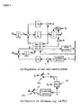
- the mechanical torque T m can be obtained from a set point of real power P set after dividing by the nominal mechanical speed ⁇ ⁇ a p . This completes the feedback loop for real power; see the upper part of Figure 4(a) . Because of the built-in frequency drooping mechanism, an SSG automatically shares the load with other inverters of the same type connected on the same bus. The power regulation loop is very simple because no mechanical devices arc involved and no measurements are needed for real power regulation (all variables are available internally).
- the time constant ⁇ f can be made much smaller than that of a physical synchronous generator.
- ⁇ f should be made small.
- J should be made small. This indicates that it is not necessary to have a large inertia for the virtual physical synchronous generator, although a larger inertia means that more energy can be stored. In other words, the energy storage function of an SSG can, and should, be decoupled from the inertia.
- the regulation of reactive power Q flowing out of the SSG can be realised similarly.
- the regulation mechanism for the reactive power can be realised as shown in the lower part of Figure 4(a) .
- the difference between the voltage reference v r e.g.
- the inner loop is the (amplitude) voltage loop and the outer loop is the reactive power loop.
- ⁇ a ⁇ ⁇ b + ⁇ b ⁇ ⁇ c + ⁇ c ⁇ ⁇ a - 3 4 ⁇ ⁇ m 2
- an SSG can be operated in the same way as a synchronous generator under normal working conditions.
- An important process related to an SSG or SG is the synchronisation procedure, prior to connection of the SSG/SG to another SSG/SG or to the public grid. This procedure involves bringing the terminal voltage v to be (almost) the same as the grid voltage v g on the other side of the circuit breaker 22, which means the same amplitude, the same frequency and the same phase angle. It is not an easy task to implement this for conventional SGs as this procedure involves much external equipment. For the SSG developed in this paper, this is relatively easy as the variables required are all available internally.
- a complete SSG consists of a power part shown in Figure 2 , and a complete electronic part shown in Figures 4(a) and (b) , which are interfaced with each other via ⁇ r , ⁇ y and v r . It can be seen that the nominal angular frequency ⁇ n and voltage (amplitude) v n are all set in the system via the frequency reference ⁇ r and voltage reference v r .
- D p and (D q ) should be chosen so that the full step change of real and reactive power should not cause noticeable change in the frequency and voltage.
- Table II PARAMETERS OF THE INVERTER-INFINITE BUS SYSTEM Parameters Values Parameters Values L s 0.15 mII L g 0.0534 mH R s 0.045 ⁇ R g 0.06 ⁇ C 22 ⁇ F Frequency 50 Hz R (parallel to C ) 1000 ⁇ Voltage (line-line) 17 Vrms Rated power 100 W Initial grid phase 0° Inertia J 0.01 Kgm 2 K 13580
Description
- The present invention is concerned with a control device for an inverter associated with an electrical power supply. Specifically, the control device causes the power supply and inverter together to mimic in some respects the behaviour of a synchronous electrical generator.
- For economic, technical and environmental reasons, more and more distributed energy sources, such as combined heat and power (CHP) plants, and renewable energy sources, such as wind power, solar power, wave and tidal power etc, will play an important role in the future electricity supply. The EU has set a 22% target for the share of renewable energy sources and an 18% target for the share of CHP in electricity generation by 2010. The electrical power system is currently undergoing a dramatic change from centralised generation to distributed generation. Most of these distributed/renewable energy generators produce variable frequency AC sources, high frequency AC, or DC sources, and consequently require DC-AC converters to interface with the public grid. The term "inverter" will be used herein to refer to any device for converting DC to a controlled AC output. Wind turbines, for example, are most effective if free to generate at variable frequency and so they require conversion from variable frequency AC to DC to AC; small gas-turbines with direct drive generators operate at high frequency and require AC to DC to AC conversion; photo-voltaic arrays require DC-AC conversion. More and more inverters will be connected to the grid and will probably dominate the power generation eventually. In all of these cases the same basic inverters are used and need to be controlled to provide high-quality supply waveforms to consumers.
- The current paradigm in the control of wind or solar power generators is to extract the maximum power from the power source and inject it all into the power grid. This is a good policy as long as such power sources constitute a negligible part of the grid power capacity, and power fluctuation of the renewable power generators can be compensated by the controllers associated with the grid's large conventional generators. Some of these generators will also take care of overall system stability and fault ride-through. When renewable power generators (especially the solar ones) provide the majority of the grid power, such "irresponsible" behaviour (on their part) will become untenable. Thus, the need will arise to operate them in the same way as conventional power generators function today. This requires first of all large and high efficiency energy storage units, so that the random fluctuations of the prime power source can be filtered out, but it also requires appropriate control of the outputs of the distributed energy sources. There are two options. One is to re-design the whole power system and to change the way it is operated. The other is to find a way for the inverters to be integrated into the existing system and behave in the same way as large synchronous generators (SG), which are the main generators in power plants of today. Apparently, the first option is not economically viable.
- It has been proposed that the inverters associated with distributed energy sources should be operated to mimic the behaviour of a synchronous generator (SG). The term "static synchronous generator (SSG)" has been defined by the Institute of Electrical and Electronic Engineers (IEEE) to represent a static, self-commutated switching power converter supplied from an appropriate electric energy source and operated to produce a set of adjustable multi-phase output voltages, which may be coupled to an AC power system for the purpose of exchanging independently controllable real and reactive power. This was originally defined for one of the shunt-connected controllers in FACTS (flexible AC transmission system). This term is borrowed here to represent inverters which behave like synchronous generators. An SSG has the characteristics of an SG but without rotating parts (hence static). In this way, distributed energy sources can be made to operate on principles well understood in connection with conventional synchronous generators, for example, the control schemes described in documents
EP1758239 andUS2006268587 . - A paper entitled "Virtual Synchronous Machine" given at the 9th International Conference on Electrical Power Quality and Utilisation of 9-11 October 2007 by H.P. Beck and R. Hesse describes the basic concept of a virtual synchronous generator, as does the paper "Virtual Synchronous Generators" published in 2008 IEEE Power and Energy Society General - Conversion and Delivery of Electrical Energy in the 21st Century, pages 1-3, 2008 and written by J. Driesen and J. Visscher. Neither paper describes the practical details of a system required to control a static synchronous generator and this aspect remains problematic. In accordance with a first aspect of the present invention, as set forth in
claim 1, there is a control device for an inverter, the control device implementing a model of a synchronous generator, wherein the inverter is controlled based on parameters calculated using the model, so as to behave like a conventional synchronous generator, the model comprising
variables representing the angular position and rotational speed of a virtual generator rotor,
logic for calculating a virtual electromagnetic torque acting on the virtual generator rotor from measured inverter output current and from a variable representing a virtual excitation current,
logic for calculating the rotational speed of the virtual rotor from the virtual electromagnetic torque and from at least one variable representing a virtual drive torque applied to the virtual generator rotor, and from a parameter representing the rotor's virtual inertia, wherein the moment of inertia is chosen as the product of the time constant of a frequency drooping loop and a damping factor that behaves as a frequency drooping coefficient, and
logic for calculating, from the variables representing angular position and rotational speed of the virtual generator rotor and from the variable representing the excitation current, a control signal for controlling the inverter to produce an AC output which corresponds to that of the virtual synchronous generator,
the control device further comprising logic which implements a first feedback loop in which deviation of the rotational speed of the virtual generator rotor from a reference rotational speed is detected and used to adjust the virtual drive torque, thereby to regulate the angular speed of the virtual generator rotor, and hence to regulate frequency of the AC output from the inverter and the real power supplied by the inverter. - In accordance with a second aspect of the present invention, as set forth in
claim 13, there is a method of controlling an inverter, comprising modelling of a synchronous generator to yield a model, wherein the inverter is controlled based on parameters calculated using the model, so as to behave like a conventional synchronous generator, wherein the model is modelled by
representing the angular position and rotational speed of a virtual generator rotor using numerical variables,
measuring the inverter's output current,
calculating a virtual electromagnetic torque acting on the virtual generator rotor from measured inverter output current and from a variable representing a virtual excitation current,
calculating the rotational speed of the virtual rotor from the virtual electromagnetic torque and from at least one variable representing a virtual drive torque applied to the virtual generator rotor, and from a parameter representing the rotor's virtual inertia, wherein the moment of inertia is chosen as the product of the time constant of a frequency drooping loop and a damping factor that behaves as a frequency drooping coefficient, and
calculating, from the variables representing angular position and rotational speed of the virtual generator rotor and from the variable representing the excitation current, a control signal for controlling the inverter to produce an AC output which corresponds to that of the virtual synchronous generator,
implementing a first feedback loop in which deviation of the rotational speed of the virtual generator rotor from a reference rotational speed is detected and used to adjust the virtual drive torque, thereby to regulate the rotational speed of the virtual generator rotor, and hence to regulate frequency of the AC output from the inverter and the real power supplied by the inverter. - Specific embodiments of the present invention will now be described, by way of example only, with reference to the accompanying drawings, in which:-
-
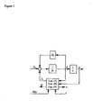
Figure 1 represents the physical construction of an idealised three-phase round-rotor synchronous generator with a single pair of poles per phase; -
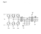
Figure 2 is a circuit diagram of an inverter for use in implementing the present invention; -
Figure 3 is a block diagram representation of a virtual synchronous generator, without control logic; -
Figure 4 corresponds toFigure 3 but includes control logic; -
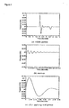
Figures 5a to c arc graphs of frequency variation over time in a simulation of an SSG according to the present invention; -
Figures 6 a and b arc graphs of real and reactive power respectively in the simulation; -
Figure 7a shows variation of the amplitude of the terminal voltage of the SSG during simulation, andFigure 7b shows, over a much briefer period of time, the sinusoidal variation of the three AC phases of the output from the SSG in a steady state; and -
Figures 8a to c are graphs of (a) frequency, (b) real and reactive power and (c) terminal voltage amplitude, all over time and all obtained in a second simulation of the SSG, this time in island mode. - The rest of this description is organised as follows. In Section I, a dynamic model of a synchronous generator is established under no assumptions on the signals. Although the model of an SG has been well described in the literature, the way the model is described here is somewhat fresh. Then, how to implement an inverter to mimic a synchronous generator is described in Section II and a system embodying the present invention for control of an SSG, incorporating frequency and voltage drooping mechanisms for load sharing, is described in Section III, followed by simulation results given in Section IV.
- The present embodiment of the invention is based on a mathematical model of a synchronous generator which is considered to be a dynamic system without any assumptions on the signals. Consider the
generator arrangement 10 seen inFigure 1 , which is a round rotor machine (without damping windings), with p pairs of poles per phase and no saturation effects in the iron core. - Three identical stator windings 12a-c arc distributed in slots around the periphery of a uniform air gap. The stator windings can be regarded as concentrated coils having self-inductance L and mutual inductance -M (M > 0 with a typical value ½L, the negative sign being due to the


- The flux linkages of the windings are


where ia, ib and ic are the stator phase currents and if is the rotor excitation current, i.e. the current through the rotor winding 14. Denote
and
- Assume for the moment that the neutral line is not connected, then

- The stator flux linkages can be rewritten as

where Ls = L + M, and the field flux linkage can be rewritten
where <., .> denotes the conventional inner product. The second term Mf <i, cos̃θ) is constant if the three phase currents are sinusoidal and balanced. Assume that the resistance of the stator windings is Rs, then the phase terminal voltages v = [va vb vc ] T can be obtained from (1) as
where e = [eu cb cc ] T is the back cmf due to the rotor movement given by
- We mention that, from (2), the field terminal voltage

where Rf is the resistance of the rotor winding. However, in the present treatment we shall not need the expression for vf because we shall use if , instead of vf , as an adjustable constant input. In other embodiments it would be possible to regulate vf in place of if . This completes modelling the electrical part of the machine. - The mechanical part of the machine is governed by

where J is the moment of inertia of all parts rotating with the rotor, Tm is the mechanical torque upon the rotor due to the driver acting upon it (e.g. the engine driving a power station generator), Te is the electromagnetic torque on the rotor due to its interaction with the stators and Dp is a damping factor. Te can be found from the total energy E stored in the machine, which is the sum of the magnetic energy stored in the stator and rotor magnetic fields and the kinetic energy stored in the rotating parts, i.e.
- Since the mechanical rotor position θm satisfies θ=pθm we have

- Note that if


- The above analysis is based on the condition that the neutral line is not connected. If the neutral line is connected, then the sum of the three line currents is not 0. Assume

where iN is the current flowing through the neutral line. Then the formula for the stator flux linkages (1) becomes
and the phase terminal voltages (3) become
where e is given by (4). The other formulae are not affected. - ft is important to note that, in a physical synchronous generator, the provision of a neutral line apparently complicates the system analysis. However, in an SSG to be designed in the next section, M is a design parameter and can hence be chosen as 0. The physical meaning of this is that the mutual inductance M between stator windings is 0. In other words, there is no magnetic coupling between stator windings. This docs not happen in a physical synchronous generator but can be easily implemented in an SSG. In the rest of this paper, M is chosen as 0 and the model of a synchronous generator, consisting of equations (3), (4), (5), 6) and (7), will be used to operate an inverter.
- In this section, the details of how to implement an inverter as a static synchronous generator will be described. A simple DC/AC converter (inverter) used to convert the DC power supply VDC obtained from renewable/distributed energy sources into three-phase AC (va, vb, vc ) is shown in
Figure 2 . It consists of threephase legs 16a-c and a three-phase LC filter 18 which is used to suppress the switching noise. If the inverter is to be connected to the grid then a three-phase coupling inductor 20 and a circuit breaker 22 are needed to interface with the grid. The filtering capacitors C should be chosen such that the resonant frequency

phase legs 16a-c (insulated gate bipolar transistors 22 are shown in the figure but other types of switch could be substituted). - An SSG can be implemented according to the mathematical model developed in the previous section. As explained in detail later in this section, an SSG consists of a power part, i.e., the inverter shown in
Figure 2 , and an electronic part shown inFigure 3 . These two parts are interfaced via the signals e and i (and v and vg to be used for regulating purposes). - It is advantageous (but not essential) to assume that the field (rotor) winding is fed by an adjustable DC current source if instead of a voltage source vf . In this case, the terminal voltage vf varies, but this is irrelevant. As long as if is constant, the generated voltage of the virtual generator from (4) is

- Define the generated real power P and reactive power Q as

where eq has the same amplitude as e but with a phase delayed from that of e by

- Then, the real power and reactive power are, respectively,


- Note that if


- These coincide with the conventional definitions for real power and reactive power (note that the
coefficient 3 is because there are three phases). When the voltage and current are in phase, i.e. when θ - φ = 0, the product of the rms values of the voltage and current gives the real power P. When the voltage and current are


Equation (6) can be written as
where the input is the mechanical torque Tm , while the electromagnetic torque Te depends on i and θ, according to (7). This equation, together with (7), (8) and (9), are implemented in the electronic part of an SSG shown inFigure 3 . Thus, the state variables of the SSG are i (which are actual currents), θ and θ̇ (which are a virtual angle and a virtual angular speed). The control inputs of the SSG are Tm and Mfif. In order to operate the SSG in a useful way, we need a controller that generates the signals Tm and Mfif such that system stability is maintained and the desired values of real and reactive power are followed. The significance of Q will be discussed in the next section. - The terminal voltages v = [va vb vc ] T given in (3) can be obtained from the (local load) terminals va , vb and vc of the inverter shown in
Figure 2 . The inductance Ls and resistance Rs of the inductor can be chosen to represent the stator impedance of a synchronous generator. The switches in the inverter are operated so that the average values of ea , eb and ec over a switching period should be equal to e given in (8) and, hence no special pulse-width-modulation (PWM) techniques are necessary. Also shown inFigure 2 is a three-phase interfacing inductor Lg /Rg and a circuit breaker to facilitate synchronisation/comection with the grid. - The terms "real" and "reactive" power arc very well known in relation to AC power transmission. The power flow resulting in net transfer of energy, over a complete AC cycle, is the real power. The power flow due to energy which is stored and returned to the source over a cycle (by virtue of capacitance, inductance or equivalent) is the reactive power.
- For synchronous generators, the rotor speed is maintained by the prime mover and it is known that the damping factor Dp is due to mechanical friction etc. In a real SG frequency tends to droop (fall) according to the real power delivered. This is important in the existing power distribution grid as it results in SGs sharing load. When the real power demand increases, the speed of the prime mover drops. The speed regulation system of the prime mover then increases the mechanical power, e.g. widening the throttle valve of an engine, so that a new power balance is achieved. This mechanism can be implemented by comparing the virtual angular speed θ̇ e.g. with an angular frequency reference θ̇,., e.g. the nominal angular speed θ̇n,, before feeding it into the damping block Dp - see the upper part of
Figure 4(a) . As a result, the damping factor Dp actually behaves as a frequency drooping coefficient, which is defined as the ratio of the required change of torque ΔT to the change of speed (frequency) Δ̇θ. That is
where Tmn is the nominal mechanical torque. Note that in much of the literature, - Dp is defined as


Figure 4(a) . Because of the built-in frequency drooping mechanism, an SSG automatically shares the load with other inverters of the same type connected on the same bus. The power regulation loop is very simple because no mechanical devices arc involved and no measurements are needed for real power regulation (all variables are available internally). - The regulation mechanism of the real power (torque) shown in the upper part of
Figure 4(a) has a cascaded control structure, of which the inner loop is the frequency loop and the outer loop is the real power (torque) loop. The time constant of the frequency loop is
- In other words, J can be chosen as

- Because there is no delay involved in the frequency drooping loop, the time constant τf can be made much smaller than that of a physical synchronous generator. In order to make sure that the frequency loop has a quick response so that it can track the frequency reference quickly, τf should be made small. Hence, for a given frequency drooping coefficient Dp, J should be made small. This indicates that it is not necessary to have a large inertia for the virtual physical synchronous generator, although a larger inertia means that more energy can be stored. In other words, the energy storage function of an SSG can, and should, be decoupled from the inertia.
- The regulation of reactive power Q flowing out of the SSG can be realised similarly. Define the voltage drooping coefficient Dq as the ratio of the required change of reactive power ΔQ to the change of voltage Δv, i.e.

where Qn is the nominal reactive power, which can be chosen as the nominal power, and vn is the nominal amplitude of terminal voltage v. The regulation mechanism for the reactive power can be realised as shown in the lower part ofFigure 4(a) . The difference between the voltage reference vr , e.g. the amplitude vn of the nominal voltage, and the amplitude vm of the actual terminal voltage v is amplified by the voltage drooping coefficient Dq before adding to the difference between the set point Qset and the current reactive power Q, which is calculated according to (9). The resulting signal is then fed into an integrator with a gain
- The regulation mechanism of the reactive power shown in the lower part of
Figure 4(a) has a cascaded control structure, if the effect of the LC filter 18 is ignored or compensated (which means v = e). The inner loop is the (amplitude) voltage loop and the outer loop is the reactive power loop. The time constant of the voltage loop is
as the variation of θ̇ is very small. Hence, K can be chosen as
- The amplitude vm of the terminal voltage v can be obtained as follows. Assume that va = vam sinθ a , vb = vbm sinθ b and vc = vcm snθ c , then

- When the terminal voltages are balanced, i.e., when vam = Vbm =vcm = Vm and


and the amplitude vm of the actual terminal voltage v can be obtained as
- In real implementation, a low-pass filter is needed to filter out the ripples at the doubled frequency as the terminal voltages may be unbalanced. This also applies to Te and Q.
- As shown above, an SSG can be operated in the same way as a synchronous generator under normal working conditions. An important process related to an SSG or SG is the synchronisation procedure, prior to connection of the SSG/SG to another SSG/SG or to the public grid. This procedure involves bringing the terminal voltage v to be (almost) the same as the grid voltage vg on the other side of the circuit breaker 22, which means the same amplitude, the same frequency and the same phase angle. It is not an easy task to implement this for conventional SGs as this procedure involves much external equipment. For the SSG developed in this paper, this is relatively easy as the variables required are all available internally. A change of operation mode from island mode (in which the SSG operates without connection to a power grid) to grid-connected mode or vice verse can be implemented via a controller multi-pole-double-throw (MPDT)
switch 30a, b,Figure 4 , with one throw for island mode (labelled as i) and the other for grid-connected mode (labelled as g), to change the frequency/voltage references. Whether an SSG works in island mode or grid-connected mode, the status of theMPDT switch 30a, b, is determined by the presence of the grid voltage and the status of a mode switch which sets the operation mode of the SSG. See Table 1 for the logic of operation. The default position of the mode switch is at "grid-connected" and it is turned to "island" when there is a fault. In grid-connected mode, the frequency/voltage references arc set as the corresponding values of the grid voltage vg and the integrator that produces phase θ, the electrical angle between the rotor field and the phase-a field, is reset according to the grid phase when the circuit breaker is not turned on. There are many ways to obtain the grid frequency θ̇ g and phase θ g ; one of them is to use a phase-locked loop (PLL), as shown at 32 inFigure 4 . The amplitude vgm of the voltage vg on the grid side of the circuit breaker can be calculated according to (10), replacing v with vg. In island mode, the references are set to the corresponding nominal values
- When the voltage across the circuit breaker is small, the SSG can provide a green (go-ahead) signal for the operator to turn on the circuit breaker (it can be set to turn on automatically). The circuit breaker is allowed to be turned on in two cases: (1) when the MPDT switch i_g is set at Throw g, i.e., when the grid voltage is present and the mode switch is turned at grid-connected mode; (2) when the grid voltage is not present and the mode switch is turned at island mode, which allows parallel operation of multiple inverters (to be discussed in more detail later).
- After the circuit breaker is turned on, as the amplitude of the terminal voltage is set to follow that of the grid voltage, the voltage drooping mechanism disappears and the terminal voltage amplitude is determined by the grid. The frequency also
Table I THE LOGIC OF OPERATION FOR AN SSG (TRUTH TABLE) Inputs Outputs Presence of vg Mode switch MPDT i_g Circuit breaker to be turned on Yes island i Prohibited Yes grid-connected g Allowed after synchronisation No island i Allowed without synchronisation No grid-connected i Prohibited - If there is no grid voltage present, then an SSG works in island mode and the real power and reactive power delivered by the SSG are determined by the load. If there is more than one SSG to be connected in parallel, then the first one that is put into operation works with the mode switch set at "island" to establish the system ficquency and voltage. Note that in this case the circuit breaker can be turned on straightaway, according to the logic of operation set in Table 1, so that the voltage is present on the other side of the circuit breaker, which allows other SSGs to synchronise with it and to join the system under the grid-connected mode. In this case, Pset and Qset should be set at 0 as the power delivered is determined by the local load.
- It is necessary to measure the terminal voltage v for the voltage drooping, the current i flowing out of the inverter for the calculation of Te P and Q the grid voltage vg for synchronisation. A complete SSG consists of a power part shown in
Figure 2 , and a complete electronic part shown inFigures 4(a) and (b) , which are interfaced with each other via θ̇r, θy and vr . It can be seen that the nominal angular frequency θn and voltage (amplitude) vn are all set in the system via the frequency reference θ̇r and voltage reference vr . A resetting mechanism is added to the integrator generating θ to prevent numerical overflow under normal working condition and to obtain the same phase as the grid voltage during synchronisation. The phase of the SSG can be reset as 0 when the grid voltage crosses 0, which is impossible for a physical synchronous generator. Another important mechanism is to add a constant phase shift θc to the phase θ so that the delay in the PWM switching process and the phase shift of the LC filter can be compensated, which brings the phase difference between v and vg to be minimal during synchronisation. The electronic part of an SSG can be implemented in a microcontroller (this is normally the case) and, hence, it is possible to use different values of Dv (Dq )and J (K) when the SSG works in different modes. - Some guidelines on choosing Dp and J are: (1) Dp should be chosen to satisfy the frequency regulation requirement; (2) J should be chosen to achieve the desired frequency-loop time constant τf.
- Some guidelines on choosing Dq and K are: (1) Dq should be chosen to satisfy the voltage regulation requirement; (2) K should be chosen to achieve the desired voltage-loop time constant τv.
- For relatively small inverters, Dp and (Dq) should be chosen so that the full step change of real and reactive power should not cause noticeable change in the frequency and voltage.
Table II PARAMETERS OF THE INVERTER-INFINITE BUS SYSTEM Parameters Values Parameters Values Ls 0.15 mII Lg 0.0534 mH Rs 0.045 Ω Rg 0.06 Ω C 22 µF Frequency 50 Hz R (parallel to C) 1000 Ω Voltage (line-line) 17 Vrms Rated power 100 W Initial grid phase 0° Inertia J 0.01 Kgm2 K 13580 - The idea described above has been verified with simulations. The parameters of the inverter for carrying out the simulations arc given in Table II.
- The frequency drooping coefficient is chosen as Dp = 0.2432 so that the frequency drops 0.5% when the torque (power) increases 100%. The virtual inertia is chosen as J=0.01 so that no-load time constant is roughly τf=0.04 second. The simulation was carried out in MATLAB® 7.4 with Simulink™. The solver used in the simulations is ode23tb with a
relative tolerance 10-3 and a maximum step size of 10-4 second. - The inverter is connected to the grid via a circuit breaker and a step-up transformer. In this case, Dq = 0. The SSG was connected to the grid at t=1 second. The real power P=80W was applied at t=2 second by suitably setting Pset and the reactive power Q=60 Var was applied at t=3.5 second by means of Qset. In the simulations, a model of the LC filter and the interfacing inductor was included in the control algorithm so that it is possible to assume that the inverter was connected to the grid virtually inside the controller all the time (although the converter was not connected to the grid physically until t=1 second). The initial state of 0̇ was set at 100π. The drooping coefficient Dp was reduced to 1% of its original value before any real power was applied and the inertia was reduced so that the no-load time constant WAS about 2 cycles before the inverter was connected to the grid.
- The response of the SSG frequency is shown in
Figure 5 . The SSG quickly synchronised with the grid in about 10 cycles. No visible dynamics were seen after the SSG was connected to the grid at t=1 second. When the SSG was requested to deliver 80W real power to the grid, the frequency of the SSG increased and then returned to the grid frequency 50Hz after about 20 cycles. When the SSG was requested to deliver 60Var reactive power to the grid, the frequency of the SSG decreased slightly and then returned to the grid frequency quickly. - The output power of the SSG is shown in
Figure 6 . During the synchronisation period, there were some oscillations in the power (which is inside the controller as the breaker is not yet turned on and hence it does not cause any problem). Before the SSG was requested to deliver power (i.e., before t=2 seconds), the real power and reactive power were zero. Then, the real power delivered to the grid gradually increased to the set point 80W. During this transient process, the SSG initially took reactive power from the grid but returned to normal. At t=3.5 second, the reactive power delivered by the SSG increased to the sctpoint 60Var gradually. During this period, the real power increased slightly but then returned to the set point 80W very quickly. - In this case, Pset and Qset were set at 0 and Dq =144.0876 so that the
voltage changes 5% if thereactive power changes 100%. The island mode is simulated by setting Rg =10000Ω and Lg =O. The resistor R connected in parallel with C is reduced to 5Ω at t=2 second and C is increased to 660µF at t=3.5 second. The current i is not fed back to the system before t=0.1 second, i.e., before the voltage v is established. - The frequency curve is shown in
Figure 8(a) . After the real power applied at t=2 second, the frequency reduced to 49.855Hz, which further reduced to 49.842Hz after the reactive load was applied. The real power and reactive power are shown inFigure 8(b) . The change of the load caused some fast oscillations (spikes) in the curve. The amplitude of the terminal voltage is shown inFigure 8(c) . Although there were some fast oscillations (spikes) in the voltage when the load was changed, the voltage fell into the close range of the nominal value very quickly.
Claims (15)
- A control device for an inverter, the control device implementing a model of a synchronous generator, wherein said inverter is controlled based on parameters calculated using said model so as to behave like a conventional synchronous generator, wherein said model comprising:variables representing the angular position and rotational speed of a virtual generator rotor,logic for calculating a virtual electromagnetic torque acting on the virtual generator rotor from measured inverter output current and from a variable representing a virtual excitation current,logic for calculating the rotational speed of the virtual rotor from the virtual electromagnetic torque and from at least one variable representing a virtual drive torque applied to the virtual generator rotor, and from a parameter J representing the rotor's virtual inertia wherein the moment of inertia J is chosen as the product of the time constant τg of a frequencey drooping loop and a damping factor Dp that behaves as a frequency drooping coefficient, andlogic for calculating, from the variables representing angular position and rotational speed of the virtual generator rotor and from the variable representing the excitation current, a control signal for controlling the inverter to produce an AC output which corresponds to that of the virtual synchronous generator,the control device further comprising logic which implements a first feedback loop in which deviation of the rotational speed of the virtual generator rotor from a reference rotational speed is detected and used to adjust the virtual drive torque, thereby to regulate the angular speed of the virtual generator rotor, and hence to regulate frequency of the AC output from the inverter and the real power supplied by the inverter.
- A control device as claimed in claim 1, further comprising logic implementing a second feedback loop in which deviation of a measured inverter output voltage from a reference value is detected and used in adjustment of the virtual excitation current, thereby to regulate the inverter output voltage.
- A control device as claimed in claim 2, in which the deviation of reactive power from a reference level is detected and is used in adjustment of the virtual excitation current in the second feedback loop, thereby to regulate reactive power supplied by the inverter.
- A control device as claimed in claim 1, in which the first feedback loop receives as an input a nominal virtual drive torque, this being added to a correction to the virtual drive torque provided through the feedback loop to form the virtual drive torque and added to the virtual electromagnetic torque to determine the total virtual torque acting upon the virtual generator rotor.
- A control device as claimed in claim 4, in which the total virtual torque acting upon the virtual rotor is integrated and divided by a virtual rotor momentum to determine the rotational speed of the virtual generator rotor.
- A control device as claimed in claim 5, in which the difference between the rotational speed of the virtual generator rotor and a reference rotational speed, corresponding to the desired AC output frequency of the inverter, is multiplied by a frequency drooping coefficient to form the correction to the virtual drive torque.
- A control device as claimed in claim 4, in which the nominal virtual drive torque is determined by dividing an input representing desired inverter real output power by a value representing the angular speed of the AC inverter output.
- A control device as claimed in claim 1, in which the virtual electromagnetic torque is calculated as the product of the measured inverter output current, the virtual excitation current, and a sin or cosine function of the angular position of the virtual generator rotor.
- A control device as claimed in claim 1, in which the inverter is controlled to provide an alternating output voltage determined from the model of the synchronous generator.
- A control device as claimed in claim 9, in which the alternating output voltage to be provided by the inverter is calculated as the product of the rotational speed of the virtual generator rotor, the virtual excitation current, and a sine or cosine function of the angular position of the virtual generator rotor.
- A control device as claimed in claim 10, in which the control signal for controlling the inverter is pulse width modulated to cause the inverter to provide the calculated alternating output voltage.
- A control device as claimed in claim 2, in which, in the second feedback loop, the difference between reactive power and its reference level is added to a voltage drooping variable representing the deviation of the measured inverter output voltage from its reference value and is integrated to establish the virtual excitation current.
- A method of controlling an inverter, comprising modelling of a synchronous generator to yield a model , wherein said inverter is controlled based on parameters calculated using said model so as to behave like a conventional sychronous generator, wherein said model is modelled by:representing the angular position and rotational speed of a virtual generator rotor using numerical variables,measuring the inverter's output current,calculating a virtual electromagnetic torque acting on the virtual generator rotor from measured inverter output current and from a variable representing a virtual excitation current,calculating the rotational speed of the virtual rotor from the virtual electromagnetic torque and from at least one variable representing a virtual drive torque applied to the virtual generator rotor, and from a parameter J representing the rotor's virtual inertia, wherein the moment of inertia J is chosen as the product of the time constant τg of a frequencey drooping loop and a damping factor Dp that behaves as a frequency drooping coefficient, andcalculating, from the variables representing angular position and rotational speed of the virtual generator rotor and from the variable representing the excitation current, a control signal for controlling the inverter to produce an AC output which corresponds to that of the virtual synchronous generator,implementing a first feedback loop in which deviation of the rotational speed of the virtual generator rotor from a reference rotational speed is detected and used to adjust the virtual drive torque, thereby to regulate the rotational speed of the virtual generator rotor, and hence to regulate frequency of the AC output from the inverter and the real power supplied by the inverter.
- A method as claimed in claim 13 further comprising implementing a second feedback loop in which deviation of a measured inverter output voltage from a reference value is detected and used in adjustment of the virtual excitation current, thereby to regulate the inverter output voltage.
- A method as claimed in claim 13 in which the deviation of reactive power from a reference level is detected and is used in adjustment of the virtual excitation current in the second feedback loop, thereby to regulate reactive power supplied by the inverter.
Applications Claiming Priority (2)
| Application Number | Priority Date | Filing Date | Title |
|---|---|---|---|
| GBGB0820699.7A GB0820699D0 (en) | 2008-11-12 | 2008-11-12 | Static synchronous generators |
| PCT/GB2009/051460 WO2010055322A2 (en) | 2008-11-12 | 2009-10-29 | Static synchronous generators |
Publications (2)
| Publication Number | Publication Date |
|---|---|
| EP2377238A2 EP2377238A2 (en) | 2011-10-19 |
| EP2377238B1 true EP2377238B1 (en) | 2015-07-08 |
Family
ID=40139800
Family Applications (1)
| Application Number | Title | Priority Date | Filing Date |
|---|---|---|---|
| EP09756165.8A Active EP2377238B1 (en) | 2008-11-12 | 2009-10-29 | Static synchronous generators |
Country Status (6)
| Country | Link |
|---|---|
| US (1) | US8880236B2 (en) |
| EP (1) | EP2377238B1 (en) |
| CN (1) | CN102257720B (en) |
| ES (1) | ES2548786T3 (en) |
| GB (1) | GB0820699D0 (en) |
| WO (1) | WO2010055322A2 (en) |
Families Citing this family (52)
| Publication number | Priority date | Publication date | Assignee | Title |
|---|---|---|---|---|
| EP2529462B1 (en) | 2010-01-26 | 2016-12-28 | Vestas Wind Systems A/S | Method for emulation of synchronous machine |
| CN102332718B (en) * | 2010-06-23 | 2015-05-13 | 维斯塔斯风力系统有限公司 | Method of operating a wind turbine, controller usable for operating a wind turbine, and wind turbine |
| ES2402467B1 (en) * | 2011-02-28 | 2014-01-27 | Abengoa Solar New Technologies S.A. | SYNCHRONOUS POWER CONTROLLER OF A GENERATION SYSTEM BASED ON STATIC POWER CONVERTERS. |
| ES2402465B1 (en) | 2011-02-28 | 2014-01-27 | Abengoa Solar New Technologies S.A. | VIRTUAL ADMITTANCE CONTROLLER BASED ON STATIC POWER CONVERTERS. |
| ES2402499B1 (en) | 2011-02-28 | 2013-11-26 | Abengoa Solar New Technologies S.A. | VIRTUAL ELECTROMECHANICAL CHARACTERISTICS CONTROLLER FOR STATIC POWER CONVERTERS. |
| CN102157937B (en) * | 2011-04-08 | 2013-04-17 | 华北电力大学 | Inverse system-based active and reactive power independent control method for microgrid |
| JP2013162623A (en) * | 2012-02-03 | 2013-08-19 | Toshiba Corp | Power supply system |
| JP5953077B2 (en) * | 2012-03-13 | 2016-07-13 | 東芝三菱電機産業システム株式会社 | Inverter test equipment |
| JP6084863B2 (en) * | 2013-02-28 | 2017-02-22 | 川崎重工業株式会社 | Power converter for grid connection |
| JP6386718B2 (en) * | 2013-11-20 | 2018-09-05 | 川崎重工業株式会社 | Power converter |
| CN103972928B (en) * | 2014-04-18 | 2016-05-25 | 国家电网公司 | The micro-operated control method of a kind of microgrid based on virtual synchronous generator |
| CN104734598B (en) * | 2015-03-31 | 2017-08-15 | 西安交通大学 | Based on band logical Damping voltage type current transformer virtual synchronous motor control method |
| CN104953617B (en) * | 2015-06-17 | 2017-08-11 | 清华大学 | Virtual synchronous generator bringing onto load grid-connected control method and system |
| CN105186554B (en) * | 2015-08-14 | 2017-09-29 | 许继集团有限公司 | The virtual synchronous generator method for becoming excellent certainly with rotary inertia and damping |
| CN105281596B (en) * | 2015-10-30 | 2018-01-23 | 清华大学 | The electronics commutation control system and control method of variable capacitance electrostatic motor |
| CN105743130B (en) * | 2016-03-22 | 2018-03-02 | 西安交通大学 | The method for improving virtual synchronous generator reactive power dynamic response performance |
| US9970417B2 (en) | 2016-04-14 | 2018-05-15 | General Electric Company | Wind converter control for weak grid |
| CN105915140A (en) * | 2016-04-22 | 2016-08-31 | 广东电网有限责任公司电力科学研究院 | Decoupling control method based on virtual synchronous generator and decoupling control device thereof |
| US10177574B2 (en) * | 2016-09-28 | 2019-01-08 | Nec Corporation | Dynamic frequency control scheme for microgrids using energy storage |
| CN106505617B (en) * | 2016-11-18 | 2019-02-22 | 国网青海省电力公司 | A kind of photovoltaic micro frequency recovery method and system |
| CN108242882B (en) * | 2016-12-27 | 2022-02-15 | 顺涞新能源环保科技(深圳)有限公司 | High magnetic energy AC/DC generator with multiple groups of series-connected generating mechanisms |
| JP6809753B2 (en) * | 2016-12-28 | 2021-01-06 | 川崎重工業株式会社 | Combined cycle system |
| CN106655272B (en) * | 2017-01-16 | 2018-12-04 | 湖南大学 | Inhibit failure temporary impact current mode virtual synchronous inverter and its control method |
| EP3872949A1 (en) | 2017-03-14 | 2021-09-01 | ABB Schweiz AG | Method and control system for controlling a power converter |
| GB2563086B (en) | 2017-06-04 | 2020-09-16 | Zhong Qingchang | Cyber Synchronous Machine (in short, Cybersync Machine) |
| CN107196344B (en) * | 2017-06-06 | 2020-05-05 | 湖南大学 | Self-synchronizing virtual synchronous inverter grid-connected controller and method with local load based on SPF-PLL |
| DE102017112936A1 (en) | 2017-06-13 | 2018-12-13 | Wobben Properties Gmbh | Method for feeding electrical power by means of a converter-controlled generating unit, in particular wind energy plant |
| CN107612043B (en) * | 2017-09-18 | 2020-03-17 | 西安交通大学 | Virtual synchronous generator control method based on phase feedforward |
| CN107565604B (en) * | 2017-10-25 | 2020-05-19 | 合肥工业大学 | Power distribution and parameter self-adaptive control method for multi-machine parallel virtual synchronous generator |
| JP7052290B2 (en) * | 2017-10-27 | 2022-04-12 | 東京電力ホールディングス株式会社 | AC / DC converter controller |
| GB2570151B (en) * | 2018-01-14 | 2020-07-15 | Zhong Qingchang | Reconfiguration of inertia, damping, and fault ride-through for a virtual synchronous machine |
| CN108363007B (en) * | 2018-02-27 | 2024-03-29 | 华北电力科学研究院有限责任公司 | Photovoltaic virtual synchronous generator performance testing device and method |
| JP7025973B2 (en) * | 2018-03-28 | 2022-02-25 | 株式会社日立製作所 | Distributed generation controller |
| CN108462206B (en) * | 2018-03-30 | 2020-01-10 | 华北电力科学研究院有限责任公司 | Method and device for determining selectable range of virtual inertia and damping coefficient of VSG |
| CN108599264B (en) * | 2018-05-10 | 2020-11-06 | 上海交通大学 | Virtual synchronous generator control-based frequency-voltage difference-free adjusting method |
| GB2574645B (en) * | 2018-06-14 | 2020-07-15 | Zhong Qingchang | Passive virtual synchronous machine with bounded frequency and virtual flux |
| CN108923454B (en) * | 2018-06-29 | 2022-09-02 | 中国电力科学研究院有限公司 | Control method and device for load virtual synchronous machine with voltage droop on direct current side |
| CN109193810B (en) * | 2018-09-06 | 2022-04-12 | 易事特集团股份有限公司 | Synchronous inverter control method, device and system |
| EP3647586A1 (en) * | 2018-10-29 | 2020-05-06 | GE Renewable Technologies | Method for starting a hydraulic turbine |
| CN113474989A (en) * | 2018-12-28 | 2021-10-01 | 维斯塔斯风力系统集团公司 | Wind turbine with virtual synchronous generator and DC link control |
| CN111835028A (en) * | 2019-04-15 | 2020-10-27 | 南京理工大学 | Microgrid inverter control method based on virtual synchronous generator |
| CN110112769B (en) * | 2019-04-16 | 2023-03-31 | 西安理工大学 | Output feedback self-adaptive control method for virtual synchronous machine |
| CN110739722B (en) * | 2019-10-24 | 2021-04-27 | 合肥工业大学 | Active standby variable inertia virtual synchronous control method for cascade inverter |
| CN110890765B (en) * | 2019-11-19 | 2021-04-02 | 山东大学 | Dynamic rotating speed protection method and system for virtual inertia frequency modulation of doubly-fed wind turbine |
| CN110957741A (en) * | 2019-12-30 | 2020-04-03 | 南京师范大学 | Reactive response control system for demand side back-to-back converter |
| JP6735039B1 (en) * | 2020-03-19 | 2020-08-05 | 富士電機株式会社 | Grid-connected inverter and grid frequency fluctuation suppression method |
| AU2021303781A1 (en) * | 2020-07-08 | 2023-02-16 | Ramot At Tel-Aviv University Ltd. | Virtual synchronous machines with improved voltage and frequency control |
| CN112271737B (en) * | 2020-07-30 | 2022-08-05 | 合肥工业大学 | Virtual synchronous machine strong power network stability control method based on inductive current differential feedback |
| CN112039131B (en) * | 2020-08-07 | 2022-01-25 | 国电南瑞南京控制系统有限公司 | Virtual synchronous machine-based dual-machine parallel system power distribution method and system |
| US11456645B2 (en) | 2020-12-10 | 2022-09-27 | General Electric Renovables Espana, S.L. | System and method for operating an asynchronous inverter-based resource as a virtual synchronous machine with storage |
| US11671039B2 (en) | 2020-12-10 | 2023-06-06 | General Electric Renovables Espana, S.L. | System and method for operating an asynchronous inverter-based resource as a virtual synchronous machine to provide grid-forming control thereof |
| CN114069697B (en) * | 2021-11-16 | 2023-11-17 | 福州大学 | Method for controlling inverter grid connection based on virtual synchronous generator principle |
Family Cites Families (19)
| Publication number | Priority date | Publication date | Assignee | Title |
|---|---|---|---|---|
| JP2948887B2 (en) * | 1990-09-07 | 1999-09-13 | 株式会社日立製作所 | Motor speed control device |
| JPH10122119A (en) * | 1996-10-22 | 1998-05-12 | Mitsubishi Electric Corp | Speed governing control device for water turbine and reversible pump-turbine and method thereof |
| DE10011929B4 (en) * | 2000-03-11 | 2004-07-01 | Wobben, Aloys, Dipl.-Ing. | synchronous generator |
| US7180263B2 (en) * | 2000-11-09 | 2007-02-20 | Daikin Industries, Ltd. | Synchronous motor control method and device |
| JP2002204597A (en) * | 2001-01-05 | 2002-07-19 | Honda Motor Co Ltd | Inverter-control type generator |
| DE10220122A1 (en) * | 2001-05-30 | 2002-12-19 | Continental Teves Ag & Co Ohg | Method and circuit arrangement for sensorless, electrical rotor position measurement of a permanently excited synchronous machine |
| US7680642B2 (en) * | 2005-01-12 | 2010-03-16 | The Japan Research Institute, Limited | Equivalent circuit for coil incorporated in circuit simulator, circuit simulator and method of preparation of same, and storage medium of circuit simulator program |
| CH697550B1 (en) * | 2005-03-30 | 2008-11-28 | Alstom Technology Ltd | Method for controlling a frequency converter. |
| US7339344B2 (en) * | 2005-08-25 | 2008-03-04 | International Rectifier Corporation | Self tuning method and apparatus for permanent magnet sensorless control |
| US7592761B2 (en) * | 2005-09-29 | 2009-09-22 | Agile Systems Inc. | System and method for starting and operating a motor |
| US20070069677A1 (en) * | 2005-09-29 | 2007-03-29 | Mackay David K | System and method for applying energy to a motor |
| US7279860B2 (en) * | 2005-09-29 | 2007-10-09 | Agile Systems Inc. | System and method for evaluating back electromotive force in a motor |
| US7477034B2 (en) * | 2005-09-29 | 2009-01-13 | Agile Systems Inc. | System and method for commutating a motor using back electromotive force signals |
| US7256564B2 (en) * | 2005-09-29 | 2007-08-14 | Agile Systems Inc. | System and method for attenuating noise associated with a back electromotive force signal in a motor |
| US7288911B2 (en) * | 2005-09-29 | 2007-10-30 | Agile Systems Inc. | System and method for commutating a motor |
| JP2007159368A (en) * | 2005-12-08 | 2007-06-21 | Toyota Motor Corp | Control unit of motor drive system |
| US7881814B2 (en) * | 2006-05-04 | 2011-02-01 | General Electric Company | Method and system for rapid modeling and verification of excitation systems for synchronous generators |
| JP4800839B2 (en) * | 2006-05-23 | 2011-10-26 | 株式会社デンソー | Excitation current control device for field winding type rotating electrical machine for vehicle |
| US7586286B2 (en) * | 2006-11-17 | 2009-09-08 | Continental Automotive Systems Us, Inc. | Method and apparatus for motor control |
-
2008
- 2008-11-12 GB GBGB0820699.7A patent/GB0820699D0/en active Pending
-
2009
- 2009-10-29 WO PCT/GB2009/051460 patent/WO2010055322A2/en active Application Filing
- 2009-10-29 CN CN200980151605.8A patent/CN102257720B/en active Active
- 2009-10-29 EP EP09756165.8A patent/EP2377238B1/en active Active
- 2009-10-29 ES ES09756165.8T patent/ES2548786T3/en active Active
- 2009-10-29 US US13/128,540 patent/US8880236B2/en active Active
Also Published As
| Publication number | Publication date |
|---|---|
| CN102257720A (en) | 2011-11-23 |
| WO2010055322A2 (en) | 2010-05-20 |
| CN102257720B (en) | 2014-09-10 |
| GB0820699D0 (en) | 2008-12-17 |
| US20110270463A1 (en) | 2011-11-03 |
| WO2010055322A3 (en) | 2010-07-22 |
| US8880236B2 (en) | 2014-11-04 |
| ES2548786T3 (en) | 2015-10-20 |
| EP2377238A2 (en) | 2011-10-19 |
Similar Documents
| Publication | Publication Date | Title |
|---|---|---|
| EP2377238B1 (en) | Static synchronous generators | |
| Zhong et al. | Synchronverters: Inverters that mimic synchronous generators | |
| Zhong et al. | Static synchronous generators for distributed generation and renewable energy | |
| Boudjema et al. | Fuzzy sliding mode control of a doubly fed induction generator for wind energy conversion | |
| Flannery et al. | Evaluation of voltage sag ride-through of a doubly fed induction generator wind turbine with series grid side converter | |
| Benkahla et al. | Comparative study of robust control strategies for a DFIG-based wind turbine | |
| Choudhury et al. | Performance analysis of doublyfed induction generator for wind energy conversion system | |
| Bekakra et al. | Comparison study between SVM and PWM inverter in sliding mode control of active and reactive power control of a DFIG for variable speed wind energy | |
| Shukla et al. | DC grid/bus tied DFIG based wind energy system | |
| Boudjema et al. | Robust control of a doubly fed induction generator (DFIG) fed by a direct AC-AC converter | |
| Williamson et al. | A controller for single-phase parallel inverters in a variable-head pico-hydropower off-grid network | |
| Shukla et al. | Instantaneous direct voltage and frequency control in DC grid tied DFIG based wind energy system | |
| Luna et al. | Control of DFIG-WT under unbalanced grid voltage conditions | |
| WO2014107802A1 (en) | Grid-connected induction machine with controllable power factor | |
| Rodriguez et al. | Grid-following and grid-forming PV and wind turbines | |
| Attuati et al. | Proportional-resonant stator current controller applied to seig based systems | |
| Singh et al. | Power control in centralized distributed AC load for wind energy system | |
| Sheeja et al. | Neural network theory based voltage and frequency controller for standalone wind energy conversion system | |
| Bouzid et al. | Voltage and frequency control of wind-powered islanded microgrids based on induction generator and STATCOM | |
| Ion et al. | Single-phase operation of an autonomous three-phase induction generator using a VSI-DL control system | |
| Naeem et al. | A robust auto-synchronizer for synchronverter | |
| Paul et al. | Constant frequency-unified power quality conditioner | |
| Hosseini et al. | Modelling of PSPP control system by using vector control principle and VSI | |
| CN116111867B (en) | Virtual instantaneous power-based grid-structured energy storage converter presynchronization control method | |
| Amorim et al. | Virtual Synchronous Generator with Harmonic Current Filtering Capability Based on Voltage Detection |
Legal Events
| Date | Code | Title | Description |
|---|---|---|---|
| PUAI | Public reference made under article 153(3) epc to a published international application that has entered the european phase |
Free format text: ORIGINAL CODE: 0009012 |
|
| 17P | Request for examination filed |
Effective date: 20110613 |
|
| AK | Designated contracting states |
Kind code of ref document: A2 Designated state(s): AT BE BG CH CY CZ DE DK EE ES FI FR GB GR HR HU IE IS IT LI LT LU LV MC MK MT NL NO PL PT RO SE SI SK SM TR |
|
| DAX | Request for extension of the european patent (deleted) | ||
| 17Q | First examination report despatched |
Effective date: 20131220 |
|
| GRAP | Despatch of communication of intention to grant a patent |
Free format text: ORIGINAL CODE: EPIDOSNIGR1 |
|
| INTG | Intention to grant announced |
Effective date: 20150206 |
|
| GRAS | Grant fee paid |
Free format text: ORIGINAL CODE: EPIDOSNIGR3 |
|
| GRAA | (expected) grant |
Free format text: ORIGINAL CODE: 0009210 |
|
| AK | Designated contracting states |
Kind code of ref document: B1 Designated state(s): AT BE BG CH CY CZ DE DK EE ES FI FR GB GR HR HU IE IS IT LI LT LU LV MC MK MT NL NO PL PT RO SE SI SK SM TR |
|
| REG | Reference to a national code |
Ref country code: GB Ref legal event code: FG4D |
|
| REG | Reference to a national code |
Ref country code: AT Ref legal event code: REF Ref document number: 736069 Country of ref document: AT Kind code of ref document: T Effective date: 20150715 Ref country code: CH Ref legal event code: EP |
|
| REG | Reference to a national code |
Ref country code: IE Ref legal event code: FG4D |
|
| REG | Reference to a national code |
Ref country code: DE Ref legal event code: R096 Ref document number: 602009032110 Country of ref document: DE |
|
| REG | Reference to a national code |
Ref country code: ES Ref legal event code: FG2A Ref document number: 2548786 Country of ref document: ES Kind code of ref document: T3 Effective date: 20151020 |
|
| REG | Reference to a national code |
Ref country code: FR Ref legal event code: PLFP Year of fee payment: 7 |
|
| REG | Reference to a national code |
Ref country code: AT Ref legal event code: MK05 Ref document number: 736069 Country of ref document: AT Kind code of ref document: T Effective date: 20150708 |
|
| REG | Reference to a national code |
Ref country code: NL Ref legal event code: MP Effective date: 20150708 |
|
| REG | Reference to a national code |
Ref country code: LT Ref legal event code: MG4D |
|
| PG25 | Lapsed in a contracting state [announced via postgrant information from national office to epo] |
Ref country code: LT Free format text: LAPSE BECAUSE OF FAILURE TO SUBMIT A TRANSLATION OF THE DESCRIPTION OR TO PAY THE FEE WITHIN THE PRESCRIBED TIME-LIMIT Effective date: 20150708 Ref country code: LV Free format text: LAPSE BECAUSE OF FAILURE TO SUBMIT A TRANSLATION OF THE DESCRIPTION OR TO PAY THE FEE WITHIN THE PRESCRIBED TIME-LIMIT Effective date: 20150708 Ref country code: GR Free format text: LAPSE BECAUSE OF FAILURE TO SUBMIT A TRANSLATION OF THE DESCRIPTION OR TO PAY THE FEE WITHIN THE PRESCRIBED TIME-LIMIT Effective date: 20151009 Ref country code: NO Free format text: LAPSE BECAUSE OF FAILURE TO SUBMIT A TRANSLATION OF THE DESCRIPTION OR TO PAY THE FEE WITHIN THE PRESCRIBED TIME-LIMIT Effective date: 20151008 Ref country code: FI Free format text: LAPSE BECAUSE OF FAILURE TO SUBMIT A TRANSLATION OF THE DESCRIPTION OR TO PAY THE FEE WITHIN THE PRESCRIBED TIME-LIMIT Effective date: 20150708 |
|
| PG25 | Lapsed in a contracting state [announced via postgrant information from national office to epo] |
Ref country code: SE Free format text: LAPSE BECAUSE OF FAILURE TO SUBMIT A TRANSLATION OF THE DESCRIPTION OR TO PAY THE FEE WITHIN THE PRESCRIBED TIME-LIMIT Effective date: 20150708 Ref country code: HR Free format text: LAPSE BECAUSE OF FAILURE TO SUBMIT A TRANSLATION OF THE DESCRIPTION OR TO PAY THE FEE WITHIN THE PRESCRIBED TIME-LIMIT Effective date: 20150708 Ref country code: AT Free format text: LAPSE BECAUSE OF FAILURE TO SUBMIT A TRANSLATION OF THE DESCRIPTION OR TO PAY THE FEE WITHIN THE PRESCRIBED TIME-LIMIT Effective date: 20150708 Ref country code: PT Free format text: LAPSE BECAUSE OF FAILURE TO SUBMIT A TRANSLATION OF THE DESCRIPTION OR TO PAY THE FEE WITHIN THE PRESCRIBED TIME-LIMIT Effective date: 20151109 Ref country code: PL Free format text: LAPSE BECAUSE OF FAILURE TO SUBMIT A TRANSLATION OF THE DESCRIPTION OR TO PAY THE FEE WITHIN THE PRESCRIBED TIME-LIMIT Effective date: 20150708 Ref country code: IS Free format text: LAPSE BECAUSE OF FAILURE TO SUBMIT A TRANSLATION OF THE DESCRIPTION OR TO PAY THE FEE WITHIN THE PRESCRIBED TIME-LIMIT Effective date: 20151108 |
|
| REG | Reference to a national code |
Ref country code: DE Ref legal event code: R097 Ref document number: 602009032110 Country of ref document: DE |
|
| PG25 | Lapsed in a contracting state [announced via postgrant information from national office to epo] |
Ref country code: EE Free format text: LAPSE BECAUSE OF FAILURE TO SUBMIT A TRANSLATION OF THE DESCRIPTION OR TO PAY THE FEE WITHIN THE PRESCRIBED TIME-LIMIT Effective date: 20150708 Ref country code: SK Free format text: LAPSE BECAUSE OF FAILURE TO SUBMIT A TRANSLATION OF THE DESCRIPTION OR TO PAY THE FEE WITHIN THE PRESCRIBED TIME-LIMIT Effective date: 20150708 Ref country code: DK Free format text: LAPSE BECAUSE OF FAILURE TO SUBMIT A TRANSLATION OF THE DESCRIPTION OR TO PAY THE FEE WITHIN THE PRESCRIBED TIME-LIMIT Effective date: 20150708 Ref country code: CZ Free format text: LAPSE BECAUSE OF FAILURE TO SUBMIT A TRANSLATION OF THE DESCRIPTION OR TO PAY THE FEE WITHIN THE PRESCRIBED TIME-LIMIT Effective date: 20150708 |
|
| PLBE | No opposition filed within time limit |
Free format text: ORIGINAL CODE: 0009261 |
|
| STAA | Information on the status of an ep patent application or granted ep patent |
Free format text: STATUS: NO OPPOSITION FILED WITHIN TIME LIMIT |
|
| PG25 | Lapsed in a contracting state [announced via postgrant information from national office to epo] |
Ref country code: LU Free format text: LAPSE BECAUSE OF FAILURE TO SUBMIT A TRANSLATION OF THE DESCRIPTION OR TO PAY THE FEE WITHIN THE PRESCRIBED TIME-LIMIT Effective date: 20151029 Ref country code: RO Free format text: LAPSE BECAUSE OF FAILURE TO SUBMIT A TRANSLATION OF THE DESCRIPTION OR TO PAY THE FEE WITHIN THE PRESCRIBED TIME-LIMIT Effective date: 20150708 |
|
| REG | Reference to a national code |
Ref country code: CH Ref legal event code: PL |
|
| 26N | No opposition filed |
Effective date: 20160411 |
|
| PG25 | Lapsed in a contracting state [announced via postgrant information from national office to epo] |
Ref country code: MC Free format text: LAPSE BECAUSE OF FAILURE TO SUBMIT A TRANSLATION OF THE DESCRIPTION OR TO PAY THE FEE WITHIN THE PRESCRIBED TIME-LIMIT Effective date: 20150708 |
|
| REG | Reference to a national code |
Ref country code: IE Ref legal event code: MM4A |
|
| PG25 | Lapsed in a contracting state [announced via postgrant information from national office to epo] |
Ref country code: LI Free format text: LAPSE BECAUSE OF NON-PAYMENT OF DUE FEES Effective date: 20151031 Ref country code: CH Free format text: LAPSE BECAUSE OF NON-PAYMENT OF DUE FEES Effective date: 20151031 |
|
| PG25 | Lapsed in a contracting state [announced via postgrant information from national office to epo] |
Ref country code: SI Free format text: LAPSE BECAUSE OF FAILURE TO SUBMIT A TRANSLATION OF THE DESCRIPTION OR TO PAY THE FEE WITHIN THE PRESCRIBED TIME-LIMIT Effective date: 20150708 |
|
| REG | Reference to a national code |
Ref country code: FR Ref legal event code: PLFP Year of fee payment: 8 |
|
| PG25 | Lapsed in a contracting state [announced via postgrant information from national office to epo] |
Ref country code: IE Free format text: LAPSE BECAUSE OF NON-PAYMENT OF DUE FEES Effective date: 20151029 |
|
| PG25 | Lapsed in a contracting state [announced via postgrant information from national office to epo] |
Ref country code: BE Free format text: LAPSE BECAUSE OF FAILURE TO SUBMIT A TRANSLATION OF THE DESCRIPTION OR TO PAY THE FEE WITHIN THE PRESCRIBED TIME-LIMIT Effective date: 20150708 |
|
| PG25 | Lapsed in a contracting state [announced via postgrant information from national office to epo] |
Ref country code: HU Free format text: LAPSE BECAUSE OF FAILURE TO SUBMIT A TRANSLATION OF THE DESCRIPTION OR TO PAY THE FEE WITHIN THE PRESCRIBED TIME-LIMIT; INVALID AB INITIO Effective date: 20091029 Ref country code: BG Free format text: LAPSE BECAUSE OF FAILURE TO SUBMIT A TRANSLATION OF THE DESCRIPTION OR TO PAY THE FEE WITHIN THE PRESCRIBED TIME-LIMIT Effective date: 20150708 Ref country code: SM Free format text: LAPSE BECAUSE OF FAILURE TO SUBMIT A TRANSLATION OF THE DESCRIPTION OR TO PAY THE FEE WITHIN THE PRESCRIBED TIME-LIMIT Effective date: 20150708 |
|
| PG25 | Lapsed in a contracting state [announced via postgrant information from national office to epo] |
Ref country code: CY Free format text: LAPSE BECAUSE OF FAILURE TO SUBMIT A TRANSLATION OF THE DESCRIPTION OR TO PAY THE FEE WITHIN THE PRESCRIBED TIME-LIMIT Effective date: 20150708 Ref country code: NL Free format text: LAPSE BECAUSE OF FAILURE TO SUBMIT A TRANSLATION OF THE DESCRIPTION OR TO PAY THE FEE WITHIN THE PRESCRIBED TIME-LIMIT Effective date: 20150708 |
|
| PG25 | Lapsed in a contracting state [announced via postgrant information from national office to epo] |
Ref country code: TR Free format text: LAPSE BECAUSE OF FAILURE TO SUBMIT A TRANSLATION OF THE DESCRIPTION OR TO PAY THE FEE WITHIN THE PRESCRIBED TIME-LIMIT Effective date: 20150708 Ref country code: MT Free format text: LAPSE BECAUSE OF FAILURE TO SUBMIT A TRANSLATION OF THE DESCRIPTION OR TO PAY THE FEE WITHIN THE PRESCRIBED TIME-LIMIT Effective date: 20150708 |
|
| REG | Reference to a national code |
Ref country code: FR Ref legal event code: PLFP Year of fee payment: 9 |
|
| PG25 | Lapsed in a contracting state [announced via postgrant information from national office to epo] |
Ref country code: MK Free format text: LAPSE BECAUSE OF FAILURE TO SUBMIT A TRANSLATION OF THE DESCRIPTION OR TO PAY THE FEE WITHIN THE PRESCRIBED TIME-LIMIT Effective date: 20150708 |
|
| REG | Reference to a national code |
Ref country code: FR Ref legal event code: PLFP Year of fee payment: 10 |
|
| P01 | Opt-out of the competence of the unified patent court (upc) registered |
Effective date: 20230529 |
|
| PGFP | Annual fee paid to national office [announced via postgrant information from national office to epo] |
Ref country code: GB Payment date: 20231020 Year of fee payment: 15 |
|
| PGFP | Annual fee paid to national office [announced via postgrant information from national office to epo] |
Ref country code: ES Payment date: 20231222 Year of fee payment: 15 |
|
| PGFP | Annual fee paid to national office [announced via postgrant information from national office to epo] |
Ref country code: IT Payment date: 20231026 Year of fee payment: 15 Ref country code: FR Payment date: 20231024 Year of fee payment: 15 Ref country code: DE Payment date: 20231020 Year of fee payment: 15 |