EP2377194B1 - Energiespeicher mit einer kühlvorrichtung - Google Patents
Energiespeicher mit einer kühlvorrichtung Download PDFInfo
- Publication number
- EP2377194B1 EP2377194B1 EP09765093.1A EP09765093A EP2377194B1 EP 2377194 B1 EP2377194 B1 EP 2377194B1 EP 09765093 A EP09765093 A EP 09765093A EP 2377194 B1 EP2377194 B1 EP 2377194B1
- Authority
- EP
- European Patent Office
- Prior art keywords
- cooling
- energy store
- cell
- cell body
- flat
- Prior art date
- Legal status (The legal status is an assumption and is not a legal conclusion. Google has not performed a legal analysis and makes no representation as to the accuracy of the status listed.)
- Active
Links
Images


Classifications
-
- H—ELECTRICITY
- H01—ELECTRIC ELEMENTS
- H01M—PROCESSES OR MEANS, e.g. BATTERIES, FOR THE DIRECT CONVERSION OF CHEMICAL ENERGY INTO ELECTRICAL ENERGY
- H01M10/00—Secondary cells; Manufacture thereof
- H01M10/04—Construction or manufacture in general
- H01M10/0413—Large-sized flat cells or batteries for motive or stationary systems with plate-like electrodes
-
- H—ELECTRICITY
- H01—ELECTRIC ELEMENTS
- H01M—PROCESSES OR MEANS, e.g. BATTERIES, FOR THE DIRECT CONVERSION OF CHEMICAL ENERGY INTO ELECTRICAL ENERGY
- H01M10/00—Secondary cells; Manufacture thereof
- H01M10/60—Heating or cooling; Temperature control
- H01M10/65—Means for temperature control structurally associated with the cells
- H01M10/655—Solid structures for heat exchange or heat conduction
- H01M10/6554—Rods or plates
- H01M10/6555—Rods or plates arranged between the cells
-
- H—ELECTRICITY
- H01—ELECTRIC ELEMENTS
- H01M—PROCESSES OR MEANS, e.g. BATTERIES, FOR THE DIRECT CONVERSION OF CHEMICAL ENERGY INTO ELECTRICAL ENERGY
- H01M10/00—Secondary cells; Manufacture thereof
- H01M10/60—Heating or cooling; Temperature control
- H01M10/61—Types of temperature control
- H01M10/613—Cooling or keeping cold
-
- H—ELECTRICITY
- H01—ELECTRIC ELEMENTS
- H01M—PROCESSES OR MEANS, e.g. BATTERIES, FOR THE DIRECT CONVERSION OF CHEMICAL ENERGY INTO ELECTRICAL ENERGY
- H01M10/00—Secondary cells; Manufacture thereof
- H01M10/60—Heating or cooling; Temperature control
- H01M10/62—Heating or cooling; Temperature control specially adapted for specific applications
- H01M10/625—Vehicles
-
- H—ELECTRICITY
- H01—ELECTRIC ELEMENTS
- H01M—PROCESSES OR MEANS, e.g. BATTERIES, FOR THE DIRECT CONVERSION OF CHEMICAL ENERGY INTO ELECTRICAL ENERGY
- H01M10/00—Secondary cells; Manufacture thereof
- H01M10/60—Heating or cooling; Temperature control
- H01M10/65—Means for temperature control structurally associated with the cells
- H01M10/655—Solid structures for heat exchange or heat conduction
- H01M10/6551—Surfaces specially adapted for heat dissipation or radiation, e.g. fins or coatings
-
- H—ELECTRICITY
- H01—ELECTRIC ELEMENTS
- H01M—PROCESSES OR MEANS, e.g. BATTERIES, FOR THE DIRECT CONVERSION OF CHEMICAL ENERGY INTO ELECTRICAL ENERGY
- H01M10/00—Secondary cells; Manufacture thereof
- H01M10/60—Heating or cooling; Temperature control
- H01M10/65—Means for temperature control structurally associated with the cells
- H01M10/655—Solid structures for heat exchange or heat conduction
- H01M10/6554—Rods or plates
-
- B—PERFORMING OPERATIONS; TRANSPORTING
- B60—VEHICLES IN GENERAL
- B60L—PROPULSION OF ELECTRICALLY-PROPELLED VEHICLES; SUPPLYING ELECTRIC POWER FOR AUXILIARY EQUIPMENT OF ELECTRICALLY-PROPELLED VEHICLES; ELECTRODYNAMIC BRAKE SYSTEMS FOR VEHICLES IN GENERAL; MAGNETIC SUSPENSION OR LEVITATION FOR VEHICLES; MONITORING OPERATING VARIABLES OF ELECTRICALLY-PROPELLED VEHICLES; ELECTRIC SAFETY DEVICES FOR ELECTRICALLY-PROPELLED VEHICLES
- B60L50/00—Electric propulsion with power supplied within the vehicle
- B60L50/50—Electric propulsion with power supplied within the vehicle using propulsion power supplied by batteries or fuel cells
- B60L50/60—Electric propulsion with power supplied within the vehicle using propulsion power supplied by batteries or fuel cells using power supplied by batteries
- B60L50/64—Constructional details of batteries specially adapted for electric vehicles
-
- B—PERFORMING OPERATIONS; TRANSPORTING
- B60—VEHICLES IN GENERAL
- B60L—PROPULSION OF ELECTRICALLY-PROPELLED VEHICLES; SUPPLYING ELECTRIC POWER FOR AUXILIARY EQUIPMENT OF ELECTRICALLY-PROPELLED VEHICLES; ELECTRODYNAMIC BRAKE SYSTEMS FOR VEHICLES IN GENERAL; MAGNETIC SUSPENSION OR LEVITATION FOR VEHICLES; MONITORING OPERATING VARIABLES OF ELECTRICALLY-PROPELLED VEHICLES; ELECTRIC SAFETY DEVICES FOR ELECTRICALLY-PROPELLED VEHICLES
- B60L58/00—Methods or circuit arrangements for monitoring or controlling batteries or fuel cells, specially adapted for electric vehicles
- B60L58/10—Methods or circuit arrangements for monitoring or controlling batteries or fuel cells, specially adapted for electric vehicles for monitoring or controlling batteries
- B60L58/24—Methods or circuit arrangements for monitoring or controlling batteries or fuel cells, specially adapted for electric vehicles for monitoring or controlling batteries for controlling the temperature of batteries
- B60L58/26—Methods or circuit arrangements for monitoring or controlling batteries or fuel cells, specially adapted for electric vehicles for monitoring or controlling batteries for controlling the temperature of batteries by cooling
-
- H—ELECTRICITY
- H01—ELECTRIC ELEMENTS
- H01M—PROCESSES OR MEANS, e.g. BATTERIES, FOR THE DIRECT CONVERSION OF CHEMICAL ENERGY INTO ELECTRICAL ENERGY
- H01M10/00—Secondary cells; Manufacture thereof
- H01M10/05—Accumulators with non-aqueous electrolyte
- H01M10/052—Li-accumulators
- H01M10/0525—Rocking-chair batteries, i.e. batteries with lithium insertion or intercalation in both electrodes; Lithium-ion batteries
-
- H—ELECTRICITY
- H01—ELECTRIC ELEMENTS
- H01M—PROCESSES OR MEANS, e.g. BATTERIES, FOR THE DIRECT CONVERSION OF CHEMICAL ENERGY INTO ELECTRICAL ENERGY
- H01M10/00—Secondary cells; Manufacture thereof
- H01M10/60—Heating or cooling; Temperature control
- H01M10/64—Heating or cooling; Temperature control characterised by the shape of the cells
- H01M10/647—Prismatic or flat cells, e.g. pouch cells
-
- H—ELECTRICITY
- H01—ELECTRIC ELEMENTS
- H01M—PROCESSES OR MEANS, e.g. BATTERIES, FOR THE DIRECT CONVERSION OF CHEMICAL ENERGY INTO ELECTRICAL ENERGY
- H01M10/00—Secondary cells; Manufacture thereof
- H01M10/60—Heating or cooling; Temperature control
- H01M10/65—Means for temperature control structurally associated with the cells
- H01M10/653—Means for temperature control structurally associated with the cells characterised by electrically insulating or thermally conductive materials
-
- H—ELECTRICITY
- H01—ELECTRIC ELEMENTS
- H01M—PROCESSES OR MEANS, e.g. BATTERIES, FOR THE DIRECT CONVERSION OF CHEMICAL ENERGY INTO ELECTRICAL ENERGY
- H01M2220/00—Batteries for particular applications
- H01M2220/20—Batteries in motive systems, e.g. vehicle, ship, plane
-
- Y—GENERAL TAGGING OF NEW TECHNOLOGICAL DEVELOPMENTS; GENERAL TAGGING OF CROSS-SECTIONAL TECHNOLOGIES SPANNING OVER SEVERAL SECTIONS OF THE IPC; TECHNICAL SUBJECTS COVERED BY FORMER USPC CROSS-REFERENCE ART COLLECTIONS [XRACs] AND DIGESTS
- Y02—TECHNOLOGIES OR APPLICATIONS FOR MITIGATION OR ADAPTATION AGAINST CLIMATE CHANGE
- Y02E—REDUCTION OF GREENHOUSE GAS [GHG] EMISSIONS, RELATED TO ENERGY GENERATION, TRANSMISSION OR DISTRIBUTION
- Y02E60/00—Enabling technologies; Technologies with a potential or indirect contribution to GHG emissions mitigation
- Y02E60/10—Energy storage using batteries
-
- Y—GENERAL TAGGING OF NEW TECHNOLOGICAL DEVELOPMENTS; GENERAL TAGGING OF CROSS-SECTIONAL TECHNOLOGIES SPANNING OVER SEVERAL SECTIONS OF THE IPC; TECHNICAL SUBJECTS COVERED BY FORMER USPC CROSS-REFERENCE ART COLLECTIONS [XRACs] AND DIGESTS
- Y02—TECHNOLOGIES OR APPLICATIONS FOR MITIGATION OR ADAPTATION AGAINST CLIMATE CHANGE
- Y02P—CLIMATE CHANGE MITIGATION TECHNOLOGIES IN THE PRODUCTION OR PROCESSING OF GOODS
- Y02P70/00—Climate change mitigation technologies in the production process for final industrial or consumer products
- Y02P70/50—Manufacturing or production processes characterised by the final manufactured product
-
- Y—GENERAL TAGGING OF NEW TECHNOLOGICAL DEVELOPMENTS; GENERAL TAGGING OF CROSS-SECTIONAL TECHNOLOGIES SPANNING OVER SEVERAL SECTIONS OF THE IPC; TECHNICAL SUBJECTS COVERED BY FORMER USPC CROSS-REFERENCE ART COLLECTIONS [XRACs] AND DIGESTS
- Y02—TECHNOLOGIES OR APPLICATIONS FOR MITIGATION OR ADAPTATION AGAINST CLIMATE CHANGE
- Y02T—CLIMATE CHANGE MITIGATION TECHNOLOGIES RELATED TO TRANSPORTATION
- Y02T10/00—Road transport of goods or passengers
- Y02T10/60—Other road transportation technologies with climate change mitigation effect
- Y02T10/70—Energy storage systems for electromobility, e.g. batteries
Definitions
- the invention relates to an energy storage device for storing electrical energy with a cooling device, in particular for a motor vehicle.
- Hybrid or electric vehicles are vehicles which, in principle, are driven in whole or in part by electrical energy.
- Hybrid-powered vehicles also called hybrid vehicles, have, for example, an internal combustion engine and an electric machine for generating the drive power. In a pure electric vehicle, the drive power is provided solely by an electric machine.
- Both vehicle types, hybrid and electric vehicles have in common that large amounts of electrical energy must be provided and transferred.
- the storage of electrical energy takes place in energy storage, especially batteries, which are usually composed of a plurality of individual cells.
- Such cells may be, for example, lithium-ion cells.
- a cell consists of the "actual" cell body (composite of conductor metal foils, electrode coatings and separator), the battery poles (tabs, tabs), which are usually welded to the arrester foil, and the packaging.
- the housing is sealed except for a small opening. Through the opening of the electrolyte is introduced before the cell or the cell body is finally closed.
- lithium-ion cells which are composed of an electrode stack or a "prismatic Jellyrole" are like film packaging made of a composite of thin plastic films and aluminum interlayers used. These have the advantage that less material is used compared to rigid metal housings.
- the volume and weight of the packaging are lower and this improves the energy or power density (W / L, Wh / L, W / kg, Wh / kg) of the cell.
- the film for packaging prismatic cells is often referred to as a coffee-bag, because a process similar to that used for packaging coffee is in the background: laminate films sealed under vacuum to keep the inner product water-free and compact and from loss of flavor (of the electrolyte).
- laminate films sealed under vacuum to keep the inner product water-free and compact and from loss of flavor (of the electrolyte).
- this is not a bag manufactured by bubble extrusion, but one of two parts welded together.
- the sealing seams can be found on the side, possibly also on the top and bottom.
- the seal width is 1mm per year life.
- FIG. 1 refers to a structure of a cooling device for a conventional energy storage ESP0 is shown. This consists in the dissipation of heat through a mounted on the flat side (or the base in prismatic cells) of the cells Z0 cooling plate KB.
- the cells have a direction-dependent different heat conduction. In the direction of the surface (XY), a high heat conduction can be found by the current conductors of aluminum and copper inside the cells. Perpendicular, in the direction of the surface normal, the heat conduction is significantly reduced. The electrode coating and the separator between the electrodes conduct the heat much less.
- the cells Z0 are respectively applied to the right and left of the cooling plate KB.
- a stable, thermally conductive and electrically insulating connection is realized by means of adhesive connection.
- the cooling plate KB assumes the function of heat conduction and stabilization of the cells Z0.
- the publication US 5,871,861 A shows an energy store for storing electrical energy with at least one cell having a cell body bounded by two parallel to a cell body plane bases, and by a first and a plurality of second perpendicular to the cell body plane extending side surfaces connecting the bases, and with a cooling device that dissipates heat from the cell via the first side surface.
- the publication WO 2008/106946 A2 discloses an energy storage cell with a flexible shell, which is attached flat to a heat conducting plate, wherein the heat conducting plate is thermally coupled to a tempering device for cooling and / or heating of the energy storage cell.
- the publication JP 2005 071784 A shows a battery consisting of a plurality of stacked cells, which are connected in series with each other, wherein a cooling element is attached to at least one of the cells.
- the object of the present invention is to provide an efficient way to create an energy storage, optimized by the heat conduction in the energy storage and heat accumulation can be prevented.
- an energy store for storing electrical energy comprises at least one flat cell (for storing electrical energy) with a flat cell body, which is delimited by two base areas running parallel to a cell body level, and by a first and several second ones perpendicular to the cell body Cell body level extending side surfaces that connect the base surfaces.
- the flat cell is designed in particular as a prismatic flat cell.
- the cell body may have a substantially prismatic shape.
- the energy storage device further has a cooling device with a cooling element that is thermally coupled to the first side surface in order to dissipate heat from the flat cell via this side surface. The coupling takes place in particular flat, in order to ensure a good heat dissipation.
- the heat is thus conducted from the cell bottom (realized by the first side surface) into the cooling element and from the cooling element into a cooling sink. This optimizes the heat conduction at a thermodynamically critical point and avoids the formation of hotspots (hot spots) on the cell floor under comparable conditions.
- the energy storage is particularly suitable for use in a motor vehicle.
- the energy storage device further comprises a heat-conductive connection layer, which is arranged between the first side surface and the cooling element.
- This thermally conductive compound layer can be a thermally conductive polyurethane foam (PU foam), a thermally conductive GAP filler, a thermal pad, a thermal grease, a thermally conductive foam, or a double-sided adhesive tape.
- PU foam thermally conductive polyurethane foam
- GAP filler a thermal pad
- thermal grease thermally conductive foam
- a double-sided adhesive tape a mechanical decoupling of the cell body from the cooling element can be achieved, in particular when using soft materials (PU foam, foam) as a heat-conducting connecting layer, whereby the operation of the flat cell improves and the life is increased.
- the cell body of the at least one flat cell it is conceivable for the cell body of the at least one flat cell to have a package surrounding the cell body, which has a connecting section projecting away from the cell body at least along the first side face.
- This connecting section is also referred to as a sealed seam and results in foil-packed flat cells, which are also known by the common name "coffee bags".
- the use of a heat-conducting connecting layer is advantageous.
- Particularly advantageous here is the use of soft materials as a heat-conducting compound layer to mechanically stress the sealed seams as little as possible.
- cooling element has at least one recess or a groove for receiving the connecting section protruding from the first side face.
- the cooling device further has a cooling plate, which is thermally coupled to one of the base surfaces of the at least one flat cell.
- the cooling plate can be used as a Cooling fin or a cooling plate may be formed.
- the cooling plate may be connected to the cooling element.
- a clamping, plug, rivet, screw or welded connection can be provided for a fixed connection of cooling element and cooling plate.
- the energy store has at least two flat cells which are each connected to the cooling plate at a base area and to the cooling element at the first side area.
- the respective flat cells can be lithium-ion cells, so that a lithium-ion energy storage is created.
- an energy storage arrangement is provided with an energy store mentioned above or its embodiments and a heat sink, which serves as a heat sink for the cooling element and optionally the cooling plate, and is connected to the cooling element and / or the cooling plate.
- the heat sink may be formed as a cooled with a coolant, such as water, hollow body.
- a motor vehicle is provided with an energy storage arrangement as mentioned above.
- the heat sink may be thermally connected to a vehicle-mounted cooling unit or be formed by this.
- an energy storage ESP1 for storing electrical energy has two prismatic flat cells Z1 and Z2 (for example lithium-ion cells), each with a (flat) cell body ZK, which is delimited by two bases G11, G12 and G21 running parallel to a cell body plane , G22 and by a first ZB (cell bottom) and several second ZD (here only the side surfaces at the upper portion of the cell called) perpendicular to the cell body plane ZE extending side surfaces that connect the bases.
- Z1 and Z2 for example lithium-ion cells
- a cooling device of the energy store ESP1 comprises a cooling element or a cooling foot KF which is thermally coupled to a respective cell bottom ZB in order to dissipate heat from the flat cells Z1 and Z2 via the cell bottom ZB. Furthermore, a heat-conducting connection layer WLM is provided, which is arranged between the respective cell bottom ZB and the cooling foot KF.
- the cooling foot KF has respective recesses KA for receiving sealing seams SN, which the flat cells have due to their foil packaging.
- the cooling device has a cooling plate in the form of a cooling plate KB, which is thermally coupled to one of the bases G12 and G21 of the flat cells Z1 and Z2.
- the cooling plate KB is firmly connected to the cooling foot KF.
- a heat sink KK serves as a heat sink for the cooling base KF and the cooling plate KB.
- the idea is that the dissipation of heat in addition to the cooling plate KB (cooling plate) via the cell bottom ZB (a first side surface) takes place.
- the cooling foot KF (as a cooling element), which via the heat-conductive connection (such as PU foam, GAP filler, thermo pad, thermal grease, thin foam, double-sided tape, etc.) WLM between the cell bottom and the cooling base the heat sink KK is connected.
- the heat-conductive connection such as PU foam, GAP filler, thermo pad, thermal grease, thin foam, double-sided tape, etc.
- a corresponding recess or a corresponding cavity KA is provided in the cooling foot.
- Cooling plates also referred to as cooling fins, often consist of two components, since the shape of fin and cooling foot is far outside the standard circle for die-cast aluminum.
- the heat is thus conducted from the cell bottom ZB into the cooling base KF and from the cooling base into the cooling body KK, without going through the cooling plate KB. This optimizes the heat conduction at a thermodynamically critical point and prevents the formation of hotspots on the underside of the cell under comparable conditions.
Landscapes
- Engineering & Computer Science (AREA)
- Manufacturing & Machinery (AREA)
- Chemical & Material Sciences (AREA)
- Chemical Kinetics & Catalysis (AREA)
- Electrochemistry (AREA)
- General Chemical & Material Sciences (AREA)
- Life Sciences & Earth Sciences (AREA)
- Sustainable Development (AREA)
- Sustainable Energy (AREA)
- Power Engineering (AREA)
- Transportation (AREA)
- Mechanical Engineering (AREA)
- Secondary Cells (AREA)
- Battery Mounting, Suspending (AREA)
- Electric Propulsion And Braking For Vehicles (AREA)
Description
- Die Erfindung betrifft einen Energiespeicher zur Speicherung von elektrischer Energie mit einer Kühlvorrichtung, insbesondere für ein Kraftfahrzeug.
- Als Hybrid- bzw. Elektrofahrzeuge bezeichnet man Fahrzeuge, die prinzipbedingt ganz oder teilweise durch elektrische Energie angetrieben werden. Kraftfahrzeuge mit Hybridantrieb, auch Hybridfahrzeuge genannt, haben zur Erzeugung der Antriebsleistung beispielsweise eine Verbrennungsmaschine und eine elektrische Maschine. Bei einem reinen Elektrofahrzeug wird die Antriebsleistung allein durch eine elektrische Maschine bereitgestellt. Beiden Fahrzeugtypen, Hybrid- und Elektrofahrzeug ist gemein, dass große Mengen elektrischer Energie bereitgestellt und transferiert werden müssen.
- Die Speicherung der elektrischen Energie erfolgt dabei in Energiespeichern, insbesondere Batterien, die meist aus einer Vielzahl von einzelnen Zellen aufgebaut sind. Derartige Zellen können beispielsweise Lithium-Ionen-Zellen sein. Eine Zelle besteht dabei aus dem "eigentlichen" Zellkörper (Verbund aus Ableitermetallfolien, Elektrodenbeschichtungen und Separator), den meist an die Ableiterfolie angeschweißten Batteriepolen (Fähnchen, Tabs) und der Verpackung. Das Gehäuse wird bis auf eine kleine Öffnung versiegelt. Durch die Öffnung wird der Elektrolyt eingebracht, bevor die Zelle bzw. der Zellkörper endgültig verschlossen wird. Für Lithium-Ionen-Zellen, die aus einem Elektrodenstapel oder einem "prismatischen Jellyrole" aufgebaut sind werden gerne Folienverpackung aus einem Verbund aus dünnen Kunststofffolien und Alu-Zwischen¬schichten verwendet. Diese haben im Vergleich zu starren Metallgehäusen den Vorteil, dass weniger Material verwendet wird. Volumen und Gewicht der Verpackung sind geringer und dadurch wird die Energie- oder Leistungsdichte (W/L, Wh/L, W/kg, Wh/kg) der Zelle verbessert. Die Folie für die Verpackung prismatischer Zellen wir häufig auch Coffee-Bag genannt, da ein ähnlicher Prozess wie für die Verpackung von Kaffee im Hintergrund steht: Laminatfolien die unter Vakuum versiegelt werden, um das innere Produkt wasserfrei und kompakt zu halten und vor Verlust des Aromas (des Elektrolyten) zu schützen. In aller Regel handelt es sich dabei nicht um eine durch Blasextrusion hergestellte Tüte, sondern um eine aus zwei miteinander verschweißten Teilen. Die Siegelnähte sind seitlich, eventuell auch oben und unten, zu finden. Als Faustregel für die Siegelnahtbreite gilt 1mm pro Jahr Lebensdauer. Für automobile Anwendungen mit Forderungen von 10 Jahre Lebensdauer, ergeben sich so Siegelnähte von bis zu 10mm. Sie werden üblicherweise seitlich gefaltet und an das Produkt angelegt, um zu große Volumenverluste zu vermeiden. Für einzelne Zellen kann auf diese Art tatsächlich das Todvolumen reduziert werden. Für Energiespeicher aus miteinander seriell oder parallel verschalteten Zellen hängt es von der Verbindungstechnologie ab, ob die seitliche Naht störend wirkt und Berücksichtigung im Energiespeicher- bzw. Batteriedesign finden muss.
- Wie bereits erwähnt sind in Energiespeichern für Kraftfahrzeuge hohe Leistungs- und/ oder Energiedichten je nach Funktion (Hybrid oder Elektrofahrzeug) auf geringem Bauraum notwendig. Diese Anforderungen werden unter anderem mit den schon erwähnten Lithium-Ionen-Energiespeichern realisiert. Dabei entsteht im Betrieb durch die hohen Lade- und Entladeströme in den Zellen des Energiespeichers Wärme. Für eine optimale Funktion und eine hohe Lebensdauer der Zellen muss die Wärme möglichst effizient und gleichmäßig über den Querschnitt der Zellen zu einer Kühlvorrichtung abgeführt werden.
- Es sei nun auf
Figur 1 verwiesen, in der ein Aufbau einer Kühlvorrichtung für einen herkömmlichen Energiespeicher ESP0 gezeigt ist. Diese besteht in der Ableitung der Wärme durch ein auf der flachen Seite (oder der Grundfläche bei prismatischen Zellen) der Zellen Z0 angebrachtes Kühlblech KB. Die Zellen weisen jedoch eine richtungsabhängige unterschiedliche Wärmeleitung auf. In Richtung der Fläche (X-Y) ist durch die im Inneren der Zellen befindliche Stromableiter aus Aluminium und Kupfer eine hohe Wärmeleitung zu finden. Senkrecht, in Richtung der Flächennormalen, ist die Wärmeleitung deutlich vermindert. Die Elektrodenbeschichtung und der Separator zwischen den Elektroden leiten die Wärme deutlich weniger. - Die Zellen Z0 sind jeweils rechts und links auf das Kühlblech KB aufgebracht. Dabei wird mittels Klebeverbindung eine stabile, thermisch leitende und elektrisch isolierende Verbindung realisiert. Das Kühlblech KB übernimmt dabei die Funktion der Wärmeleitung und Stabilisierung der Zellen Z0.
- Bei diesem herkömmliche Aufbau besteht auch in den Zellen ein Wärmefluss WF (gekennzeichnet durch die in den Zellen Z0 von oben nach unten verlaufenden Pfeile in Richtung eines mit dem Kühlblech KB verbundenen Kühlkörper KK), der zu einem Wärmestau WST am Zellboden ZB (Zellunterkannte ohne Siegelnaht) führt.
- Die Druckschrift
US 5 871 861 A zeigt einen Energiespeicher zur Speicherung elektrischer Energie mit zumindest einer Zelle mit einem Zellkörper, der begrenzt wird durch zwei zu einer Zellkörperebene parallel verlaufende Grundflächen, sowie durch eine erste und mehrere zweite senkrecht zur Zellkörperebene verlaufende Seitenflächen, die die Grundflächen verbinden, und mit einer Kühlvorrichtung, die über die erste Seitenfläche Wärme aus der Zelle abführt. - Die Druckschrift
WO 2008/106946 A2 offenbart eine Energiespeicherzelle mit einer flexiblen Hülle, die flächig an einer Wärmeleitplatte befestigt ist, wobei die Wärmeleitplatte thermisch an eine Temperiervorrichtung zum Kühlen und/oder Heizen der Energiespeicherzelle gekoppelt ist. - Die Druckschrift
JP 2005 071784 A - Die Aufgabe der vorliegenden Erfindung besteht nun darin, eine effiziente Möglichkeit zur Schaffung eines Energiespeichers anzugeben, durch die die Wärmeleitung im Energiespeicher optimiert und ein Wärmestau verhindert werden kann.
- Die Erfindung wird durch die unabhängigen Ansprüche gelöst. Vorteilhafte Ausgestaltungen der Erfindung sind Gegenstand der Unteransprüche.
- Gemäß einem ersten Aspekt der Erfindung umfasst ein Energiespeicher zur Speicherung von elektrischer Energie zumindest eine Flachzelle (zur Speicherung von elektrischer Energie) mit einem flachen Zellkörper, der begrenzt wird durch zwei zu einer Zellkörperebene parallel verlaufende Grundflächen, sowie durch eine erste und mehrere zweite senkrecht zur Zellkörperebene verlaufende Seitenflächen, die die Grundflächen verbinden. Die Flachzelle ist dabei insbesondere als eine prismatische Flachzelle ausgelegt. Hierbei kann der Zellkörper eine im Wesentlichen prismaförmige Gestalt haben. Der Energiespeicher hat ferner eine Kühlvorrichtung mit einem Kühlelement, das mit der ersten Seitenfläche thermisch gekoppelt ist, um über diese Seitenfläche Wärme aus der Flachzelle abzuführen. Die Kopplung erfolgt dabei insbesondere flächig, um eine gute Wärmeableitung zu gewährleisten. Die Wärme wird so vom Zellboden (realisiert durch die erste Seitenfläche) in das Kühlelement und vom Kühlelement in eine Kühlsenke geleitet. Dadurch wird die Wärmeleitung an einer thermodynamisch kritischen Stelle optimiert sowie die Entstehung von Hotspots (heiße Punkte) am Zellboden unter vergleichbaren Bedingungen vermieden.
- Der Energiespeicher ist dabei insbesondere für den Einsatz in einem Kraftfahrzeug geeignet.
- Gemäß einer vorteilhaften Ausgestaltung weist der Energiespeicher ferner eine wärmeleitende Verbindungsschicht auf, die zwischen der ersten Seitenfläche und dem Kühlelement angeordnet ist. Diese wärmeleitende Verbindungsschicht kann dabei einen thermisch leitenden Polyurethanschaum (PU-Schaum), einen thermisch leitender GAP-Filler (Zwischenraumfüller), ein Thermo-Pad (Wärmekissen), eine Wärmeleitpaste, einen thermisch leitender Schaumstoff oder ein doppelseitiges Klebeband umfassen. Neben der verbesserten Wärmeankopplung des Kühlelements an die erste Seitenfläche kann insbesondere bei Verwendung weicher Materialien (PU-Schaum, Schaumstoff) als wärmeleitende Verbindungsschicht eine mechanischen Entkopplung des Zellkörpers zum Kühlelement erreicht werden, wodurch die Funktionsweise der Flachzelle verbessert und die Lebensdauer erhöht wird.
- Es ist denkbar, dass der Zellkörper der zumindest einen Flachzelle einen den Zellkörper umgebende Verpackung aufweist, die zumindest entlang der ersten Seitenfläche einen vom Zellkörper wegstehenden Verbindungsabschnitt aufweist. Dieser Verbindungsabschnitt wird auch als Siegelnaht bezeichnet und ergibt sich bei folienverpackten Flachzellen, die auch unter dem Trivialnamen "Coffee-Bags" bekannt sind. Gerade bei Verwendung dieser folienverpackten Flachzellen mit Siegelnähten insbesondere an der ersten Seitenfläche ist die Verwendung einer wärmeleitenden Verbindungsschicht vorteilhaft. Besonders vorteilhaft ist hier die Verwendung von weichen Materialien als wärmeleitende Verbindungsschicht, um die Siegelnähte mechanisch so wenig wie möglich zu beanspruchen.
- Eine weitere Möglichkeit, die Verbindungsabschnitte bzw. die Siegelnähte "zu schützen" besteht darin, dass das Kühlelement zumindest eine Ausnehmung bzw. eine Nut zur Aufnahme des von der ersten Seitenfläche wegstehenden Verbindungsabschnitts aufweist.
- Zur weiteren Verbesserung der Kühlung der Flachzelle in dem Energiespeicher hat die Kühlvorrichtung ferner eine Kühlplatte, die mit einer der Grundflächen der zumindest einen Flachzelle thermisch gekoppelt ist. Die Kühlplatte kann dabei als eine Kühlfinne oder ein Kühlblech ausgebildet sein. Desweiteren kann die Kühlplatte mit dem Kühlelement verbunden sein. Insbesondere für eine feste Verbindung von Kühlelement und Kühlplatte kann eine Klemm-, Steck-, Niet-, Schraub- oder Schweißverbindung vorgesehen sein.
- Gemäß einer weiteren Ausführungsform der Erfindung weist der Energiespeicher zumindest zwei Flachzellen auf, die jeweils an einer Grundfläche mit der Kühlplatte und jeweils an der ersten Seitenfläche mit dem Kühlelement verbunden sind.
- Bei den jeweiligen Flachzellen kann es sich um Lithium-Ionen-Zellen handeln, so dass ein Lithium-Ionen-Energiespeicher geschaffen wird.
- Gemäß einem weiteren Aspekt der Erfindung wird eine Energiespeicheranordnung mit einem oben erwähnten Energiespeicher oder dessen Ausgestaltungen und einem Kühlkörper geschaffen, der als Wärmesenke für das Kühlelement und gegebenenfalls die Kühlplatte dient, und mit dem Kühlelement und/oder der Kühlplatte verbunden ist. Der Kühlkörper kann dabei als ein mit einem Kühlmittel, wie Wasser, gekühlter Hohlkörper ausgebildet sein.
- Gemäß einem weiteren Aspekt der Erfindung wird ein Kraftfahrzeug mit einer oben erwähnten Energiespeicheranordnung geschaffen. Insbesondere kann hierbei der Kühlkörper mit einem fahrzeugseitigen Kühlaggregat thermisch verbunden sein oder von diesem gebildet werden.
- Im Folgenden sollen nun beispielhafte Ausführungsformen der vorliegenden Erfindung bezugnehmend auf die beiliegenden Zeichnungen näher erläutert werden. Es zeigen:
-
Fig. 1 eine schematische Seitendarstellung des Aufbaus und eines Energiespeichers mit einer herkömmlichen Kühlvorrichtung; -
Fig. 2 eine vergleichende schematische Seitendarstellung des Aufbaus und eines Energiespeichers mit einer herkömmlichen Kühlvorrichtung und mit einer Kühlvorrichtung gemäß einer Ausführungsform der Erfindung; -
Fig. 3 eine Frontansicht des inFigur 2 dargestellten Energiespeichers mit einer Kühlvorrichtung gemäß einer Ausführungsform der Erfindung aus Blickrichtung des Pfeils FA inFigur 2 ; -
Fig. 4 eine Detaildarstellung des inFigur 3 angedeuteten Ausschnitts A; -
Fig. 5 eine weitere schematische Seitendarstellung des Aufbaus und eines Energiespeichers gemäß einer Ausführungsform der Erfindung; -
Fig. 6 eine Detaildarstellung des inFigur 5 angedeuteten Ausschnitts B. - Es sei zunächst bemerkt, dass im Folgenden gleiche Bezugszeichen gleiche Teile bezeichnen.
- Für den prinzipiellen Aufbau eines Energiespeichers gemäß einer Ausführungsform der Erfindung sei auf die
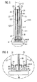
Figuren 2 bis 6 verwiesen. Dabei hat ein Energiespeicher ESP1 zur Speicherung von elektrischer Energie zwei prismatische Flachzellen Z1 und Z2 (beispielsweise Lithium-Ionen-Zellen) mit jeweils einem (flachen) Zellkörper ZK, der begrenzt wird durch zwei zu einer Zellkörperebene parallel verlaufende Grundflächen G11, G12 bzw. G21, G22 sowie durch eine erste ZB (Zellboden) und mehrere zweite ZD (hier lediglich die Seitenflächen am oberen Abschnitt der Zelle bezeichnet) senkrecht zur Zellkörperebene ZE verlaufende Seitenflächen, die die Grundflächen verbinden. Eine Kühlvorrichtung des Energiespeichers ESP1 umfasst ein Kühlelement bzw. einen Kühlfuß KF, der mit einem jeweiligen Zellboden ZB thermisch gekoppelt ist, um über den Zellboden ZB Wärme aus den Flachzellen Z1 und Z2 abzuführen. Ferner ist eine wärmeleitende Verbindungsschicht WLM vorgesehen, die zwischen dem jeweiligen Zellboden ZB und dem Kühlfuß KF angeordnet ist. Der Kühlfuß KF hat jeweils Ausnehmungen KA zur Aufnahme von Siegelnähten SN, die die Flachzellen aufgrund ihrer Folienverpackungen aufweisen. - Desweiteren hat die Kühlvorrichtung eine Kühlplatte in Form eines Kühlblechs KB, das mit einer der Grundflächen G12 und G21 der Flachzellen Z1 und Z2 thermisch gekoppelt ist. Das Kühlblech KB ist dabei fest mit dem Kühlfuß KF verbunden. Ein Kühlkörper KK dient als Wärmesenke für den Kühlfuß KF und das Kühlblech KB.
- Bei den in den
Figuren 2 bis 6 dargestellten Ausführungsformen der Erfindung besteht die Idee darin, dass die Ableitung der Wärme zusätzlich zu dem Kühlblech KB (Kühlplatte) über den Zellboden ZB (eine erste Seitenfläche) erfolgt. Dies wird mit dem Kühlfuß KF (als Kühlelement) realisiert, der über die wärmeleitende Verbindung (wie beispielsweise aus PU-Schaum, GAP-Filler, Thermo-Pad, Wärmeleitpaste, dünnen Schaumstoff, doppelseitiges Klebeband, usw.) WLM zwischen Zellboden und Kühlfuß an den Kühlkörper KK angebunden ist. Für die Siegelnaht SN der Zellen (sofern vorhanden) ist eine entsprechende Ausnehmung bzw. ein entsprechender Hohlraum KA in dem Kühlfuß vorgesehen. - Um das Kühlblech KB fest mit einem Wärmetauscher (realisiert durch den Kühlkörper KK) zu kontaktieren und zur weiteren Wärmeleitung ist das Kühlblech KB, wie bereits angedeutet, fest mit dem Kühlfuß KF verbunden (z.B. durch eine Klemm-, Steck-, Niet-, Schraub- oder Schweißverbindung). Kühlbleche, auch als Kühlfinnen bezeichnet, bestehen häufig aus zwei Bauteilen, da die Form von Finne und Kühlfuß weit außerhalb des Normkreises für Alu-Druckguss liegt.
- Die Wärme wird so vom Zellboden ZB in den Kühlfuß KF und vom Kühlfuß in den Kühlkörper KK geleitet, ohne Umweg über das Kühlblech KB. Dadurch wird die Wärmeleitung an einer thermodynamisch kritischen Stelle optimiert sowie die Entstehung von Hotspots an der Zellunterseite unter vergleichbaren Bedingungen vermieden.
- Insbesondere in den
Figuren 3 - 6 ist der schematische Aufbau der Kopplung Zelle dargestellt. Die Ausformung des Kühlfußes kann dabei ebenso variieren wie das Herstellungsverfahren desselben. Neben z.B. einem Strangpressprofil sind entsprechend gebogene Bleche im Verbund und andere Varianten denkbar. - Für die variierende Position der Siegelnaht SN unterschiedlicher Zellen, muss eine Umformung des Kühlfußes hinsichtlich der Lage des Hohlraumes berücksichtigt werden.
Claims (8)
- Energiespeicher (ESP1) zur Speicherung von elektrischer Energie, insbesondere für ein Kraftfahrzeug, mit folgenden Merkmalen:zumindest einer Flachzelle (Z1, Z2) mit einem flachen Zellkörper (ZK), der begrenzt wird durch zwei zu einer Zellkörperebene parallel verlaufende Grundflächen (G11, G12), sowie durch eine erste (ZB) und mehrere zweite (ZD) senkrecht zur Zellkörperebene (ZE) verlaufende Seitenflächen, die die Grundflächen (G11, G12) verbinden;einer Kühlvorrichtung mit einem Kühlelement (KF), das mit der ersten Seitenfläche (ZB) thermisch gekoppelt ist, um über diese Seitenfläche Wärme aus der Flachzelle abzuführen, und einer wärmeleitenden Verbindungsschicht (WLM), die zwischen der ersten Seitenfläche (ZB) und dem Kühlelement (KF) angeordnet ist, dadurch gekennzeichnet, dassdie wärmeleitende Verbindungsschicht (WLM) einen thermisch leitenden Polyurethanschaum, ein Wärmekissen, eine Wärmeleitpaste oder einen thermisch leitenden Schaumstoff umfasst.
- Energiespeicher nach einem der Ansprüche 1, bei dem der Zellkörper (ZK) der zumindest einen Flachzelle (Z1) eine den Zellkörper umgebende Verpackung aufweist, die zumindest entlang der ersten Seitenfläche einen vom Zellkörper (ZK) wegstehenden Verbindungsabschnitt (SN) aufweist.
- Energiespeicher nach Anspruch 2, bei dem das Kühlelement (KF) zumindest eine Ausnehmung (KA) zur Aufnahme des von der ersten Seitenfläche wegstehenden Verbindungsabschnitts (SN) aufweist.
- Energiespeicher nach einem der Ansprüche 1 bis 3, bei dem die Kühlvorrichtung ferner eine Kühlplatte (KB) aufweist, die mit einer der Grundflächen (G12) der zumindest einen Flachzelle thermisch gekoppelt ist.
- Energiespeicher nach Anspruch 4, bei dem die Kühlplatte (KB) mit dem Kühlelement (KF) verbunden ist.
- Energiespeicher nach einem der Ansprüche 4 bis 5, der zumindest zwei Flachzellen (Z1, Z2) aufweist, die jeweils mit einer Grundfläche (G12, G21) mit der Kühlplatte (KB) und jeweils mit der ersten Seitenfläche (ZB) mit dem Kühlelement (KF) verbunden sind.
- Energiespeicheranordnung mit einem Energiespeicher (ESP1) nach einem der vorangegangenen Ansprüche und einem Kühlkörper (KK), der als Wärmesenke für das Kühlelement (KF) und gegebenenfalls die Kühlplatte (KB) dient, und mit dem Kühlelement und/oder der Kühlplatte verbunden ist.
- Kraftfahrzeug mit einer Energiespeicheranordnung nach Anspruch 7.
Applications Claiming Priority (2)
| Application Number | Priority Date | Filing Date | Title |
|---|---|---|---|
| DE200810061277 DE102008061277A1 (de) | 2008-12-10 | 2008-12-10 | Energiespeicher |
| PCT/EP2009/066341 WO2010066637A1 (de) | 2008-12-10 | 2009-12-03 | Energiespeicher |
Publications (2)
| Publication Number | Publication Date |
|---|---|
| EP2377194A1 EP2377194A1 (de) | 2011-10-19 |
| EP2377194B1 true EP2377194B1 (de) | 2014-04-30 |
Family
ID=41600722
Family Applications (1)
| Application Number | Title | Priority Date | Filing Date |
|---|---|---|---|
| EP09765093.1A Active EP2377194B1 (de) | 2008-12-10 | 2009-12-03 | Energiespeicher mit einer kühlvorrichtung |
Country Status (6)
| Country | Link |
|---|---|
| US (1) | US20110244299A1 (de) |
| EP (1) | EP2377194B1 (de) |
| KR (1) | KR20110100273A (de) |
| CN (1) | CN102246340A (de) |
| DE (1) | DE102008061277A1 (de) |
| WO (1) | WO2010066637A1 (de) |
Families Citing this family (29)
| Publication number | Priority date | Publication date | Assignee | Title |
|---|---|---|---|---|
| PL211980B1 (pl) * | 2008-12-16 | 2012-07-31 | Impact Automotive Technologies Społka Z Ograniczoną Odpowiedzialnością | Moduł baterii elektrycznych stabilizowany termicznie |
| DE102010036686B4 (de) * | 2010-07-28 | 2020-05-28 | Intilion Gmbh | Vorrichtung zur Aufnahme eines galvanischen Elementes, Energiespeichereinheit sowie Energiespeicherstack |
| DE102010036062A1 (de) * | 2010-09-01 | 2012-03-01 | Ads-Tec Gmbh | Akkupack |
| DE102010062858B4 (de) | 2010-12-10 | 2023-06-01 | Robert Bosch Gmbh | Batteriezelle |
| US8771382B2 (en) * | 2011-02-25 | 2014-07-08 | GM Global Technology Operations LLC | Heat shrink joining of battery cell components |
| US9368770B2 (en) | 2011-03-23 | 2016-06-14 | GM Global Technology Operations LLC | Battery cooling module foot profile design for a jointless conductive FIN/foot compressed interface connection |
| CN103718374B (zh) * | 2011-04-15 | 2017-11-03 | 约翰逊控制技术有限责任公司 | 具有外部热管理系统的电池系统 |
| EP2786439B1 (de) * | 2011-11-30 | 2016-08-31 | ads-tec GmbH | Flachzelle für ein akkupack |
| AT13313U1 (de) * | 2012-02-08 | 2013-10-15 | Avl List Gmbh | Elektrischer Energiespeicher |
| KR20130112605A (ko) * | 2012-04-04 | 2013-10-14 | 현대자동차주식회사 | 배터리 셀 모듈용 방열 플레이트 및 이를 갖는 배터리 셀 모듈 |
| JP5591280B2 (ja) * | 2012-04-13 | 2014-09-17 | トヨタ自動車株式会社 | 電池、組電池 |
| WO2013168856A1 (ko) * | 2012-05-08 | 2013-11-14 | 주식회사 엘지화학 | 높은 효율성의 냉각 구조를 포함하는 전지모듈 |
| KR101459828B1 (ko) * | 2012-08-07 | 2014-11-10 | 현대자동차주식회사 | 배터리 셀 모듈용 다기능 방열 플레이트 및 이를 갖는 배터리 셀 모듈 |
| KR102029209B1 (ko) * | 2012-11-07 | 2019-10-07 | 에스케이이노베이션 주식회사 | 전지모듈 |
| JP5904113B2 (ja) * | 2012-12-10 | 2016-04-13 | 株式会社豊田自動織機 | 電池モジュール及び電池モジュールの製造方法 |
| KR102028916B1 (ko) * | 2012-12-31 | 2019-10-08 | 에스케이이노베이션 주식회사 | 이차 전지용 배터리 팩 |
| US10199695B2 (en) | 2014-08-18 | 2019-02-05 | Johnson Controls Technology Company | Battery module with restrained battery cells utilizing a heat exchanger |
| JP2017027796A (ja) * | 2015-07-22 | 2017-02-02 | 株式会社豊田自動織機 | 電池モジュール及び電池パック |
| US10305152B2 (en) * | 2016-09-26 | 2019-05-28 | Hyundai Motor Company | Water cooling system for a battery |
| EP3352290B1 (de) | 2017-01-19 | 2024-07-17 | 3M Innovative Properties Company | Aziridinfunktionales wärmeleitendes polyether-spaltenfüllmaterial |
| KR102258174B1 (ko) | 2017-04-26 | 2021-05-28 | 주식회사 엘지에너지솔루션 | 배터리 모듈, 이러한 배터리 모듈을 포함하는 배터리 팩 및 이러한 배터리 팩을 포함하는 자동차 |
| KR102410517B1 (ko) * | 2017-08-11 | 2022-06-20 | 현대자동차주식회사 | 배터리 모듈 |
| DE102017009712A1 (de) | 2017-10-18 | 2018-04-19 | Daimler Ag | Energiespeicher zum Speichern von elektrischer Energie für ein Kraftfahrzeug, insbesondere für einen Kraftwagen |
| DE102017129250B4 (de) * | 2017-12-08 | 2024-02-15 | Lisa Dräxlmaier GmbH | Kühlvorrichtung, Fahrzeug sowie Verfahren |
| KR102389911B1 (ko) * | 2018-09-17 | 2022-04-21 | 주식회사 엘지에너지솔루션 | 모듈 하우징을 포함하는 배터리 모듈 |
| KR102378527B1 (ko) | 2018-12-05 | 2022-03-23 | 주식회사 엘지에너지솔루션 | 전지 모듈 및 그 제조 방법 |
| KR102757441B1 (ko) * | 2019-11-26 | 2025-01-17 | 주식회사 엘지에너지솔루션 | 배터리 모듈 |
| JP7503933B2 (ja) * | 2020-04-23 | 2024-06-21 | 株式会社豊田中央研究所 | 電池パック |
| US20230043355A1 (en) * | 2021-08-04 | 2023-02-09 | Lg Energy Solution, Ltd. | Battery pack and vehicle including the same |
Citations (2)
| Publication number | Priority date | Publication date | Assignee | Title |
|---|---|---|---|---|
| JPH076796A (ja) * | 1993-06-17 | 1995-01-10 | Mitsubishi Alum Co Ltd | 車載用バッテリーケース |
| EP2065963A2 (de) * | 2007-11-29 | 2009-06-03 | Sanyo Electric Co., Ltd. | Über ein Kühlmittel gekühltes Batteriesystem |
Family Cites Families (11)
| Publication number | Priority date | Publication date | Assignee | Title |
|---|---|---|---|---|
| JPH07282841A (ja) * | 1994-04-05 | 1995-10-27 | Mitsubishi Chem Corp | リチウムイオン二次電池 |
| JP3451142B2 (ja) * | 1994-11-18 | 2003-09-29 | 本田技研工業株式会社 | 温度制御機構を備えたバッテリ組立体 |
| US6503658B1 (en) * | 2001-07-11 | 2003-01-07 | Electro Energy, Inc. | Bipolar electrochemical battery of stacked wafer cells |
| JP2005506658A (ja) * | 2001-10-09 | 2005-03-03 | エレクトラスター,エルエルシー | ニッケル水素バッテリ |
| US20050026014A1 (en) * | 2003-07-31 | 2005-02-03 | Michael Fogaing | Polymer batteries having thermal exchange apparatus |
| JP4374947B2 (ja) | 2003-08-25 | 2009-12-02 | 日産自動車株式会社 | 冷却用タブを有する積層型バイポーラ二次電池 |
| JP4839955B2 (ja) * | 2006-05-11 | 2011-12-21 | トヨタ自動車株式会社 | 電池パックおよび車両 |
| JP2008159440A (ja) * | 2006-12-25 | 2008-07-10 | Calsonic Kansei Corp | 車両用バッテリ冷却システム |
| CN101675543B (zh) | 2007-03-05 | 2013-05-01 | Temic汽车电机有限公司 | 带导热板的蓄能电池 |
| KR101477974B1 (ko) * | 2007-03-05 | 2015-01-02 | 테믹 오토모티브 일렉트릭 모터스 게엠베하 | 전력 저장 전지를 결합하고 보관하기 위한 장치 |
| EP2153487B1 (de) * | 2007-04-05 | 2013-06-19 | Behr GmbH & Co. KG | Elektrochemische energiespeichereinheit mit kühlvorrichtung |
-
2008
- 2008-12-10 DE DE200810061277 patent/DE102008061277A1/de not_active Withdrawn
-
2009
- 2009-12-03 WO PCT/EP2009/066341 patent/WO2010066637A1/de not_active Ceased
- 2009-12-03 US US13/139,059 patent/US20110244299A1/en not_active Abandoned
- 2009-12-03 KR KR1020117016081A patent/KR20110100273A/ko not_active Withdrawn
- 2009-12-03 CN CN2009801497127A patent/CN102246340A/zh active Pending
- 2009-12-03 EP EP09765093.1A patent/EP2377194B1/de active Active
Patent Citations (2)
| Publication number | Priority date | Publication date | Assignee | Title |
|---|---|---|---|---|
| JPH076796A (ja) * | 1993-06-17 | 1995-01-10 | Mitsubishi Alum Co Ltd | 車載用バッテリーケース |
| EP2065963A2 (de) * | 2007-11-29 | 2009-06-03 | Sanyo Electric Co., Ltd. | Über ein Kühlmittel gekühltes Batteriesystem |
Also Published As
| Publication number | Publication date |
|---|---|
| EP2377194A1 (de) | 2011-10-19 |
| CN102246340A (zh) | 2011-11-16 |
| KR20110100273A (ko) | 2011-09-09 |
| DE102008061277A1 (de) | 2010-06-24 |
| US20110244299A1 (en) | 2011-10-06 |
| WO2010066637A1 (de) | 2010-06-17 |
Similar Documents
| Publication | Publication Date | Title |
|---|---|---|
| EP2377194A1 (de) | Energiespeicher | |
| DE102008034860B4 (de) | Batterie mit einem Batteriegehäuse und einer Wärmeleitplatte zum Temperieren der Batterie | |
| DE60213474T2 (de) | Vorrichtung und verfahren zur temperaturkontrolle bei elektrochemischen zellen mit hoher energiedichte | |
| EP2476160B1 (de) | Verfahren zur herstellung eines energiespeicherhalters für ein fahrzeug | |
| EP3963657B1 (de) | Temperiersystem für lithium-ionen-batteriezellen | |
| EP2382678B1 (de) | Batteriemodul mit isolierendem schichtelement | |
| DE102019117875A1 (de) | Batteriemodul | |
| WO2008106946A2 (de) | Energiespeicherzelle mit wärmeleitplatte | |
| DE102017101305B4 (de) | Batteriezelle mit innerzelligem wärmeleitendem Element | |
| DE102008034873A1 (de) | Batterie, insbesondere Fahrzeugbatterie | |
| WO2010063365A1 (de) | Batterie und verfahren zur herstellung einer batterie | |
| EP4047717B1 (de) | Batterie | |
| DE102009044997A1 (de) | Thermische Entkopplung von Nachbarzellen in einem Batteriesystem | |
| EP2414185A2 (de) | Vorrichtung zur thermischen anbindung eines energiespeichers | |
| WO2018065516A1 (de) | Energiespeichermodul mit einem temperaturmanagement-system und ein energiespeichersystem | |
| DE102014019074A1 (de) | Zellblock für eine Kraftfahrzeugbatterie | |
| DE102016225192A1 (de) | Wärmeverteiler für eine Batterie | |
| DE102012218764A1 (de) | Kühlfinne zum Kühlen einer elektrochemischen Zelle sowie Energiespeicher und Batteriemodul mit Kühlfinne und Zelle | |
| WO2014048620A1 (de) | Elektrisches energiespeichermodul und verfahren zum herstellen eines elektrischen energiespeichermoduls | |
| WO2021073922A1 (de) | Batteriezelle, batterieanordnung und verfahren zum entwärmen einer batteriezelle | |
| EP4059082B1 (de) | Batteriezelle für einen elektrischen energiespeicher und elektrischer energiespeicher | |
| EP2319119A1 (de) | Galvanisches element | |
| DE102014103095A1 (de) | Energiespeichereinheit und Batteriesystem | |
| DE102020005410A1 (de) | Energiespeicheranordnung | |
| DE102022134076A1 (de) | Batterie mit optimierter Temperierbarkeit |
Legal Events
| Date | Code | Title | Description |
|---|---|---|---|
| PUAI | Public reference made under article 153(3) epc to a published international application that has entered the european phase |
Free format text: ORIGINAL CODE: 0009012 |
|
| 17P | Request for examination filed |
Effective date: 20110711 |
|
| AK | Designated contracting states |
Kind code of ref document: A1 Designated state(s): AT BE BG CH CY CZ DE DK EE ES FI FR GB GR HR HU IE IS IT LI LT LU LV MC MK MT NL NO PL PT RO SE SI SK SM TR |
|
| DAX | Request for extension of the european patent (deleted) | ||
| 17Q | First examination report despatched |
Effective date: 20120710 |
|
| RIC1 | Information provided on ipc code assigned before grant |
Ipc: B60L 11/18 20060101AFI20121113BHEP Ipc: H01M 10/50 20060101ALI20121113BHEP Ipc: H01M 10/04 20060101ALI20121113BHEP |
|
| RIC1 | Information provided on ipc code assigned before grant |
Ipc: H01M 10/0525 20100101ALN20131105BHEP Ipc: H01M 10/50 20060101ALI20131105BHEP Ipc: H01M 10/04 20060101AFI20131105BHEP Ipc: B60L 11/18 20060101ALI20131105BHEP |
|
| GRAP | Despatch of communication of intention to grant a patent |
Free format text: ORIGINAL CODE: EPIDOSNIGR1 |
|
| RIC1 | Information provided on ipc code assigned before grant |
Ipc: H01M 10/04 20060101AFI20131127BHEP Ipc: H01M 10/0525 20100101ALN20131127BHEP Ipc: B60L 11/18 20060101ALI20131127BHEP Ipc: H01M 10/50 20060101ALI20131127BHEP |
|
| RIC1 | Information provided on ipc code assigned before grant |
Ipc: H01M 10/04 20060101AFI20131202BHEP Ipc: H01M 10/50 20060101ALI20131202BHEP Ipc: H01M 10/0525 20100101ALN20131202BHEP Ipc: B60L 11/18 20060101ALI20131202BHEP |
|
| INTG | Intention to grant announced |
Effective date: 20131219 |
|
| GRAS | Grant fee paid |
Free format text: ORIGINAL CODE: EPIDOSNIGR3 |
|
| GRAA | (expected) grant |
Free format text: ORIGINAL CODE: 0009210 |
|
| AK | Designated contracting states |
Kind code of ref document: B1 Designated state(s): AT BE BG CH CY CZ DE DK EE ES FI FR GB GR HR HU IE IS IT LI LT LU LV MC MK MT NL NO PL PT RO SE SI SK SM TR |
|
| REG | Reference to a national code |
Ref country code: GB Ref legal event code: FG4D Free format text: NOT ENGLISH Ref country code: CH Ref legal event code: EP |
|
| RIC1 | Information provided on ipc code assigned before grant |
Ipc: H01M 10/04 20060101AFI20140325BHEP Ipc: B60L 11/18 20060101ALI20140325BHEP Ipc: H01M 10/0525 20100101ALN20140325BHEP Ipc: H01M 10/60 20140101ALI20140325BHEP |
|
| REG | Reference to a national code |
Ref country code: AT Ref legal event code: REF Ref document number: 665652 Country of ref document: AT Kind code of ref document: T Effective date: 20140515 |
|
| REG | Reference to a national code |
Ref country code: IE Ref legal event code: FG4D Free format text: LANGUAGE OF EP DOCUMENT: GERMAN |
|
| REG | Reference to a national code |
Ref country code: DE Ref legal event code: R096 Ref document number: 502009009307 Country of ref document: DE Effective date: 20140612 |
|
| REG | Reference to a national code |
Ref country code: LT Ref legal event code: MG4D |
|
| REG | Reference to a national code |
Ref country code: NL Ref legal event code: VDEP Effective date: 20140430 |
|
| PG25 | Lapsed in a contracting state [announced via postgrant information from national office to epo] |
Ref country code: GR Free format text: LAPSE BECAUSE OF FAILURE TO SUBMIT A TRANSLATION OF THE DESCRIPTION OR TO PAY THE FEE WITHIN THE PRESCRIBED TIME-LIMIT Effective date: 20140731 Ref country code: IS Free format text: LAPSE BECAUSE OF FAILURE TO SUBMIT A TRANSLATION OF THE DESCRIPTION OR TO PAY THE FEE WITHIN THE PRESCRIBED TIME-LIMIT Effective date: 20140830 Ref country code: NO Free format text: LAPSE BECAUSE OF FAILURE TO SUBMIT A TRANSLATION OF THE DESCRIPTION OR TO PAY THE FEE WITHIN THE PRESCRIBED TIME-LIMIT Effective date: 20140730 Ref country code: LT Free format text: LAPSE BECAUSE OF FAILURE TO SUBMIT A TRANSLATION OF THE DESCRIPTION OR TO PAY THE FEE WITHIN THE PRESCRIBED TIME-LIMIT Effective date: 20140430 Ref country code: BG Free format text: LAPSE BECAUSE OF FAILURE TO SUBMIT A TRANSLATION OF THE DESCRIPTION OR TO PAY THE FEE WITHIN THE PRESCRIBED TIME-LIMIT Effective date: 20140730 Ref country code: CY Free format text: LAPSE BECAUSE OF FAILURE TO SUBMIT A TRANSLATION OF THE DESCRIPTION OR TO PAY THE FEE WITHIN THE PRESCRIBED TIME-LIMIT Effective date: 20140430 Ref country code: FI Free format text: LAPSE BECAUSE OF FAILURE TO SUBMIT A TRANSLATION OF THE DESCRIPTION OR TO PAY THE FEE WITHIN THE PRESCRIBED TIME-LIMIT Effective date: 20140430 Ref country code: NL Free format text: LAPSE BECAUSE OF FAILURE TO SUBMIT A TRANSLATION OF THE DESCRIPTION OR TO PAY THE FEE WITHIN THE PRESCRIBED TIME-LIMIT Effective date: 20140430 |
|
| PG25 | Lapsed in a contracting state [announced via postgrant information from national office to epo] |
Ref country code: PL Free format text: LAPSE BECAUSE OF FAILURE TO SUBMIT A TRANSLATION OF THE DESCRIPTION OR TO PAY THE FEE WITHIN THE PRESCRIBED TIME-LIMIT Effective date: 20140430 Ref country code: ES Free format text: LAPSE BECAUSE OF FAILURE TO SUBMIT A TRANSLATION OF THE DESCRIPTION OR TO PAY THE FEE WITHIN THE PRESCRIBED TIME-LIMIT Effective date: 20140430 Ref country code: HR Free format text: LAPSE BECAUSE OF FAILURE TO SUBMIT A TRANSLATION OF THE DESCRIPTION OR TO PAY THE FEE WITHIN THE PRESCRIBED TIME-LIMIT Effective date: 20140430 Ref country code: SE Free format text: LAPSE BECAUSE OF FAILURE TO SUBMIT A TRANSLATION OF THE DESCRIPTION OR TO PAY THE FEE WITHIN THE PRESCRIBED TIME-LIMIT Effective date: 20140430 Ref country code: LV Free format text: LAPSE BECAUSE OF FAILURE TO SUBMIT A TRANSLATION OF THE DESCRIPTION OR TO PAY THE FEE WITHIN THE PRESCRIBED TIME-LIMIT Effective date: 20140430 |
|
| PG25 | Lapsed in a contracting state [announced via postgrant information from national office to epo] |
Ref country code: PT Free format text: LAPSE BECAUSE OF FAILURE TO SUBMIT A TRANSLATION OF THE DESCRIPTION OR TO PAY THE FEE WITHIN THE PRESCRIBED TIME-LIMIT Effective date: 20140901 |
|
| PG25 | Lapsed in a contracting state [announced via postgrant information from national office to epo] |
Ref country code: DK Free format text: LAPSE BECAUSE OF FAILURE TO SUBMIT A TRANSLATION OF THE DESCRIPTION OR TO PAY THE FEE WITHIN THE PRESCRIBED TIME-LIMIT Effective date: 20140430 Ref country code: SK Free format text: LAPSE BECAUSE OF FAILURE TO SUBMIT A TRANSLATION OF THE DESCRIPTION OR TO PAY THE FEE WITHIN THE PRESCRIBED TIME-LIMIT Effective date: 20140430 Ref country code: CZ Free format text: LAPSE BECAUSE OF FAILURE TO SUBMIT A TRANSLATION OF THE DESCRIPTION OR TO PAY THE FEE WITHIN THE PRESCRIBED TIME-LIMIT Effective date: 20140430 Ref country code: RO Free format text: LAPSE BECAUSE OF FAILURE TO SUBMIT A TRANSLATION OF THE DESCRIPTION OR TO PAY THE FEE WITHIN THE PRESCRIBED TIME-LIMIT Effective date: 20140430 Ref country code: EE Free format text: LAPSE BECAUSE OF FAILURE TO SUBMIT A TRANSLATION OF THE DESCRIPTION OR TO PAY THE FEE WITHIN THE PRESCRIBED TIME-LIMIT Effective date: 20140430 |
|
| REG | Reference to a national code |
Ref country code: DE Ref legal event code: R097 Ref document number: 502009009307 Country of ref document: DE |
|
| PLBE | No opposition filed within time limit |
Free format text: ORIGINAL CODE: 0009261 |
|
| STAA | Information on the status of an ep patent application or granted ep patent |
Free format text: STATUS: NO OPPOSITION FILED WITHIN TIME LIMIT |
|
| PG25 | Lapsed in a contracting state [announced via postgrant information from national office to epo] |
Ref country code: IT Free format text: LAPSE BECAUSE OF FAILURE TO SUBMIT A TRANSLATION OF THE DESCRIPTION OR TO PAY THE FEE WITHIN THE PRESCRIBED TIME-LIMIT Effective date: 20140430 |
|
| 26N | No opposition filed |
Effective date: 20150202 |
|
| REG | Reference to a national code |
Ref country code: DE Ref legal event code: R097 Ref document number: 502009009307 Country of ref document: DE Effective date: 20150202 |
|
| PG25 | Lapsed in a contracting state [announced via postgrant information from national office to epo] |
Ref country code: BE Free format text: LAPSE BECAUSE OF NON-PAYMENT OF DUE FEES Effective date: 20141231 |
|
| PG25 | Lapsed in a contracting state [announced via postgrant information from national office to epo] |
Ref country code: LU Free format text: LAPSE BECAUSE OF FAILURE TO SUBMIT A TRANSLATION OF THE DESCRIPTION OR TO PAY THE FEE WITHIN THE PRESCRIBED TIME-LIMIT Effective date: 20141203 Ref country code: SI Free format text: LAPSE BECAUSE OF FAILURE TO SUBMIT A TRANSLATION OF THE DESCRIPTION OR TO PAY THE FEE WITHIN THE PRESCRIBED TIME-LIMIT Effective date: 20140430 |
|
| REG | Reference to a national code |
Ref country code: CH Ref legal event code: PL |
|
| GBPC | Gb: european patent ceased through non-payment of renewal fee |
Effective date: 20141203 |
|
| REG | Reference to a national code |
Ref country code: IE Ref legal event code: MM4A |
|
| PG25 | Lapsed in a contracting state [announced via postgrant information from national office to epo] |
Ref country code: LI Free format text: LAPSE BECAUSE OF NON-PAYMENT OF DUE FEES Effective date: 20141231 Ref country code: GB Free format text: LAPSE BECAUSE OF NON-PAYMENT OF DUE FEES Effective date: 20141203 Ref country code: IE Free format text: LAPSE BECAUSE OF NON-PAYMENT OF DUE FEES Effective date: 20141203 Ref country code: CH Free format text: LAPSE BECAUSE OF NON-PAYMENT OF DUE FEES Effective date: 20141231 |
|
| REG | Reference to a national code |
Ref country code: FR Ref legal event code: PLFP Year of fee payment: 7 |
|
| REG | Reference to a national code |
Ref country code: AT Ref legal event code: MM01 Ref document number: 665652 Country of ref document: AT Kind code of ref document: T Effective date: 20141203 |
|
| PG25 | Lapsed in a contracting state [announced via postgrant information from national office to epo] |
Ref country code: SM Free format text: LAPSE BECAUSE OF FAILURE TO SUBMIT A TRANSLATION OF THE DESCRIPTION OR TO PAY THE FEE WITHIN THE PRESCRIBED TIME-LIMIT Effective date: 20140430 |
|
| PG25 | Lapsed in a contracting state [announced via postgrant information from national office to epo] |
Ref country code: AT Free format text: LAPSE BECAUSE OF NON-PAYMENT OF DUE FEES Effective date: 20141203 Ref country code: MC Free format text: LAPSE BECAUSE OF FAILURE TO SUBMIT A TRANSLATION OF THE DESCRIPTION OR TO PAY THE FEE WITHIN THE PRESCRIBED TIME-LIMIT Effective date: 20140430 |
|
| PG25 | Lapsed in a contracting state [announced via postgrant information from national office to epo] |
Ref country code: HU Free format text: LAPSE BECAUSE OF FAILURE TO SUBMIT A TRANSLATION OF THE DESCRIPTION OR TO PAY THE FEE WITHIN THE PRESCRIBED TIME-LIMIT; INVALID AB INITIO Effective date: 20091203 Ref country code: MT Free format text: LAPSE BECAUSE OF FAILURE TO SUBMIT A TRANSLATION OF THE DESCRIPTION OR TO PAY THE FEE WITHIN THE PRESCRIBED TIME-LIMIT Effective date: 20140430 Ref country code: TR Free format text: LAPSE BECAUSE OF FAILURE TO SUBMIT A TRANSLATION OF THE DESCRIPTION OR TO PAY THE FEE WITHIN THE PRESCRIBED TIME-LIMIT Effective date: 20140430 |
|
| REG | Reference to a national code |
Ref country code: FR Ref legal event code: PLFP Year of fee payment: 8 |
|
| REG | Reference to a national code |
Ref country code: FR Ref legal event code: PLFP Year of fee payment: 9 |
|
| PG25 | Lapsed in a contracting state [announced via postgrant information from national office to epo] |
Ref country code: MK Free format text: LAPSE BECAUSE OF FAILURE TO SUBMIT A TRANSLATION OF THE DESCRIPTION OR TO PAY THE FEE WITHIN THE PRESCRIBED TIME-LIMIT Effective date: 20140430 |
|
| REG | Reference to a national code |
Ref country code: DE Ref legal event code: R081 Ref document number: 502009009307 Country of ref document: DE Owner name: VITESCO TECHNOLOGIES GMBH, DE Free format text: FORMER OWNER: CONTINENTAL AUTOMOTIVE GMBH, 30165 HANNOVER, DE |
|
| REG | Reference to a national code |
Ref country code: DE Ref legal event code: R084 Ref document number: 502009009307 Country of ref document: DE |
|
| REG | Reference to a national code |
Ref country code: DE Ref legal event code: R081 Ref document number: 502009009307 Country of ref document: DE Owner name: SCHAEFFLER TECHNOLOGIES AG & CO. KG, DE Free format text: FORMER OWNER: VITESCO TECHNOLOGIES GMBH, 30165 HANNOVER, DE Ref country code: DE Ref legal event code: R081 Ref document number: 502009009307 Country of ref document: DE Owner name: VITESCO TECHNOLOGIES GMBH, DE Free format text: FORMER OWNER: VITESCO TECHNOLOGIES GMBH, 30165 HANNOVER, DE |
|
| P01 | Opt-out of the competence of the unified patent court (upc) registered |
Effective date: 20230530 |
|
| REG | Reference to a national code |
Ref country code: DE Ref legal event code: R081 Ref document number: 502009009307 Country of ref document: DE Owner name: SCHAEFFLER TECHNOLOGIES AG & CO. KG, DE Free format text: FORMER OWNER: VITESCO TECHNOLOGIES GMBH, 93055 REGENSBURG, DE |
|
| PGFP | Annual fee paid to national office [announced via postgrant information from national office to epo] |
Ref country code: FR Payment date: 20251222 Year of fee payment: 17 |
|
| PGFP | Annual fee paid to national office [announced via postgrant information from national office to epo] |
Ref country code: DE Payment date: 20251231 Year of fee payment: 17 |