US10199695B2 - Battery module with restrained battery cells utilizing a heat exchanger - Google Patents
Battery module with restrained battery cells utilizing a heat exchanger Download PDFInfo
- Publication number
- US10199695B2 US10199695B2 US14/805,404 US201514805404A US10199695B2 US 10199695 B2 US10199695 B2 US 10199695B2 US 201514805404 A US201514805404 A US 201514805404A US 10199695 B2 US10199695 B2 US 10199695B2
- Authority
- US
- United States
- Prior art keywords
- lithium ion
- ion battery
- battery module
- battery cells
- heat exchanger
- Prior art date
- Legal status (The legal status is an assumption and is not a legal conclusion. Google has not performed a legal analysis and makes no representation as to the accuracy of the status listed.)
- Active, expires
Links
Images


Classifications
-
- H—ELECTRICITY
- H01—ELECTRIC ELEMENTS
- H01M—PROCESSES OR MEANS, e.g. BATTERIES, FOR THE DIRECT CONVERSION OF CHEMICAL ENERGY INTO ELECTRICAL ENERGY
- H01M10/00—Secondary cells; Manufacture thereof
- H01M10/60—Heating or cooling; Temperature control
- H01M10/62—Heating or cooling; Temperature control specially adapted for specific applications
- H01M10/625—Vehicles
-
- H—ELECTRICITY
- H01—ELECTRIC ELEMENTS
- H01M—PROCESSES OR MEANS, e.g. BATTERIES, FOR THE DIRECT CONVERSION OF CHEMICAL ENERGY INTO ELECTRICAL ENERGY
- H01M10/00—Secondary cells; Manufacture thereof
- H01M10/05—Accumulators with non-aqueous electrolyte
- H01M10/052—Li-accumulators
- H01M10/0525—Rocking-chair batteries, i.e. batteries with lithium insertion or intercalation in both electrodes; Lithium-ion batteries
-
- H—ELECTRICITY
- H01—ELECTRIC ELEMENTS
- H01M—PROCESSES OR MEANS, e.g. BATTERIES, FOR THE DIRECT CONVERSION OF CHEMICAL ENERGY INTO ELECTRICAL ENERGY
- H01M10/00—Secondary cells; Manufacture thereof
- H01M10/05—Accumulators with non-aqueous electrolyte
- H01M10/058—Construction or manufacture
- H01M10/0585—Construction or manufacture of accumulators having only flat construction elements, i.e. flat positive electrodes, flat negative electrodes and flat separators
-
- H—ELECTRICITY
- H01—ELECTRIC ELEMENTS
- H01M—PROCESSES OR MEANS, e.g. BATTERIES, FOR THE DIRECT CONVERSION OF CHEMICAL ENERGY INTO ELECTRICAL ENERGY
- H01M10/00—Secondary cells; Manufacture thereof
- H01M10/42—Methods or arrangements for servicing or maintenance of secondary cells or secondary half-cells
- H01M10/48—Accumulators combined with arrangements for measuring, testing or indicating the condition of cells, e.g. the level or density of the electrolyte
- H01M10/486—Accumulators combined with arrangements for measuring, testing or indicating the condition of cells, e.g. the level or density of the electrolyte for measuring temperature
-
- H—ELECTRICITY
- H01—ELECTRIC ELEMENTS
- H01M—PROCESSES OR MEANS, e.g. BATTERIES, FOR THE DIRECT CONVERSION OF CHEMICAL ENERGY INTO ELECTRICAL ENERGY
- H01M10/00—Secondary cells; Manufacture thereof
- H01M10/60—Heating or cooling; Temperature control
- H01M10/63—Control systems
-
- H—ELECTRICITY
- H01—ELECTRIC ELEMENTS
- H01M—PROCESSES OR MEANS, e.g. BATTERIES, FOR THE DIRECT CONVERSION OF CHEMICAL ENERGY INTO ELECTRICAL ENERGY
- H01M10/00—Secondary cells; Manufacture thereof
- H01M10/60—Heating or cooling; Temperature control
- H01M10/64—Heating or cooling; Temperature control characterised by the shape of the cells
- H01M10/647—Prismatic or flat cells, e.g. pouch cells
-
- H—ELECTRICITY
- H01—ELECTRIC ELEMENTS
- H01M—PROCESSES OR MEANS, e.g. BATTERIES, FOR THE DIRECT CONVERSION OF CHEMICAL ENERGY INTO ELECTRICAL ENERGY
- H01M10/00—Secondary cells; Manufacture thereof
- H01M10/60—Heating or cooling; Temperature control
- H01M10/65—Means for temperature control structurally associated with the cells
- H01M10/653—Means for temperature control structurally associated with the cells characterised by electrically insulating or thermally conductive materials
-
- H—ELECTRICITY
- H01—ELECTRIC ELEMENTS
- H01M—PROCESSES OR MEANS, e.g. BATTERIES, FOR THE DIRECT CONVERSION OF CHEMICAL ENERGY INTO ELECTRICAL ENERGY
- H01M10/00—Secondary cells; Manufacture thereof
- H01M10/60—Heating or cooling; Temperature control
- H01M10/65—Means for temperature control structurally associated with the cells
- H01M10/655—Solid structures for heat exchange or heat conduction
- H01M10/6551—Surfaces specially adapted for heat dissipation or radiation, e.g. fins or coatings
-
- H—ELECTRICITY
- H01—ELECTRIC ELEMENTS
- H01M—PROCESSES OR MEANS, e.g. BATTERIES, FOR THE DIRECT CONVERSION OF CHEMICAL ENERGY INTO ELECTRICAL ENERGY
- H01M10/00—Secondary cells; Manufacture thereof
- H01M10/60—Heating or cooling; Temperature control
- H01M10/65—Means for temperature control structurally associated with the cells
- H01M10/655—Solid structures for heat exchange or heat conduction
- H01M10/6554—Rods or plates
- H01M10/6555—Rods or plates arranged between the cells
-
- H01M2/1077—
-
- H—ELECTRICITY
- H01—ELECTRIC ELEMENTS
- H01M—PROCESSES OR MEANS, e.g. BATTERIES, FOR THE DIRECT CONVERSION OF CHEMICAL ENERGY INTO ELECTRICAL ENERGY
- H01M4/00—Electrodes
- H01M4/02—Electrodes composed of, or comprising, active material
- H01M4/36—Selection of substances as active materials, active masses, active liquids
- H01M4/48—Selection of substances as active materials, active masses, active liquids of inorganic oxides or hydroxides
- H01M4/485—Selection of substances as active materials, active masses, active liquids of inorganic oxides or hydroxides of mixed oxides or hydroxides for inserting or intercalating light metals, e.g. LiTi2O4 or LiTi2OxFy
-
- H—ELECTRICITY
- H01—ELECTRIC ELEMENTS
- H01M—PROCESSES OR MEANS, e.g. BATTERIES, FOR THE DIRECT CONVERSION OF CHEMICAL ENERGY INTO ELECTRICAL ENERGY
- H01M4/00—Electrodes
- H01M4/02—Electrodes composed of, or comprising, active material
- H01M4/36—Selection of substances as active materials, active masses, active liquids
- H01M4/48—Selection of substances as active materials, active masses, active liquids of inorganic oxides or hydroxides
- H01M4/50—Selection of substances as active materials, active masses, active liquids of inorganic oxides or hydroxides of manganese
- H01M4/505—Selection of substances as active materials, active masses, active liquids of inorganic oxides or hydroxides of manganese of mixed oxides or hydroxides containing manganese for inserting or intercalating light metals, e.g. LiMn2O4 or LiMn2OxFy
-
- H—ELECTRICITY
- H01—ELECTRIC ELEMENTS
- H01M—PROCESSES OR MEANS, e.g. BATTERIES, FOR THE DIRECT CONVERSION OF CHEMICAL ENERGY INTO ELECTRICAL ENERGY
- H01M4/00—Electrodes
- H01M4/02—Electrodes composed of, or comprising, active material
- H01M4/36—Selection of substances as active materials, active masses, active liquids
- H01M4/48—Selection of substances as active materials, active masses, active liquids of inorganic oxides or hydroxides
- H01M4/52—Selection of substances as active materials, active masses, active liquids of inorganic oxides or hydroxides of nickel, cobalt or iron
- H01M4/525—Selection of substances as active materials, active masses, active liquids of inorganic oxides or hydroxides of nickel, cobalt or iron of mixed oxides or hydroxides containing iron, cobalt or nickel for inserting or intercalating light metals, e.g. LiNiO2, LiCoO2 or LiCoOxFy
-
- H—ELECTRICITY
- H01—ELECTRIC ELEMENTS
- H01M—PROCESSES OR MEANS, e.g. BATTERIES, FOR THE DIRECT CONVERSION OF CHEMICAL ENERGY INTO ELECTRICAL ENERGY
- H01M4/00—Electrodes
- H01M4/02—Electrodes composed of, or comprising, active material
- H01M4/36—Selection of substances as active materials, active masses, active liquids
- H01M4/58—Selection of substances as active materials, active masses, active liquids of inorganic compounds other than oxides or hydroxides, e.g. sulfides, selenides, tellurides, halogenides or LiCoFy; of polyanionic structures, e.g. phosphates, silicates or borates
- H01M4/583—Carbonaceous material, e.g. graphite-intercalation compounds or CFx
- H01M4/587—Carbonaceous material, e.g. graphite-intercalation compounds or CFx for inserting or intercalating light metals
-
- H—ELECTRICITY
- H01—ELECTRIC ELEMENTS
- H01M—PROCESSES OR MEANS, e.g. BATTERIES, FOR THE DIRECT CONVERSION OF CHEMICAL ENERGY INTO ELECTRICAL ENERGY
- H01M50/00—Constructional details or processes of manufacture of the non-active parts of electrochemical cells other than fuel cells, e.g. hybrid cells
- H01M50/20—Mountings; Secondary casings or frames; Racks, modules or packs; Suspension devices; Shock absorbers; Transport or carrying devices; Holders
- H01M50/204—Racks, modules or packs for multiple batteries or multiple cells
- H01M50/207—Racks, modules or packs for multiple batteries or multiple cells characterised by their shape
- H01M50/209—Racks, modules or packs for multiple batteries or multiple cells characterised by their shape adapted for prismatic or rectangular cells
-
- H—ELECTRICITY
- H01—ELECTRIC ELEMENTS
- H01M—PROCESSES OR MEANS, e.g. BATTERIES, FOR THE DIRECT CONVERSION OF CHEMICAL ENERGY INTO ELECTRICAL ENERGY
- H01M50/00—Constructional details or processes of manufacture of the non-active parts of electrochemical cells other than fuel cells, e.g. hybrid cells
- H01M50/20—Mountings; Secondary casings or frames; Racks, modules or packs; Suspension devices; Shock absorbers; Transport or carrying devices; Holders
- H01M50/289—Mountings; Secondary casings or frames; Racks, modules or packs; Suspension devices; Shock absorbers; Transport or carrying devices; Holders characterised by spacing elements or positioning means within frames, racks or packs
-
- H01M2/0217—
-
- H—ELECTRICITY
- H01—ELECTRIC ELEMENTS
- H01M—PROCESSES OR MEANS, e.g. BATTERIES, FOR THE DIRECT CONVERSION OF CHEMICAL ENERGY INTO ELECTRICAL ENERGY
- H01M4/00—Electrodes
- H01M4/02—Electrodes composed of, or comprising, active material
- H01M2004/026—Electrodes composed of, or comprising, active material characterised by the polarity
- H01M2004/027—Negative electrodes
-
- H—ELECTRICITY
- H01—ELECTRIC ELEMENTS
- H01M—PROCESSES OR MEANS, e.g. BATTERIES, FOR THE DIRECT CONVERSION OF CHEMICAL ENERGY INTO ELECTRICAL ENERGY
- H01M4/00—Electrodes
- H01M4/02—Electrodes composed of, or comprising, active material
- H01M2004/026—Electrodes composed of, or comprising, active material characterised by the polarity
- H01M2004/028—Positive electrodes
-
- H—ELECTRICITY
- H01—ELECTRIC ELEMENTS
- H01M—PROCESSES OR MEANS, e.g. BATTERIES, FOR THE DIRECT CONVERSION OF CHEMICAL ENERGY INTO ELECTRICAL ENERGY
- H01M2220/00—Batteries for particular applications
- H01M2220/20—Batteries in motive systems, e.g. vehicle, ship, plane
-
- H—ELECTRICITY
- H01—ELECTRIC ELEMENTS
- H01M—PROCESSES OR MEANS, e.g. BATTERIES, FOR THE DIRECT CONVERSION OF CHEMICAL ENERGY INTO ELECTRICAL ENERGY
- H01M50/00—Constructional details or processes of manufacture of the non-active parts of electrochemical cells other than fuel cells, e.g. hybrid cells
- H01M50/10—Primary casings, jackets or wrappings of a single cell or a single battery
- H01M50/102—Primary casings, jackets or wrappings of a single cell or a single battery characterised by their shape or physical structure
- H01M50/103—Primary casings, jackets or wrappings of a single cell or a single battery characterised by their shape or physical structure prismatic or rectangular
-
- Y—GENERAL TAGGING OF NEW TECHNOLOGICAL DEVELOPMENTS; GENERAL TAGGING OF CROSS-SECTIONAL TECHNOLOGIES SPANNING OVER SEVERAL SECTIONS OF THE IPC; TECHNICAL SUBJECTS COVERED BY FORMER USPC CROSS-REFERENCE ART COLLECTIONS [XRACs] AND DIGESTS
- Y02—TECHNOLOGIES OR APPLICATIONS FOR MITIGATION OR ADAPTATION AGAINST CLIMATE CHANGE
- Y02E—REDUCTION OF GREENHOUSE GAS [GHG] EMISSIONS, RELATED TO ENERGY GENERATION, TRANSMISSION OR DISTRIBUTION
- Y02E60/00—Enabling technologies; Technologies with a potential or indirect contribution to GHG emissions mitigation
- Y02E60/10—Energy storage using batteries
-
- Y—GENERAL TAGGING OF NEW TECHNOLOGICAL DEVELOPMENTS; GENERAL TAGGING OF CROSS-SECTIONAL TECHNOLOGIES SPANNING OVER SEVERAL SECTIONS OF THE IPC; TECHNICAL SUBJECTS COVERED BY FORMER USPC CROSS-REFERENCE ART COLLECTIONS [XRACs] AND DIGESTS
- Y02—TECHNOLOGIES OR APPLICATIONS FOR MITIGATION OR ADAPTATION AGAINST CLIMATE CHANGE
- Y02P—CLIMATE CHANGE MITIGATION TECHNOLOGIES IN THE PRODUCTION OR PROCESSING OF GOODS
- Y02P70/00—Climate change mitigation technologies in the production process for final industrial or consumer products
- Y02P70/50—Manufacturing or production processes characterised by the final manufactured product
Definitions
- the present disclosure relates generally to the field of batteries and battery modules. More specifically, the present disclosure relates to methods of restraining battery cells within battery modules.
- xEV A vehicle that uses one or more battery systems for providing all or a portion of the motive power for the vehicle can be referred to as an xEV, where the term “xEV” is defined herein to include all of the following vehicles, or any variations or combinations thereof, that use electric power for all or a portion of their vehicular motive force.
- xEVs include electric vehicles (EVs) that utilize electric power for all motive force.
- EVs electric vehicles
- hybrid electric vehicles (HEVs) also considered xEVs, combine an internal combustion engine propulsion system and a battery-powered electric propulsion system, such as 48 volt or 130 volt systems.
- the term HEV may include any variation of a hybrid electric vehicle.
- full hybrid systems may provide motive and other electrical power to the vehicle using one or more electric motors, using only an internal combustion engine, or using both.
- mild hybrid systems MHEVs
- MHEVs disable the internal combustion engine when the vehicle is idling and utilize a battery system to continue powering the air conditioning unit, radio, or other electronics, as well as to restart the engine when propulsion is desired.
- the mild hybrid system may also apply some level of power assist, during acceleration for example, to supplement the internal combustion engine.
- Mild hybrids are typically 96V to 130V and recover braking energy through a belt or crank integrated starter generator.
- a micro-hybrid electric vehicle also uses a “Stop-Start” system similar to the mild hybrids, but the micro-hybrid systems of a mHEV may or may not supply power assist to the internal combustion engine and operates at a voltage below 60V.
- mHEVs typically do not technically use electric power provided directly to the crankshaft or transmission for any portion of the motive force of the vehicle, but an mHEV may still be considered as an xEV since it does use electric power to supplement a vehicle's power needs when the vehicle is idling with internal combustion engine disabled and recovers braking energy through an integrated starter generator.
- a plug-in electric vehicle is any vehicle that can be charged from an external source of electricity, such as wall sockets, and the energy stored in the rechargeable battery packs drives or contributes to drive the wheels.
- PEVs are a subcategory of EVs that include all-electric or battery electric vehicles (BEVs), plug-in hybrid electric vehicles (PHEVs), and electric vehicle conversions of hybrid electric vehicles and conventional internal combustion engine vehicles.
- xEVs as described above may provide a number of advantages as compared to more traditional gas-powered vehicles using only internal combustion engines and traditional electrical systems, which are typically 12V systems powered by a lead acid battery.
- xEVs may produce fewer undesirable emission products and may exhibit greater fuel efficiency as compared to traditional internal combustion vehicles and, in some cases, such xEVs may eliminate the use of gasoline entirely, as is the case of certain types of EVs or PEVs.
- lithium ion battery cells of a lithium ion battery module are usually tightly packed within the battery module packaging to maximize energy density of the battery module.
- a characteristic of certain lithium ion battery cells is a tendency to swell based on use and state of charge, which can cause issues with resistance growth in the cell. As such, the overall battery life is reduced. Accordingly, it is presently recognized that battery designs may be improved to provide improved mechanisms for reducing swell of the battery cells within the battery module that enable a greater lifespan of each battery cell.
- the present disclosure relates to a battery module including a battery module housing, a heat exchanger comprising a plurality of fins disposed in the battery module housing, and a first lithium ion battery cell and a second lithium ion battery cell disposed within the battery module housing.
- the first lithium ion battery cell and the second lithium ion battery cell are separated by a fin of the plurality of fins, and a temperature sensing component may be coupled to the fin separating the first and second lithium ion battery cells.
- a filler material formed from a curable epoxy resin may be disposed within the battery module housing and between the first and second lithium ion battery cells and the fin, such that the filler material is configured to cure to mechanically restrain the first and second lithium ion battery cells within the battery module housing and to conduct thermal energy between the first and second lithium ion battery cells and the fin.
- the filler material covers a free end of the fin and the temperature sensing component, and the temperature sensing component is coupled to a conductor extending out of the filler material.
- the present disclosure also relates to a lithium ion battery module, including a module housing, a plurality of heat exchanger fins extending from a heat sink disposed within the module housing, a plurality of lithium ion battery cells disposed within the module housing and interleaved with the plurality of heat exchanger fins, a temperature sensor disposed on a free end of a heat exchanger fin of the plurality of heat exchanger fins, and an epoxy filler material disposed between plurality of the heat exchanger fins and the plurality of lithium ion battery cells and over the heat sink.
- the epoxy filler material may cover a portion of each lithium ion battery cell of the plurality of lithium ion battery cells, cover the temperature sensor, and cover the free end of the heat exchanger fin.
- the present disclosure also relates to a process for forming a battery module housing.
- the battery module housing is prepared by a process including the steps of placing a heat exchanger including a plurality of heat exchanger fins into a battery module housing, positioning a first lithium ion battery cell and a second lithium ion battery cell on either side of a fin of the plurality of heat exchanger fins, positioning one or more temperature sensing components to a free end of one or more of the plurality of heat exchanger fins, filling the battery module housing with an epoxy filler material such that the fin of the plurality of heat exchanger fins and the one or more temperature sensing components are covered with the epoxy filler material, and curing the epoxy filler material such that the epoxy filler material restrains the lithium ion battery cells, the plurality of heat exchanger fins, and the temperature sensing components and serves as a thermal conduction path from the first and second lithium ion battery cells to a heat exchanger plate coupled to the plurality of heat exchanger fins.
- FIG. 1 is a perspective view of a vehicle having a battery module configured in accordance with present embodiments to provide power for various components of the vehicle, in accordance with an aspect of the present disclosure
- FIG. 2 is a cutaway schematic view of an embodiment of the vehicle and the battery module of FIG. 1 , in accordance with an aspect of the present disclosure
- FIG. 3 is an overhead perspective view of an embodiment of a prismatic battery cell used in a battery module, in accordance with an aspect of the present disclosure
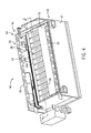
- FIG. 4 is an overhead perspective view of an embodiment of a power assembly of a battery module, in accordance with an aspect of the present disclosure
- FIG. 5 is a cross-sectional perspective view of the battery module of FIG. 4 , taken along line 5 - 5 , in accordance with an aspect of the present disclosure
- FIG. 6 is an expanded view of a portion of the battery module depicted in FIG. 5 along line 6 - 6 , in accordance with an aspect of the present disclosure
- FIG. 7 is a perspective view of an embodiment of a temperature sensing component of the sensing and bus bar assembly of FIG. 4 , in accordance with an aspect of the present disclosure
- FIG. 8 is an expanded perspective view of a portion the battery module of FIG. 6 and depicting the positioning of temperature sensing features relative to heat exchange fins and battery cells of the module, in accordance with an aspect of the present disclosure.
- FIG. 9 is a flow diagram illustrating an embodiment of a method for manufacturing a battery module, in accordance with an aspect of the present disclosure.
- the battery systems described herein may be used to provide power to various types of electric vehicles (xEVs) and other high voltage energy storage/expending applications (e.g., electrical grid power storage systems).
- Such battery systems may include one or more battery modules, each battery module having a number of prismatic battery cells (e.g., lithium-ion (Li-ion) electrochemical cells) arranged to provide particular voltages and/or currents useful to power, for example, one or more components of an xEV.
- prismatic battery cells e.g., lithium-ion (Li-ion) electrochemical cells
- the battery cells may have a variety of shapes and sizes, and the present disclosure is intended to generally apply to all of these variations as appropriate.
- certain types of battery cells having particular shapes such as prismatic battery cells, may be subject to swelling and variations within a particular manufacturing tolerance.
- swelling can result in resistance growth in the cell and contribute to deformities in the battery modules. As such, the useful life span of the battery modules is reduced.
- actuatable clamping mechanisms such as a clamp attached to the battery module, a movable plate disposed within the battery module housing that may be actuated (e.g., using a crank, a clamp, an adjustable tie and bolt mechanism) to abut against the battery cells, or an adjustable tie and bolt mechanism used to actuate components (e.g., outer or inner walls) of the battery module housing, may be used to compress the battery cells by a particular amount. This may be done to maintain the energy density and performance of the battery cells within a predetermined range.
- Prismatic battery cells for example, are traditionally held in place by such actuatable clamping mechanisms that are a part of or integrated with a battery module housing.
- present embodiments include battery module designs where battery cells are individually restrained between fins of a heat exchanger using with a filler material formed from a curable epoxy resin at the time of manufacturing.
- the battery cells may be interleaved with a plurality of fins of the heat exchanger within the battery module packaging, which may provide enhanced surface area for heat conduction to enable heat to be pulled away from the battery cells.
- the disclosed filler material may prevent each of the battery cells from substantially swelling during operation (e.g., swelling beyond a predetermined amount), thereby improving performance of the battery cells over the lifetime of the battery module.
- the disclosed restraining medium e.g., filler material
- the restraining medium may be electrically insulating to prevent current leakages between the battery cells and may be thermally conductive to promote battery cell cooling during operation. Additionally, in certain embodiments, the restraining medium may also provide advantages by acting as a sink for heat and/or gases released during a thermal runaway event.
- FIG. 1 is a perspective view of an embodiment of a vehicle 10 , which may utilize a regenerative braking system.
- a vehicle 10 which may utilize a regenerative braking system.
- the battery system 12 may be placed in a location in the vehicle 10 that would have housed a traditional battery system.
- the vehicle 10 may include the battery system 12 positioned similarly to a lead-acid battery of a typical combustion-engine vehicle (e.g., under the hood of the vehicle 10 ).
- the battery system 12 may be positioned to facilitate managing temperature of the battery system 12 .
- positioning a battery system 12 under the hood of the vehicle 10 may enable an air duct to channel airflow over the battery system 12 and cool the battery system 12 .
- the battery system 12 includes an energy storage component 14 coupled to an ignition system 16 , an alternator 18 , a vehicle console 20 , and optionally to an electric motor 21 .
- the energy storage component 14 may capture/store electrical energy generated in the vehicle 10 and output electrical energy to power electrical devices in the vehicle 10 .
- the battery system 12 may supply power to components of the vehicle's electrical system, which may include radiator cooling fans, climate control systems, electric power steering systems, active suspension systems, auto park systems, electric oil pumps, electric super/turbochargers, electric water pumps, heated windscreen/defrosters, window lift motors, vanity lights, tire pressure monitoring systems, sunroof motor controls, power seats, alarm systems, infotainment systems, navigation features, lane departure warning systems, electric parking brakes, external lights, or any combination thereof.
- the energy storage component 14 supplies power to the vehicle console 20 and the ignition system 16 , which may be used to start (e.g., crank) the internal combustion engine 22 .
- the energy storage component 14 may capture electrical energy generated by the alternator 18 and/or the electric motor 21 .
- the alternator 18 may generate electrical energy while the internal combustion engine 22 is running More specifically, the alternator 18 may convert the mechanical energy produced by the rotation of the internal combustion engine 22 into electrical energy.
- the electric motor 21 may generate electrical energy by converting mechanical energy produced by the movement of the vehicle 10 (e.g., rotation of the wheels) into electrical energy.
- the energy storage component 14 may capture electrical energy generated by the alternator 18 and/or the electric motor 21 during regenerative braking
- the alternator and/or the electric motor 21 are generally referred to herein as a regenerative braking system.
- the energy storage component 14 may be electrically coupled to the vehicle's electric system via a bus 24 .
- the bus 24 may enable the energy storage component 14 to receive electrical energy generated by the alternator 18 and/or the electric motor 21 . Additionally, the bus may enable the energy storage component 14 to output electrical energy to the ignition system 16 and/or the vehicle console 20 . Accordingly, when a 12 volt battery system 12 is used, the bus 24 may carry electrical power typically between 8-18 volts.
- the energy storage component 14 may include multiple battery modules.
- the energy storage component 14 includes a lithium ion (e.g., a first) battery module 25 and a lead-acid (e.g., a second) battery module 26 , which each include one or more battery cells.
- the energy storage component 14 may include any number of battery modules.
- the lithium ion battery module 25 and lead-acid battery module 26 are depicted adjacent to one another, they may be positioned in different areas around the vehicle.
- the lead-acid battery module 26 may be positioned in or about the interior of the vehicle 10 while the lithium ion battery module 25 may be positioned under the hood of the vehicle 10 .
- the energy storage component 14 may include multiple battery modules to utilize multiple different battery chemistries.
- performance of the battery system 12 may be improved since the lithium ion battery chemistry generally has a higher coulombic efficiency and/or a higher power charge acceptance rate (e.g., higher maximum charge current or charge voltage) than the lead-acid battery chemistry. As such, the capture, storage, and/or distribution efficiency of the battery system 12 may be improved.
- the battery system 12 may additionally include a control module 27 .
- the control module 27 may control operations of components in the battery system 12 , such as relays (e.g., switches) within energy storage component 14 , the alternator 18 , and/or the electric motor 21 .
- the control module 27 may regulate amount of electrical energy captured/supplied by each battery module 25 or 26 (e.g., to de-rate and re-rate the battery system 12 ), perform load balancing between the battery modules 25 and 26 , determine a state of charge of each battery module 25 or 26 , determine temperature of each battery module 25 or 26 , control voltage output by the alternator 18 and/or the electric motor 21 , and the like.
- the control module 27 may include one or processor 28 and one or more memory 29 .
- the one or more processor 28 may include one or more application specific integrated circuits (ASICs), one or more field programmable gate arrays (FPGAs), one or more general purpose processors, or any combination thereof.
- the one or more memory 29 may include volatile memory, such as random access memory (RAM), and/or non-volatile memory, such as read-only memory (ROM), optical drives, hard disc drives, or solid-state drives.
- the control module 27 may include portions of a vehicle control unit (VCU) and/or a separate battery control module.
- VCU vehicle control unit
- the lithium ion battery module 25 and the lead-acid battery module 26 are connected in parallel across their terminals. In other words, the lithium ion battery module 25 and the lead-acid module 26 may be coupled in parallel to the vehicle's electrical system via the bus 24 .
- the lithium ion battery modules 25 described herein, as noted, may include a number of lithium ion electrochemical cells (e.g., lithium ion battery cells) electrically coupled to provide particular currents and/or voltages to provide power to the xEV 10 .
- FIG. 3 is a perspective view of an embodiment of a battery cell 30 , in particular a prismatic battery cell, that may be used within the presently disclosed battery module 25 . Again, other battery cell shapes and designs may be incorporated into other similarly-configured battery modules.
- the illustrated battery cell 30 has a packaging 32 (e.g., a metallic or plastic “casing” or “can”) that encloses the internal components of the cell, including cathode and anode materials and a suitable electrolyte.
- the battery cell 30 may be any suitable type of lithium ion electrochemical cell, including but not limited to lithium nickel manganese cobalt oxide (NMC) and lithium titanate (LTO) battery cells, NMC/graphite battery cells, and so forth.
- the positive electrode (cathode) active material and/or the negative electrode (anode) active material may be a lithium metal oxide (LMO) component or a blend of multiple LMO components.
- lithium metal oxides (LMOs) may refer to any class of materials whose formula includes lithium and oxygen as well as one or more additional metal species (e.g., nickel, cobalt, manganese, aluminum, iron, or another suitable metal).
- LMOs may include: mixed metal compositions including lithium, nickel, manganese, and cobalt ions such as lithium nickel cobalt manganese oxide (NMC) (e.g., LiNi x Co y Mn z O 2 ), lithium nickel cobalt aluminum oxide (NCA) (e.g., LiNi x Co y Al z O 2 ), lithium cobalt oxide (LCO) (e.g., LiCoO 2 ), and lithium metal oxide spinel (LMO-spinel) (e.g., LiMn 2 O 4 ).
- NMC lithium nickel cobalt manganese oxide
- NCA lithium nickel cobalt aluminum oxide
- LCO lithium cobalt oxide
- LMO-spinel lithium metal oxide spinel
- the positive electrode (cathode) active material may be include NMC blend and the negative electrode (anode) active material may include LTO for the illustrated battery cell 30 .
- the positive electrode (cathode) active material may include any one or a combination of the lithium metal oxides noted above and the negative electrode (anode) active material may include graphite for the illustrated battery cell 30 .
- the present disclosure is not intended to be limited to a particular combination of cathode and anode active materials and, indeed, is intended to be compatible with any appropriate combination of active materials including cathode and anode active materials that may be subject to swelling.
- the packaging or case 32 of the illustrated prismatic battery cell 30 may have no substantial polarity (is a neutral can), or may have a positive or negative polarity.
- the battery cell 30 illustrated in FIG. 3 is prismatic, where a prismatic battery cell, as defined herein, includes a prismatic case that is generally rectangular in shape.
- the prismatic casing is formed from a relatively inflexible, hard (e.g., metallic or plastic) material.
- a relatively inflexible, hard e.g., metallic or plastic
- certain of the embodiments described below may incorporate pouch cells and/or cylindrical cells in addition to or in lieu of prismatic battery cells.
- each prismatic battery cell 30 includes rounded end portions 34 A and 34 B as well as substantially flat front and back faces 36 A and 36 B.
- each prismatic battery cell 30 may include a top portion 38 A, where a set of cell terminals 40 , 42 (e.g., positive and negative cell terminals) are located.
- One or more cell vents 44 may also be located on the top portion 38 A, or any other suitable location.
- the packaging 32 of the illustrated prismatic battery cell 30 also includes a bottom portion 38 B positioned opposite the top portion 38 A.
- First and second end portions 34 A and 34 B which may be straight or rounded, extend between the bottom and top casing portions 38 A, 38 B in respective positions corresponding to the cell terminals 40 , 42 .
- Front and back faces 36 A, 36 B which may be flat (as shown) or may include other geometric features, couple the first and second end portions 34 A, 34 B at opposing ends of the packaging 32 of the illustrated prismatic battery cell 30 .
- the illustrated prismatic battery cell 30 may swell or expand during operation.
- the prismatic battery cell 30 is a lithium ion battery cell having a graphitic anode active material (e.g., or layers of a “coil” disposed within the packaging 32 of the prismatic battery cell 30 )
- the coil may expand as a result of Li intercalation during charging.
- the prismatic battery cell 30 may also expand as a result of resistive heating when charging.
- the packaging 32 of the prismatic battery cell 30 if the packaging 32 of the prismatic battery cell 30 is not properly restrained, then the packaging 32 may bulge and swell as a result of the expansion of the internal components of the cell.
- the prismatic battery cell 30 This reduces energy density and performance of the battery cell 30 .
- the individual cathode and anode layers of the “coil” may be allowed to separate from one another (e.g., de-laminate), increasing the resistance of the battery cell 30 .
- FIG. 4 is a perspective view illustrating a non-limiting example of the manner in which the prismatic battery cells 30 may be arranged within a housing 47 of the battery module 25 .
- the illustrated battery module 25 includes a power assembly 48 including a plurality of prismatic battery cells 30 electrically coupled to one another via first bus bars 50 and second bus bars 52 . More specifically, the first bus bars 50 are positioned on a first carrier 54 over the terminals 40 , 42 (see FIG.
- Each prismatic battery cell 30 may be oriented electrically opposite the adjacent prismatic battery cell 30 , such that the negative terminals 42 of the prismatic battery cells 30 are disposed near the positive terminals 40 of the neighboring prismatic battery cell 30 .
- the first and second bus bars 50 , 52 electrically couple the positive terminal of one prismatic battery cell (e.g., the positive terminal 40 of the prismatic battery cell 30 ) to the negative terminal of an adjacent prismatic battery cell (e.g., the negative terminal 42 of the prismatic battery cell 30 ).
- each of the terminals of the prismatic battery cells 30 of the power assembly 48 would be coupled to one of the first or second bus bars 50 , 52 , except for the battery cells 30 at either end of the power assembly, which may be electrically coupled other portions (e.g., a master relay, power conversion circuitry) of the battery module 25 .
- the front and back faces 36 A, 36 B may be substantially parallel to the front and back end portions 34 A, 34 B of an adjacent prismatic battery cell 30 .
- the bus bar carriers 54 , 58 may be polymeric and the bus bars 50 , 52 may be monometallic or bimetallic. That is, for embodiments in which the prismatic battery cells 30 include an embodiment of the positive terminal 40 made from a first metal (e.g., aluminum) and an embodiment of the negative terminal 42 made from a second metal (e.g., copper), a portion of each bus bar 50 , 52 may be made from the first metal (e.g., aluminum), and another portion may be made from the second metal (e.g., copper) to enable effective laser welding and mitigate galvanic effects.
- the bus bars 50 , 52 may also include other materials, such as coatings, to facilitate welding (e.g., laser welding) to electrically couple the battery cells 30 to their terminals 40 , 42 .
- the first bus bars 50 and the first carrier 54 may be considered to be a part of a sensing and bus bar assembly 64 , which may include features (e.g., bus bars 50 ) configured to electrically couple the battery cells 30 and other features configured to sense, for example, a temperature of the battery cells 30 (e.g., during operation of the battery module 25 ).
- the sensing and bus bar assembly 64 includes sense lines 65 (e.g., voltage sense lines 66 ) connected to the first bus bars 50 to enable the control module 27 (see FIG. 2 ) to monitor a voltage across the battery cells 30 . Such monitoring may enable the control module 27 to control the operation of the battery module 25 for voltage output, temperature control, or similar purposes.
- the illustrated sensing and bus bar assembly 64 also includes certain temperature sensing features, which are described in further detail below with respect to FIGS. 8 and 9 .
- FIG. 5 is a cross-sectional perspective view of the battery module 25 of FIG. 4 taken along line 5 - 5 .
- a plurality of prismatic battery cells 30 positioned within the housing 47 are fixed between a plurality of heat exchanger fins 68 of a heat sink 70 .
- the heat exchanger fins 68 and the battery cells 30 are interleaved (e.g., alternating).
- the heat sink 70 may be disposed on a bottom 72 of the housing 47 .
- the heat exchanger fins 68 may be substantially parallel to the front and back faces 36 A, 36 B of the prismatic battery cells 30 , which may enable improved heat exchange compared to other relative positions.
- the illustrated battery module 25 also includes other compartments, including one or more compartments 74 configured to house other components (e.g., relays, control circuitry) of the battery module 25 separately from the battery cells 30 and from a filler material 76 restraining the cells 30 in the housing 47 .
- the filler material 76 covers the heat exchanger fins 68 and portions of the battery cells 30 .
- the filler material 76 may contact a portion of the front and back faces 36 A, 36 B.
- the filler material 76 may also contact portions of the heat sink 70 that are substantially perpendicular to the front and back faces 36 A, 36 B of the prismatic battery cells 30 .
- the filler material 76 may conform to all of the surfaces it contacts, enabling enhanced heat transfer between the filler material 76 and certain thermally conductive components (e.g., the heat exchanger fins 68 and the battery cells 30 ).
- the filler material 76 may also absorb some of the heat produced by the battery cells 30 .
- the filler material 76 may have a substantially uniform thermal conductivity in all directions.
- the thermal conductivity value of the filler material 76 may be between approximately 0.5 Watts per meter Kelvin (W/m-K) and approximately 1.5 W/m-K.
- the heat exchanger fins 68 provide more surface area for the heat produced by the prismatic battery cells 30 to be dispersed to.
- the fins 68 may transfer heat (e.g., through conduction) from the prismatic battery cells 30 downwards to the heat sink 70 , as described further in FIG. 6 .
- FIG. 6 is an expanded view of a portion of the battery module 25 depicted in FIG. 5 along line 6 - 6 , in accordance with an aspect of the present disclosure.
- the filler material 76 provides a thermally conductive pathway between the prismatic battery cells 30 and the heat exchanger fins 68 . As such, heat produced from the prismatic battery cells 30 may be dissipated as heat from the hot battery cells 30 flows (e.g., as shown by arrow 77 ) to a cooler surface of the heat exchanger fins 68 .
- the front and back faces 36 A, 36 B (e.g., an interface surface) of the cells 30 extend between the top portion 38 A and the bottom portion 38 B of the cells 30 .
- the filler material 76 may completely cover the heat exchanger fins 68 and a portion of the prismatic battery cells 30 .
- the filler material 76 may cover the bottom portion 38 B of the battery cells 30 .
- the filler material 76 may cover approximately 60%, 65%, 70%, 75%, 80%, 85%, to 90% of a longitudinal distance 80 of the side portions 36 A, 36 B of the battery cells 30 .
- Covering the side portions 36 A, 36 B of the battery cells 30 improves restraint of the battery cells 30 within the battery module housing 47 and provides a thermal conduction path from the first and second lithium ion battery cells 30 to the heat exchanger plate coupled to the plurality of heat exchanger fins 68 .
- the top portion 38 A of each of the battery cells 30 may protrude beyond a free end 82 (e.g., distal end from the heat exchanger plate) of the fin 68 along the longitudinal distance 80 of the battery cells 30 .
- the filler material 76 may also cover a portion of the heat sink 70 .
- the filler material 76 may also contact portions of the heat sink 70 that are substantially perpendicular to the front and back faces 36 A, 36 B of the prismatic battery cells 30 .
- the heat exchanger fins 68 depicted are substantially straight, the heat exchanger fins 68 may be tapered, or have different geometries. All or a portion of the heat exchanger fins 68 , whether substantially straight, tapered, or with varying geometries, may be covered with the filler material 76 , as described further with respect to FIG. 8 .
- the heat exchanger fins 68 may be coupled to temperature sensing components 84 disposed in the bus bar assembly 64 (see FIG. 4 ) to provide temperature readings to a control module 27 .
- FIG. 7 is a perspective view of an embodiment of temperature sensing components 84 of the sensing and bus bar assembly 64 of FIG. 4 , in accordance with an aspect of the present disclosure.
- a sensing circuit assembly 93 of the bus bar assembly 64 which may be a flexible circuit including the temperature sensing components 84 and the voltage sense lines 66 , are also depicted.
- the plurality of temperature sensing components 84 may be surface mount devices configured to monitor the temperature of the fins 68 (see FIG. 6 ).
- the temperature sensing components 84 may be communicatively coupled to the control module 27 (see FIG. 2 ).
- the control module may be same control module 27 that controls operations of components in the battery system 12 , such as relays (e.g., switches) within energy storage component 14 , the alternator 18 , and/or the electric motor 21 .
- the control module may be different than the control module 27 that controls other components (e.g., electric motor 21 ). In either case, the control module 27 may regulate amount of electrical energy captured/supplied by the battery module 25 based at least in part on the temperatures sensed by the temperature sensing components 84 .
- the temperature sensing components 84 may be coupled to the plurality of sense lines 65 (e.g., the voltage sense lines 66 or temperature sense lines 67 ) disposed on the carrier bar 58 (see FIG. 4 ).
- the voltage sense lines 66 may carry current and/or voltage signals to the control module 27 .
- the plurality of temperature sensing lines 67 may provide the temperature reading of the temperature sensing components 84 to the control module 27 .
- the sense lines 65 may be coupled to the carrier bar 58 and/or one or more bus bars 50 , 52 via welding (e.g., ultrasonic welding) or in other suitable manners.
- a plurality of solder pads 94 are also provided that couple to the bus bars 50 , 52 .
- solder pads 94 are meant to bond to a copper side of the bus bar 50 , 52 .
- the solder pads 94 are coupled to the voltage sense lines 66 disposed on sensing circuit assembly 93 .
- End connectors 88 (a first end connector 90 , a second end connector 92 ) may be coupled to other components, such as to a board connector.
- FIG. 8 is an expanded perspective view of a portion the battery module 25 of FIG. 6 and depicting the positioning of temperature sensing features 84 relative to heat exchange fins 68 and battery cells 30 of the module, in accordance with an aspect of the present disclosure.
- Disposed on the carrier bars 54 , 58 are the plurality of temperature sense lines 67 . Again, the temperature sensing lines 67 extend from the temperature sensing component 84 to communicate the temperature readings of the battery module 25 to the control module 27 .
- the top portion 38 A of the battery cells 30 remains uncovered by the epoxy resin.
- the epoxy resin may act as a restraining medium in accordance with the present embodiments and may prevent, reduce, or mitigate swelling. It may be appreciated that, by conforming around the shape of each prismatic battery cell 30 , the epoxy resin may provide more uniform contact around each prismatic battery cell 30 despite any defects or imperfections associated with manufacturing variability of each prismatic battery cell 30 .
- the terms “conformal” and “conformally coated” should not be confused with a flexible and conformable material.
- the conformal nature of the epoxy resin is intended to denote the ability of the epoxy resin to be conformed about the prismatic battery cells 30 before it is set, so that the restraining medium is, in a sense, molded about the prismatic battery cells 30 .
- the epoxy resin may contact every side or face of the packaging 32 of the prismatic battery cells 30 except the side of the packaging 32 that includes the vent feature 44 (e.g., contact sides 36 A, 36 B, 34 A, 34 B, 38 B, but not side 38 A, as illustrated in FIG. 3 ) and terminals 40 , 42 .
- the temperature sensing components 84 may be positioned (e.g., hand fit) appropriately to align with and couple to the heat exchanger fins 68 when the carrier bar 58 is positioned over the battery module housing 47 .
- the user may bend the temperature sensing component 84 (e.g., the surface mount device) so that the temperature sensing component 84 is disposed between the battery modules 30 and in contact with the designated heat exchanger fin 68 .
- the temperature sensing component 84 may be disposed between the side portions 36 A, 36 B of the battery cells 30 .
- the distance the temperature sensing component 84 is disposed between the side portions 36 A, 36 B may vary along the longitudinal distance 80 .
- the distance the temperature sensing component 84 extends between the battery cells 30 may depend in part on the height of the heat exchanger fin 68 .
- the temperature sensing component 84 may extend far enough between the battery cells to be in contact with the free end 82 (e.g., distal end from the heat exchanger plate) of the heat exchanger fin 68 .
- the position of the temperature sensing component 84 may be fixed by positioning the carrier bar 58 such that the temperature sensing component 84 is located in the space between the battery cells 30 .
- the epoxy resin may be electrically insulating, especially when the packaging 32 of the prismatic battery cells 30 has a positive or negative polarity; however, an electrically insulating epoxy resin may still be useful to limit leakage currents between prismatic battery cells 30 having neutral packaging 32 .
- the epoxy resin may be thermally conductive. It may be appreciated that using a conformal epoxy resin ensures that the restraining medium is in good thermal contact with a substantial portion of the surface of the packaging 32 of each prismatic battery cell 30 and with the battery module packaging 47 , which may improve thermal transfer between the prismatic battery cells 30 and the aforementioned heat sink feature.
- the epoxy resin may also be useful to absorb gases (e.g., CO 2 ) and heat that may be released if one or more of the prismatic battery cells 30 undergoes a thermal event.
- the epoxy resin may include a binary epoxy and/or a thermal epoxy and may include one or more additives to provide the above-mentioned properties.
- the epoxy resin may be impregnated with metal (e.g., aluminum powder) or carbon particles to enhance thermal conductivity of the epoxy resin.
- the epoxy resin may be formed from one or more restraining medium precursor materials that may solidify upon curing.
- the epoxy resin may be formed from a two-part epoxy resin that only begins to solidify after both parts have been mixed together.
- one or more restraining medium precursor materials may cure and solidify in response to heat, light, or mixing time.
- the epoxy resin precursor may be a liquid, solid, gel, powder, pellets, or a suitable compressed material (e.g., ceramic) that may be formed via curing, cross-linking, sintering, finishing, or another suitable solidification or finishing method.
- a suitable compressed material e.g., ceramic
- FIG. 9 is a flow diagram illustrating an embodiment of a method for manufacturing a battery module 25 of the present approach.
- FIG. 9 illustrates an embodiment of a method 100 of manufacturing a battery module that includes adding (block 102 ) a heat exchanger to the battery module housing 47 . Then, the battery cells 30 are positioned on either side of a fin 68 of the heat exchanger (block 104 ). Next, the temperature sensing components 84 are positioned proximate the free end of the fin 68 of the heat exchanger (block 106 ).
- the battery module housing 47 is then filled (block 108 ) with a filler material 76 to cover the fin 68 of the heat exchanger and the temperature sensing component 84 .
- the prismatic battery cells 30 are attached (block 110 ) to the bus bars 50 and 52 , for example, using laser welding to weld the terminals 40 , 42 of the prismatic battery cells 30 to the bus bars 50 , 52 of the bus bar assemblies 64 .
- the filler material 76 may be cured (block 112 ) to form the cured battery module 25 .
- the curing (or other finishing/hardening step) results in the formation of a restraint system and thermal conduction path, and individually secures and restrains each prismatic battery cell 30 of the battery module 25 .
- other components of the battery module 25 e.g., relays, control circuitry
- the technical effects of the present disclosure include the manufacture of battery modules having individually restrained battery cells.
- the disclosed designs enable the use of an epoxy resin disposed over a plurality of heat exchanger fins disposed in a housing of battery module to individually restrain the battery cells into position upon curing of the epoxy resin.
- the disclosed restraining medium individually prevents each of the battery cells from substantially swelling during operation, improving performance of the battery cells over the lifetime of the battery module. Further, the restraining medium may electrically insulate the battery cells, as well as promote battery cell cooling during operation of the battery module. Accordingly, the disclosed battery module designs offer improved flexibility and performance compared to other battery module designs.
Abstract
Description
Claims (21)
Priority Applications (4)
| Application Number | Priority Date | Filing Date | Title |
|---|---|---|---|
| US14/805,404 US10199695B2 (en) | 2014-08-18 | 2015-07-21 | Battery module with restrained battery cells utilizing a heat exchanger |
| PCT/US2015/045178 WO2016028616A1 (en) | 2014-08-18 | 2015-08-14 | Battery module with restrained battery cells utilizing a heat exchanger |
| CN201580047810.5A CN107004792B (en) | 2014-08-18 | 2015-08-14 | Battery module with restraining battery unit using heat exchanger |
| EP15753857.0A EP3195402B1 (en) | 2014-08-18 | 2015-08-14 | Battery module with restrained battery cells utilizing a heat exchanger |
Applications Claiming Priority (2)
| Application Number | Priority Date | Filing Date | Title |
|---|---|---|---|
| US201462038664P | 2014-08-18 | 2014-08-18 | |
| US14/805,404 US10199695B2 (en) | 2014-08-18 | 2015-07-21 | Battery module with restrained battery cells utilizing a heat exchanger |
Publications (2)
| Publication Number | Publication Date |
|---|---|
| US20160049703A1 US20160049703A1 (en) | 2016-02-18 |
| US10199695B2 true US10199695B2 (en) | 2019-02-05 |
Family
ID=55302828
Family Applications (1)
| Application Number | Title | Priority Date | Filing Date |
|---|---|---|---|
| US14/805,404 Active 2036-04-11 US10199695B2 (en) | 2014-08-18 | 2015-07-21 | Battery module with restrained battery cells utilizing a heat exchanger |
Country Status (4)
| Country | Link |
|---|---|
| US (1) | US10199695B2 (en) |
| EP (1) | EP3195402B1 (en) |
| CN (1) | CN107004792B (en) |
| WO (1) | WO2016028616A1 (en) |
Cited By (1)
| Publication number | Priority date | Publication date | Assignee | Title |
|---|---|---|---|---|
| US11139516B2 (en) | 2019-05-06 | 2021-10-05 | Bae Systems Controls Inc. | Battery cell module |
Families Citing this family (15)
| Publication number | Priority date | Publication date | Assignee | Title |
|---|---|---|---|---|
| US9692031B2 (en) * | 2015-04-09 | 2017-06-27 | Ford Global Technologies, Llc | Bus bar assembly for electrified vehicle batteries |
| FI129718B (en) * | 2016-05-19 | 2022-07-29 | Valmet Automotive Oy | A battery module, components and a method |
| CN109478618B (en) * | 2016-07-27 | 2021-11-23 | 柯锐世先进解决方案有限责任公司 | Battery cell assembly for battery module |
| US20180294536A1 (en) * | 2017-03-27 | 2018-10-11 | Martin Kruszelnicki | Battery pack module |
| US10637105B2 (en) * | 2017-09-07 | 2020-04-28 | International Business Machines Corporation | Battery embedded architecture for supplying appropriate voltage |
| US10615396B2 (en) | 2017-09-08 | 2020-04-07 | Molex, Llc | Battery connection module |
| TW201914086A (en) * | 2017-09-08 | 2019-04-01 | 莫仕有限公司 | Battery connection module |
| US11309597B2 (en) * | 2018-01-11 | 2022-04-19 | Carrier Corporation | Battery temperature control |
| EP3518312A1 (en) * | 2018-01-24 | 2019-07-31 | Samsung SDI Co., Ltd. | Battery module comprising a housing with integrated bus bar |
| EP3678215A1 (en) * | 2019-01-07 | 2020-07-08 | Andreas Stihl AG & Co. KG | Cell connector structure, battery pack and gardening and/or forestry system |
| EP3678216B1 (en) | 2019-01-07 | 2022-08-17 | Andreas Stihl AG & Co. KG | Battery pack and gardening and/or forestry system |
| KR102439229B1 (en) * | 2019-06-12 | 2022-08-31 | 주식회사 엘지에너지솔루션 | Battery module, method for preparing the same and battery pack including the same |
| CN111769217A (en) * | 2020-07-10 | 2020-10-13 | 梅州市博富能科技有限公司 | High-power discharge lithium battery |
| DE102021105833B4 (en) * | 2021-03-10 | 2022-09-29 | Dr. Ing. H.C. F. Porsche Aktiengesellschaft | battery module |
| CN115172961B (en) * | 2022-07-13 | 2023-11-24 | 湖北省电力装备有限公司 | Compact lithium battery energy storage container |
Citations (44)
| Publication number | Priority date | Publication date | Assignee | Title |
|---|---|---|---|---|
| JPH08321329A (en) | 1995-05-26 | 1996-12-03 | Sanyo Electric Co Ltd | Battery |
| US5786107A (en) | 1996-05-09 | 1998-07-28 | Hughes Electronics | Battery system with a high-thermal-conductivity integral structural support |
| US6821671B2 (en) | 2002-03-01 | 2004-11-23 | Lg Chem, Ltd. | Method and apparatus for cooling and positioning prismatic battery cells |
| US7241530B2 (en) | 2002-07-23 | 2007-07-10 | Nissan Motor Co., Ltd. | Module battery |
| KR20080032748A (en) | 2006-10-10 | 2008-04-16 | 현대에너셀 주식회사 | Electric cell module having radiant heat plate |
| US20080090137A1 (en) * | 2006-10-13 | 2008-04-17 | Derrick Scott Buck | Battery pack with integral cooling and bussing devices |
| CN201262974Y (en) | 2008-08-18 | 2009-06-24 | 东莞新能源科技有限公司 | Lithium ion battery stack |
| DE102007063179A1 (en) | 2007-12-20 | 2009-06-25 | Daimler Ag | Battery as a flat cell assembly with a heat conducting plate |
| JP2009272048A (en) | 2008-04-30 | 2009-11-19 | Hitachi Vehicle Energy Ltd | Battery module |
| EP2178135A1 (en) | 2008-10-08 | 2010-04-21 | Samsung SDI Co., Ltd. | Rechargeable battery, assembly comprising such a battery and battery module |
| US20100108140A1 (en) | 2008-03-14 | 2010-05-06 | E. I. Du Pont De Nemours And Company | Device capable of thermally cooling while electrically insulating |
| US20110059347A1 (en) | 2009-04-01 | 2011-03-10 | Lg Chem, Ltd. | Battery module having excellent heat dissipation ability and battery pack employed with the same |
| US20110223461A1 (en) | 2010-03-09 | 2011-09-15 | Samsung Sdi Co., Ltd. | Secondary battery |
| US20110244299A1 (en) | 2008-12-10 | 2011-10-06 | Nevzat Guener | Energy Store |
| US20110293982A1 (en) | 2010-05-28 | 2011-12-01 | Gm Global Technology Operations, Inc. | Corrugated fin and frame assembly for battery cooling |
| US20120009455A1 (en) | 2010-07-06 | 2012-01-12 | Ji-Hyoung Yoon | Battery Module |
| EP2418710A1 (en) | 2010-08-10 | 2012-02-15 | SB LiMotive Co., Ltd. | Battery module |
| GB2483079A (en) | 2010-08-25 | 2012-02-29 | Lightning Car Company Ltd | Battery Module |
| US20120088135A1 (en) * | 2009-09-15 | 2012-04-12 | Lg Chem, Ltd. | Battery module having temperature sensor and battery pack employed with the same |
| US20120107649A1 (en) | 2010-10-27 | 2012-05-03 | GM Global Technology Operations LLC | Battery thermal system with interlocking strucure components |
| US20120219839A1 (en) | 2009-11-11 | 2012-08-30 | Carl Freudenberg Kg | Mechanically flexible and porous compensating element for controlling the temperature of electrochemical cells |
| WO2012125115A1 (en) | 2011-03-15 | 2012-09-20 | Effpower Ab | Battery module, vehicle, electric device and method |
| US8323819B2 (en) | 2009-07-27 | 2012-12-04 | Lg Chem, Ltd. | Battery module of improved cooling efficiency |
| US20120315519A1 (en) | 2011-06-10 | 2012-12-13 | Hee-Joon Jin | Battery module |
| US8343648B2 (en) | 2007-03-05 | 2013-01-01 | Temic Automotive Electric Motors Gmbh | Power storage cell with heat conducting plate |
| WO2013009750A2 (en) | 2011-07-11 | 2013-01-17 | California Institute Of Technology | Novel separators for electrochemical systems |
| US8367239B2 (en) * | 2009-08-21 | 2013-02-05 | Tesla Motors, Inc. | Cell separator for minimizing thermal runaway propagation within a battery pack |
| DE102011081149A1 (en) | 2011-08-17 | 2013-02-21 | Sgl Carbon Se | Heat sink and electrical energy storage |
| JP2013051099A (en) | 2011-08-31 | 2013-03-14 | Nissan Motor Co Ltd | Module for battery temperature control |
| US20130122330A1 (en) * | 2010-07-23 | 2013-05-16 | Evonik Degussa Gmbh | Lithium cells and batteries with improved stability and safety, method for the production thereof, and application in mobile and stationary electrical energy accumulators |
| EP2608310A2 (en) | 2010-08-16 | 2013-06-26 | LG Chem, Ltd. | Battery module with compact structure and excellent heat radiation characteristics, and medium- or large-sized battery pack |
| US20130164578A1 (en) | 2011-12-21 | 2013-06-27 | Edward Thomas Sweet | Battery module |
| US20130202924A1 (en) | 2012-02-08 | 2013-08-08 | Hyundai Motor Company | Radiant heat plate for battery cell module and battery cell module having the same |
| US20130202939A1 (en) | 2012-02-08 | 2013-08-08 | Hyundai Motor Company | Heat control pouch for battery cell module and battery cell module having the same |
| US20130209856A1 (en) | 2012-02-15 | 2013-08-15 | GM Global Technology Operations LLC | Cooling system for automotive battery |
| US20130266837A1 (en) | 2012-04-04 | 2013-10-10 | Hyundai Motor Company | Heat radiation plate for battery module and battery module having the same |
| EP2340583B1 (en) | 2008-09-18 | 2013-11-06 | MAGNA STEYR Battery Systems GmbH & Co OG | Cooling unit |
| US20130302659A1 (en) | 2009-10-19 | 2013-11-14 | Nitto Denko Corporation | Thermally conductive member, and battery device using the same |
| US20130323564A1 (en) | 2012-06-04 | 2013-12-05 | Graftech International Holdings Inc. | Battery Pack Assembly |
| US20140030561A1 (en) | 2007-11-09 | 2014-01-30 | Lg Chem, Ltd. | Battery module of excellent heat dissipation property and heat exchange member |
| WO2014025869A1 (en) | 2012-08-07 | 2014-02-13 | Waters John E | Battery module construction |
| US8652678B2 (en) | 2012-04-17 | 2014-02-18 | Vecture Inc. | Battery pack system |
| US20140093766A1 (en) | 2011-05-28 | 2014-04-03 | Audi Ag | Battery for a vehicle and method for producing a battery |
| US9123944B2 (en) * | 2010-03-25 | 2015-09-01 | Ford Global Technologies, Llc | Battery cover assembly |
Family Cites Families (1)
| Publication number | Priority date | Publication date | Assignee | Title |
|---|---|---|---|---|
| WO2013080512A1 (en) * | 2011-11-30 | 2013-06-06 | 株式会社ヴァレオジャパン | Battery temperature control unit |
-
2015
- 2015-07-21 US US14/805,404 patent/US10199695B2/en active Active
- 2015-08-14 CN CN201580047810.5A patent/CN107004792B/en active Active
- 2015-08-14 EP EP15753857.0A patent/EP3195402B1/en active Active
- 2015-08-14 WO PCT/US2015/045178 patent/WO2016028616A1/en active Application Filing
Patent Citations (48)
| Publication number | Priority date | Publication date | Assignee | Title |
|---|---|---|---|---|
| JPH08321329A (en) | 1995-05-26 | 1996-12-03 | Sanyo Electric Co Ltd | Battery |
| US5786107A (en) | 1996-05-09 | 1998-07-28 | Hughes Electronics | Battery system with a high-thermal-conductivity integral structural support |
| US6821671B2 (en) | 2002-03-01 | 2004-11-23 | Lg Chem, Ltd. | Method and apparatus for cooling and positioning prismatic battery cells |
| US7241530B2 (en) | 2002-07-23 | 2007-07-10 | Nissan Motor Co., Ltd. | Module battery |
| KR20080032748A (en) | 2006-10-10 | 2008-04-16 | 현대에너셀 주식회사 | Electric cell module having radiant heat plate |
| US20080090137A1 (en) * | 2006-10-13 | 2008-04-17 | Derrick Scott Buck | Battery pack with integral cooling and bussing devices |
| US8343648B2 (en) | 2007-03-05 | 2013-01-01 | Temic Automotive Electric Motors Gmbh | Power storage cell with heat conducting plate |
| US20140030561A1 (en) | 2007-11-09 | 2014-01-30 | Lg Chem, Ltd. | Battery module of excellent heat dissipation property and heat exchange member |
| DE102007063179A1 (en) | 2007-12-20 | 2009-06-25 | Daimler Ag | Battery as a flat cell assembly with a heat conducting plate |
| US20100108140A1 (en) | 2008-03-14 | 2010-05-06 | E. I. Du Pont De Nemours And Company | Device capable of thermally cooling while electrically insulating |
| JP2009272048A (en) | 2008-04-30 | 2009-11-19 | Hitachi Vehicle Energy Ltd | Battery module |
| CN201262974Y (en) | 2008-08-18 | 2009-06-24 | 东莞新能源科技有限公司 | Lithium ion battery stack |
| EP2340583B1 (en) | 2008-09-18 | 2013-11-06 | MAGNA STEYR Battery Systems GmbH & Co OG | Cooling unit |
| EP2178135A1 (en) | 2008-10-08 | 2010-04-21 | Samsung SDI Co., Ltd. | Rechargeable battery, assembly comprising such a battery and battery module |
| US20110244299A1 (en) | 2008-12-10 | 2011-10-06 | Nevzat Guener | Energy Store |
| US20110059347A1 (en) | 2009-04-01 | 2011-03-10 | Lg Chem, Ltd. | Battery module having excellent heat dissipation ability and battery pack employed with the same |
| US8323819B2 (en) | 2009-07-27 | 2012-12-04 | Lg Chem, Ltd. | Battery module of improved cooling efficiency |
| US8367239B2 (en) * | 2009-08-21 | 2013-02-05 | Tesla Motors, Inc. | Cell separator for minimizing thermal runaway propagation within a battery pack |
| US8481191B2 (en) | 2009-08-21 | 2013-07-09 | Tesla Motors, Inc. | Rigid cell separator for minimizing thermal runaway propagation within a battery pack |
| US20120088135A1 (en) * | 2009-09-15 | 2012-04-12 | Lg Chem, Ltd. | Battery module having temperature sensor and battery pack employed with the same |
| US20130302659A1 (en) | 2009-10-19 | 2013-11-14 | Nitto Denko Corporation | Thermally conductive member, and battery device using the same |
| US8597812B2 (en) | 2009-10-19 | 2013-12-03 | Nitto Denko Corporation | Thermally conductive member and battery pack device using same |
| US20120219839A1 (en) | 2009-11-11 | 2012-08-30 | Carl Freudenberg Kg | Mechanically flexible and porous compensating element for controlling the temperature of electrochemical cells |
| US20110223461A1 (en) | 2010-03-09 | 2011-09-15 | Samsung Sdi Co., Ltd. | Secondary battery |
| US9123944B2 (en) * | 2010-03-25 | 2015-09-01 | Ford Global Technologies, Llc | Battery cover assembly |
| US20110293982A1 (en) | 2010-05-28 | 2011-12-01 | Gm Global Technology Operations, Inc. | Corrugated fin and frame assembly for battery cooling |
| US20120009455A1 (en) | 2010-07-06 | 2012-01-12 | Ji-Hyoung Yoon | Battery Module |
| US20130122330A1 (en) * | 2010-07-23 | 2013-05-16 | Evonik Degussa Gmbh | Lithium cells and batteries with improved stability and safety, method for the production thereof, and application in mobile and stationary electrical energy accumulators |
| EP2418710A1 (en) | 2010-08-10 | 2012-02-15 | SB LiMotive Co., Ltd. | Battery module |
| US20120040226A1 (en) | 2010-08-10 | 2012-02-16 | Myung-Chul Kim | Battery Module |
| EP2608310A2 (en) | 2010-08-16 | 2013-06-26 | LG Chem, Ltd. | Battery module with compact structure and excellent heat radiation characteristics, and medium- or large-sized battery pack |
| GB2483079A (en) | 2010-08-25 | 2012-02-29 | Lightning Car Company Ltd | Battery Module |
| US20120107649A1 (en) | 2010-10-27 | 2012-05-03 | GM Global Technology Operations LLC | Battery thermal system with interlocking strucure components |
| WO2012125115A1 (en) | 2011-03-15 | 2012-09-20 | Effpower Ab | Battery module, vehicle, electric device and method |
| US20140093766A1 (en) | 2011-05-28 | 2014-04-03 | Audi Ag | Battery for a vehicle and method for producing a battery |
| US20120315519A1 (en) | 2011-06-10 | 2012-12-13 | Hee-Joon Jin | Battery module |
| WO2013009750A2 (en) | 2011-07-11 | 2013-01-17 | California Institute Of Technology | Novel separators for electrochemical systems |
| DE102011081149A1 (en) | 2011-08-17 | 2013-02-21 | Sgl Carbon Se | Heat sink and electrical energy storage |
| JP2013051099A (en) | 2011-08-31 | 2013-03-14 | Nissan Motor Co Ltd | Module for battery temperature control |
| US20130164578A1 (en) | 2011-12-21 | 2013-06-27 | Edward Thomas Sweet | Battery module |
| KR20130091506A (en) | 2012-02-08 | 2013-08-19 | 현대자동차주식회사 | Radiant heat plate for battery cell module and battery cell module having the same |
| US20130202939A1 (en) | 2012-02-08 | 2013-08-08 | Hyundai Motor Company | Heat control pouch for battery cell module and battery cell module having the same |
| US20130202924A1 (en) | 2012-02-08 | 2013-08-08 | Hyundai Motor Company | Radiant heat plate for battery cell module and battery cell module having the same |
| US20130209856A1 (en) | 2012-02-15 | 2013-08-15 | GM Global Technology Operations LLC | Cooling system for automotive battery |
| US20130266837A1 (en) | 2012-04-04 | 2013-10-10 | Hyundai Motor Company | Heat radiation plate for battery module and battery module having the same |
| US8652678B2 (en) | 2012-04-17 | 2014-02-18 | Vecture Inc. | Battery pack system |
| US20130323564A1 (en) | 2012-06-04 | 2013-12-05 | Graftech International Holdings Inc. | Battery Pack Assembly |
| WO2014025869A1 (en) | 2012-08-07 | 2014-02-13 | Waters John E | Battery module construction |
Non-Patent Citations (1)
| Title |
|---|
| PCT/US2015/045178 International Search Report and Written Opinion dated Oct. 29, 2015. |
Cited By (1)
| Publication number | Priority date | Publication date | Assignee | Title |
|---|---|---|---|---|
| US11139516B2 (en) | 2019-05-06 | 2021-10-05 | Bae Systems Controls Inc. | Battery cell module |
Also Published As
| Publication number | Publication date |
|---|---|
| US20160049703A1 (en) | 2016-02-18 |
| EP3195402B1 (en) | 2018-08-08 |
| EP3195402A1 (en) | 2017-07-26 |
| CN107004792A (en) | 2017-08-01 |
| CN107004792B (en) | 2020-09-01 |
| WO2016028616A1 (en) | 2016-02-25 |
Similar Documents
| Publication | Publication Date | Title |
|---|---|---|
| US10199695B2 (en) | Battery module with restrained battery cells utilizing a heat exchanger | |
| US11881552B2 (en) | Cell to heat sink thermal adhesive | |
| US9620764B2 (en) | Battery module cooling fins and footings system and method | |
| EP3491686B1 (en) | Cell assembly for a battery module | |
| EP3201969B1 (en) | Battery module passive thermal management features and positioning | |
| US20160093851A1 (en) | Battery module with individually restrained battery cells | |
| EP3201975B1 (en) | Battery module bus bar connection assembly | |
| US20160268643A1 (en) | Battery module separator plates | |
| US20160336578A1 (en) | Features for preventing short circuit in a battery module | |
| WO2019010323A1 (en) | Single piece current collector for battery cell | |
| EP3243239B1 (en) | Battery module cooling fins and footings system |
Legal Events
| Date | Code | Title | Description |
|---|---|---|---|
| AS | Assignment |
Owner name: JOHNSON CONTROLS TECHNOLOGY COMPANY, MICHIGAN Free format text: ASSIGNMENT OF ASSIGNORS INTEREST;ASSIGNORS:LOBERT, JONATHAN P.;TYLER, MATTHEW R.;ZHANG, XUGANG;SIGNING DATES FROM 20150720 TO 20150721;REEL/FRAME:036156/0613 |
|
| STCF | Information on status: patent grant |
Free format text: PATENTED CASE |
|
| CC | Certificate of correction | ||
| AS | Assignment |
Owner name: CPS TECHNOLOGY HOLDINGS LLC, NEW YORK Free format text: ASSIGNMENT OF ASSIGNORS INTEREST;ASSIGNOR:JOHNSON CONTROLS TECHNOLOGY COMPANY;REEL/FRAME:049551/0672 Effective date: 20190430 |
|
| AS | Assignment |
Owner name: CITIBANK N.A., AS COLLATERAL AGENT, NEW YORK Free format text: ABL PATENT SECURITY AGREEMENT;ASSIGNOR:CPS TECHNOLOGY HOLDINGS LLC;REEL/FRAME:050229/0079 Effective date: 20190827 Owner name: CITIBANK N.A., AS COLLATERAL AGENT, DELAWARE Free format text: FIRST LIEN PATENT SECURITY AGREEMENT;ASSIGNOR:CPS TECHNOLOGY HOLDINGS LLC;REEL/FRAME:050229/0029 Effective date: 20190827 |
|
| AS | Assignment |
Owner name: CPS TECHNOLOGY HOLDINGS LLC, NEW YORK Free format text: CORRECTIVE ASSIGNMENT TO CORRECT THE PROPERTIES, REMOVING US APP. NO. 29466355 PREVIOUSLY RECORDED ON REEL 049551 FRAME 0672. ASSIGNOR(S) HEREBY CONFIRMS THE ASSIGNMENT;ASSIGNOR:JOHNSON CONTROLS TECHNOLOGY COMPANY;REEL/FRAME:051693/0174 Effective date: 20190430 |
|
| MAFP | Maintenance fee payment |
Free format text: PAYMENT OF MAINTENANCE FEE, 4TH YEAR, LARGE ENTITY (ORIGINAL EVENT CODE: M1551); ENTITY STATUS OF PATENT OWNER: LARGE ENTITY Year of fee payment: 4 |