EP2376366B2 - Anlage zur herstellung von behältern mit einziehbarem transferrad - Google Patents
Anlage zur herstellung von behältern mit einziehbarem transferrad Download PDFInfo
- Publication number
- EP2376366B2 EP2376366B2 EP10700969.8A EP10700969A EP2376366B2 EP 2376366 B2 EP2376366 B2 EP 2376366B2 EP 10700969 A EP10700969 A EP 10700969A EP 2376366 B2 EP2376366 B2 EP 2376366B2
- Authority
- EP
- European Patent Office
- Prior art keywords
- transfer
- wheel
- installation
- enclosure
- containers
- Prior art date
- Legal status (The legal status is an assumption and is not a legal conclusion. Google has not performed a legal analysis and makes no representation as to the accuracy of the status listed.)
- Active
Links
Images


Classifications
-
- B—PERFORMING OPERATIONS; TRANSPORTING
- B67—OPENING, CLOSING OR CLEANING BOTTLES, JARS OR SIMILAR CONTAINERS; LIQUID HANDLING
- B67C—CLEANING, FILLING WITH LIQUIDS OR SEMILIQUIDS, OR EMPTYING, OF BOTTLES, JARS, CANS, CASKS, BARRELS, OR SIMILAR CONTAINERS, NOT OTHERWISE PROVIDED FOR; FUNNELS
- B67C7/00—Concurrent cleaning, filling, and closing of bottles; Processes or devices for at least two of these operations
- B67C7/0073—Sterilising, aseptic filling and closing
-
- B—PERFORMING OPERATIONS; TRANSPORTING
- B29—WORKING OF PLASTICS; WORKING OF SUBSTANCES IN A PLASTIC STATE IN GENERAL
- B29C—SHAPING OR JOINING OF PLASTICS; SHAPING OF MATERIAL IN A PLASTIC STATE, NOT OTHERWISE PROVIDED FOR; AFTER-TREATMENT OF THE SHAPED PRODUCTS, e.g. REPAIRING
- B29C49/00—Blow-moulding, i.e. blowing a preform or parison to a desired shape within a mould; Apparatus therefor
- B29C49/42—Component parts, details or accessories; Auxiliary operations
- B29C49/4205—Handling means, e.g. transfer, loading or discharging means
- B29C49/42069—Means explicitly adapted for transporting blown article
-
- B—PERFORMING OPERATIONS; TRANSPORTING
- B65—CONVEYING; PACKING; STORING; HANDLING THIN OR FILAMENTARY MATERIAL
- B65G—TRANSPORT OR STORAGE DEVICES, e.g. CONVEYORS FOR LOADING OR TIPPING, SHOP CONVEYOR SYSTEMS OR PNEUMATIC TUBE CONVEYORS
- B65G47/00—Article or material-handling devices associated with conveyors; Methods employing such devices
- B65G47/74—Feeding, transfer, or discharging devices of particular kinds or types
- B65G47/84—Star-shaped wheels or devices having endless travelling belts or chains, the wheels or devices being equipped with article-engaging elements
- B65G47/846—Star-shaped wheels or wheels equipped with article-engaging elements
-
- B—PERFORMING OPERATIONS; TRANSPORTING
- B67—OPENING, CLOSING OR CLEANING BOTTLES, JARS OR SIMILAR CONTAINERS; LIQUID HANDLING
- B67C—CLEANING, FILLING WITH LIQUIDS OR SEMILIQUIDS, OR EMPTYING, OF BOTTLES, JARS, CANS, CASKS, BARRELS, OR SIMILAR CONTAINERS, NOT OTHERWISE PROVIDED FOR; FUNNELS
- B67C3/00—Bottling liquids or semiliquids; Filling jars or cans with liquids or semiliquids using bottling or like apparatus; Filling casks or barrels with liquids or semiliquids
- B67C3/02—Bottling liquids or semiliquids; Filling jars or cans with liquids or semiliquids using bottling or like apparatus
- B67C3/22—Details
-
- B—PERFORMING OPERATIONS; TRANSPORTING
- B67—OPENING, CLOSING OR CLEANING BOTTLES, JARS OR SIMILAR CONTAINERS; LIQUID HANDLING
- B67C—CLEANING, FILLING WITH LIQUIDS OR SEMILIQUIDS, OR EMPTYING, OF BOTTLES, JARS, CANS, CASKS, BARRELS, OR SIMILAR CONTAINERS, NOT OTHERWISE PROVIDED FOR; FUNNELS
- B67C7/00—Concurrent cleaning, filling, and closing of bottles; Processes or devices for at least two of these operations
- B67C7/0006—Conveying; Synchronising
- B67C7/004—Conveying; Synchronising the containers travelling along a circular path
- B67C7/0046—Infeed and outfeed devices
-
- B—PERFORMING OPERATIONS; TRANSPORTING
- B29—WORKING OF PLASTICS; WORKING OF SUBSTANCES IN A PLASTIC STATE IN GENERAL
- B29C—SHAPING OR JOINING OF PLASTICS; SHAPING OF MATERIAL IN A PLASTIC STATE, NOT OTHERWISE PROVIDED FOR; AFTER-TREATMENT OF THE SHAPED PRODUCTS, e.g. REPAIRING
- B29C49/00—Blow-moulding, i.e. blowing a preform or parison to a desired shape within a mould; Apparatus therefor
- B29C49/42—Component parts, details or accessories; Auxiliary operations
- B29C49/46—Component parts, details or accessories; Auxiliary operations characterised by using particular environment or blow fluids other than air
- B29C2049/4673—Environments
- B29C2049/4697—Clean room
-
- B—PERFORMING OPERATIONS; TRANSPORTING
- B29—WORKING OF PLASTICS; WORKING OF SUBSTANCES IN A PLASTIC STATE IN GENERAL
- B29C—SHAPING OR JOINING OF PLASTICS; SHAPING OF MATERIAL IN A PLASTIC STATE, NOT OTHERWISE PROVIDED FOR; AFTER-TREATMENT OF THE SHAPED PRODUCTS, e.g. REPAIRING
- B29C2949/00—Indexing scheme relating to blow-moulding
- B29C2949/07—Preforms or parisons characterised by their configuration
- B29C2949/0715—Preforms or parisons characterised by their configuration the preform having one end closed
-
- B—PERFORMING OPERATIONS; TRANSPORTING
- B29—WORKING OF PLASTICS; WORKING OF SUBSTANCES IN A PLASTIC STATE IN GENERAL
- B29C—SHAPING OR JOINING OF PLASTICS; SHAPING OF MATERIAL IN A PLASTIC STATE, NOT OTHERWISE PROVIDED FOR; AFTER-TREATMENT OF THE SHAPED PRODUCTS, e.g. REPAIRING
- B29C49/00—Blow-moulding, i.e. blowing a preform or parison to a desired shape within a mould; Apparatus therefor
- B29C49/02—Combined blow-moulding and manufacture of the preform or the parison
- B29C49/06—Injection blow-moulding
-
- B—PERFORMING OPERATIONS; TRANSPORTING
- B29—WORKING OF PLASTICS; WORKING OF SUBSTANCES IN A PLASTIC STATE IN GENERAL
- B29C—SHAPING OR JOINING OF PLASTICS; SHAPING OF MATERIAL IN A PLASTIC STATE, NOT OTHERWISE PROVIDED FOR; AFTER-TREATMENT OF THE SHAPED PRODUCTS, e.g. REPAIRING
- B29C49/00—Blow-moulding, i.e. blowing a preform or parison to a desired shape within a mould; Apparatus therefor
- B29C49/42—Component parts, details or accessories; Auxiliary operations
- B29C49/4273—Auxiliary operations after the blow-moulding operation not otherwise provided for
- B29C49/42808—Filling the article
-
- B—PERFORMING OPERATIONS; TRANSPORTING
- B67—OPENING, CLOSING OR CLEANING BOTTLES, JARS OR SIMILAR CONTAINERS; LIQUID HANDLING
- B67C—CLEANING, FILLING WITH LIQUIDS OR SEMILIQUIDS, OR EMPTYING, OF BOTTLES, JARS, CANS, CASKS, BARRELS, OR SIMILAR CONTAINERS, NOT OTHERWISE PROVIDED FOR; FUNNELS
- B67C3/00—Bottling liquids or semiliquids; Filling jars or cans with liquids or semiliquids using bottling or like apparatus; Filling casks or barrels with liquids or semiliquids
- B67C3/02—Bottling liquids or semiliquids; Filling jars or cans with liquids or semiliquids using bottling or like apparatus
- B67C3/22—Details
- B67C2003/227—Additional apparatus related to blow-moulding of the containers, e.g. a complete production line forming filled containers from preforms
-
- B—PERFORMING OPERATIONS; TRANSPORTING
- B67—OPENING, CLOSING OR CLEANING BOTTLES, JARS OR SIMILAR CONTAINERS; LIQUID HANDLING
- B67C—CLEANING, FILLING WITH LIQUIDS OR SEMILIQUIDS, OR EMPTYING, OF BOTTLES, JARS, CANS, CASKS, BARRELS, OR SIMILAR CONTAINERS, NOT OTHERWISE PROVIDED FOR; FUNNELS
- B67C3/00—Bottling liquids or semiliquids; Filling jars or cans with liquids or semiliquids using bottling or like apparatus; Filling casks or barrels with liquids or semiliquids
- B67C3/02—Bottling liquids or semiliquids; Filling jars or cans with liquids or semiliquids using bottling or like apparatus
- B67C3/22—Details
- B67C2003/228—Aseptic features
Definitions
- the invention relates to an installation for the production of containers comprising a retractable transfer wheel.
- Such a production facility is for example used for the manufacture of plastic bottles, especially PET (polyethylene terephthalate).
- the installation thus comprises, upstream of the filling unit, a manufacturing unit preferably comprising a thermal conditioning oven and a blowing unit.
- the filling unit and the manufacturing unit, at least the blowing unit are juxtaposed to obtain a monobloc production facility that is compact and able to perform the entire production process, up to the end of the production process. obtaining finished products.
- the actions are not exclusively aimed at the decontamination of the containers but also those of the preforms from which they are manufactured as well as that of the installation itself in general.
- the document WO-2006/136498 describes for example the decontamination of a preform by spraying a jet of vapor of sterilizing product deposited by condensation on the inner wall of the preform, in the form of a substantially uniform sterilizing product mist film, in order to decontaminate said internal wall.
- WO-2008/049876 also describes the decontamination of the outer wall of a preform during its thermal conditioning in an oven by the combined application of infrared radiation and ultraviolet radiation.
- the document FR-2915127 further describes an installation comprising a protective enclosure delimiting an area inside which is arranged a container manufacturing unit comprising a blow molding or stretch-blow molding machine fed by preform transfer means previously thermally conditioned in a oven, said installation comprising a filtered air blowing system inside the enclosure to establish an overpressure so as to limit the risk of contamination, preforms in the exit zone of the oven, such as manufactured containers .
- the filling operation of the container is usually recognized as being the most sensitive with regard to the risks of contamination.
- the containers introduced into the filling unit are however only one of the main vectors of contamination.
- pathogens as soon as they are present in the direct environment of the containers, from the air to the organs of the units of the installation, are particularly likely to contaminate the interior volume of the container.
- the decontamination unit in addition to the sterilization or sanitization treatments aimed directly at the product intended to be introduced into the container and the container itself, the decontamination unit is also decontaminated.
- containment chamber to isolate it from the surrounding atmosphere and to delimit an area to be sterilized, zone in which one will proceed to the filling.
- Such a filling unit is sometimes called an isolator which, by definition, generally designates any enclosure for carrying out operations without risk of contamination.
- chemical decontamination is carried out in particular by spraying sterilizing solutions such as sodium hydroxide (NaOH) or hydrogen peroxide (H 2 O 2 ).
- decontamination of the second zone of the filling unit corresponds to a mode of operation, called decontamination, of the installation which precedes and / or succeeds the implementation of the operating mode, called production, of the installation.
- the members of the filler unit are made of suitable materials, such as 316L stainless steel, to resist the chemical attack of the aforementioned solutions that are used for decontamination, this is not however the case of those of the blowing unit and the adjoining transfer device interposed between these units.
- the solutions used for the decontamination are likely to cause undesirable chemical attack, including organ corrosion of the transfer device and the blowing unit, particularly molds.
- each unit therefore comprises its own enclosure, respectively a first protective enclosure which delimits a first zone inside which is at least arranged the container blowing unit and a second containment enclosure which delimits a second sterile zone inside which is at least arranged a unit for filling the manufactured containers.
- the second chamber is at least partially contiguous to the first adjacent enclosure by a common interface portion in which is arranged an opening for allowing the transfer of containers through said speakers, from the blowing unit to the filling unit, when the installation is running in production mode.
- the installation comprises means for selectively closing said communication opening between the blowing and filling units which is arranged like a window. through part of their respective speakers.
- closure means of the opening are thus intended to be moved selectively between an open position in which the closure means allow said transfer of the containers through the common opening when the installation is in production mode, and a position closed in which the closure means prohibit any transfer by isolating the second enclosure, in particular to carry out the treatment operations of the filling unit in decontamination mode.
- the installation comprises at least one transfer device comprising at least one transfer wheel.
- the transfer wheel is adjacent to said opening and has at least one portion extending through the opening for transferring the containers. This part of the transfer wheel must be dismounted beforehand to allow the closure of the opening by the associated closure means.
- transfer wheel The operation of disassembly and reassembly of at least a portion of the transfer wheel requires the intervention of an operator who must for this purpose cross the first protective enclosure, including provided for this purpose with doors, to enter the a part of the first zone, called transfer zone, in which is located said transfer wheel to which it must access to carry out said operations.
- Disassembly and / or reassembly operations are particularly sensitive operations in that they pose significant risks of contamination of the protected work areas of the facility, which risks of contamination are of different orders.
- the operator is likely to introduce a first time in the first zone, more precisely in the transfer zone, such pathogens.
- the operator must again cross the first chamber to reassemble at least said disassembled portion of the transfer wheel. and in doing so the operator is then likely to introduce a second time pathogens in the first zoned.
- Pathogens introduced first and second time by the operator inside the plant, can therefore immediately and / or later contaminate all the unit organs and thus the containers that will be produced there.
- the pathogens thus introduced are particularly likely to contaminate, from the transfer zone of the first part, the second sterile zone by being airborne by the air circulating inside the zones delimited by the enclosures.
- the introduction of the operator in the first zone is generally still detrimental to at least the blowing unit and that it occurs the first time for dismantling. and / or the second time for reassembly.
- a first risk of contamination of the filling unit occurs during disassembly if the operator has introduced pathogens because these agents can be immediately airborne by the circulating air as the opening is not closed.
- a second risk of contamination of the filling unit occurs during the reassembly operation during which the common opening interface is open again, any pathogen always introduced by the operator is then, in the same way , likely to affect the sterility of the second zone of the filling unit and in particular the containers which will be filled later in production mode.
- the most critical risks of contamination of the filling unit are therefore more particularly, but not exclusively, those related to the reassembly operation as soon as it occurs after the decontamination of the second zone.
- pathogens that have been introduced by the operator into the transfer zone of the first zone during disassembly and / or reassembly operations of a part of the wheel can also penetrate later, therefore after reassembly, in the second sterile zone of the decontaminated filling unit.
- pathogens are likely to contaminate the second sterile zone, either they are airborne by the air flowing through the opening, or they are transported by the containers themselves, which in production mode, flow from the first to the second zone.
- the object of the present invention is therefore to improve such an installation, in particular to reduce or eliminate the aforementioned risks of contamination.
- the invention proposes an installation according to claim 1.
- the displacement of said movable part of the transfer wheel between said positions is controlled manually or automatically remotely, from outside the first enclosure and / or the second enclosure of the installation.
- the invention removes the disassembly and reassembly operations of at least a portion of the transfer wheel that were previously necessary due to the fact that extending through the opening said part of the wheel prevented closure by the sealing means.
- the closure of the opening is required in particular to isolate the second chamber of the first during decontamination.
- the previous operations of assembly / reassembly which resulted in the presence of the operator in the transfer zone of the first zone are replaced by simple and fast operations which make it possible to obtain the pivoting of the said at least one part of the wheel. transfer and closure of the opening from outside the facility.
- the operator can not at any time form a pathogen introduction vector within the volume of the installation delimited by the speakers, so that the aforementioned risks of contamination are removed.
- the manual control and / or automatic movement of the moving part of the wheel of transfer between said positions is likely to be carried out remotely, that is to say without an operator having to physically penetrate inside the installation and therefore to cross as before the doors of the first enclosure for enter the transfer zone of the first zone in order to carry out the assembly / disassembly operations previously required on the transfer wheel.
- a portion of at least one of the arms of the operator passes through the first enclosure via a glove forming said handling means which are sealingly connected to the enclosure so that the operator intervenes remotely from the outside by being isolated from the organs it handles inside the installation or the surrounding air.
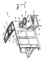
- figure 1 an exemplary embodiment of an installation 10 for the production of containers 12, in particular, but not exclusively, bottles as partially illustrated on the figure 6 .
- the installation 10 comprises at least a first protective enclosure 14 which delimits a first zone Z1 inside which is arranged at least one blowing unit 16 of containers 12.
- the blowing unit 16 is able to manufacture containers 12 by blow molding or by stretch-blow molding from preforms (not shown) which are previously thermally conditioned in an oven (not shown), in particular by heating by means of infrared radiation lamps.
- such a blowing unit 16 comprises in fact upstream a heating furnace for the thermal conditioning of the preforms, as well as transfer means (not shown) arranged at the outlet which are able to bring each of said heated preforms into a molds (not shown) that comprises at its periphery a carousel (not shown) in order to proceed to its transformation into a container 12 by blowing or by stretch-blow molding according to the applications.
- the installation 10 comprises a second containment chamber 18 which, at least partly contiguous to the first enclosure 14 adjacent by a common part 22, delimits a second sterile zone Z2 (see FIG. figure 2 ), inside which is arranged at least one filling unit 20 of the containers 12 manufactured by the blowing unit 16.
- Each of the enclosures 14 and 18 consists of a set of vertical walls which, in particular assembled together to form a parallelepiped generally, are respectively closed above and below, for example by a ceiling wall and the floor respectively.
- At least one of the vertical walls of the enclosures 14 and 18 includes doors to allow their crossing, in particular by an operator, and access to the interior of the installation 10.
- the first enclosure 14 comprises for example at least two access doors 15 forming part of its front vertical wall and which are more particularly visible on the figures 1 and 3 .
- the installation 10 comprises at least one opening 24 which is made in said common part 22 of the first and second enclosures 14 and 18.
- the opening 24 is intended to allow the transfer of the containers 12 of the blowing unit 16 to the filling unit 20.
- the installation 10 comprises closure means 26 of said opening 24 which are able to be selectively moved between at least one open position and one closed position.
- the open position corresponds to the position in which the closure means 26 allow the transfer of the containers 12 through the common opening 24 when the installation 10 is in a mode of operation, called production.
- the closed position corresponds to the position in which the closure means 26 prohibit any transfer by isolating the second enclosure 18.
- the closed position is in particular intended to allow at least in the second chamber 18 to carry out decontamination operations of the filling unit 20, when the installation 10 is in another mode of operation, called decontamination.
- the installation 10 comprises at least one actuator intended to control the displacement of the closure means 26 of the common opening 24 which slide between the open position corresponding to the production mode and the closed position corresponding to the decontamination mode.
- the closure means 26 provide in said closed position a hermetic closure of the opening 24 adapted to isolate the second chamber 18 comprising the filling unit 20 of the first chamber 14 comprising the blowing unit 16 of the containers 12 .
- closure means of the opening 24 are constituted by a flap 26 which is slidably mounted between said open and closed positions by means of two slides 27, respectively an upper slide and a lower slide.
- the slides 27 of the flap 26 are integral with the common part 22 and are respectively arranged above and below the opening 24 which here has a generally rectangular shape.
- the decontamination operations are preferably carried out chemically by spraying decontaminating solutions, such as sodium hydroxide (NaOH) or hydrogen peroxide (H 2 O 2 ), inside the second enclosure 18 .
- decontaminating solutions such as sodium hydroxide (NaOH) or hydrogen peroxide (H 2 O 2 )
- the installation 10 comprises a transfer device 28 for transferring the containers 12 between the blowing unit 16 and the filling unit 20.
- the transfer device 28 comprises at least one transfer wheel 30 which is adjacent to the opening 24 arranged in the common part 22 and which is intended to transfer, in production mode, the containers 12 through said opening 24.
- the transfer device 28 comprises, in addition to the transfer wheel 30, two other transfer wheels 32 and 34, respectively arranged upstream and downstream of the wheel 30 as illustrated in FIG. figure 2 .
- the wheels 30, 32 and 34 of the transfer device 28 are arranged relative to each other so as to each have an arcuate portion tangent to the portion of the adjacent wheel to determine an area in which the transfer containers 12 from one to the other.
- the first transfer wheel 32 is arranged between the inlet of the transfer wheel 30 and an exit zone of the carousel of the blowing unit 16 in which the molds are controlled in opening to allow the extraction of the containers manufactured by means of blowing means or stretch blow molding associated.
- the first transfer wheel 32 is intended to ensure the extraction of the containers 12 produced outside the molds and their transfer downstream, for example by means of transfer arms 36 provided at their free end with gripping means 38, such as tongs.
- the second transfer wheel 34 is arranged, downstream, between the output of the transfer wheel 30 and another carousel that comprises the filling unit 20, the filling stations of the containers 12 being distributed circumferentially in a regular manner around said carousel .
- the purpose of the present invention is to provide, for such an installation 10, a solution that is particularly able to eliminate the risk of contamination associated with the intervention of the operator.
- the invention proposes to modify the installation in order to eliminate any physical presence of the operator inside the installation, ie here in the transfer zone of the first zone Z1 of the first enclosure 14, and in doing so, eliminate the associated risks of contamination.
- the displacement of the movable part of the transfer wheel 30, respectively between said transfer and retracted position is able to be controlled from outside the installation 10, more precisely here since the outside of the first enclosure 14 inside which the transfer wheel 30 is arranged.
- the retraction of the part of the wheel 30 is therefore obtained without an operator having to open the doors 15 to cross the first chamber 14 and to physically enter the transfer zone ZT to intervene on the transfer wheel 30 so that the aforementioned risks of contamination are advantageously completely eliminated.
- control of the displacement of the transfer wheel 30 towards its retracted position in order to release the opening 24 is performed manually by an operator from outside the installation 10.
- the intervention of the operator is therefore required to at least perform the retraction operations of at least the portion of the transfer wheel 30 mounted mobile and then the decontamination of the filling unit 20 performed, the reverse operations to return said portion to its initial transfer position for the operation of the plant 10 in production mode.
- the transfer wheel 30 comprises a flange 40 respectively comprising an upper member 42 and a lower flange member 44 which are respectively integral with an upper portion 30A and a lower portion 30B of the wheel.
- the flange elements 42, 44 are at least interconnected by hinge means 46, as illustrated in particular on the figure 7 .
- the articulation means 46 are in particular able to allow the displacement of the upper part 30A of the wheel which, in the transfer position, is the only part of the transfer wheel 30 to extend through the opening 24.
- said upper portion 30A forms through the flange 40 a movable portion relative to the lower wheel portion 30B which constitutes when here a fixed portion.
- the upper part 30A of the transfer wheel 30 thus constitutes said at least one wheel portion which is mounted movably between the transfer position and the retracted position.
- the hinge means 46 are constituted by a pivot 48 defining a pivot axis A around which the upper flange member 42 pivots with respect to the lower flange member 44 in a gyration movement corresponding to the stroke the movable upper part 30A of the wheel between said transfer positions and retracted.
- the pivot axis A formed by the pivot 48 extends vertically and coaxially with the main axis of rotation of the wheel 30.
- the axes of the upper and lower parts 30A and 30B are, in the transfer position, coincident and determine globally the main axis of rotation of the wheel 30 which is no longer the case in the retracted position in which the upper portion 30A is off-axis relative to the lower fixed portion 30B.
- the transfer wheel 30 comprises locking means 50 able to immobilize, respectively in the transfer position or the retracted position, the upper part 30A with respect to the lower part 30B of the wheel.
- the locking means 50 of the wheel 30 are constituted by at least one pin 52 intended to be selectively introduced into at least a first housing 54 which, comprising two parts, extends vertically through the upper and lower elements 42 and 44 of the flange 40.
- the pin 52 When the pin 52 is inserted vertically into the first housing 54, the pin 52 then immobilizes the upper 30A and lower 30B parts of the transfer wheel 30 in a determined position corresponding to said transfer position of the wheel 30.
- the locking means 50 of the wheel 30 formed by the pin 52 are further adapted to be selectively introduced into at least a second housing 56 in which the pin 52 immobilizes the upper 30A and lower 30B parts of the wheel 30 in a determined position corresponding to said retracted position of the wheel 30.
- the second housing 56 is also made in two parts which extend vertically through the upper members 42 and lower 44 of the flange 40.
- the flange 40 comprises respectively the first housing 54 and the second housing 56 which are made, for example by drilling, through the upper members 42 and lower 44 of the flange 40.
- the locking means 50 formed by the pin 52 comprise a lower locking end intended to be introduced into the first housing 54 or the second housing 56 and another upper end which is connected to an operating member 58.
- the actuating member 58 of the locking pin 52 comprises, for example, a handle 60 which is mounted articulated along an axis of rotation B which is orthogonal to the main axis of the pin 52 of vertical orientation when it is in position locking in one of the housing 54 or 56.
- the handle 60 forming the operating member 58 comprises, for its articulated connection with the pin 52, two wings 62 which extend on either side of the upper end of the pin 52 and which each comprise a lower edge 64.
- each flange 62 has a profile which is intended to cooperate with a portion facing the horizontal upper face 66 of the upper member 42 of the flange 40.
- the handle 60 also leads to facilitating, for the operator intervening from outside the installation 10, the operations of the locking pin 52 between the first and second housing 54 and 56.
- the installation 10 comprises stop means 68 which, cooperating with a portion of the upper flange member 42, determine the position of the movable upper part 30A when the wheel 30 occupies said retracted position.
- the stop means 68 are adjustable via a screw / nut system in order to precisely adjust the position.
- the abutment means 68 also ensure proper vertical alignment of the two parts of the bore forming the second housing 56 so that the means 68 also facilitate the introduction of the locking pin 52 in the second housing 56 corresponding to the locking of the retracted position of the transfer wheel 30 as illustrated by the figure 9 .
- the transfer wheel 30 comprises locking means 70 which are intended to selectively block the rotation of the lower portion 44 of the wheel 30 relative to the means 72 for driving the rotation of the transfer wheel 30 when the installation is in production mode.
- the drive means 72 of the transfer wheel 30 consist, for example, of the means for rotating at least the wheel of the filling unit 20 so as to ensure a synchronous drive and, for this purpose, comprise minus one motor and motion transmission means such as belts.
- the drive means 72 are arranged in the lower part of the installation 10, the transfer wheel 30 comprising a rotary drive shaft which, forming essentially the lower part 30B, is connected by a belt. (not shown) to a drive wheel 74 that comprises the filling unit 20 (see figure 4 ).
- the means 70 for locking in rotation are for example constituted by at least one finger 76 which is received in a complementary notch 78 that includes the lower flange member 44 secured to the lower portion 30B of the wheel.
- the locking means 70 are movably mounted between at least one active position in which the finger 76 enters the notch 78 to ensure the locking in rotation and a passive position in which the finger 76 recesses, out of the notch 78.
- the finger 76 is movably mounted in a rectilinear motion of advance or recoil between said active and passive positions.
- the sliding of the finger 76 is controlled via a handle 80 connected to the finger 76 by connecting means 82 adapted to ensure the transmission of forces applied to the handle 80 to move the finger 76 between said positions.
- the handle 80 is rotatably mounted between a low position ( figure 7 ) corresponding to the passive position of the locking means 70 and a high position corresponding to the active position.
- the actuation of the handle 80 between said high and low positions thus causes, thanks to the connecting means 82, the movement of the finger 76 in or out of the notch 78 so that the locking by insertion of the finger 76 into the notch 78 is obtained by raising the handle from its low position to its upper position and, conversely, the unlocking by lowering the handle 80 from its upper position to its lower position.
- the blocking means 70 make it possible to cancel the residual torque caused by the drive means 72 which, however, remain able to drive the wheel of the filling unit 20 at low speed during operation in the decontamination mode.
- the first enclosure 14 for protecting the installation 10 comprises handling means 84 capable of allowing remote manipulations by an operator and without direct contact of the operator with the manipulated organs from which the operator who intervenes since the outside of the first enclosure 14, is isolated by said manipulation means 84.
- the handling means 84 are constituted by at least one glove 88 extended by a sleeve 90, illustrated in detail in FIG. figure 5 .
- one of the doors 15 of the first chamber 14 has an opening 86 on which is mounted in a sealed manner the end of the sleeve 90 located opposite to that where the glove 88 handling.
- the handling means 84 are therefore advantageously integrated in a front wall portion of the enclosure 14 close to the transfer wheel 30 so as to allow an operator to proceed manually from the outside of the first enclosure 14 of protection, the manipulations required to move the transfer wheel 30 between the transfer position and the retracted position.
- the operator intervenes remotely from the outside without ever penetrating inside the first zone Z1 in which are located the transfer wheel 30 and the blowing unit 16 of the containers 12, in particular not in the zone ZT transfer of said first zone Z1 in which is arranged the transfer wheel 30 and is directly adjacent to the opening 24.
- only part of at least one of its arms crosses the first enclosure 14 via the glove 88-90 forming the means of manipulation 84 and thanks to which the operator intervenes remotely without ever being able to constitute a vector of introduction of pathogens.
- the totally isolated operator does not is thus more likely to be a vector capable of introducing pathogens into the plant 10 and especially to directly or indirectly introduce pathogens into the second sterile zone Z2 of the plant. filling unit 20.
- the locking means 50 or the locking means 70 are easily maneuvered manually by the operator via the glove 88-90 forming the remote manipulation means 84, and this through the first enclosure 14 without any risk of contamination.
- the disassembly operations of the means 92 for holding the containers 12 during the transfer by the transfer wheel 30 that were previously necessary are eliminated, said means 92 being - in the example shown in the figures - constituted by the three superposed trays each circumferentially provided with notches intended to cooperate in known manner with a part of the container 12.
- such holding means 92 are associated with first guiding means 94 which, when they extend through the opening 24 in production mode, are also mounted movable between two positions, one working, another retracted.
- the retraction of the first guiding means 94 of the containers during the transfer of the wheel 30 to the wheel 34 is automatically controlled by means of at least one actuator, such as a jack.
- the installation 10 also comprises second guide means 94 which are arranged between the first transfer wheel 32 and the transfer wheel 30, said second guide means 94 are also movably mounted between a working position and a retracted position.
- the second guide means 94 are retracted automatically via at least one actuator so as not to interfere with the retraction of the transfer wheel 30.
- the operations to be performed by the operator to close the opening 24 by the flap 26 are therefore particularly simplified since they consist mainly in pivoting the movable upper portion 30A of the transfer wheel 30 and then to replace the locking means 50 or to actuate the locking means 70.
- the invention also makes it possible in an installation 10 equipped with such a transfer wheel 30 to quickly close the opening 24 intended to hermetically isolate the filling unit. 20 and therefore to a reduced intervention time before the implementation of the decontamination mode.
- the installation 10 is able to operate in production mode in which the blowing unit 16 converts preforms previously thermally conditioned by blowing or stretch blow molding into as many containers 12 which are successively transferred by the wheels 30, 32 and 34 of the transfer device 28 to the filling unit 20 where the containers 12 are filled and preferably clogged.
- the transfer wheel 30 occupies its transfer position in which the means 92 holding the containers 12 that comprises the upper portion 30A of the wheel 30 extend horizontally through the opening 24 here included in a vertical plane transverse orientation.
- the shutter means 26 formed by the shutter occupy their open position so that the transfer of the containers 12 by the means 92 of the transfer wheel 30 can be implemented.
- the installation 10 is then stopped so that the production of the containers 12 ceases.
- the operator then intervenes to perform the various operations prior to the implementation of the decontamination mode.
- the operator must indeed proceed to the retraction of at least the portion 30A of the transfer wheel 30 and the closure of the opening 24 by the flap 26, all of these operations or maneuvers being all carried out since the outside of the first enclosure 14 without the operator having to cross said enclosure 14.
- the operator first proceeds to disengage the rotational drive of the transfer wheel 30 by the means 72 so that the wheel is free to turn on itself, the disengagement is for example obtained from outside from a control panel via means automatically controlling a pneumatic clutch.
- the operator passes at least one of his hands through the opening 86 of the door 15 of the first chamber 14 to introduce it into the remote manipulation means 84 formed here by at least one glove 88 that extends the sleeve 90 sealingly connected to the opening 86.
- the operator then stands upright on the outside of the installation 10, more precisely in front of the door 15 having the opening 86, and the operator is able to manually actuate the handle 80 of the locking means 70 by said handle 80 to its upper position to simultaneously cause the movement of the finger 76 from its passive position to its active position in which the finger 76 is introduced into the notch 78 of the lower member 44 of the flange 40.
- the pin 52 is then immediately introduced into the upper part of the second housing 56 that comprises the upper member 42 of the flange 40.
- attachment means such as a chain, are provided for attaching the locking means 50 to a portion of the wheel 30 or flange 40 so that they can not be lost or fall during handling. and that the operator is always able to seize it with the glove 88.
- the upper element 42 and the lower element 44 of the flange are then no longer locked together and are connected only by the pivot 48 which forms the articulation means 46.
- the operator is then able to move the upper part 30A forming said movable part of the wheel to make it perform, in a gyration movement about the vertical pivot axis A, the displacement from the transfer position illustrated in FIGS. figures 6 and 7 to the retracted position illustrated in figures 8 and 9 .
- the operator is particularly informed that the upper part 30A of the transfer wheel 30 has reached said retracted position when, the upper element 42 of the flange 40 coming into contact with the abutment means 68 provided for this purpose, an effort of resistance is opposed to it.
- the movable upper part 30A of the transfer wheel 30 occupying said retracted position the operator can proceed to lock the flange 40 of the wheel 30 by introducing the pin 52 of the locking means 50 into the second housing 56 as illustrated to the figure 9 .
- the abutment means 68 are adjustable so as to allow for each installation 10 and transfer wheel 30 a precise adjustment which, ensuring the correct positioning in the retracted position, ensures a perfect vertical alignment of the two holes which, respectively made in the elements upper 42 and lower 44, together form the second housing 56.
- the pin 52 is in the locking position in the second housing 56 and in the upper element 42 and in the lower element 44 respectively, the two parts which, forming the first housing 54, are angularly offset relative to each other; to the other.
- the operator also removes the first and second means 94 for guiding the containers 12 associated with the holding means 92, the retraction being advantageously obtained automatically by means of actuators which are controlled from outside the installation. 10 by the operator.
- the operator controls for example from a desk, the automatic closure of the flap 26 which is advantageously moved transversely forward by actuators from its open position to its closed position of the opening 24.
- the installation 10 comprises around the opening 24 sealing means 96 to complete the closure of the opening 24 and ensure a tight seal.
- the sealing means 96 are interposed between the edges of the opening 24 arranged in the wall 22 and around the flap 26.
- the sealing means 96 consist of one or more seals capable of being inflated to ensure a hermetic closure of the opening 24.
- the operator proceeds in reverse order to the same manipulations and commands that have just been described in order to reposition all the organs in the initial position that they previously occupied and which corresponds to the operation in production mode of the installation 10.
- the installation 10 comprises at least one actuator capable of being controlled remotely to automatically proceed at least to the displacement of the upper part 30A forming the part of the transfer wheel 30 which is mounted movably between the transfer position and the retracted position respectively.
- the locking means 50 are for example advantageously integrated with an actuator controlling the pivoting of the upper and lower flange members 42, which actuator is selectively controlled to obtain the retraction of the movable upper part 30A of the transfer wheel 30.
- Such selective control of the actuator or actuators is either fully automated or controlled by an operator via man / machine interface means such as a control panel disposed outside the installation 10.
- the handle 80 for controlling the rotation locking means 70 is for example capable of being replaced by an actuator able to selectively control the movement of the finger 76 with respect to the notch 78.
- the invention is capable of being implemented in an existing installation 10 by making the necessary modifications of the transfer wheel 30, in particular with a view to introducing the flange 40 thanks to which the upper part 30A is retractable since the outside of the installation 10.
Landscapes
- Engineering & Computer Science (AREA)
- Mechanical Engineering (AREA)
- Manufacturing & Machinery (AREA)
- Filling Of Jars Or Cans And Processes For Cleaning And Sealing Jars (AREA)
- Apparatus For Disinfection Or Sterilisation (AREA)
- Supplying Of Containers To The Packaging Station (AREA)
- Specific Conveyance Elements (AREA)
Claims (9)
- Anlage (10) zur Produktion von Behältern (12), insbesondere von Flaschen, die mindestens aufweist:- eine erste Schutzkammer (14), die eine erste Zone (Z1) begrenzt, innerhalb der mindestens eine Einheit (16) zum Blasen von Behältern angeordnet ist,- eine zweite Einschließungskammer (18), die, zumindest zum Teil durch einen gemeinsamen Teil (22) an die angrenzende erste Kammer (14) angefügt, eine sterile zweite Zone (Z2) begrenzt, innerhalb der mindestens eine Fülleinheit (20) der hergestellten Behälter (12) angeordnet ist,- mindestens eine Öffnung (24), die, hergestellt im gemeinsamen Teil (22) der ersten und zweiten Kammern (14, 18), dazu bestimmt ist, die Übertragung der Behälter (12) von der Blaseinheit (16) zur Fülleinheit (20) zu erlauben,- Verschlusseinrichtungen (26) der Öffnung (24), die selektiv zwischen einer offenen Stellung, in der die Verschlusseinrichtungen (26) die Übertragung des Behälter (12) durch die gemeinsame Öffnung (24) erlauben, und einer geschlossenen Stellung verschoben werden können, in der die Verschlusseinrichtungen jede Übertragung verhindern, indem sie die zweite Kammer isolieren, um eine Dekontamination der Fülleinheit durchzuführen, und- mindestens eine Übertragungsvorrichtung (28), die mindestens ein Übertragungsrad (30) aufweist, das, der Öffnung (24) benachbart, die Behälter (12) zwischen der Blaseinheit (16) und der Fülleinheit (20) übertragen kann,dadurch gekennzeichnet, dass mindestens ein Teil (30A) des Übertragungsrads (30) beweglich montiert ist zwischen mindestens:- einer ersten Übertragungsstellung, in der der mindestens eine Teil (30A) des Rads sich durch die Öffnung (24) erstreckt, um in einem sogenannten Produktionsmodus die Übertragung der Behälter (12) beim Betrieb der Anlage (10) zu gewährleisten, und- einer zweiten eingezogenen Stellung, in der der mindestens eine Teil (30A) des Rads verschoben ist, um das Schließen der Öffnung (24) durch die zugeordneten Verschlusseinrichtungen (26) für den Betrieb der Anlage in einem sogenannten Dekontaminationsmodus zu erlauben,dass die Verschiebung des beweglichen Teils (30A) des Übertragungsrads (30) zwischen der Übertragungs
und der eingezogenen Stellung von außerhalb der Anlage (10) gesteuert wird, und dass das Übertragungsrad (30) einen Flansch (40) aufweist, der mindestens ein oberes (42) und ein unteres Flanschelement (44) aufweist, die mit einem oberen Teil (30A) bzw. einem unteren Teil (30B) des Rads (30) fest verbunden sind, wobei die Flanschelemente (42, 44) mindestens durch Anlenkeinrichtungen (46) verbunden sind, die die Verschiebung zwischen der Übertragungsstellung und der eingezogenen Stellung des den beweglichen Teil formenden oberen Teils (30A) des Rads (30) bezüglich des einen ortsfesten Teil formenden unteren Teils (30B) des Rads (30) ermöglichen können. - Anlage (10) nach Anspruch 1, dadurch gekennzeichnet, dass die Anlenkeinrichtungen (46) aus einem Drehzapfen (48) bestehen, der eine Schwenkachse (A) bestimmt, um die das obere Flanschelement (42) bezüglich des unteren Flanschelements (44) gemäß einer Rotationsbewegung entsprechend dem Hub des oberen beweglichen Teils (30A) des Rads (30) zwischen der Übertragungsstellung und der eingezogenen Stellung schwenkt.
- Anlage (10) nach einem der Ansprüche 1 oder 2, dadurch gekennzeichnet, dass das Übertragungsrad (30) Verriegelungseinrichtungen (50) aufweist, die den oberen Teil (30A) bezüglich des unteren Teils (30B) des Rads in der Übertragungsstellung bzw. der eingezogenen Stellung arretieren können.
- Anlage (10) nach Anspruch 3, dadurch gekennzeichnet, dass die Verriegelungseinrichtungen (50) des Rads aus mindestens einem Stift (52) bestehen, der dazu bestimmt ist, selektiv in eine erste Aufnahme (54), die sich durch das obere (42) und das untere Element (44) des Flanschs (40) erstreckt, wobei der Stift (52) den oberen (30A) und den unteren Teil (30B) des Rads in einer bestimmten Stellung arretiert, die der Übertragungsstellung entspricht, bzw. in eine zweite Aufnahme (56) eingeführt zu werden, die sich durch das obere (42) und das untere Element (44) des Flanschs (40) erstreckt, wobei der Stift (52) den oberen (30A) und den unteren Teil (30B) des Rads in einer anderen bestimmten Stellung arretiert, die der eingezogenen Stellung des Übertragungsrads (30) entspricht.
- Anlage (10) nach Anspruch 4, dadurch gekennzeichnet, dass die Anlage (10) Anschlageinrichtungen (68) aufweist, die, fähig, mit einem Teil des oberen Flanschelements (42) zusammenzuwirken, die Stellung des beweglichen oberen Teils (30A) des Rads (30) in der eingezogenen Stellung bestimmen, insbesondere, um die Einführung des Verriegelungsstifts (52) in die zweite Aufnahme (56) zu vereinfachen.
- Anlage (10) nach Anspruch 1, dadurch gekennzeichnet, dass das Übertragungsrad (30) Blockiereinrichtungen (70) aufweist, die dazu bestimmt sind, selektiv die Drehblockierung des ortsfesten unteren Teils (30B) des Rads (30) bezüglich der Drehantriebseinrichtungen (72) des Übertragungsrads (30) zu gewährleisten, wenn die Anlage (10) im Dekontaminationsmodus ist.
- Anlage (10) nach Anspruch 6, dadurch gekennzeichnet, dass die Drehblockiereinrichtungen (70) aus mindestens einem Finger (76) bestehen, der in einer komplementären Aussparung (78) aufgenommen wird, die das untere Flanschelement (44) aufweist, das fest mit dem unteren Teil (30B) des Rads verbunden ist.
- Anlage (10) nach einem der vorhergehenden Ansprüche, dadurch gekennzeichnet, dass der erste Schutzraum (14) Handhabungseinrichtungen (84), wie mindestens einen Handschuh (88, 90) aufweist, der dicht mit einer im ersten Raum (14) ausgeführten Öffnung (86) verbunden ist, um manuell zumindest die Verschiebung des Übertragungsrads (30) zwischen der Übertragungsstellung und der eingezogenen Stellung von außerhalb der ersten Kammer (14) der Anlage (10) zu steuern.
- Anlage (10) nach einem der vorhergehenden Ansprüche, dadurch gekennzeichnet, dass die Anlage (10) mindestens ein Stellglied aufweist, um mindestens die Verschiebung des Übertragungsrads (30) zwischen der Übertragungsstellung und der eingezogenen Stellung von außerhalb der ersten Kammer (14) der Anlage (10) automatisch zu steuern.
Applications Claiming Priority (2)
| Application Number | Priority Date | Filing Date | Title |
|---|---|---|---|
| FR0950154A FR2940964B1 (fr) | 2009-01-13 | 2009-01-13 | Installation pour la production de recipients comportant une roue de transfert escamotable |
| PCT/EP2010/050105 WO2010081759A1 (fr) | 2009-01-13 | 2010-01-07 | Installation pour la production de récipients comportant une roue de transfert escamotable |
Publications (3)
| Publication Number | Publication Date |
|---|---|
| EP2376366A1 EP2376366A1 (de) | 2011-10-19 |
| EP2376366B1 EP2376366B1 (de) | 2014-07-30 |
| EP2376366B2 true EP2376366B2 (de) | 2018-08-15 |
Family
ID=41010856
Family Applications (1)
| Application Number | Title | Priority Date | Filing Date |
|---|---|---|---|
| EP10700969.8A Active EP2376366B2 (de) | 2009-01-13 | 2010-01-07 | Anlage zur herstellung von behältern mit einziehbarem transferrad |
Country Status (7)
| Country | Link |
|---|---|
| US (1) | US8647101B2 (de) |
| EP (1) | EP2376366B2 (de) |
| JP (1) | JP5378543B2 (de) |
| CN (1) | CN102282092B (de) |
| DE (1) | DE202010018582U1 (de) |
| FR (1) | FR2940964B1 (de) |
| WO (1) | WO2010081759A1 (de) |
Families Citing this family (23)
| Publication number | Priority date | Publication date | Assignee | Title |
|---|---|---|---|---|
| DE102010000501B4 (de) * | 2010-02-22 | 2021-05-27 | Krones Aktiengesellschaft | Behälterformungs- und Behälterbehandlungsanlage |
| CN102145871B (zh) * | 2011-03-21 | 2012-08-29 | 楚天科技股份有限公司 | 轧盖机 |
| DE102012003353B4 (de) * | 2012-02-21 | 2013-10-24 | Khs Gmbh | Anschlusselement für einen Maschinenschutz, Maschinenschutz mit einem solchen Anschlusselement sowie Behälterbehandlungsmaschine |
| FR2990135B1 (fr) | 2012-05-04 | 2016-05-06 | Sidel Participations | Ensemble pour la decontamination d'un moule de fabrication de recipient et procede de decontamination |
| CN102756915A (zh) * | 2012-06-21 | 2012-10-31 | 常州金海棠茶果专业合作社 | 压盖机的拨瓶装置 |
| EP2759495A1 (de) * | 2013-01-28 | 2014-07-30 | Sidel S.p.a. Con Socio Unico | System und Verfahren für den Betrieb einer Maschine zur Verarbeitung von Behältern mit zusammenwirkenden Drehteilen |
| DE102014103900A1 (de) * | 2014-03-21 | 2015-09-24 | Krones Ag | Transporteinrichtung und Transportverfahren für Behälterbehandlungsanlage |
| FR3020007B1 (fr) * | 2014-04-17 | 2016-05-20 | Sidel Participations | Installation pour la production de recipients comportant un dispositif de desinfection d'une roue de transfert |
| JP2018538184A (ja) | 2015-12-22 | 2018-12-27 | シデル パルティシパションSidel Participations | 容器成形装置の延伸手段を滅菌する方法および容器製造設備 |
| KR102360301B1 (ko) * | 2016-09-14 | 2022-02-10 | 시부야 코교 가부시키가이샤 | 충전 시스템 |
| FR3057198B1 (fr) * | 2016-10-12 | 2018-10-05 | Sidel Participations | Installation de fabrication de recipients comportant une roue de contournement d'une station de revetement |
| FR3069307B1 (fr) * | 2017-07-21 | 2019-07-26 | Sidel Participations | Installation de manutention d'articles a maintenance securisee |
| IT201700094800A1 (it) * | 2017-08-21 | 2019-02-21 | Lameplast Spa | Impianto per la produzione di contenitori, particolarmente contenitori per prodotti medicali, farmaceutici, cosmetici, alimentari o simili |
| DE202017105447U1 (de) | 2017-09-08 | 2018-12-18 | Krones Aktiengesellschaft | Behälterbehandlungsanlage |
| DE102017215860A1 (de) | 2017-09-08 | 2019-03-14 | Krones Aktiengesellschaft | Behälterbehandlungsanlage und Verfahren zum Herstellen zweier getrennter Bereiche in einer solchen Anlage |
| IT201900020628A1 (it) * | 2019-11-08 | 2021-05-08 | Sidel Participations Sas | Macchina di trattamento per recipienti e metodo di azionamento di una macchina di trattamento |
| IT201900022677A1 (it) | 2019-12-02 | 2021-06-02 | Gea Procomac Spa | Sistema di trasferimento di contenitori o preforme e apparato di trattamento o lavorazione comprendente tale sistema |
| US12103788B2 (en) * | 2020-04-03 | 2024-10-01 | Ferrum Packaging Ag | Apparatus for processing containers |
| JP7659180B2 (ja) * | 2021-05-31 | 2025-04-09 | 澁谷工業株式会社 | 処理システム |
| DE102021117469A1 (de) * | 2021-07-06 | 2023-01-12 | Krones Aktiengesellschaft | Vorrichtung zum Zuführen eines Behälterverschlusses und Verschließvorrichtung |
| DE102022122085A1 (de) * | 2022-08-31 | 2024-02-29 | Krones Aktiengesellschaft | Vorrichtung und Verfahren zum Umformen von Kunststoffvorformlingen zu Kunststoffbehältnissen mit Reinraum mit abnehmbarer Deckeleinrichtung |
| FR3149004B1 (fr) | 2023-05-24 | 2025-04-18 | Sidel Participations | Procede de commande de l’ouverture d’un volet d’une enceinte en surpression |
| DE102024106891A1 (de) | 2024-03-11 | 2025-09-11 | Krones Aktiengesellschaft | Vorrichtung und Verfahren zum Umformen von Kunststoffvorformlingen zu Kunststoffbehältnissen mit Reinraum und Partikelentfernungseinrichtung |
Citations (5)
| Publication number | Priority date | Publication date | Assignee | Title |
|---|---|---|---|---|
| US3035886A (en) † | 1957-10-07 | 1962-05-22 | Fmc Corp | Method of sterilizing |
| JP2003237936A (ja) † | 2002-02-15 | 2003-08-27 | Mitsubishi Heavy Ind Ltd | クリーンチャンバー開口部の遮断装置 |
| DE102005012507A1 (de) † | 2005-03-16 | 2006-09-21 | Krones Ag | Verfahren und Vorrichtung betrefffend das Sterilabfüllen von Flüssigkeiten |
| DE102006035109A1 (de) † | 2006-07-29 | 2008-01-31 | Krones Ag | Fördereinrichtung |
| DE102006053193A1 (de) † | 2006-11-09 | 2008-05-15 | Krones Ag | Vorrichtung und Verfahren zur Herstellung von Kunststoffbehältern |
Family Cites Families (11)
| Publication number | Priority date | Publication date | Assignee | Title |
|---|---|---|---|---|
| US4927205A (en) * | 1987-07-02 | 1990-05-22 | Feco Engineered Systems, Inc. | Rotational container holding device and method |
| JPH08164925A (ja) * | 1994-12-12 | 1996-06-25 | Coca Cola Co:The | 飲料包装装置 |
| EP0726216B1 (de) * | 1995-02-07 | 1998-09-09 | Hermann Kronseder | Transportstern für Gefässe |
| US6298638B1 (en) * | 1997-04-21 | 2001-10-09 | Graham Packaging Company, L.P. | System for blow-molding, filling and capping containers |
| FR2766169B1 (fr) * | 1997-07-17 | 1999-10-01 | Sidel Sa | Installation de sterilisation au defile de preformes de recipients en matiere thermoplastique |
| DE19928325A1 (de) * | 1999-06-21 | 2000-12-28 | Krones Ag | Abfüllvorrichtung für Flaschen |
| JP2003146427A (ja) | 2001-11-14 | 2003-05-21 | Shibuya Kogyo Co Ltd | 容器搬送装置 |
| FR2887525B1 (fr) | 2005-06-24 | 2007-09-07 | Sidel Sas | Installation produisant des bouteilles steriles par soufflage a partir de preformes sterilisees |
| FR2907684B1 (fr) | 2006-10-26 | 2009-12-04 | Sidel Participations | Procede de sterilisation d'une preforme, installation et four pour la fabrication de recipients steriles selon ce procede. |
| FR2915127B1 (fr) | 2007-04-20 | 2012-10-12 | Sidel Participations | Installation pour la fabrication de recipients comportant une enceinte de protection equipee d'un systeme d'insufflation d'air filtre |
| CN101274732B (zh) * | 2008-05-19 | 2010-06-02 | 长沙楚天科技有限公司 | 大输液灌装加塞机 |
-
2009
- 2009-01-13 FR FR0950154A patent/FR2940964B1/fr not_active Expired - Fee Related
-
2010
- 2010-01-07 JP JP2011545714A patent/JP5378543B2/ja active Active
- 2010-01-07 CN CN2010800043863A patent/CN102282092B/zh active Active
- 2010-01-07 WO PCT/EP2010/050105 patent/WO2010081759A1/fr not_active Ceased
- 2010-01-07 DE DE202010018582.3U patent/DE202010018582U1/de not_active Expired - Lifetime
- 2010-01-07 US US13/139,371 patent/US8647101B2/en not_active Expired - Fee Related
- 2010-01-07 EP EP10700969.8A patent/EP2376366B2/de active Active
Patent Citations (5)
| Publication number | Priority date | Publication date | Assignee | Title |
|---|---|---|---|---|
| US3035886A (en) † | 1957-10-07 | 1962-05-22 | Fmc Corp | Method of sterilizing |
| JP2003237936A (ja) † | 2002-02-15 | 2003-08-27 | Mitsubishi Heavy Ind Ltd | クリーンチャンバー開口部の遮断装置 |
| DE102005012507A1 (de) † | 2005-03-16 | 2006-09-21 | Krones Ag | Verfahren und Vorrichtung betrefffend das Sterilabfüllen von Flüssigkeiten |
| DE102006035109A1 (de) † | 2006-07-29 | 2008-01-31 | Krones Ag | Fördereinrichtung |
| DE102006053193A1 (de) † | 2006-11-09 | 2008-05-15 | Krones Ag | Vorrichtung und Verfahren zur Herstellung von Kunststoffbehältern |
Also Published As
| Publication number | Publication date |
|---|---|
| US8647101B2 (en) | 2014-02-11 |
| JP5378543B2 (ja) | 2013-12-25 |
| CN102282092A (zh) | 2011-12-14 |
| JP2012515122A (ja) | 2012-07-05 |
| FR2940964B1 (fr) | 2011-02-11 |
| FR2940964A1 (fr) | 2010-07-16 |
| EP2376366A1 (de) | 2011-10-19 |
| EP2376366B1 (de) | 2014-07-30 |
| US20110250307A1 (en) | 2011-10-13 |
| CN102282092B (zh) | 2013-07-03 |
| WO2010081759A1 (fr) | 2010-07-22 |
| DE202010018582U1 (de) | 2017-11-29 |
Similar Documents
| Publication | Publication Date | Title |
|---|---|---|
| EP2376366B2 (de) | Anlage zur herstellung von behältern mit einziehbarem transferrad | |
| US8950624B2 (en) | Externally operated alpha port system for use with a rapid transfer port | |
| EP3131733B1 (de) | Anlage zur herstellung von behältern, mit einer vorrichtung zur desinfektion eines transferrads | |
| CN104441579B (zh) | 用于使塑料型胚成形的具有洁净室的装置 | |
| CA2997677C (en) | Transfer device | |
| EP2852486A1 (de) | Behälter fertigungsanlage mit einem roboter in einer positionierung für den betrieb von mindestens zwei einheiten | |
| JP6054624B2 (ja) | 枢動およびロックの運動を連動させた、プラスチック予備成形物をプラスチック容器へと変換するための装置および方法 | |
| JP6961240B2 (ja) | 滅菌粒状バルク物質を搬送し、滅菌粒状バルク物質をアイソレーター内に移送する方法、並びに、コンテナ、アイソレーター及びアイソレーターとコンテナとの組合せ | |
| CN102320123A (zh) | 具有一消毒室的用于塑形塑料预塑形件的设备 | |
| EP1982820A1 (de) | Vorrichtung zum Herstellen von Behältern mit einem mit einem System zum Einblasen von gefilterter Luft versehenen Schutzgehäuse | |
| US8550799B2 (en) | Sterile de-molding apparatus and method | |
| JP5992199B2 (ja) | プラスチックプリフォームをプラスチック容器に成形する装置およびその方法 | |
| CN104284681B (zh) | 包括模具去污装置的由预型件制造容器的设备和去污方法 | |
| WO2024240451A1 (fr) | Procede de commande de l'ouverture d'un volet d'une enceinte en surpression | |
| JP4737970B2 (ja) | アイソレータおよび移送容器 | |
| CN108472397B (zh) | 容器模制装置的拉制部件的灭菌方法以及容器制造设备 |
Legal Events
| Date | Code | Title | Description |
|---|---|---|---|
| PUAI | Public reference made under article 153(3) epc to a published international application that has entered the european phase |
Free format text: ORIGINAL CODE: 0009012 |
|
| 17P | Request for examination filed |
Effective date: 20110707 |
|
| AK | Designated contracting states |
Kind code of ref document: A1 Designated state(s): AT BE BG CH CY CZ DE DK EE ES FI FR GB GR HR HU IE IS IT LI LT LU LV MC MK MT NL NO PL PT RO SE SI SK SM TR |
|
| DAX | Request for extension of the european patent (deleted) | ||
| REG | Reference to a national code |
Ref country code: DE Ref legal event code: R079 Ref document number: 602010017872 Country of ref document: DE Free format text: PREVIOUS MAIN CLASS: B67C0003220000 Ipc: B29C0049420000 |
|
| RIC1 | Information provided on ipc code assigned before grant |
Ipc: B67C 3/22 20060101ALI20140220BHEP Ipc: B29C 49/06 20060101ALI20140220BHEP Ipc: B29C 49/42 20060101AFI20140220BHEP Ipc: B67C 7/00 20060101ALI20140220BHEP Ipc: B65G 47/84 20060101ALI20140220BHEP |
|
| GRAP | Despatch of communication of intention to grant a patent |
Free format text: ORIGINAL CODE: EPIDOSNIGR1 |
|
| INTG | Intention to grant announced |
Effective date: 20140328 |
|
| GRAS | Grant fee paid |
Free format text: ORIGINAL CODE: EPIDOSNIGR3 |
|
| GRAA | (expected) grant |
Free format text: ORIGINAL CODE: 0009210 |
|
| AK | Designated contracting states |
Kind code of ref document: B1 Designated state(s): AT BE BG CH CY CZ DE DK EE ES FI FR GB GR HR HU IE IS IT LI LT LU LV MC MK MT NL NO PL PT RO SE SI SK SM TR |
|
| REG | Reference to a national code |
Ref country code: GB Ref legal event code: FG4D Free format text: NOT ENGLISH |
|
| REG | Reference to a national code |
Ref country code: CH Ref legal event code: EP |
|
| REG | Reference to a national code |
Ref country code: AT Ref legal event code: REF Ref document number: 679737 Country of ref document: AT Kind code of ref document: T Effective date: 20140815 |
|
| REG | Reference to a national code |
Ref country code: IE Ref legal event code: FG4D Free format text: LANGUAGE OF EP DOCUMENT: FRENCH |
|
| REG | Reference to a national code |
Ref country code: DE Ref legal event code: R096 Ref document number: 602010017872 Country of ref document: DE Effective date: 20140911 |
|
| REG | Reference to a national code |
Ref country code: AT Ref legal event code: MK05 Ref document number: 679737 Country of ref document: AT Kind code of ref document: T Effective date: 20140730 |
|
| REG | Reference to a national code |
Ref country code: NL Ref legal event code: VDEP Effective date: 20140730 |
|
| REG | Reference to a national code |
Ref country code: LT Ref legal event code: MG4D |
|
| PG25 | Lapsed in a contracting state [announced via postgrant information from national office to epo] |
Ref country code: NO Free format text: LAPSE BECAUSE OF FAILURE TO SUBMIT A TRANSLATION OF THE DESCRIPTION OR TO PAY THE FEE WITHIN THE PRESCRIBED TIME-LIMIT Effective date: 20141030 Ref country code: FI Free format text: LAPSE BECAUSE OF FAILURE TO SUBMIT A TRANSLATION OF THE DESCRIPTION OR TO PAY THE FEE WITHIN THE PRESCRIBED TIME-LIMIT Effective date: 20140730 Ref country code: BG Free format text: LAPSE BECAUSE OF FAILURE TO SUBMIT A TRANSLATION OF THE DESCRIPTION OR TO PAY THE FEE WITHIN THE PRESCRIBED TIME-LIMIT Effective date: 20141030 Ref country code: ES Free format text: LAPSE BECAUSE OF FAILURE TO SUBMIT A TRANSLATION OF THE DESCRIPTION OR TO PAY THE FEE WITHIN THE PRESCRIBED TIME-LIMIT Effective date: 20140730 Ref country code: SE Free format text: LAPSE BECAUSE OF FAILURE TO SUBMIT A TRANSLATION OF THE DESCRIPTION OR TO PAY THE FEE WITHIN THE PRESCRIBED TIME-LIMIT Effective date: 20140730 Ref country code: PT Free format text: LAPSE BECAUSE OF FAILURE TO SUBMIT A TRANSLATION OF THE DESCRIPTION OR TO PAY THE FEE WITHIN THE PRESCRIBED TIME-LIMIT Effective date: 20141202 Ref country code: GR Free format text: LAPSE BECAUSE OF FAILURE TO SUBMIT A TRANSLATION OF THE DESCRIPTION OR TO PAY THE FEE WITHIN THE PRESCRIBED TIME-LIMIT Effective date: 20141031 Ref country code: LT Free format text: LAPSE BECAUSE OF FAILURE TO SUBMIT A TRANSLATION OF THE DESCRIPTION OR TO PAY THE FEE WITHIN THE PRESCRIBED TIME-LIMIT Effective date: 20140730 |
|
| PG25 | Lapsed in a contracting state [announced via postgrant information from national office to epo] |
Ref country code: AT Free format text: LAPSE BECAUSE OF FAILURE TO SUBMIT A TRANSLATION OF THE DESCRIPTION OR TO PAY THE FEE WITHIN THE PRESCRIBED TIME-LIMIT Effective date: 20140730 Ref country code: CY Free format text: LAPSE BECAUSE OF FAILURE TO SUBMIT A TRANSLATION OF THE DESCRIPTION OR TO PAY THE FEE WITHIN THE PRESCRIBED TIME-LIMIT Effective date: 20140730 Ref country code: IS Free format text: LAPSE BECAUSE OF FAILURE TO SUBMIT A TRANSLATION OF THE DESCRIPTION OR TO PAY THE FEE WITHIN THE PRESCRIBED TIME-LIMIT Effective date: 20141130 Ref country code: LV Free format text: LAPSE BECAUSE OF FAILURE TO SUBMIT A TRANSLATION OF THE DESCRIPTION OR TO PAY THE FEE WITHIN THE PRESCRIBED TIME-LIMIT Effective date: 20140730 Ref country code: HR Free format text: LAPSE BECAUSE OF FAILURE TO SUBMIT A TRANSLATION OF THE DESCRIPTION OR TO PAY THE FEE WITHIN THE PRESCRIBED TIME-LIMIT Effective date: 20140730 Ref country code: NL Free format text: LAPSE BECAUSE OF FAILURE TO SUBMIT A TRANSLATION OF THE DESCRIPTION OR TO PAY THE FEE WITHIN THE PRESCRIBED TIME-LIMIT Effective date: 20140730 Ref country code: PL Free format text: LAPSE BECAUSE OF FAILURE TO SUBMIT A TRANSLATION OF THE DESCRIPTION OR TO PAY THE FEE WITHIN THE PRESCRIBED TIME-LIMIT Effective date: 20140730 |
|
| PG25 | Lapsed in a contracting state [announced via postgrant information from national office to epo] |
Ref country code: EE Free format text: LAPSE BECAUSE OF FAILURE TO SUBMIT A TRANSLATION OF THE DESCRIPTION OR TO PAY THE FEE WITHIN THE PRESCRIBED TIME-LIMIT Effective date: 20140730 Ref country code: SK Free format text: LAPSE BECAUSE OF FAILURE TO SUBMIT A TRANSLATION OF THE DESCRIPTION OR TO PAY THE FEE WITHIN THE PRESCRIBED TIME-LIMIT Effective date: 20140730 Ref country code: DK Free format text: LAPSE BECAUSE OF FAILURE TO SUBMIT A TRANSLATION OF THE DESCRIPTION OR TO PAY THE FEE WITHIN THE PRESCRIBED TIME-LIMIT Effective date: 20140730 Ref country code: CZ Free format text: LAPSE BECAUSE OF FAILURE TO SUBMIT A TRANSLATION OF THE DESCRIPTION OR TO PAY THE FEE WITHIN THE PRESCRIBED TIME-LIMIT Effective date: 20140730 Ref country code: RO Free format text: LAPSE BECAUSE OF FAILURE TO SUBMIT A TRANSLATION OF THE DESCRIPTION OR TO PAY THE FEE WITHIN THE PRESCRIBED TIME-LIMIT Effective date: 20140730 |
|
| REG | Reference to a national code |
Ref country code: DE Ref legal event code: R026 Ref document number: 602010017872 Country of ref document: DE |
|
| PLBI | Opposition filed |
Free format text: ORIGINAL CODE: 0009260 |
|
| PLAF | Information modified related to communication of a notice of opposition and request to file observations + time limit |
Free format text: ORIGINAL CODE: EPIDOSCOBS2 |
|
| PLAX | Notice of opposition and request to file observation + time limit sent |
Free format text: ORIGINAL CODE: EPIDOSNOBS2 |
|
| 26 | Opposition filed |
Opponent name: KRONES AG Effective date: 20150430 |
|
| PG25 | Lapsed in a contracting state [announced via postgrant information from national office to epo] |
Ref country code: BE Free format text: LAPSE BECAUSE OF NON-PAYMENT OF DUE FEES Effective date: 20150131 |
|
| REG | Reference to a national code |
Ref country code: CH Ref legal event code: PL |
|
| PG25 | Lapsed in a contracting state [announced via postgrant information from national office to epo] |
Ref country code: LU Free format text: LAPSE BECAUSE OF FAILURE TO SUBMIT A TRANSLATION OF THE DESCRIPTION OR TO PAY THE FEE WITHIN THE PRESCRIBED TIME-LIMIT Effective date: 20150107 |
|
| GBPC | Gb: european patent ceased through non-payment of renewal fee |
Effective date: 20150107 |
|
| PG25 | Lapsed in a contracting state [announced via postgrant information from national office to epo] |
Ref country code: MC Free format text: LAPSE BECAUSE OF FAILURE TO SUBMIT A TRANSLATION OF THE DESCRIPTION OR TO PAY THE FEE WITHIN THE PRESCRIBED TIME-LIMIT Effective date: 20140730 |
|
| PLAF | Information modified related to communication of a notice of opposition and request to file observations + time limit |
Free format text: ORIGINAL CODE: EPIDOSCOBS2 |
|
| PG25 | Lapsed in a contracting state [announced via postgrant information from national office to epo] |
Ref country code: GB Free format text: LAPSE BECAUSE OF NON-PAYMENT OF DUE FEES Effective date: 20150107 Ref country code: CH Free format text: LAPSE BECAUSE OF NON-PAYMENT OF DUE FEES Effective date: 20150131 Ref country code: LI Free format text: LAPSE BECAUSE OF NON-PAYMENT OF DUE FEES Effective date: 20150131 |
|
| REG | Reference to a national code |
Ref country code: IE Ref legal event code: MM4A |
|
| PG25 | Lapsed in a contracting state [announced via postgrant information from national office to epo] |
Ref country code: SI Free format text: LAPSE BECAUSE OF FAILURE TO SUBMIT A TRANSLATION OF THE DESCRIPTION OR TO PAY THE FEE WITHIN THE PRESCRIBED TIME-LIMIT Effective date: 20140730 |
|
| PLBB | Reply of patent proprietor to notice(s) of opposition received |
Free format text: ORIGINAL CODE: EPIDOSNOBS3 |
|
| REG | Reference to a national code |
Ref country code: FR Ref legal event code: PLFP Year of fee payment: 7 |
|
| PG25 | Lapsed in a contracting state [announced via postgrant information from national office to epo] |
Ref country code: IE Free format text: LAPSE BECAUSE OF NON-PAYMENT OF DUE FEES Effective date: 20150107 |
|
| PLAB | Opposition data, opponent's data or that of the opponent's representative modified |
Free format text: ORIGINAL CODE: 0009299OPPO |
|
| R26 | Opposition filed (corrected) |
Opponent name: KRONES AG Effective date: 20150430 |
|
| REG | Reference to a national code |
Ref country code: FR Ref legal event code: PLFP Year of fee payment: 8 |
|
| PG25 | Lapsed in a contracting state [announced via postgrant information from national office to epo] |
Ref country code: MT Free format text: LAPSE BECAUSE OF FAILURE TO SUBMIT A TRANSLATION OF THE DESCRIPTION OR TO PAY THE FEE WITHIN THE PRESCRIBED TIME-LIMIT Effective date: 20140730 |
|
| PG25 | Lapsed in a contracting state [announced via postgrant information from national office to epo] |
Ref country code: SM Free format text: LAPSE BECAUSE OF FAILURE TO SUBMIT A TRANSLATION OF THE DESCRIPTION OR TO PAY THE FEE WITHIN THE PRESCRIBED TIME-LIMIT Effective date: 20140730 Ref country code: HU Free format text: LAPSE BECAUSE OF FAILURE TO SUBMIT A TRANSLATION OF THE DESCRIPTION OR TO PAY THE FEE WITHIN THE PRESCRIBED TIME-LIMIT; INVALID AB INITIO Effective date: 20100107 |
|
| APBM | Appeal reference recorded |
Free format text: ORIGINAL CODE: EPIDOSNREFNO |
|
| APBP | Date of receipt of notice of appeal recorded |
Free format text: ORIGINAL CODE: EPIDOSNNOA2O |
|
| APAH | Appeal reference modified |
Free format text: ORIGINAL CODE: EPIDOSCREFNO |
|
| PG25 | Lapsed in a contracting state [announced via postgrant information from national office to epo] |
Ref country code: TR Free format text: LAPSE BECAUSE OF FAILURE TO SUBMIT A TRANSLATION OF THE DESCRIPTION OR TO PAY THE FEE WITHIN THE PRESCRIBED TIME-LIMIT Effective date: 20140730 |
|
| REG | Reference to a national code |
Ref country code: FR Ref legal event code: PLFP Year of fee payment: 9 |
|
| APBU | Appeal procedure closed |
Free format text: ORIGINAL CODE: EPIDOSNNOA9O |
|
| PG25 | Lapsed in a contracting state [announced via postgrant information from national office to epo] |
Ref country code: MK Free format text: LAPSE BECAUSE OF FAILURE TO SUBMIT A TRANSLATION OF THE DESCRIPTION OR TO PAY THE FEE WITHIN THE PRESCRIBED TIME-LIMIT Effective date: 20140730 |
|
| PUAH | Patent maintained in amended form |
Free format text: ORIGINAL CODE: 0009272 |
|
| STAA | Information on the status of an ep patent application or granted ep patent |
Free format text: STATUS: PATENT MAINTAINED AS AMENDED |
|
| 27A | Patent maintained in amended form |
Effective date: 20180815 |
|
| AK | Designated contracting states |
Kind code of ref document: B2 Designated state(s): AT BE BG CH CY CZ DE DK EE ES FI FR GB GR HR HU IE IS IT LI LT LU LV MC MK MT NL NO PL PT RO SE SI SK SM TR |
|
| REG | Reference to a national code |
Ref country code: DE Ref legal event code: R102 Ref document number: 602010017872 Country of ref document: DE |
|
| P01 | Opt-out of the competence of the unified patent court (upc) registered |
Effective date: 20230504 |
|
| PGFP | Annual fee paid to national office [announced via postgrant information from national office to epo] |
Ref country code: FR Payment date: 20251217 Year of fee payment: 17 |
|
| PGFP | Annual fee paid to national office [announced via postgrant information from national office to epo] |
Ref country code: DE Payment date: 20251217 Year of fee payment: 17 |
|
| PGFP | Annual fee paid to national office [announced via postgrant information from national office to epo] |
Ref country code: IT Payment date: 20260107 Year of fee payment: 17 |