EP2374651A2 - Système électrique pour véhicule à propulsion électrique et son procédé de commande - Google Patents
Système électrique pour véhicule à propulsion électrique et son procédé de commande Download PDFInfo
- Publication number
- EP2374651A2 EP2374651A2 EP11161585A EP11161585A EP2374651A2 EP 2374651 A2 EP2374651 A2 EP 2374651A2 EP 11161585 A EP11161585 A EP 11161585A EP 11161585 A EP11161585 A EP 11161585A EP 2374651 A2 EP2374651 A2 EP 2374651A2
- Authority
- EP
- European Patent Office
- Prior art keywords
- section
- storage section
- auxiliaries
- traction
- voltage
- Prior art date
- Legal status (The legal status is an assumption and is not a legal conclusion. Google has not performed a legal analysis and makes no representation as to the accuracy of the status listed.)
- Granted
Links
- 238000000034 method Methods 0.000 title claims description 10
- 239000000872 buffer Substances 0.000 claims abstract description 14
- 238000011144 upstream manufacturing Methods 0.000 claims description 7
- 239000003990 capacitor Substances 0.000 claims description 4
- 230000005540 biological transmission Effects 0.000 description 6
- 238000000926 separation method Methods 0.000 description 4
- 239000000126 substance Substances 0.000 description 4
- 238000002485 combustion reaction Methods 0.000 description 3
- 230000002441 reversible effect Effects 0.000 description 3
- 238000012423 maintenance Methods 0.000 description 2
- 238000005259 measurement Methods 0.000 description 2
- 238000004378 air conditioning Methods 0.000 description 1
- 239000007853 buffer solution Substances 0.000 description 1
- 238000007599 discharging Methods 0.000 description 1
- 239000006185 dispersion Substances 0.000 description 1
- 230000005611 electricity Effects 0.000 description 1
- 238000005265 energy consumption Methods 0.000 description 1
- 230000010355 oscillation Effects 0.000 description 1
Images
Classifications
-
- H—ELECTRICITY
- H02—GENERATION; CONVERSION OR DISTRIBUTION OF ELECTRIC POWER
- H02J—CIRCUIT ARRANGEMENTS OR SYSTEMS FOR SUPPLYING OR DISTRIBUTING ELECTRIC POWER; SYSTEMS FOR STORING ELECTRIC ENERGY
- H02J7/00—Circuit arrangements for charging or depolarising batteries or for supplying loads from batteries
- H02J7/0013—Circuit arrangements for charging or depolarising batteries or for supplying loads from batteries acting upon several batteries simultaneously or sequentially
- H02J7/0014—Circuits for equalisation of charge between batteries
- H02J7/0016—Circuits for equalisation of charge between batteries using shunting, discharge or bypass circuits
-
- B—PERFORMING OPERATIONS; TRANSPORTING
- B60—VEHICLES IN GENERAL
- B60K—ARRANGEMENT OR MOUNTING OF PROPULSION UNITS OR OF TRANSMISSIONS IN VEHICLES; ARRANGEMENT OR MOUNTING OF PLURAL DIVERSE PRIME-MOVERS IN VEHICLES; AUXILIARY DRIVES FOR VEHICLES; INSTRUMENTATION OR DASHBOARDS FOR VEHICLES; ARRANGEMENTS IN CONNECTION WITH COOLING, AIR INTAKE, GAS EXHAUST OR FUEL SUPPLY OF PROPULSION UNITS IN VEHICLES
- B60K6/00—Arrangement or mounting of plural diverse prime-movers for mutual or common propulsion, e.g. hybrid propulsion systems comprising electric motors and internal combustion engines ; Control systems therefor, i.e. systems controlling two or more prime movers, or controlling one of these prime movers and any of the transmission, drive or drive units Informative references: mechanical gearings with secondary electric drive F16H3/72; arrangements for handling mechanical energy structurally associated with the dynamo-electric machine H02K7/00; machines comprising structurally interrelated motor and generator parts H02K51/00; dynamo-electric machines not otherwise provided for in H02K see H02K99/00
- B60K6/20—Arrangement or mounting of plural diverse prime-movers for mutual or common propulsion, e.g. hybrid propulsion systems comprising electric motors and internal combustion engines ; Control systems therefor, i.e. systems controlling two or more prime movers, or controlling one of these prime movers and any of the transmission, drive or drive units Informative references: mechanical gearings with secondary electric drive F16H3/72; arrangements for handling mechanical energy structurally associated with the dynamo-electric machine H02K7/00; machines comprising structurally interrelated motor and generator parts H02K51/00; dynamo-electric machines not otherwise provided for in H02K see H02K99/00 the prime-movers consisting of electric motors and internal combustion engines, e.g. HEVs
- B60K6/42—Arrangement or mounting of plural diverse prime-movers for mutual or common propulsion, e.g. hybrid propulsion systems comprising electric motors and internal combustion engines ; Control systems therefor, i.e. systems controlling two or more prime movers, or controlling one of these prime movers and any of the transmission, drive or drive units Informative references: mechanical gearings with secondary electric drive F16H3/72; arrangements for handling mechanical energy structurally associated with the dynamo-electric machine H02K7/00; machines comprising structurally interrelated motor and generator parts H02K51/00; dynamo-electric machines not otherwise provided for in H02K see H02K99/00 the prime-movers consisting of electric motors and internal combustion engines, e.g. HEVs characterised by the architecture of the hybrid electric vehicle
- B60K6/48—Parallel type
-
- B—PERFORMING OPERATIONS; TRANSPORTING
- B60—VEHICLES IN GENERAL
- B60L—PROPULSION OF ELECTRICALLY-PROPELLED VEHICLES; SUPPLYING ELECTRIC POWER FOR AUXILIARY EQUIPMENT OF ELECTRICALLY-PROPELLED VEHICLES; ELECTRODYNAMIC BRAKE SYSTEMS FOR VEHICLES IN GENERAL; MAGNETIC SUSPENSION OR LEVITATION FOR VEHICLES; MONITORING OPERATING VARIABLES OF ELECTRICALLY-PROPELLED VEHICLES; ELECTRIC SAFETY DEVICES FOR ELECTRICALLY-PROPELLED VEHICLES
- B60L15/00—Methods, circuits, or devices for controlling the traction-motor speed of electrically-propelled vehicles
- B60L15/007—Physical arrangements or structures of drive train converters specially adapted for the propulsion motors of electric vehicles
-
- B—PERFORMING OPERATIONS; TRANSPORTING
- B60—VEHICLES IN GENERAL
- B60L—PROPULSION OF ELECTRICALLY-PROPELLED VEHICLES; SUPPLYING ELECTRIC POWER FOR AUXILIARY EQUIPMENT OF ELECTRICALLY-PROPELLED VEHICLES; ELECTRODYNAMIC BRAKE SYSTEMS FOR VEHICLES IN GENERAL; MAGNETIC SUSPENSION OR LEVITATION FOR VEHICLES; MONITORING OPERATING VARIABLES OF ELECTRICALLY-PROPELLED VEHICLES; ELECTRIC SAFETY DEVICES FOR ELECTRICALLY-PROPELLED VEHICLES
- B60L3/00—Electric devices on electrically-propelled vehicles for safety purposes; Monitoring operating variables, e.g. speed, deceleration or energy consumption
- B60L3/0023—Detecting, eliminating, remedying or compensating for drive train abnormalities, e.g. failures within the drive train
- B60L3/0046—Detecting, eliminating, remedying or compensating for drive train abnormalities, e.g. failures within the drive train relating to electric energy storage systems, e.g. batteries or capacitors
-
- B—PERFORMING OPERATIONS; TRANSPORTING
- B60—VEHICLES IN GENERAL
- B60L—PROPULSION OF ELECTRICALLY-PROPELLED VEHICLES; SUPPLYING ELECTRIC POWER FOR AUXILIARY EQUIPMENT OF ELECTRICALLY-PROPELLED VEHICLES; ELECTRODYNAMIC BRAKE SYSTEMS FOR VEHICLES IN GENERAL; MAGNETIC SUSPENSION OR LEVITATION FOR VEHICLES; MONITORING OPERATING VARIABLES OF ELECTRICALLY-PROPELLED VEHICLES; ELECTRIC SAFETY DEVICES FOR ELECTRICALLY-PROPELLED VEHICLES
- B60L3/00—Electric devices on electrically-propelled vehicles for safety purposes; Monitoring operating variables, e.g. speed, deceleration or energy consumption
- B60L3/04—Cutting off the power supply under fault conditions
-
- B—PERFORMING OPERATIONS; TRANSPORTING
- B60—VEHICLES IN GENERAL
- B60L—PROPULSION OF ELECTRICALLY-PROPELLED VEHICLES; SUPPLYING ELECTRIC POWER FOR AUXILIARY EQUIPMENT OF ELECTRICALLY-PROPELLED VEHICLES; ELECTRODYNAMIC BRAKE SYSTEMS FOR VEHICLES IN GENERAL; MAGNETIC SUSPENSION OR LEVITATION FOR VEHICLES; MONITORING OPERATING VARIABLES OF ELECTRICALLY-PROPELLED VEHICLES; ELECTRIC SAFETY DEVICES FOR ELECTRICALLY-PROPELLED VEHICLES
- B60L50/00—Electric propulsion with power supplied within the vehicle
- B60L50/10—Electric propulsion with power supplied within the vehicle using propulsion power supplied by engine-driven generators, e.g. generators driven by combustion engines
- B60L50/16—Electric propulsion with power supplied within the vehicle using propulsion power supplied by engine-driven generators, e.g. generators driven by combustion engines with provision for separate direct mechanical propulsion
-
- B—PERFORMING OPERATIONS; TRANSPORTING
- B60—VEHICLES IN GENERAL
- B60L—PROPULSION OF ELECTRICALLY-PROPELLED VEHICLES; SUPPLYING ELECTRIC POWER FOR AUXILIARY EQUIPMENT OF ELECTRICALLY-PROPELLED VEHICLES; ELECTRODYNAMIC BRAKE SYSTEMS FOR VEHICLES IN GENERAL; MAGNETIC SUSPENSION OR LEVITATION FOR VEHICLES; MONITORING OPERATING VARIABLES OF ELECTRICALLY-PROPELLED VEHICLES; ELECTRIC SAFETY DEVICES FOR ELECTRICALLY-PROPELLED VEHICLES
- B60L50/00—Electric propulsion with power supplied within the vehicle
- B60L50/40—Electric propulsion with power supplied within the vehicle using propulsion power supplied by capacitors
-
- B—PERFORMING OPERATIONS; TRANSPORTING
- B60—VEHICLES IN GENERAL
- B60L—PROPULSION OF ELECTRICALLY-PROPELLED VEHICLES; SUPPLYING ELECTRIC POWER FOR AUXILIARY EQUIPMENT OF ELECTRICALLY-PROPELLED VEHICLES; ELECTRODYNAMIC BRAKE SYSTEMS FOR VEHICLES IN GENERAL; MAGNETIC SUSPENSION OR LEVITATION FOR VEHICLES; MONITORING OPERATING VARIABLES OF ELECTRICALLY-PROPELLED VEHICLES; ELECTRIC SAFETY DEVICES FOR ELECTRICALLY-PROPELLED VEHICLES
- B60L58/00—Methods or circuit arrangements for monitoring or controlling batteries or fuel cells, specially adapted for electric vehicles
- B60L58/10—Methods or circuit arrangements for monitoring or controlling batteries or fuel cells, specially adapted for electric vehicles for monitoring or controlling batteries
- B60L58/12—Methods or circuit arrangements for monitoring or controlling batteries or fuel cells, specially adapted for electric vehicles for monitoring or controlling batteries responding to state of charge [SoC]
-
- B—PERFORMING OPERATIONS; TRANSPORTING
- B60—VEHICLES IN GENERAL
- B60L—PROPULSION OF ELECTRICALLY-PROPELLED VEHICLES; SUPPLYING ELECTRIC POWER FOR AUXILIARY EQUIPMENT OF ELECTRICALLY-PROPELLED VEHICLES; ELECTRODYNAMIC BRAKE SYSTEMS FOR VEHICLES IN GENERAL; MAGNETIC SUSPENSION OR LEVITATION FOR VEHICLES; MONITORING OPERATING VARIABLES OF ELECTRICALLY-PROPELLED VEHICLES; ELECTRIC SAFETY DEVICES FOR ELECTRICALLY-PROPELLED VEHICLES
- B60L58/00—Methods or circuit arrangements for monitoring or controlling batteries or fuel cells, specially adapted for electric vehicles
- B60L58/10—Methods or circuit arrangements for monitoring or controlling batteries or fuel cells, specially adapted for electric vehicles for monitoring or controlling batteries
- B60L58/18—Methods or circuit arrangements for monitoring or controlling batteries or fuel cells, specially adapted for electric vehicles for monitoring or controlling batteries of two or more battery modules
- B60L58/22—Balancing the charge of battery modules
-
- H—ELECTRICITY
- H02—GENERATION; CONVERSION OR DISTRIBUTION OF ELECTRIC POWER
- H02J—CIRCUIT ARRANGEMENTS OR SYSTEMS FOR SUPPLYING OR DISTRIBUTING ELECTRIC POWER; SYSTEMS FOR STORING ELECTRIC ENERGY
- H02J7/00—Circuit arrangements for charging or depolarising batteries or for supplying loads from batteries
- H02J7/14—Circuit arrangements for charging or depolarising batteries or for supplying loads from batteries for charging batteries from dynamo-electric generators driven at varying speed, e.g. on vehicle
- H02J7/1423—Circuit arrangements for charging or depolarising batteries or for supplying loads from batteries for charging batteries from dynamo-electric generators driven at varying speed, e.g. on vehicle with multiple batteries
-
- H—ELECTRICITY
- H02—GENERATION; CONVERSION OR DISTRIBUTION OF ELECTRIC POWER
- H02J—CIRCUIT ARRANGEMENTS OR SYSTEMS FOR SUPPLYING OR DISTRIBUTING ELECTRIC POWER; SYSTEMS FOR STORING ELECTRIC ENERGY
- H02J7/00—Circuit arrangements for charging or depolarising batteries or for supplying loads from batteries
- H02J7/34—Parallel operation in networks using both storage and other dc sources, e.g. providing buffering
- H02J7/342—The other DC source being a battery actively interacting with the first one, i.e. battery to battery charging
-
- Y—GENERAL TAGGING OF NEW TECHNOLOGICAL DEVELOPMENTS; GENERAL TAGGING OF CROSS-SECTIONAL TECHNOLOGIES SPANNING OVER SEVERAL SECTIONS OF THE IPC; TECHNICAL SUBJECTS COVERED BY FORMER USPC CROSS-REFERENCE ART COLLECTIONS [XRACs] AND DIGESTS
- Y02—TECHNOLOGIES OR APPLICATIONS FOR MITIGATION OR ADAPTATION AGAINST CLIMATE CHANGE
- Y02T—CLIMATE CHANGE MITIGATION TECHNOLOGIES RELATED TO TRANSPORTATION
- Y02T10/00—Road transport of goods or passengers
- Y02T10/60—Other road transportation technologies with climate change mitigation effect
- Y02T10/62—Hybrid vehicles
-
- Y—GENERAL TAGGING OF NEW TECHNOLOGICAL DEVELOPMENTS; GENERAL TAGGING OF CROSS-SECTIONAL TECHNOLOGIES SPANNING OVER SEVERAL SECTIONS OF THE IPC; TECHNICAL SUBJECTS COVERED BY FORMER USPC CROSS-REFERENCE ART COLLECTIONS [XRACs] AND DIGESTS
- Y02—TECHNOLOGIES OR APPLICATIONS FOR MITIGATION OR ADAPTATION AGAINST CLIMATE CHANGE
- Y02T—CLIMATE CHANGE MITIGATION TECHNOLOGIES RELATED TO TRANSPORTATION
- Y02T10/00—Road transport of goods or passengers
- Y02T10/60—Other road transportation technologies with climate change mitigation effect
- Y02T10/64—Electric machine technologies in electromobility
-
- Y—GENERAL TAGGING OF NEW TECHNOLOGICAL DEVELOPMENTS; GENERAL TAGGING OF CROSS-SECTIONAL TECHNOLOGIES SPANNING OVER SEVERAL SECTIONS OF THE IPC; TECHNICAL SUBJECTS COVERED BY FORMER USPC CROSS-REFERENCE ART COLLECTIONS [XRACs] AND DIGESTS
- Y02—TECHNOLOGIES OR APPLICATIONS FOR MITIGATION OR ADAPTATION AGAINST CLIMATE CHANGE
- Y02T—CLIMATE CHANGE MITIGATION TECHNOLOGIES RELATED TO TRANSPORTATION
- Y02T10/00—Road transport of goods or passengers
- Y02T10/60—Other road transportation technologies with climate change mitigation effect
- Y02T10/70—Energy storage systems for electromobility, e.g. batteries
-
- Y—GENERAL TAGGING OF NEW TECHNOLOGICAL DEVELOPMENTS; GENERAL TAGGING OF CROSS-SECTIONAL TECHNOLOGIES SPANNING OVER SEVERAL SECTIONS OF THE IPC; TECHNICAL SUBJECTS COVERED BY FORMER USPC CROSS-REFERENCE ART COLLECTIONS [XRACs] AND DIGESTS
- Y02—TECHNOLOGIES OR APPLICATIONS FOR MITIGATION OR ADAPTATION AGAINST CLIMATE CHANGE
- Y02T—CLIMATE CHANGE MITIGATION TECHNOLOGIES RELATED TO TRANSPORTATION
- Y02T10/00—Road transport of goods or passengers
- Y02T10/60—Other road transportation technologies with climate change mitigation effect
- Y02T10/7072—Electromobility specific charging systems or methods for batteries, ultracapacitors, supercapacitors or double-layer capacitors
Definitions
- the present invention relates to an electrical system of a vehicle with electric propulsion and to a control method thereof.
- the present invention is advantageously applied to a road vehicle with hybrid propulsion, to which explicit reference will be made in the following description without therefore loosing in generality.
- a hybrid vehicle comprises an internal combustion thermal engine, which transmits torque to the driving wheels by means of a transmission provided with a gearbox coupled to a clutch, and at least one electric machine, which is electrically connected to an electric storage system and mechanically connected to the driving wheels.
- the electrical power system of a hybrid vehicle comprises a storage section, which is provided with at least one main automotive battery consisting of a plurality of electrochemical cells which are connected in series so that the voltage of the single cells is summed; the storage section works at an average voltage in the order of 200 Volts nominal. Furthermore, the electrical power system of a hybrid vehicle comprising a section of traction which interacts with the electric machine and works at high voltage, in the order of 600-700 Volts nominal; the section of traction is connected to the storage section by means of a two-way power electronic converter (i.e. that is either capable of absorbing electrical power from the storage section for powering the electric machine working as motor or capable of providing the electrical power generated by the electric machine working as generator to the storage section).
- a two-way power electronic converter i.e. that is either capable of absorbing electrical power from the storage section for powering the electric machine working as motor or capable of providing the electrical power generated by the electric machine working as generator to the storage section.
- the electrical power system of a hybrid vehicle comprises a section of auxiliaries which powers all the auxiliary services of the vehicle requiring an electric supply and works at low voltage equal to 12 Volts nominal;
- the section of auxiliaries comprises a buffer battery having a modest storage capacity (if compared to the main battery of the storage section) and is connected to the storage section by means of a one-way power electronic converter which has the function of lowering the nominal voltage supplied by the storage section (200 Volts) to the nominal voltage (12 Volts) of the section of auxiliaries.
- the power electronic converter of the section of auxiliaries absorbs electrical power from the storage section at the power of 200 Volts for powering the auxiliary services and/or for recharging the buffer battery with a voltage of 12 Volts.
- the power electronic converter In modern hybrid vehicles, there are many auxiliary services which require electrical power and may absorb up to an overall high electrical power; consequently, the power electronic converter must be capable of providing a high electrical power (higher, even greatly, than 1000 Watts).
- a power electronic converter capable of providing high electrical power is cumbersome and thus determines a non-negligible increase of total weight of the vehicle (currently, the tendency is to make the road vehicle as light as possible to reduce the energy consumption needed to move the road vehicle itself).
- Patent application EP2056422A1 describes a discharge control system of a battery consisting of a plurality of cells, each of which is connected in series to the other cells and is provided with a bypass branch which is connected in parallel to the cell and has an electronically controlled bypass switch.
- the bypass switches are controlled (i.e. opened and closed) to obtain a "balanced" discharge of the cells so as to exploit in greater measure the cells having higher electric charge (consequently a higher voltage at their terminals).
- an electrical system of a vehicle with electric propulsion and control method thereof are provided as claimed in the appended claims.
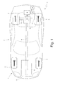
- numeral 1 indicates as a whole a road vehicle with hybrid propulsion provided with two front wheels 2 and two rear drive wheels 3, which receive torque from a hybrid propulsion system 4.
- the hybrid propulsion system 4 comprises an internal combustion engine 5, which is arranged in frontal position and is provided with a drive shaft 6, an automatic manual transmission 7 (commonly named "AMT"), which transmits the torque generated by the internal combustion engine 5 to the rear drive wheels 3, and a reversible electric machine 8 (i.e. an electric machine which can work either as electric motor, using electricity and generating mechanical torque, or as electric generator, using mechanical energy and generating electrical energy), which is mechanically connected to the transmission 7.
- AMT automatic manual transmission 7
- a reversible electric machine 8 i.e. an electric machine which can work either as electric motor, using electricity and generating mechanical torque, or as electric generator, using mechanical energy and generating electrical energy
- Transmission 7 comprises a transmission shaft 9, which, at one end, is angularly integral with the drive shaft 6, and at the other end is mechanically connected to a twin-clutch gearbox 10, which is arranged in rear position and transmits motion to the rear drive wheels 3 by means of two axles shafts 11, which receive motion from a differential 12.
- the reversible electric machine 8 is mechanically connected to the twin-clutch gearbox 10, and is driven by an power electronic converter 13 connected to an electric storage system 14, which is adapted to store electrical energy, and is provided with chemical batteries and/or supercapacitors.
- the chemical batteries have the advantage of providing a high amount of energy but the disadvantage of not being capable of delivering very high electrical power and thus allow the vehicle 1 to cover long distances in electric mode (high autonomy), but do not allow the vehicle 1 to reach high dynamic performance in electric mode; on the contrary, the supercapacitors display the advantage of being able to deliver a very high electrical power but on the contrary are not capable of providing a large amount of energy and thus allow the vehicle 1 to reach high dynamic performance in electric mode, but do not allow the vehicle 1 to cover considerable distances in electric mode.
- the proportion between chemical batteries and supercapacitors in the storage system 14 is chosen during the step of designing according to the desired ratio between autonomy and performance in electric mode.
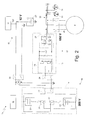
- the vehicle 1 is provided with an electrical power system 15 comprising a storage section 16, which comprises the storage system 14 and works at average voltage equal to 200 Volts nominal.
- the electrical power system 15 of the vehicle 1 comprises a section of traction 17 which interacts with the electric machine 8 and works at high voltage equal to 650 Volts nominal; the section of traction 17 is connected to the storage section 16 by means of a two-way power electronic converter 13 (i.e. that is capable of absorbing electrical power from the storage section for powering the electric machine working as motor or is capable of providing to the storage section the electrical power generated by the electric machine working as generator).
- the electrical system 15 of the vehicle 1 comprises a section of auxiliaries 18 which supplies all the auxiliary services 19 (diagrammatically shown) of the vehicle 1 requiring an electric supply and works at low voltage equal to 12 Volts nominal;
- the section of auxiliaries 18 comprises a buffer battery 20 having a modest storage capacity (when compared to that of the storage system 14) and is electrically powered by the storage section 16 according to the methods described hereinafter for powering the auxiliary services 19 and/or for recharging the buffer battery 20.
- the buffer system 14 comprises two reciprocally independent twin batteries 21 which are connected to one another in series. Furthermore, the storage system 14 comprises, for each battery 21, a respective electronic or electromechanical bypass switch 22, which is connected in parallel to the battery 21 to form a bypass of the battery 21; in case of failure to a battery 21, the battery 21 itself is cut off by closing the respective bypass switch 22 and the storage system 14 continues to work with the other battery 22 only. Furthermore, the storage system 14 comprises an electronic or electromechanical separation switch 23 (which is also shaped as electric disconnector) having, among other, the function of guaranteeing that the electrical system 15 of the vehicle 1 is free from voltage when a service intervention is required.
- the storage section 16 is connected to the section of traction 17 by means of an electronic or electromechanical connection switch 24 and is connected to section 18 of the auxiliary devices by means of an electronic or electromechanical connection switch 25.
- the power electronic converter 13 is provided with a two-way DC-DC converter of the "Buck-Boost" type, which has the function of modifying the voltage to electrically connect the storage system 14, which works at medium voltage (typically 200 Volts when both batteries 21 are working), to the power electronic converter 13, which works at high voltage (typically 650 Volts). Furthermore, the power electronic converter 13 comprises a three-phase inverter 27, which on direct current side is connected to the two-way converter 26 and on alternating current side is connected to the three-phase bars 28.
- a capacitor having the function of reducing the oscillations of the voltage
- a resistor having the function of discharging the capacitor when the circuit is not used to prevent voltage dangerous for technicians carrying out maintenance/repair operations from remaining in the circuit for a long time.
- the electric machine 8 is connected to the three-phase bars 28 by means of an electronic or electromechanical three-phase switch 29. Furthermore, the three-phase bars 28 are connected to a three-phase connector 30 (i.e. provided with three terminals connected to the three three-phase bars 28, respectively) and a one-phase connector 31 (i.e. provided with two terminals connected to one two of the three three-phase bars 28, respectively).
- a three-phase connector 30 i.e. provided with three terminals connected to the three three-phase bars 28, respectively
- a one-phase connector 31 i.e. provided with two terminals connected to one two of the three three-phase bars 28, respectively.
- a control unit 32 is contemplated which has the function of superintending the operation of all components of the electrical power system 15 of vehicle 1, controlling the bypass switches 22, controlling the separation switches 23 and 29, controlling the connection switches 24 and 25, driving the converter 26, and driving the inverter 27.
- both batteries 21 are active and reciprocally connected in series to output a voltage of 200 Volts from the storage system 14 (each battery 21 has a voltage of 100 Volts at its terminals).
- each battery 21 has a voltage of 100 Volts at its terminals.
- the battery 21 itself is excluded by closing the respective bypass switch 22 and the storage system 14 continues to work only with the other battery 21; thus a halved voltage with respect to the nominal value (100 Volts instead of 200 Volts) is provided at the output of the storage system 14 and such halving of the voltage is compensated by appropriately driving the converter 26 so that a nominal voltage equal to 650 Volts is always present at converter output 26.
- the separation switch 29 is closed so that the inverter 27 can drive the electric machine 8 either as motor or as generator.
- the separation switch 29 is opened and the storage system 14 can be recharged by connect the three-phase bars 28 to the electric mains either by means of the three-phase connector 30 or by means of a one-phase connector 31; all three branches of the inverter 27 are active when the three-phase connector 30 is used, while only two of the three branches of the inverter 27 are active when the one-phase connector 31 is used.
- the inverter 27 and the converter 26 are driven so that the input alternating voltage of the mains (normally 220 V between phase and ground and 380 Volts between two phases) is transformed into direct 200 Volts at the terminals of the storage system 14 (100 Volts, if one of the two batteries 21 has been cut off by means of the respective bypass switch 22).
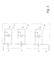
- each battery 21 consists of a plurality of electrochemical cells 33 (only a small part of which is shown in figure 1 ), which are used to convert storage chemical energy into electrical energy and vice versa and connected in series so that the voltage of the single cells is summed.
- the battery 21 has at its terminals a nominal voltage of 100 Volts and comprises twenty-five cells, which are connected to one another in series and each have a nominal voltage of 4 Volts.
- bypass branch 34 In parallel to each cell 33 is arranged a bypass branch 34, which consists of an electronic or electromechanical bypass switch 35 connected in series to a diode 36 and has the function of excluding the cell 33 from the electrical current which crosses the battery 21 when needed.
- the bypass switch 35 of a bypass branch 34 when the bypass switch 35 of a bypass branch 34 is open, the corresponding cell 33 is crossed by the electrical current which crosses the battery 21; instead, when the bypass switch 35 of a bypass branch 34 is closed, the corresponding cell 33 is not crossed by the electrical current which crosses the battery 21 because such a current flows through the bypass branch 34.
- the diode 36 of the bypass branch 34 is needed to avoid short-circuiting the cell 33 when the bypass switch 35 is closed.
- each sensor 38 is provided for each cell 33 which is coupled to the cell 33 to detect in use the state of the charge of the cell 33 itself.
- each sensor 37 is a voltmeter, is connected in parallel to the corresponding cell 33, and measures the voltage present at the terminals of the cells 33 itself; the charge state of the cell 33 itself can be accurately determined according to the voltage present at the terminal of a cell 33 and by applying a law which can be obtained experimentally.
- a temperature sensor which determines the temperature of the cell 33 is also provided; the measurement of a temperature of a cell 33 is used along with the measurement of the voltage present at the terminals of the cell 33 to determine the charge state of the cell 33 itself.
- connection switches 24 and 25 The method used for supplying electrical energy to the section of auxiliaries 18 by means of a particular control type of the connection switches 24 and 25 is described below.
- bypass switches 35 of the bypass branches 34 of the batteries 21 By appropriately driving the bypass switches 35 of the bypass branches 34 of the batteries 21 it is possible to vary the voltage present at the terminals of the batteries 21 and, thus, the voltage present at the terminals of the storage system 14.
- bypass switches 35 when the storage section 16 must be connected to the section of traction 17, all the bypass switches 35 of the bypass branches 34 are open to have at the terminals of the storage system 14 a voltage equal to 200 Volts nominal, instead when the storage section 16 must be connected to the section of auxiliaries 18 only three (or four) bypass switches 35 of the bypass branches 34 are open to have at the terminals of the storage system 14 a voltage equal to 12 Volts (or 16 Volts) nominal (a nominal voltage also slightly higher than 12 Volts may be applied to the buffer battery 20 for recharging the buffer battery 20 itself).
- connection switches 24 and 25 may be both open (typically in case of maintenance), but are never both closed, because the input voltage of the section of traction 17 (200 Volts nominal) is highly different from the input voltage of the section of auxiliaries 18 (12 Volts nominal); in other words, by closing both connection switches 24 and 25, it is impossible to supply the corresponding nominal voltages to both sections 17 and 18, thus by closing both connection switches 24 and 25 of the section of traction 17 a greatly insufficient voltage is applied to the section of traction and/or an excessively high voltage is applied to the section of auxiliaries 18.
- the storage section 16 must be connected only to the section of traction 17 to exchange electrical energy with the section of traction 17, the storage section 16 must be connected only to the section of auxiliaries 18 for providing electrical energy to the section of auxiliaries 18, or the storage section 16 must be connected at the same time to the section of traction 17 and to the section of auxiliaries 18.
- connection switch 24 is closed and the connection switch 24 is opened.
- connection switch 24 is opened and the connection switch 24 is closed.
- the power electronic converter capacitors 13 are capable of compensating for the lack of connection to the storage section 16 by supplying or absorbing electrical energy.
- the buffer battery 20 is capable of compensating for the lack of connection with the storage section 16 by supplying electrical energy.
- the duration of the time intervals A and B is not normally constant and predetermined, but is determined from time to time according to the operating conditions by taking into account, on one hand, the electrical energy exchanging needs of sections 17 and 18 with storage section 16 and, on the other hand, the capacity of sections 17 and 18 to work well in the absence of the connection with the storage section 16. For example, when the buffer battery 20 is very flat, the duration of the time intervals B is extended, or when the electric machine 8 is close to full power then the duration of time intervals A is extended.
- the average duration of the time intervals A and B is comprised from 0.5 to 2 seconds.
- the cells 33 comprising each battery 21 inevitably display differences related to constructive tolerances and to the dispersion of the components used for making the cells 33 themselves; consequently, the capacity (i.e. the amount of electrical charge which may be delivered and commonly expressed in Ampere-hour) of the cells 33 has significant differences which in the currently marketed batteries are of the order of ⁇ 10% with respect to nominal value.
- the capacity of each battery 21 i.e. the series of all the cells 33
- the capacity of each battery 21 is always limited to the lower capacity present (i.e. to the lowest capacity of all the cells 33); thus only the less performing cell 33 is used for the maximum of its performance, while all the other cells 33 are under-used.
- the charge state of each cell 33 is detected by means of the respective sensor 37 coupled to the cell 33 itself; typically, the charge state of a cell 33 is expressed as quantity of charge stored in the cell 33, and such a quantity of charge may be absolute (i.e. measured for example in Ampere-hour) or relative (for example expressed as a percentage with respect to the amount of maximum or nominal charge).
- the charge states of the cells 33 it is determined which cells 33 have the highest charge state (i.e. the most charged cells 33) and thus which cells 33 must be used to power the section of auxiliaries 18.
- a safety voltmeter 38 which measures the electrical voltage upstream of the connection switch 25 and enables the closing of the connection switch 25 only if the electrical voltage upstream of the connection switch 25 is compatible with the nominal electrical voltage of the section of auxiliaries 18 is arranged upstream of the connection switch 25. Furthermore, the safety voltmeter 38 determines the immediate opening of the connection switch 25 if the electrical voltage upstream of the connection switch 25 exceeds the maximum electrical voltage sustainable by the section of auxiliaries 18. The function of the safety voltmeter 38 is to offer a further safety to avoid applying an electrical voltage higher than the maximum sustainable electric voltage the section of auxiliaries 18.
- the two batteries 21 are connected in series to output the voltage of 200 Volts nominal when the storage section 16 must exchange energy with the section of traction 17; instead, when the storage section 16 must feed the section of auxiliaries 18 the two batteries 21 are connected in parallel so as to be able to use six cells 33 (instead of three cells 33) to output the voltage of 12 Volts nominal. In this manner, it is possible to feed double the electrical power from the storage section 16 to the section of auxiliaries 18.
- the storage system 14 comprises one or more series/parallel electronic or electromechanical switches, which are driven to vary the type of connection of the two batteries 21.
- the electrical system 15 described above has many advantages.
- the electrical system 15 described above allows to supply a suitable electrical supply to the section of auxiliaries 18 without using a dedicated electronic converter with an evident saving of costs and, above all, of dimensions and weight.
- the electrical system 15 described above allows to equalize the charge between the cells 33 of each battery 21 without using a dedicated electrical energy management unit (also called equalization unit) which during the operation of the battery 21 has the task of transferring electrical energy between cells 33; in other words, the equalization of the charge of the cells 33 of each battery 21 is not implemented by transferring electrical energy from the most charged cells 33 to the least charged cells 33, but by transferring the electrical energy from the most charged cells 33 to the section of auxiliaries 18. In this manner, the energy efficiency of the batteries 21 is increased (the energy transfer in the cells 33 causes a given dissipation of energy) and the cost of the control unit of the electrical energy is saved.
- a dedicated electrical energy management unit also called equalization unit
Landscapes
- Engineering & Computer Science (AREA)
- Power Engineering (AREA)
- Transportation (AREA)
- Mechanical Engineering (AREA)
- Life Sciences & Earth Sciences (AREA)
- Sustainable Development (AREA)
- Sustainable Energy (AREA)
- Chemical & Material Sciences (AREA)
- Combustion & Propulsion (AREA)
- Electric Propulsion And Braking For Vehicles (AREA)
- Charge And Discharge Circuits For Batteries Or The Like (AREA)
Applications Claiming Priority (1)
| Application Number | Priority Date | Filing Date | Title |
|---|---|---|---|
| ITBO2010A000209A IT1399313B1 (it) | 2010-04-07 | 2010-04-07 | Impianto elettrico di un veicolo stradale con propulsione elettrica e relativo metodo di controllo |
Publications (3)
| Publication Number | Publication Date |
|---|---|
| EP2374651A2 true EP2374651A2 (fr) | 2011-10-12 |
| EP2374651A3 EP2374651A3 (fr) | 2017-03-01 |
| EP2374651B1 EP2374651B1 (fr) | 2018-01-31 |
Family
ID=43572186
Family Applications (1)
| Application Number | Title | Priority Date | Filing Date |
|---|---|---|---|
| EP11161585.2A Active EP2374651B1 (fr) | 2010-04-07 | 2011-04-07 | Système électrique pour véhicule à propulsion électrique et son procédé de commande |
Country Status (3)
| Country | Link |
|---|---|
| US (1) | US9006920B2 (fr) |
| EP (1) | EP2374651B1 (fr) |
| IT (1) | IT1399313B1 (fr) |
Cited By (7)
| Publication number | Priority date | Publication date | Assignee | Title |
|---|---|---|---|---|
| FR2986120A1 (fr) * | 2012-01-23 | 2013-07-26 | Commissariat Energie Atomique | Gestion combinee de deux sources de tension |
| EP2810815A1 (fr) * | 2013-06-07 | 2014-12-10 | Flextronics International Kft. | Système d'accumulation d'énergie et procédé d'ajustement de la tension d'un accumulateur d'énergie |
| EP2879266A1 (fr) * | 2013-11-28 | 2015-06-03 | Dialog Semiconductor GmbH | Procédé de gestion de puissance pour une batterie rechargeable à cellules empilées et batterie rechargeable à cellules empilées |
| ITUB20153296A1 (it) * | 2015-08-17 | 2015-11-17 | Marco Algozzino | Cambio elettronico per veicoli elettrici |
| WO2019215145A1 (fr) * | 2018-05-09 | 2019-11-14 | Robert Bosch Gmbh | Dispositif de commutation servant à charger une batterie d'un véhicule électrique sur des infrastructures de charge à cc actuelles et futures et procédé servant à faire fonctionner le dispositif de commutation |
| EP3799244A4 (fr) * | 2018-06-13 | 2021-08-18 | NR Electric Co., Ltd. | Convertisseur séparé d'unité de stockage d'énergie, système d'application associé et procédé de commande associé |
| CN117818383A (zh) * | 2024-03-06 | 2024-04-05 | 山东科技大学 | 一种车用复合电池系统及其能量控制方法 |
Families Citing this family (18)
| Publication number | Priority date | Publication date | Assignee | Title |
|---|---|---|---|---|
| US20130088184A1 (en) * | 2011-10-06 | 2013-04-11 | Fu-Tzu HSU | Battery device utilizing oxidation and reduction reactions to produce electric potential |
| WO2013097821A1 (fr) * | 2011-12-31 | 2013-07-04 | 深圳市比亚迪汽车研发有限公司 | Voiture électrique et son système d'alimentation électrique extérieur |
| WO2013160014A1 (fr) * | 2012-04-27 | 2013-10-31 | Borgwarner Torqtransfer Systems Ab | Essieu électrique |
| US9627999B2 (en) * | 2012-11-07 | 2017-04-18 | Volvo Truck Corporation | Power supply device |
| DE102012220549A1 (de) * | 2012-11-12 | 2014-05-15 | Siemens Aktiengesellschaft | Elektro-Transportmittel, zugehöriges Verfahren und zugehöriger Akkumulator |
| JP2014131404A (ja) * | 2012-12-28 | 2014-07-10 | Suzuki Motor Corp | 車両用充電装置 |
| US10106038B2 (en) * | 2012-12-28 | 2018-10-23 | Johnson Controls Technology Company | Dual function battery system and method |
| JP6118222B2 (ja) * | 2013-09-26 | 2017-04-19 | 富士重工業株式会社 | 車両用電源装置 |
| JP5730975B2 (ja) * | 2013-10-11 | 2015-06-10 | 富士重工業株式会社 | 電動車両 |
| DE102015004119A1 (de) * | 2015-03-31 | 2016-10-06 | Audi Ag | Kraftfahrzeug mit einem elektrischen Energiespeicher und zwei Ladeschnittstellen, Ladesystem sowie Verfahren |
| GB2541352B (en) * | 2015-04-30 | 2022-02-16 | Porsche Ag | Apparatus and method for an electric power supply |
| JP6928347B2 (ja) * | 2017-08-02 | 2021-09-01 | NExT−e Solutions株式会社 | 管理装置、蓄電装置、蓄電システム、及び、電気機器 |
| DE102017222192A1 (de) * | 2017-12-07 | 2019-06-13 | Audi Ag | HV-Batterieanordnung für ein Kraftfahrzeug, Bordnetz, Kraftfahrzeug und Verfahren zum Steuern einer HV-Batterieanordnung |
| JP7056513B2 (ja) * | 2018-10-26 | 2022-04-19 | トヨタ自動車株式会社 | 電池制御装置 |
| US10766371B1 (en) * | 2019-02-22 | 2020-09-08 | Ford Global Technologies, Llc | System and method to improve range and fuel economy of electrified vehicles using life balancing |
| IT201900005664A1 (it) * | 2019-04-12 | 2020-10-12 | Ferrari Spa | Impianto elettrico di un veicolo stradale provvisto di un convertitore elettronico di potenza dc-dc |
| US20210380054A1 (en) * | 2020-06-04 | 2021-12-09 | Transportation Ip Holdings, Llc | Electric supply system |
| DE102020126989A1 (de) | 2020-10-14 | 2022-04-14 | Audi Aktiengesellschaft | Steuereinrichtung zum Steuern einer Batterie eines Bordnetzes für ein Kraftfahrzeug, Bordnetz, Kraftfahrzeug und Verfahren zum Steuern einer Batterie |
Citations (1)
| Publication number | Priority date | Publication date | Assignee | Title |
|---|---|---|---|---|
| EP2056422A1 (fr) | 2007-11-01 | 2009-05-06 | Honda Motor Co., Ltd. | Système de commande de décharge d'une batterie |
Family Cites Families (7)
| Publication number | Priority date | Publication date | Assignee | Title |
|---|---|---|---|---|
| JP2003189490A (ja) * | 2001-12-14 | 2003-07-04 | Honda Motor Co Ltd | 蓄電装置の残容量均等化装置 |
| JP2007228753A (ja) * | 2006-02-24 | 2007-09-06 | Toyota Motor Corp | 電動車両 |
| JP4569603B2 (ja) * | 2007-01-04 | 2010-10-27 | トヨタ自動車株式会社 | 電源システムおよびそれを備える車両、ならびにその制御方法 |
| JP4734268B2 (ja) * | 2007-02-13 | 2011-07-27 | プライムアースEvエナジー株式会社 | 放電システム、および電動車両 |
| WO2008149475A1 (fr) * | 2007-06-08 | 2008-12-11 | Panasonic Corporation | Système d'alimentation et procédé de commande de batterie assemblée |
| US7973514B2 (en) * | 2007-10-09 | 2011-07-05 | O2Micro, Inc. | Battery cell balancing systems using current regulators |
| JP4305553B2 (ja) * | 2007-10-23 | 2009-07-29 | トヨタ自動車株式会社 | 電動車両 |
-
2010
- 2010-04-07 IT ITBO2010A000209A patent/IT1399313B1/it active
-
2011
- 2011-04-07 EP EP11161585.2A patent/EP2374651B1/fr active Active
- 2011-04-07 US US13/081,697 patent/US9006920B2/en active Active
Patent Citations (1)
| Publication number | Priority date | Publication date | Assignee | Title |
|---|---|---|---|---|
| EP2056422A1 (fr) | 2007-11-01 | 2009-05-06 | Honda Motor Co., Ltd. | Système de commande de décharge d'une batterie |
Cited By (11)
| Publication number | Priority date | Publication date | Assignee | Title |
|---|---|---|---|---|
| FR2986120A1 (fr) * | 2012-01-23 | 2013-07-26 | Commissariat Energie Atomique | Gestion combinee de deux sources de tension |
| WO2013110649A3 (fr) * | 2012-01-23 | 2014-12-04 | Commissariat A L'energie Atomique Et Aux Energies Alternatives | Gestion combinee de deux sources de tension |
| US9948095B2 (en) | 2012-01-23 | 2018-04-17 | Commissariat A L'energie Atomique Et Aux Energies Alternatives | Combined control of two voltage sources |
| EP3604020A1 (fr) * | 2012-01-23 | 2020-02-05 | Commissariat à l'Energie Atomique et aux Energies Alternatives | Gestion combinée de deux sources de tension |
| EP2810815A1 (fr) * | 2013-06-07 | 2014-12-10 | Flextronics International Kft. | Système d'accumulation d'énergie et procédé d'ajustement de la tension d'un accumulateur d'énergie |
| EP2879266A1 (fr) * | 2013-11-28 | 2015-06-03 | Dialog Semiconductor GmbH | Procédé de gestion de puissance pour une batterie rechargeable à cellules empilées et batterie rechargeable à cellules empilées |
| ITUB20153296A1 (it) * | 2015-08-17 | 2015-11-17 | Marco Algozzino | Cambio elettronico per veicoli elettrici |
| WO2019215145A1 (fr) * | 2018-05-09 | 2019-11-14 | Robert Bosch Gmbh | Dispositif de commutation servant à charger une batterie d'un véhicule électrique sur des infrastructures de charge à cc actuelles et futures et procédé servant à faire fonctionner le dispositif de commutation |
| EP3799244A4 (fr) * | 2018-06-13 | 2021-08-18 | NR Electric Co., Ltd. | Convertisseur séparé d'unité de stockage d'énergie, système d'application associé et procédé de commande associé |
| CN117818383A (zh) * | 2024-03-06 | 2024-04-05 | 山东科技大学 | 一种车用复合电池系统及其能量控制方法 |
| CN117818383B (zh) * | 2024-03-06 | 2024-04-30 | 山东科技大学 | 一种车用复合电池系统及其能量控制方法 |
Also Published As
| Publication number | Publication date |
|---|---|
| US9006920B2 (en) | 2015-04-14 |
| ITBO20100209A1 (it) | 2011-10-08 |
| IT1399313B1 (it) | 2013-04-16 |
| US20120001480A1 (en) | 2012-01-05 |
| EP2374651B1 (fr) | 2018-01-31 |
| EP2374651A3 (fr) | 2017-03-01 |
Similar Documents
| Publication | Publication Date | Title |
|---|---|---|
| EP2374651B1 (fr) | Système électrique pour véhicule à propulsion électrique et son procédé de commande | |
| US10128674B2 (en) | Apparatus and method for charging and discharging a multiple battery system | |
| US9643498B2 (en) | Method for recharging a pair of vehicle batteries of different nominal voltages, and associated system | |
| US7984776B2 (en) | Energy storage and control system for a vehicle electrified drivetrain | |
| CN110678357B (zh) | 用于提供不同类型电压的具有分别与转换模块相关联的单体蓄电池组的电池 | |
| US8860359B2 (en) | Hybrid energy storage system | |
| CN106926718B (zh) | 用于对多个能量存储装置充电的方法和设备 | |
| JP3176361U (ja) | フォールトトレラントモジュール電池管理システム | |
| CN102652387B (zh) | 能量存储系统及其运行方法 | |
| CN106394271B (zh) | 用于直流快速充电的高电压电池接触器布置 | |
| US6127798A (en) | Electric power supply having two electrical battery storage means for vehicles and other applications | |
| US8084988B2 (en) | Power supply system | |
| US9935471B2 (en) | Drive apparatus and transporter | |
| CN102832657B (zh) | 电池管理系统及电池管理方法 | |
| EP3232049B1 (fr) | Système de commande de démarrage de véhicule automobile et véhicule automobile | |
| CN103390913B (zh) | 具有多个安置在多个蓄电池组中的蓄电池模块的蓄电池 | |
| KR101959498B1 (ko) | 풍력 기반 부하 분리 전기 충전 시스템 | |
| CN104661856A (zh) | 用于机动车的耦合蓄能器设备 | |
| CN104254458B (zh) | 用于对电驱动装置供给电流的装置和方法 | |
| CA2884684C (fr) | Appareil permettant de stocker et de liberer de l'energie electrique au moyen d'un volant et d'une pluralite d'accumulateurs electrochimiques | |
| EP2409376A1 (fr) | Systeme et procede permettant la commande d'une unite de stockage d'energie | |
| CN114340936A (zh) | 一种车辆和一种用于运行车辆的方法 | |
| CN110803021A (zh) | 用于控制电动化车辆辅助电池的充电的系统及方法 | |
| US20240253524A1 (en) | Method for fast charging electric vehicle battery | |
| CN118372703A (zh) | 具有混合能源智能调度的充电系统和电动汽车充电方法 |
Legal Events
| Date | Code | Title | Description |
|---|---|---|---|
| PUAI | Public reference made under article 153(3) epc to a published international application that has entered the european phase |
Free format text: ORIGINAL CODE: 0009012 |
|
| AK | Designated contracting states |
Kind code of ref document: A2 Designated state(s): AL AT BE BG CH CY CZ DE DK EE ES FI FR GB GR HR HU IE IS IT LI LT LU LV MC MK MT NL NO PL PT RO RS SE SI SK SM TR |
|
| AX | Request for extension of the european patent |
Extension state: BA ME |
|
| PUAL | Search report despatched |
Free format text: ORIGINAL CODE: 0009013 |
|
| AK | Designated contracting states |
Kind code of ref document: A3 Designated state(s): AL AT BE BG CH CY CZ DE DK EE ES FI FR GB GR HR HU IE IS IT LI LT LU LV MC MK MT NL NO PL PT RO RS SE SI SK SM TR |
|
| AX | Request for extension of the european patent |
Extension state: BA ME |
|
| RIC1 | Information provided on ipc code assigned before grant |
Ipc: B60L 11/14 20060101ALI20170126BHEP Ipc: H02J 7/00 20060101ALI20170126BHEP Ipc: H02J 7/14 20060101ALI20170126BHEP Ipc: B60L 11/12 20060101AFI20170126BHEP Ipc: B60K 6/48 20071001ALI20170126BHEP Ipc: B60L 11/00 20060101ALI20170126BHEP Ipc: B60L 3/00 20060101ALI20170126BHEP Ipc: B60L 3/04 20060101ALI20170126BHEP Ipc: B60L 11/18 20060101ALI20170126BHEP Ipc: B60L 15/00 20060101ALI20170126BHEP |
|
| 17P | Request for examination filed |
Effective date: 20170210 |
|
| GRAP | Despatch of communication of intention to grant a patent |
Free format text: ORIGINAL CODE: EPIDOSNIGR1 |
|
| INTG | Intention to grant announced |
Effective date: 20170825 |
|
| GRAS | Grant fee paid |
Free format text: ORIGINAL CODE: EPIDOSNIGR3 |
|
| GRAA | (expected) grant |
Free format text: ORIGINAL CODE: 0009210 |
|
| AK | Designated contracting states |
Kind code of ref document: B1 Designated state(s): AL AT BE BG CH CY CZ DE DK EE ES FI FR GB GR HR HU IE IS IT LI LT LU LV MC MK MT NL NO PL PT RO RS SE SI SK SM TR |
|
| REG | Reference to a national code |
Ref country code: GB Ref legal event code: FG4D Ref country code: CH Ref legal event code: EP |
|
| REG | Reference to a national code |
Ref country code: AT Ref legal event code: REF Ref document number: 967028 Country of ref document: AT Kind code of ref document: T Effective date: 20180215 |
|
| REG | Reference to a national code |
Ref country code: IE Ref legal event code: FG4D |
|
| REG | Reference to a national code |
Ref country code: DE Ref legal event code: R096 Ref document number: 602011045432 Country of ref document: DE |
|
| REG | Reference to a national code |
Ref country code: NL Ref legal event code: MP Effective date: 20180131 |
|
| REG | Reference to a national code |
Ref country code: LT Ref legal event code: MG4D |
|
| REG | Reference to a national code |
Ref country code: AT Ref legal event code: MK05 Ref document number: 967028 Country of ref document: AT Kind code of ref document: T Effective date: 20180131 |
|
| PG25 | Lapsed in a contracting state [announced via postgrant information from national office to epo] |
Ref country code: LT Free format text: LAPSE BECAUSE OF FAILURE TO SUBMIT A TRANSLATION OF THE DESCRIPTION OR TO PAY THE FEE WITHIN THE PRESCRIBED TIME-LIMIT Effective date: 20180131 Ref country code: NO Free format text: LAPSE BECAUSE OF FAILURE TO SUBMIT A TRANSLATION OF THE DESCRIPTION OR TO PAY THE FEE WITHIN THE PRESCRIBED TIME-LIMIT Effective date: 20180430 Ref country code: ES Free format text: LAPSE BECAUSE OF FAILURE TO SUBMIT A TRANSLATION OF THE DESCRIPTION OR TO PAY THE FEE WITHIN THE PRESCRIBED TIME-LIMIT Effective date: 20180131 Ref country code: NL Free format text: LAPSE BECAUSE OF FAILURE TO SUBMIT A TRANSLATION OF THE DESCRIPTION OR TO PAY THE FEE WITHIN THE PRESCRIBED TIME-LIMIT Effective date: 20180131 Ref country code: HR Free format text: LAPSE BECAUSE OF FAILURE TO SUBMIT A TRANSLATION OF THE DESCRIPTION OR TO PAY THE FEE WITHIN THE PRESCRIBED TIME-LIMIT Effective date: 20180131 Ref country code: FI Free format text: LAPSE BECAUSE OF FAILURE TO SUBMIT A TRANSLATION OF THE DESCRIPTION OR TO PAY THE FEE WITHIN THE PRESCRIBED TIME-LIMIT Effective date: 20180131 |
|
| PG25 | Lapsed in a contracting state [announced via postgrant information from national office to epo] |
Ref country code: PL Free format text: LAPSE BECAUSE OF FAILURE TO SUBMIT A TRANSLATION OF THE DESCRIPTION OR TO PAY THE FEE WITHIN THE PRESCRIBED TIME-LIMIT Effective date: 20180131 Ref country code: GR Free format text: LAPSE BECAUSE OF FAILURE TO SUBMIT A TRANSLATION OF THE DESCRIPTION OR TO PAY THE FEE WITHIN THE PRESCRIBED TIME-LIMIT Effective date: 20180501 Ref country code: BG Free format text: LAPSE BECAUSE OF FAILURE TO SUBMIT A TRANSLATION OF THE DESCRIPTION OR TO PAY THE FEE WITHIN THE PRESCRIBED TIME-LIMIT Effective date: 20180430 Ref country code: LV Free format text: LAPSE BECAUSE OF FAILURE TO SUBMIT A TRANSLATION OF THE DESCRIPTION OR TO PAY THE FEE WITHIN THE PRESCRIBED TIME-LIMIT Effective date: 20180131 Ref country code: AT Free format text: LAPSE BECAUSE OF FAILURE TO SUBMIT A TRANSLATION OF THE DESCRIPTION OR TO PAY THE FEE WITHIN THE PRESCRIBED TIME-LIMIT Effective date: 20180131 Ref country code: RS Free format text: LAPSE BECAUSE OF FAILURE TO SUBMIT A TRANSLATION OF THE DESCRIPTION OR TO PAY THE FEE WITHIN THE PRESCRIBED TIME-LIMIT Effective date: 20180131 Ref country code: SE Free format text: LAPSE BECAUSE OF FAILURE TO SUBMIT A TRANSLATION OF THE DESCRIPTION OR TO PAY THE FEE WITHIN THE PRESCRIBED TIME-LIMIT Effective date: 20180131 Ref country code: IS Free format text: LAPSE BECAUSE OF FAILURE TO SUBMIT A TRANSLATION OF THE DESCRIPTION OR TO PAY THE FEE WITHIN THE PRESCRIBED TIME-LIMIT Effective date: 20180531 |
|
| PG25 | Lapsed in a contracting state [announced via postgrant information from national office to epo] |
Ref country code: AL Free format text: LAPSE BECAUSE OF FAILURE TO SUBMIT A TRANSLATION OF THE DESCRIPTION OR TO PAY THE FEE WITHIN THE PRESCRIBED TIME-LIMIT Effective date: 20180131 Ref country code: RO Free format text: LAPSE BECAUSE OF FAILURE TO SUBMIT A TRANSLATION OF THE DESCRIPTION OR TO PAY THE FEE WITHIN THE PRESCRIBED TIME-LIMIT Effective date: 20180131 Ref country code: EE Free format text: LAPSE BECAUSE OF FAILURE TO SUBMIT A TRANSLATION OF THE DESCRIPTION OR TO PAY THE FEE WITHIN THE PRESCRIBED TIME-LIMIT Effective date: 20180131 |
|
| REG | Reference to a national code |
Ref country code: DE Ref legal event code: R097 Ref document number: 602011045432 Country of ref document: DE |
|
| PG25 | Lapsed in a contracting state [announced via postgrant information from national office to epo] |
Ref country code: CZ Free format text: LAPSE BECAUSE OF FAILURE TO SUBMIT A TRANSLATION OF THE DESCRIPTION OR TO PAY THE FEE WITHIN THE PRESCRIBED TIME-LIMIT Effective date: 20180131 Ref country code: SM Free format text: LAPSE BECAUSE OF FAILURE TO SUBMIT A TRANSLATION OF THE DESCRIPTION OR TO PAY THE FEE WITHIN THE PRESCRIBED TIME-LIMIT Effective date: 20180131 Ref country code: DK Free format text: LAPSE BECAUSE OF FAILURE TO SUBMIT A TRANSLATION OF THE DESCRIPTION OR TO PAY THE FEE WITHIN THE PRESCRIBED TIME-LIMIT Effective date: 20180131 Ref country code: SK Free format text: LAPSE BECAUSE OF FAILURE TO SUBMIT A TRANSLATION OF THE DESCRIPTION OR TO PAY THE FEE WITHIN THE PRESCRIBED TIME-LIMIT Effective date: 20180131 Ref country code: MC Free format text: LAPSE BECAUSE OF FAILURE TO SUBMIT A TRANSLATION OF THE DESCRIPTION OR TO PAY THE FEE WITHIN THE PRESCRIBED TIME-LIMIT Effective date: 20180131 |
|
| REG | Reference to a national code |
Ref country code: CH Ref legal event code: PL |
|
| PLBE | No opposition filed within time limit |
Free format text: ORIGINAL CODE: 0009261 |
|
| STAA | Information on the status of an ep patent application or granted ep patent |
Free format text: STATUS: NO OPPOSITION FILED WITHIN TIME LIMIT |
|
| REG | Reference to a national code |
Ref country code: BE Ref legal event code: MM Effective date: 20180430 |
|
| 26N | No opposition filed |
Effective date: 20181102 |
|
| REG | Reference to a national code |
Ref country code: IE Ref legal event code: MM4A |
|
| PG25 | Lapsed in a contracting state [announced via postgrant information from national office to epo] |
Ref country code: LU Free format text: LAPSE BECAUSE OF NON-PAYMENT OF DUE FEES Effective date: 20180407 |
|
| RIC2 | Information provided on ipc code assigned after grant |
Ipc: H02J 7/00 20060101ALI20170126BHEP Ipc: H02J 7/14 20060101ALI20170126BHEP Ipc: B60K 6/48 20071001ALI20170126BHEP Ipc: B60L 11/18 20060101ALI20170126BHEP Ipc: B60L 11/12 20060101AFI20170126BHEP Ipc: B60L 11/00 20060101ALI20170126BHEP Ipc: B60L 15/00 20060101ALI20170126BHEP Ipc: B60L 11/14 20060101ALI20170126BHEP Ipc: B60L 3/04 20060101ALI20170126BHEP Ipc: B60L 3/00 20190101ALI20170126BHEP |
|
| PG25 | Lapsed in a contracting state [announced via postgrant information from national office to epo] |
Ref country code: LI Free format text: LAPSE BECAUSE OF NON-PAYMENT OF DUE FEES Effective date: 20180430 Ref country code: BE Free format text: LAPSE BECAUSE OF NON-PAYMENT OF DUE FEES Effective date: 20180430 Ref country code: CH Free format text: LAPSE BECAUSE OF NON-PAYMENT OF DUE FEES Effective date: 20180430 Ref country code: SI Free format text: LAPSE BECAUSE OF FAILURE TO SUBMIT A TRANSLATION OF THE DESCRIPTION OR TO PAY THE FEE WITHIN THE PRESCRIBED TIME-LIMIT Effective date: 20180131 |
|
| PG25 | Lapsed in a contracting state [announced via postgrant information from national office to epo] |
Ref country code: FR Free format text: LAPSE BECAUSE OF NON-PAYMENT OF DUE FEES Effective date: 20180430 Ref country code: IE Free format text: LAPSE BECAUSE OF NON-PAYMENT OF DUE FEES Effective date: 20180407 |
|
| PG25 | Lapsed in a contracting state [announced via postgrant information from national office to epo] |
Ref country code: MT Free format text: LAPSE BECAUSE OF NON-PAYMENT OF DUE FEES Effective date: 20180407 |
|
| PG25 | Lapsed in a contracting state [announced via postgrant information from national office to epo] |
Ref country code: TR Free format text: LAPSE BECAUSE OF FAILURE TO SUBMIT A TRANSLATION OF THE DESCRIPTION OR TO PAY THE FEE WITHIN THE PRESCRIBED TIME-LIMIT Effective date: 20180131 |
|
| PG25 | Lapsed in a contracting state [announced via postgrant information from national office to epo] |
Ref country code: PT Free format text: LAPSE BECAUSE OF FAILURE TO SUBMIT A TRANSLATION OF THE DESCRIPTION OR TO PAY THE FEE WITHIN THE PRESCRIBED TIME-LIMIT Effective date: 20180131 Ref country code: HU Free format text: LAPSE BECAUSE OF FAILURE TO SUBMIT A TRANSLATION OF THE DESCRIPTION OR TO PAY THE FEE WITHIN THE PRESCRIBED TIME-LIMIT; INVALID AB INITIO Effective date: 20110407 |
|
| PG25 | Lapsed in a contracting state [announced via postgrant information from national office to epo] |
Ref country code: MK Free format text: LAPSE BECAUSE OF NON-PAYMENT OF DUE FEES Effective date: 20180131 Ref country code: CY Free format text: LAPSE BECAUSE OF FAILURE TO SUBMIT A TRANSLATION OF THE DESCRIPTION OR TO PAY THE FEE WITHIN THE PRESCRIBED TIME-LIMIT Effective date: 20180131 |
|
| P01 | Opt-out of the competence of the unified patent court (upc) registered |
Effective date: 20230525 |
|
| PGFP | Annual fee paid to national office [announced via postgrant information from national office to epo] |
Ref country code: GB Payment date: 20240423 Year of fee payment: 14 |
|
| PGFP | Annual fee paid to national office [announced via postgrant information from national office to epo] |
Ref country code: DE Payment date: 20240429 Year of fee payment: 14 |
|
| PGFP | Annual fee paid to national office [announced via postgrant information from national office to epo] |
Ref country code: IT Payment date: 20240411 Year of fee payment: 14 |