EP2373518B1 - Verriegelungsvorrichtung zum verriegeln eines bauteils an einer tragstruktur - Google Patents
Verriegelungsvorrichtung zum verriegeln eines bauteils an einer tragstruktur Download PDFInfo
- Publication number
- EP2373518B1 EP2373518B1 EP10701889.7A EP10701889A EP2373518B1 EP 2373518 B1 EP2373518 B1 EP 2373518B1 EP 10701889 A EP10701889 A EP 10701889A EP 2373518 B1 EP2373518 B1 EP 2373518B1
- Authority
- EP
- European Patent Office
- Prior art keywords
- locking
- locking device
- support structure
- movement
- hand wheel
- Prior art date
- Legal status (The legal status is an assumption and is not a legal conclusion. Google has not performed a legal analysis and makes no representation as to the accuracy of the status listed.)
- Active
Links
Images

Classifications
-
- B—PERFORMING OPERATIONS; TRANSPORTING
- B60—VEHICLES IN GENERAL
- B60N—SEATS SPECIALLY ADAPTED FOR VEHICLES; VEHICLE PASSENGER ACCOMMODATION NOT OTHERWISE PROVIDED FOR
- B60N2/00—Seats specially adapted for vehicles; Arrangement or mounting of seats in vehicles
- B60N2/005—Arrangement or mounting of seats in vehicles, e.g. dismountable auxiliary seats
- B60N2/015—Attaching seats directly to vehicle chassis
- B60N2/01508—Attaching seats directly to vehicle chassis using quick release attachments
- B60N2/01516—Attaching seats directly to vehicle chassis using quick release attachments with locking mechanisms
- B60N2/01558—Attaching seats directly to vehicle chassis using quick release attachments with locking mechanisms with key and slot
- B60N2/01566—Attaching seats directly to vehicle chassis using quick release attachments with locking mechanisms with key and slot key rotating about a vertical axis
-
- B—PERFORMING OPERATIONS; TRANSPORTING
- B60—VEHICLES IN GENERAL
- B60N—SEATS SPECIALLY ADAPTED FOR VEHICLES; VEHICLE PASSENGER ACCOMMODATION NOT OTHERWISE PROVIDED FOR
- B60N2/00—Seats specially adapted for vehicles; Arrangement or mounting of seats in vehicles
- B60N2/005—Arrangement or mounting of seats in vehicles, e.g. dismountable auxiliary seats
- B60N2/01—Arrangement of seats relative to one another
-
- B—PERFORMING OPERATIONS; TRANSPORTING
- B60—VEHICLES IN GENERAL
- B60N—SEATS SPECIALLY ADAPTED FOR VEHICLES; VEHICLE PASSENGER ACCOMMODATION NOT OTHERWISE PROVIDED FOR
- B60N2/00—Seats specially adapted for vehicles; Arrangement or mounting of seats in vehicles
- B60N2/005—Arrangement or mounting of seats in vehicles, e.g. dismountable auxiliary seats
- B60N2/015—Attaching seats directly to vehicle chassis
- B60N2/01508—Attaching seats directly to vehicle chassis using quick release attachments
- B60N2/01516—Attaching seats directly to vehicle chassis using quick release attachments with locking mechanisms
- B60N2/01525—Attaching seats directly to vehicle chassis using quick release attachments with locking mechanisms with locking elements expanding inside or under the vehicle floor or rail
- B60N2/01541—Attaching seats directly to vehicle chassis using quick release attachments with locking mechanisms with locking elements expanding inside or under the vehicle floor or rail using moving hooks
-
- B—PERFORMING OPERATIONS; TRANSPORTING
- B60—VEHICLES IN GENERAL
- B60N—SEATS SPECIALLY ADAPTED FOR VEHICLES; VEHICLE PASSENGER ACCOMMODATION NOT OTHERWISE PROVIDED FOR
- B60N2/00—Seats specially adapted for vehicles; Arrangement or mounting of seats in vehicles
- B60N2/24—Seats specially adapted for vehicles; Arrangement or mounting of seats in vehicles for particular purposes or particular vehicles
-
- B—PERFORMING OPERATIONS; TRANSPORTING
- B60—VEHICLES IN GENERAL
- B60N—SEATS SPECIALLY ADAPTED FOR VEHICLES; VEHICLE PASSENGER ACCOMMODATION NOT OTHERWISE PROVIDED FOR
- B60N2/00—Seats specially adapted for vehicles; Arrangement or mounting of seats in vehicles
- B60N2/68—Seat frames
-
- B—PERFORMING OPERATIONS; TRANSPORTING
- B60—VEHICLES IN GENERAL
- B60P—VEHICLES ADAPTED FOR LOAD TRANSPORTATION OR TO TRANSPORT, TO CARRY, OR TO COMPRISE SPECIAL LOADS OR OBJECTS
- B60P3/00—Vehicles adapted to transport, to carry or to comprise special loads or objects
- B60P3/42—Vehicles adapted to transport, to carry or to comprise special loads or objects convertible from one use to a different one
- B60P3/423—Vehicles adapted to transport, to carry or to comprise special loads or objects convertible from one use to a different one from transport of persons to transport of goods
-
- B—PERFORMING OPERATIONS; TRANSPORTING
- B60—VEHICLES IN GENERAL
- B60P—VEHICLES ADAPTED FOR LOAD TRANSPORTATION OR TO TRANSPORT, TO CARRY, OR TO COMPRISE SPECIAL LOADS OR OBJECTS
- B60P7/00—Securing or covering of load on vehicles
- B60P7/06—Securing of load
- B60P7/13—Securing freight containers or forwarding containers on vehicles
- B60P7/132—Securing freight containers or forwarding containers on vehicles twist-locks for containers or frames
-
- B—PERFORMING OPERATIONS; TRANSPORTING
- B60—VEHICLES IN GENERAL
- B60N—SEATS SPECIALLY ADAPTED FOR VEHICLES; VEHICLE PASSENGER ACCOMMODATION NOT OTHERWISE PROVIDED FOR
- B60N2205/00—General mechanical or structural details
- B60N2205/20—Measures for elimination or compensation of play or backlash
Definitions
- This invention relates to a locking device and, more especially, this invention relates to a locking device for locking an object on a support structure.
- the locking device may be especially useful for locking cargo on a support structure in the form of a flat platform on a vehicle.
- Locking devices are known for locking an object on a support structure.
- the locking devices are such that the object is rigidly fixed to the support structure.
- EP 0 992 605 A2 discloses a furniture anchorage, particularly for seats which is designed to cooperate with a floor track.
- a bar or tube overlies the floor track and has inverted mushroom studs.
- the heads of the mushroom studs enter the floor track through apertures in the track.
- the heads of the mushroom studs engage under the lips of slots in the floor track. Locking means are also disclosed.
- Another locking device is known from DE 32 06 319 A1 and discloses a first locking means with a spindle 1 which terminates in a spigot 6 and a second locking means with a handle 3 which is attached on a pivot at the other end of the spindle 1.
- the present invention provides a locking device for locking an object on a support structure, which locking device comprises a fork arrangement for engaging an upper part of the object from an edge of the upper part of the object, first locking means for locking the fork arrangement to the object in a horizontal plane, second locking means for locking the fork arrangement to the object in a vertical plane, and movement-permitting means which permits vertical movement in the locking device, the vertical movement being sufficient to allow the support structure to flex so as to prevent the flexing of the support structure acting through the locking device and damaging the object, but with the vertical movement being insufficient adversely to affect secure locking of the object on the support structure by the locking device, wherein
- the object may be any object on any support structure that may flex during operational conditions.
- the object may be cargo on a support structure in the form of a platform on a back of a vehicle.
- the vehicle may be a road vehicle and the road vehicle may be a military road vehicle. With military road vehicles, the cargo may be a frame having seats for military personnel to be carried by the vehicle.
- the movement-permitting means will be such that the vertical movement takes place in the second locking means.
- the movement-permitting means may be a spring.
- the spring is preferably a coil spring but other types of spring may be employed.
- the movement-permitting means may alternatively be a washer having a spring facility.
- the washer is preferably a bevel washer but other types of washer having a spring facility may be employed.
- Movement-permitting means other than a spring or a washer may also be employed.
- the hand wheel may have peripheral formations for providing a hand grip.
- the hand wheel may be provided with apertures for lightening the weight of the hand wheel.
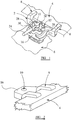
- a locking device 2 for locking an object 4 to a support structure 6.
- the locking device 2 comprises a fork arrangement 8 for engaging an upper part of the object 4 from an edge of the upper part of the object 4 as shown.
- the locking device 2 also comprises first locking means 10 for locking the fork arrangement 8 to the object 4 in a horizontal plane.
- the locking device 2 further comprises second locking means 12 for locking the fork arrangement 8 to the object 4 in a vertical plane.
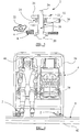
- the locking device 2 further comprises movement-permitting means 14 (see Figure 3 ) which permits vertical movement in the locking device 2.
- the vertical movement is sufficient to allow the support structure 6 to flex so as to prevent the flexing of the support structure 6 acting through the locking device 2 and damaging the object 4.
- the vertical movement is insufficient adversely to affect secure locking of the object 4 on the support structure 6 by the locking device 2.
- the locking device 2 will rigidly lock the object 4 to the support structure 6. Only during adverse conditions causing the support structure 6 to flex will the movement-permitting means 14 come into operation.
- the movement-permitting means 14 When the movement-permitting means 14 comes into operation, it will allow the flexing of the support structure 6 to be absorbed by the locking device 2 because the vertical movement will take place in the locking device 2 and more specifically will take place in the second locking means 12. The vertical movement will be very small and it will not be sufficient adversely to affect secure locking of the object 4 on the support structure 6. Once the conditions causing the support structure 6 to flex have passed, then the movement-permitting means 14 will return to its normal position in which there will be no limited vertical movement, and the object 4 will be rigidly locked to the support structure 6, but always with the facility of the small amount of permitted vertical movement to accommodate for any flexing of the support structure 6 due to abnormal conditions.
- the movement-permitting means 14 is a coil spring.
- the coil spring sits between the second locking means 12 and a body part 16 of the locking device 2.
- the first locking means 10 and the second locking means 12 operate about a common spindle 18.
- the spindle 18 terminates in a spigot 20 which moves in an elongated aperture 22.
- the first locking means 10 comprises a handle 24 which is movable through 90° in a horizontal plane in order to move the spigot 20 in the aperture 22. When the handle 24 is appropriately positioned, the first locking means 10 operates to lock the fork arrangement 10 to the object 4 in a horizontal plane.
- the second locking means 12 comprises a hand wheel 26 which is manually screwed down for locking, and which is unscrewed for release. When the hand wheel 26 is screwed down, the second locking means 12 is operative to lock the fork arrangement 8 to the object 4 in a vertical plane.
- the hand wheel 26 has the illustrated formations 28 for providing a hand grip. The formations 28 are provided with apertures 30 in order to lighten the weight of the hand wheel 26.
- the movement-permitting means 14 still provides a small amount of vertical movement to accommodate flexing of the support structure 6.
- flexing may also occur in other situations such for example as in the event of an accident.
- the spindle 18 and the body part 16 have mating coarse threads 32 for allowing speedy operation of the second locking means 12 upon rotation of the hand wheel 26.
- the amount of vertical movement allowed by the movement-permitting means 14 is the gap 34 shown in Figure 3 , namely the distance between the underside of the hand wheel 26 and the upper surface of the body part 16.
- the object 4 is a frame 36 having seats 38 for persons 40.
- the support structure 6 is a flat rear bed on the back 42 of a military road vehicle. In the event that the road vehicle should roll over on its side in an accident, then the frame 36 provides roll over protection to the persons 40 sitting in the seats 38.
- Two longitudinally extending bars 44 also provide the persons 40 sitting in the seats 38 protection from hazards such as tree branches or tree trunks that may topple over onto the vehicle as it is passing through wooded areas.
- the frame 36 may be a lightweight frame. Bottom seat portions of the seats 38 may be removed so that the remainder of the frame 36 can easily be fitted in position. Once fitted, the bottom portions of the seats 38 can be attached to the remainder of the frame 36.
- the first and/or the second locking means as shown in Figures 4 and 5 advantageously provide rapid release locking to aid in rapid fit and removal of the object 4 to the support structure 6.
- the fork arrangement 8 shown in the drawings has two tines.
- Other types of fork arrangement may be employed, for example with more than two tines.
- the movement-permitting means 14 may be a spring other than the illustrated coil spring. It may alternatively be a washer with a spring facility such for example as a bevel washer.
- the aperture 22 may be of a shape other than the illustrated star shape.
Landscapes
- Engineering & Computer Science (AREA)
- Transportation (AREA)
- Mechanical Engineering (AREA)
- Aviation & Aerospace Engineering (AREA)
- Health & Medical Sciences (AREA)
- Public Health (AREA)
- Fittings On The Vehicle Exterior For Carrying Loads, And Devices For Holding Or Mounting Articles (AREA)
- Warehouses Or Storage Devices (AREA)
- Refuge Islands, Traffic Blockers, Or Guard Fence (AREA)
- Handcart (AREA)
Claims (8)
- Sicherungsvorrichtung (2) zum Sichern eines Gegenstands (4) auf einer Tragstruktur (6), wobei die Sicherungsvorrichtung (2) eine Gabelanordnung (8) zum Eingreifen mit einem oberen Teil des Gegenstands (4) von einem Rand des oberen Teils des Gegenstands (4) aus, ein erstes Sicherungsmittel (10) zum Sichern der Gabelanordnung (8) an dem Gegenstand (4) in einer horizontalen Ebene, ein zweites Sicherungsmittel (12) zum Sichern der Gabelanordnung (8) an dem Gegenstand (4) in einer vertikalen Ebene und ein eine Bewegung erlaubendes Mittel (14) umfasst, das eine vertikale Bewegung in der Sicherungsvorrichtung (2) erlaubt, wobei die vertikale Bewegung ausreicht, um zu ermöglichen, dass sich die Tragstruktur (6) biegt, um zu verhindern, dass ein Biegen der Tragstruktur (6) durch die Sicherungsvorrichtung (2) wirkt und den Gegenstand (4) beschädigt, wobei die vertikale Bewegung jedoch nicht ausreicht, um die sichere Sicherung des Gegenstands (4) auf der Tragstruktur (6) durch die Sicherungsvorrichtung (2) zu beeinträchtigen, dadurch gekennzeichnet, dass:(i) das erste und das zweite Sicherungsmittel (10, 12) um eine gemeinsame Spindel (18) laufen, wobei die gemeinsame Spindel (18) in einem Zentrierzapfen (20) endet,(ii) das erste Sicherungsmittel (10) einen Griff (24) umfasst, der in einer horizontalen Ebene bewegbar ist, um die gemeinsame Spindel (18) zu drehen und den Zentrierzapfen (20) in einer länglichen Öffnung zu bewegen, und(iii) das zweite Sicherungsmittel (12) ein Handrad (26) umfasst, das manuell zum Sichern auf die gemeinsame Spindel (18) aufgeschraubt und zum Lösen abgeschraubt wird.
- Sicherungsvorrichtung (2) nach Anspruch 1, bei der das eine Bewegung erlaubende Mittel (14) derart ist, dass die vertikale Bewegung in dem zweiten Sicherungsmittel (12) erfolgt.
- Sicherungsvorrichtung (2) nach Anspruch 1 oder Anspruch 2, bei der das eine Bewegung erlaubende Mittel (14) eine Feder ist.
- Sicherungsvorrichtung (2) nach Anspruch 3, bei der die Feder eine Schraubenfeder ist.
- Sicherungsvorrichtung (2) nach Anspruch 1 oder Anspruch 2, bei der das eine Bewegung erlaubende Mittel (14) eine Unterlegscheibe ist, die eine Federeinrichtung aufweist.
- Sicherungsvorrichtung (2) nach Anspruch 5, bei der die Unterlegscheibe eine Kegelscheibe ist.
- Sicherungsvorrichtung (2) nach einem der vorhergehenden Ansprüche, bei der das Handrad (26) periphere Ausbildungen (28) aufweist, um einen Handgriff bereitzustellen.
- Sicherungsvorrichtung (2) nach einem der vorhergehenden Ansprüche, bei der das Handrad (26) mit Öffnungen (30) zum Verringern des Gewichts des Handrads (26) versehen ist.
Applications Claiming Priority (2)
| Application Number | Priority Date | Filing Date | Title |
|---|---|---|---|
| GBGB0900106.6A GB0900106D0 (en) | 2009-01-05 | 2009-01-05 | A locking device for locking an object on a support structure |
| PCT/GB2010/000005 WO2010076572A1 (en) | 2009-01-05 | 2010-01-05 | A locking device for locking an object on a support structure |
Publications (2)
| Publication Number | Publication Date |
|---|---|
| EP2373518A1 EP2373518A1 (de) | 2011-10-12 |
| EP2373518B1 true EP2373518B1 (de) | 2019-09-04 |
Family
ID=40379193
Family Applications (1)
| Application Number | Title | Priority Date | Filing Date |
|---|---|---|---|
| EP10701889.7A Active EP2373518B1 (de) | 2009-01-05 | 2010-01-05 | Verriegelungsvorrichtung zum verriegeln eines bauteils an einer tragstruktur |
Country Status (6)
| Country | Link |
|---|---|
| US (1) | US20110309227A1 (de) |
| EP (1) | EP2373518B1 (de) |
| CN (1) | CN102317105A (de) |
| CA (1) | CA2748859A1 (de) |
| GB (1) | GB0900106D0 (de) |
| WO (1) | WO2010076572A1 (de) |
Families Citing this family (2)
| Publication number | Priority date | Publication date | Assignee | Title |
|---|---|---|---|---|
| JP2022541350A (ja) * | 2019-06-23 | 2022-09-22 | アリー, モシェ ベン | ピックアップトラックのベッドに可逆的に挿入可能な乗員ボックスを固定するための固定レール機構、そのキット及び方法 |
| US20230371685A1 (en) * | 2022-05-23 | 2023-11-23 | Itc Incorporated | Rotating Tabletop for RV/Marine Having Tapered Gears |
Citations (1)
| Publication number | Priority date | Publication date | Assignee | Title |
|---|---|---|---|---|
| DE3206319A1 (de) * | 1982-02-22 | 1983-09-01 | Vereinigte Flugtechnische Werke Gmbh, 2800 Bremen | Vorrichtung zum schnellen verbinden und loesen von frachtkomponenten |
Family Cites Families (11)
| Publication number | Priority date | Publication date | Assignee | Title |
|---|---|---|---|---|
| US2733492A (en) * | 1956-02-07 | Clasp for holding articles | ||
| US4645166A (en) * | 1985-07-31 | 1987-02-24 | Hamco Manufacturing, Inc. | Sofa clamp-quick release clamp for vehicle seats |
| GB2332142B (en) * | 1997-12-10 | 2001-09-12 | Unwin C N Ltd | Improvements relating to furniture anchorages |
| EP0992605A3 (de) | 1998-10-02 | 2002-11-13 | Sumitomo Special Metals Co., Ltd. | Tragelement, Haltevorrichtung, Prozess und Apparat im Anwendungsbereich der Oberflächenbehandlung |
| DE19915136B4 (de) * | 1999-03-26 | 2008-11-27 | Isringhausen Gmbh & Co. Kg | Vorrichtung für die Bodenbefestigung von demontierbaren Sitzen im Fahrgastraum eines Fahrzeuges |
| AU3057302A (en) * | 2000-11-03 | 2002-05-15 | John B Brewster | Latch device for securing cargo containers together and/or to vehicle decks |
| US6820849B2 (en) * | 2001-12-13 | 2004-11-23 | Christopher Kennard | Multi-function clamp |
| GB0415859D0 (en) * | 2004-07-15 | 2004-08-18 | Constant Developments Ltd | Seating apparatus for use on a vehicle having a flat carrying area |
| US7752727B2 (en) * | 2006-12-06 | 2010-07-13 | Private Brand Tools (Australia) Pty Ltd | Holding device |
| US7891618B2 (en) * | 2007-05-31 | 2011-02-22 | Carnevali Jeffrey D | Convertible C-clamp |
| US8267364B2 (en) * | 2009-05-13 | 2012-09-18 | Richard H Church | Swiveling window mount |
-
2009
- 2009-01-05 GB GBGB0900106.6A patent/GB0900106D0/en not_active Ceased
-
2010
- 2010-01-05 WO PCT/GB2010/000005 patent/WO2010076572A1/en not_active Ceased
- 2010-01-05 US US13/138,077 patent/US20110309227A1/en not_active Abandoned
- 2010-01-05 EP EP10701889.7A patent/EP2373518B1/de active Active
- 2010-01-05 CA CA2748859A patent/CA2748859A1/en not_active Abandoned
- 2010-01-05 CN CN2010800074753A patent/CN102317105A/zh active Pending
Patent Citations (1)
| Publication number | Priority date | Publication date | Assignee | Title |
|---|---|---|---|---|
| DE3206319A1 (de) * | 1982-02-22 | 1983-09-01 | Vereinigte Flugtechnische Werke Gmbh, 2800 Bremen | Vorrichtung zum schnellen verbinden und loesen von frachtkomponenten |
Also Published As
| Publication number | Publication date |
|---|---|
| GB0900106D0 (en) | 2009-02-11 |
| EP2373518A1 (de) | 2011-10-12 |
| CN102317105A (zh) | 2012-01-11 |
| CA2748859A1 (en) | 2010-07-08 |
| WO2010076572A1 (en) | 2010-07-08 |
| US20110309227A1 (en) | 2011-12-22 |
Similar Documents
| Publication | Publication Date | Title |
|---|---|---|
| EP0038073B1 (de) | Sicherheitsvorrichtung zum Transport einer in einem Rollstuhl sitzenden Person | |
| FR2550143A1 (fr) | Siege de securite | |
| US20150137575A1 (en) | Foot rest device for a child installed in a child car seat | |
| US9108653B2 (en) | Adaptive wheeled carrier and transport device | |
| EP2373518B1 (de) | Verriegelungsvorrichtung zum verriegeln eines bauteils an einer tragstruktur | |
| US11072377B2 (en) | Removable fairing | |
| EP3797064B1 (de) | Tragevorrichtung für kinder und andockvorrichtung | |
| US20030214111A1 (en) | Tandem handle lock-out tool | |
| EP2428394A1 (de) | Befestigungsvorrichtung zum lösbaren Befestigen eines Kindersitzes in einem Kraftfahrzeug | |
| US9688165B2 (en) | Seat assembly for a vehicle | |
| EP2723607B1 (de) | Kraftfahrzeug mit zusammenklappbaren sitzen | |
| EP1122135B1 (de) | Kraftfahrzeug- Rücksitzbank, ihre Gurtschlösser mit veränderbarer Einhakposition | |
| EP0592273A2 (de) | Fahrzeugsitz mit einer teilbeweglichen Rückenlehne | |
| GB2102743A (en) | Safety devices for wheelchairs | |
| US10391617B1 (en) | Canopy removal and storage systems and methods | |
| WO2001066403A2 (en) | Multi-role pushchair | |
| EP2373517B1 (de) | Sitzvorrichtung zur verwendung an einem fahrzeug mit ebener ladefläche | |
| US20250058684A1 (en) | Vehicle and occupant support for a vehicle | |
| FR3022873A1 (fr) | Guide-sangle de ceinture de securite pour vehicule automobile | |
| EP3160802B1 (de) | Kraftfahrzeugsitz mit einer gurtführung für einen sicherheitsgurt | |
| EP4699858A1 (de) | Zweiteiliger fahrzeugsitz | |
| EP3156268B1 (de) | Anhänger mit einer deichsel mit schnellbefestigungsmitteln auf einem fahrgestell des anhängers | |
| KR102043144B1 (ko) | 다목적 운반차량의 길이 조절 가능한 암레스트 | |
| FR2913925A1 (fr) | Agencement pour la fixation amovible d'un siege sur un plancher d'un vehicule automobile | |
| EP2537703A1 (de) | Sitz für Kraftfahrzeug |
Legal Events
| Date | Code | Title | Description |
|---|---|---|---|
| PUAI | Public reference made under article 153(3) epc to a published international application that has entered the european phase |
Free format text: ORIGINAL CODE: 0009012 |
|
| 17P | Request for examination filed |
Effective date: 20110701 |
|
| AK | Designated contracting states |
Kind code of ref document: A1 Designated state(s): AT BE BG CH CY CZ DE DK EE ES FI FR GB GR HR HU IE IS IT LI LT LU LV MC MK MT NL NO PL PT RO SE SI SK SM TR |
|
| DAX | Request for extension of the european patent (deleted) | ||
| 17Q | First examination report despatched |
Effective date: 20140121 |
|
| GRAP | Despatch of communication of intention to grant a patent |
Free format text: ORIGINAL CODE: EPIDOSNIGR1 |
|
| STAA | Information on the status of an ep patent application or granted ep patent |
Free format text: STATUS: GRANT OF PATENT IS INTENDED |
|
| INTG | Intention to grant announced |
Effective date: 20190401 |
|
| GRAS | Grant fee paid |
Free format text: ORIGINAL CODE: EPIDOSNIGR3 |
|
| GRAA | (expected) grant |
Free format text: ORIGINAL CODE: 0009210 |
|
| STAA | Information on the status of an ep patent application or granted ep patent |
Free format text: STATUS: THE PATENT HAS BEEN GRANTED |
|
| AK | Designated contracting states |
Kind code of ref document: B1 Designated state(s): AT BE BG CH CY CZ DE DK EE ES FI FR GB GR HR HU IE IS IT LI LT LU LV MC MK MT NL NO PL PT RO SE SI SK SM TR |
|
| REG | Reference to a national code |
Ref country code: GB Ref legal event code: FG4D |
|
| REG | Reference to a national code |
Ref country code: CH Ref legal event code: EP |
|
| REG | Reference to a national code |
Ref country code: AT Ref legal event code: REF Ref document number: 1174886 Country of ref document: AT Kind code of ref document: T Effective date: 20190915 |
|
| REG | Reference to a national code |
Ref country code: DE Ref legal event code: R096 Ref document number: 602010060866 Country of ref document: DE |
|
| REG | Reference to a national code |
Ref country code: IE Ref legal event code: FG4D |
|
| REG | Reference to a national code |
Ref country code: NL Ref legal event code: FP |
|
| REG | Reference to a national code |
Ref country code: SE Ref legal event code: TRGR |
|
| REG | Reference to a national code |
Ref country code: LT Ref legal event code: MG4D |
|
| PG25 | Lapsed in a contracting state [announced via postgrant information from national office to epo] |
Ref country code: NO Free format text: LAPSE BECAUSE OF FAILURE TO SUBMIT A TRANSLATION OF THE DESCRIPTION OR TO PAY THE FEE WITHIN THE PRESCRIBED TIME-LIMIT Effective date: 20191204 Ref country code: FI Free format text: LAPSE BECAUSE OF FAILURE TO SUBMIT A TRANSLATION OF THE DESCRIPTION OR TO PAY THE FEE WITHIN THE PRESCRIBED TIME-LIMIT Effective date: 20190904 Ref country code: HR Free format text: LAPSE BECAUSE OF FAILURE TO SUBMIT A TRANSLATION OF THE DESCRIPTION OR TO PAY THE FEE WITHIN THE PRESCRIBED TIME-LIMIT Effective date: 20190904 Ref country code: BG Free format text: LAPSE BECAUSE OF FAILURE TO SUBMIT A TRANSLATION OF THE DESCRIPTION OR TO PAY THE FEE WITHIN THE PRESCRIBED TIME-LIMIT Effective date: 20191204 Ref country code: LT Free format text: LAPSE BECAUSE OF FAILURE TO SUBMIT A TRANSLATION OF THE DESCRIPTION OR TO PAY THE FEE WITHIN THE PRESCRIBED TIME-LIMIT Effective date: 20190904 |
|
| PG25 | Lapsed in a contracting state [announced via postgrant information from national office to epo] |
Ref country code: LV Free format text: LAPSE BECAUSE OF FAILURE TO SUBMIT A TRANSLATION OF THE DESCRIPTION OR TO PAY THE FEE WITHIN THE PRESCRIBED TIME-LIMIT Effective date: 20190904 Ref country code: ES Free format text: LAPSE BECAUSE OF FAILURE TO SUBMIT A TRANSLATION OF THE DESCRIPTION OR TO PAY THE FEE WITHIN THE PRESCRIBED TIME-LIMIT Effective date: 20190904 Ref country code: GR Free format text: LAPSE BECAUSE OF FAILURE TO SUBMIT A TRANSLATION OF THE DESCRIPTION OR TO PAY THE FEE WITHIN THE PRESCRIBED TIME-LIMIT Effective date: 20191205 |
|
| REG | Reference to a national code |
Ref country code: AT Ref legal event code: MK05 Ref document number: 1174886 Country of ref document: AT Kind code of ref document: T Effective date: 20190904 |
|
| PG25 | Lapsed in a contracting state [announced via postgrant information from national office to epo] |
Ref country code: PL Free format text: LAPSE BECAUSE OF FAILURE TO SUBMIT A TRANSLATION OF THE DESCRIPTION OR TO PAY THE FEE WITHIN THE PRESCRIBED TIME-LIMIT Effective date: 20190904 Ref country code: PT Free format text: LAPSE BECAUSE OF FAILURE TO SUBMIT A TRANSLATION OF THE DESCRIPTION OR TO PAY THE FEE WITHIN THE PRESCRIBED TIME-LIMIT Effective date: 20200106 Ref country code: RO Free format text: LAPSE BECAUSE OF FAILURE TO SUBMIT A TRANSLATION OF THE DESCRIPTION OR TO PAY THE FEE WITHIN THE PRESCRIBED TIME-LIMIT Effective date: 20190904 Ref country code: AT Free format text: LAPSE BECAUSE OF FAILURE TO SUBMIT A TRANSLATION OF THE DESCRIPTION OR TO PAY THE FEE WITHIN THE PRESCRIBED TIME-LIMIT Effective date: 20190904 Ref country code: IT Free format text: LAPSE BECAUSE OF FAILURE TO SUBMIT A TRANSLATION OF THE DESCRIPTION OR TO PAY THE FEE WITHIN THE PRESCRIBED TIME-LIMIT Effective date: 20190904 Ref country code: EE Free format text: LAPSE BECAUSE OF FAILURE TO SUBMIT A TRANSLATION OF THE DESCRIPTION OR TO PAY THE FEE WITHIN THE PRESCRIBED TIME-LIMIT Effective date: 20190904 |
|
| PG25 | Lapsed in a contracting state [announced via postgrant information from national office to epo] |
Ref country code: SM Free format text: LAPSE BECAUSE OF FAILURE TO SUBMIT A TRANSLATION OF THE DESCRIPTION OR TO PAY THE FEE WITHIN THE PRESCRIBED TIME-LIMIT Effective date: 20190904 Ref country code: CZ Free format text: LAPSE BECAUSE OF FAILURE TO SUBMIT A TRANSLATION OF THE DESCRIPTION OR TO PAY THE FEE WITHIN THE PRESCRIBED TIME-LIMIT Effective date: 20190904 Ref country code: IS Free format text: LAPSE BECAUSE OF FAILURE TO SUBMIT A TRANSLATION OF THE DESCRIPTION OR TO PAY THE FEE WITHIN THE PRESCRIBED TIME-LIMIT Effective date: 20200224 Ref country code: SK Free format text: LAPSE BECAUSE OF FAILURE TO SUBMIT A TRANSLATION OF THE DESCRIPTION OR TO PAY THE FEE WITHIN THE PRESCRIBED TIME-LIMIT Effective date: 20190904 |
|
| REG | Reference to a national code |
Ref country code: DE Ref legal event code: R097 Ref document number: 602010060866 Country of ref document: DE |
|
| PLBE | No opposition filed within time limit |
Free format text: ORIGINAL CODE: 0009261 |
|
| STAA | Information on the status of an ep patent application or granted ep patent |
Free format text: STATUS: NO OPPOSITION FILED WITHIN TIME LIMIT |
|
| PG2D | Information on lapse in contracting state deleted |
Ref country code: IS |
|
| PG25 | Lapsed in a contracting state [announced via postgrant information from national office to epo] |
Ref country code: DK Free format text: LAPSE BECAUSE OF FAILURE TO SUBMIT A TRANSLATION OF THE DESCRIPTION OR TO PAY THE FEE WITHIN THE PRESCRIBED TIME-LIMIT Effective date: 20190904 Ref country code: IS Free format text: LAPSE BECAUSE OF FAILURE TO SUBMIT A TRANSLATION OF THE DESCRIPTION OR TO PAY THE FEE WITHIN THE PRESCRIBED TIME-LIMIT Effective date: 20200105 |
|
| 26N | No opposition filed |
Effective date: 20200605 |
|
| PG25 | Lapsed in a contracting state [announced via postgrant information from national office to epo] |
Ref country code: SI Free format text: LAPSE BECAUSE OF FAILURE TO SUBMIT A TRANSLATION OF THE DESCRIPTION OR TO PAY THE FEE WITHIN THE PRESCRIBED TIME-LIMIT Effective date: 20190904 Ref country code: MC Free format text: LAPSE BECAUSE OF FAILURE TO SUBMIT A TRANSLATION OF THE DESCRIPTION OR TO PAY THE FEE WITHIN THE PRESCRIBED TIME-LIMIT Effective date: 20190904 |
|
| REG | Reference to a national code |
Ref country code: CH Ref legal event code: PL |
|
| REG | Reference to a national code |
Ref country code: BE Ref legal event code: MM Effective date: 20200131 |
|
| PG25 | Lapsed in a contracting state [announced via postgrant information from national office to epo] |
Ref country code: LU Free format text: LAPSE BECAUSE OF NON-PAYMENT OF DUE FEES Effective date: 20200105 |
|
| PG25 | Lapsed in a contracting state [announced via postgrant information from national office to epo] |
Ref country code: CH Free format text: LAPSE BECAUSE OF NON-PAYMENT OF DUE FEES Effective date: 20200131 Ref country code: LI Free format text: LAPSE BECAUSE OF NON-PAYMENT OF DUE FEES Effective date: 20200131 Ref country code: BE Free format text: LAPSE BECAUSE OF NON-PAYMENT OF DUE FEES Effective date: 20200131 |
|
| PG25 | Lapsed in a contracting state [announced via postgrant information from national office to epo] |
Ref country code: IE Free format text: LAPSE BECAUSE OF NON-PAYMENT OF DUE FEES Effective date: 20200105 |
|
| PGFP | Annual fee paid to national office [announced via postgrant information from national office to epo] |
Ref country code: FR Payment date: 20210122 Year of fee payment: 12 |
|
| PG25 | Lapsed in a contracting state [announced via postgrant information from national office to epo] |
Ref country code: TR Free format text: LAPSE BECAUSE OF FAILURE TO SUBMIT A TRANSLATION OF THE DESCRIPTION OR TO PAY THE FEE WITHIN THE PRESCRIBED TIME-LIMIT Effective date: 20190904 Ref country code: MT Free format text: LAPSE BECAUSE OF FAILURE TO SUBMIT A TRANSLATION OF THE DESCRIPTION OR TO PAY THE FEE WITHIN THE PRESCRIBED TIME-LIMIT Effective date: 20190904 Ref country code: CY Free format text: LAPSE BECAUSE OF FAILURE TO SUBMIT A TRANSLATION OF THE DESCRIPTION OR TO PAY THE FEE WITHIN THE PRESCRIBED TIME-LIMIT Effective date: 20190904 |
|
| PGFP | Annual fee paid to national office [announced via postgrant information from national office to epo] |
Ref country code: SE Payment date: 20220119 Year of fee payment: 13 |
|
| PG25 | Lapsed in a contracting state [announced via postgrant information from national office to epo] |
Ref country code: MK Free format text: LAPSE BECAUSE OF FAILURE TO SUBMIT A TRANSLATION OF THE DESCRIPTION OR TO PAY THE FEE WITHIN THE PRESCRIBED TIME-LIMIT Effective date: 20190904 |
|
| PG25 | Lapsed in a contracting state [announced via postgrant information from national office to epo] |
Ref country code: FR Free format text: LAPSE BECAUSE OF NON-PAYMENT OF DUE FEES Effective date: 20220131 |
|
| REG | Reference to a national code |
Ref country code: DE Ref legal event code: R119 Ref document number: 602010060866 Country of ref document: DE |
|
| REG | Reference to a national code |
Ref country code: SE Ref legal event code: EUG |
|
| REG | Reference to a national code |
Ref country code: NL Ref legal event code: MM Effective date: 20230201 |
|
| PG25 | Lapsed in a contracting state [announced via postgrant information from national office to epo] |
Ref country code: SE Free format text: LAPSE BECAUSE OF NON-PAYMENT OF DUE FEES Effective date: 20230106 Ref country code: NL Free format text: LAPSE BECAUSE OF NON-PAYMENT OF DUE FEES Effective date: 20230201 Ref country code: DE Free format text: LAPSE BECAUSE OF NON-PAYMENT OF DUE FEES Effective date: 20230801 |
|
| REG | Reference to a national code |
Ref country code: DE Ref legal event code: R073 Ref document number: 602010060866 Country of ref document: DE |
|
| REG | Reference to a national code |
Ref country code: NL Ref legal event code: NE Effective date: 20240321 |
|
| REG | Reference to a national code |
Ref country code: NL Ref legal event code: NF Effective date: 20240423 |
|
| REG | Reference to a national code |
Ref country code: DE Ref legal event code: R074 Ref document number: 602010060866 Country of ref document: DE |
|
| PG25 | Lapsed in a contracting state [announced via postgrant information from national office to epo] |
Ref country code: NL Free format text: LAPSE BECAUSE OF NON-PAYMENT OF DUE FEES Effective date: 20230201 |
|
| PGRI | Patent reinstated in contracting state [announced from national office to epo] |
Ref country code: NL Effective date: 20240423 |
|
| PG25 | Lapsed in a contracting state [announced via postgrant information from national office to epo] |
Ref country code: NL Free format text: LAPSE BECAUSE OF NON-PAYMENT OF DUE FEES Effective date: 20230201 |
|
| PGRI | Patent reinstated in contracting state [announced from national office to epo] |
Ref country code: NL Effective date: 20240423 |
|
| PG25 | Lapsed in a contracting state [announced via postgrant information from national office to epo] |
Ref country code: DE Free format text: LAPSE BECAUSE OF NON-PAYMENT OF DUE FEES Effective date: 20230801 |
|
| PGRI | Patent reinstated in contracting state [announced from national office to epo] |
Ref country code: DE Effective date: 20240425 |
|
| REG | Reference to a national code |
Ref country code: DE Ref legal event code: R082 Ref document number: 602010060866 Country of ref document: DE Representative=s name: DENNEMEYER & ASSOCIATES RECHTSANWALTSGESELLSCH, DE |
|
| PGFP | Annual fee paid to national office [announced via postgrant information from national office to epo] |
Ref country code: NL Payment date: 20260121 Year of fee payment: 17 |
|
| PGFP | Annual fee paid to national office [announced via postgrant information from national office to epo] |
Ref country code: GB Payment date: 20260123 Year of fee payment: 17 |
|
| PGFP | Annual fee paid to national office [announced via postgrant information from national office to epo] |
Ref country code: DE Payment date: 20260121 Year of fee payment: 17 |