EP2373503B1 - Tread with incisions - Google Patents
Tread with incisions Download PDFInfo
- Publication number
- EP2373503B1 EP2373503B1 EP09760910A EP09760910A EP2373503B1 EP 2373503 B1 EP2373503 B1 EP 2373503B1 EP 09760910 A EP09760910 A EP 09760910A EP 09760910 A EP09760910 A EP 09760910A EP 2373503 B1 EP2373503 B1 EP 2373503B1
- Authority
- EP
- European Patent Office
- Prior art keywords
- sections
- incision
- tread
- thin
- contact
- Prior art date
- Legal status (The legal status is an assumption and is not a legal conclusion. Google has not performed a legal analysis and makes no representation as to the accuracy of the status listed.)
- Active
Links
- 238000007373 indentation Methods 0.000 claims 1
- 238000005096 rolling process Methods 0.000 description 8
- 239000000463 material Substances 0.000 description 6
- 238000006073 displacement reaction Methods 0.000 description 5
- XLYOFNOQVPJJNP-UHFFFAOYSA-N water Substances O XLYOFNOQVPJJNP-UHFFFAOYSA-N 0.000 description 4
- 230000009471 action Effects 0.000 description 3
- 230000000694 effects Effects 0.000 description 3
- 230000015572 biosynthetic process Effects 0.000 description 1
- 230000000903 blocking effect Effects 0.000 description 1
- 230000008859 change Effects 0.000 description 1
- 230000006835 compression Effects 0.000 description 1
- 238000007906 compression Methods 0.000 description 1
- 230000004069 differentiation Effects 0.000 description 1
- 230000002349 favourable effect Effects 0.000 description 1
- 230000006872 improvement Effects 0.000 description 1
- 230000007246 mechanism Effects 0.000 description 1
- 230000004048 modification Effects 0.000 description 1
- 238000012986 modification Methods 0.000 description 1
- 230000001737 promoting effect Effects 0.000 description 1
- 230000003938 response to stress Effects 0.000 description 1
Images

Classifications
-
- B—PERFORMING OPERATIONS; TRANSPORTING
- B60—VEHICLES IN GENERAL
- B60C—VEHICLE TYRES; TYRE INFLATION; TYRE CHANGING; CONNECTING VALVES TO INFLATABLE ELASTIC BODIES IN GENERAL; DEVICES OR ARRANGEMENTS RELATED TO TYRES
- B60C11/00—Tyre tread bands; Tread patterns; Anti-skid inserts
- B60C11/03—Tread patterns
- B60C11/12—Tread patterns characterised by the use of narrow slits or incisions, e.g. sipes
- B60C11/1204—Tread patterns characterised by the use of narrow slits or incisions, e.g. sipes with special shape of the sipe
- B60C11/1218—Three-dimensional shape with regard to depth and extending direction
-
- B—PERFORMING OPERATIONS; TRANSPORTING
- B60—VEHICLES IN GENERAL
- B60C—VEHICLE TYRES; TYRE INFLATION; TYRE CHANGING; CONNECTING VALVES TO INFLATABLE ELASTIC BODIES IN GENERAL; DEVICES OR ARRANGEMENTS RELATED TO TYRES
- B60C11/00—Tyre tread bands; Tread patterns; Anti-skid inserts
- B60C11/03—Tread patterns
- B60C11/12—Tread patterns characterised by the use of narrow slits or incisions, e.g. sipes
- B60C11/1236—Tread patterns characterised by the use of narrow slits or incisions, e.g. sipes with special arrangements in the tread pattern
- B60C11/124—Tread patterns characterised by the use of narrow slits or incisions, e.g. sipes with special arrangements in the tread pattern inclined with regard to a plane normal to the tread surface
-
- B—PERFORMING OPERATIONS; TRANSPORTING
- B60—VEHICLES IN GENERAL
- B60C—VEHICLE TYRES; TYRE INFLATION; TYRE CHANGING; CONNECTING VALVES TO INFLATABLE ELASTIC BODIES IN GENERAL; DEVICES OR ARRANGEMENTS RELATED TO TYRES
- B60C11/00—Tyre tread bands; Tread patterns; Anti-skid inserts
- B60C11/03—Tread patterns
- B60C11/12—Tread patterns characterised by the use of narrow slits or incisions, e.g. sipes
- B60C11/1272—Width of the sipe
- B60C11/1281—Width of the sipe different within the same sipe, i.e. enlarged width portion at sipe bottom or along its length
-
- B—PERFORMING OPERATIONS; TRANSPORTING
- B60—VEHICLES IN GENERAL
- B60C—VEHICLE TYRES; TYRE INFLATION; TYRE CHANGING; CONNECTING VALVES TO INFLATABLE ELASTIC BODIES IN GENERAL; DEVICES OR ARRANGEMENTS RELATED TO TYRES
- B60C11/00—Tyre tread bands; Tread patterns; Anti-skid inserts
- B60C11/03—Tread patterns
- B60C11/12—Tread patterns characterised by the use of narrow slits or incisions, e.g. sipes
- B60C11/1204—Tread patterns characterised by the use of narrow slits or incisions, e.g. sipes with special shape of the sipe
- B60C2011/1209—Tread patterns characterised by the use of narrow slits or incisions, e.g. sipes with special shape of the sipe straight at the tread surface
Definitions
- the invention relates to tire treads and more particularly the incisions which are provided with such strips.
- a tire tread having a tread surface intended to be in contact with the roadway during rolling, with a plurality of grooves of generally circumferential direction. and transverse. These grooves have widths greater than 2 mm for passenger car tires and allow drainage of the water present on the roadway during rainy weather.
- grooves delimit elements of rubber material in the form of ribs and or blocks, these elements being delimited on the tread surface by edges useful to ensure good contact with the roadway.
- these incisions have mean widths smaller than those of the grooves (that is to say less than 2 mm and most often less than 1 mm). Under the forces exerted by the ground on the tread, the incisions tend to close until the faces facing each other come into contact.
- the document JP-A-11-151915 discloses an incision whose path in the tread thickness comprises a succession of sections perpendicular to the tread surface and sections parallel to the tread surface.
- the perpendicular sections have widths such that contact is not possible between the faces of the incision on these sections. Under a braking force, the rigidity of the tread elements provided with such incisions is reduced by the presence of the sections perpendicular to the tread surface since there is no possibility of contact between the walls of these sections.
- the parallel sections have a width suitable for contacting the faces of the incision on these sections.
- the incisions have small widths (that is to say less than 2 mm) to minimize the decrease in rigidity, especially in compression when the element with incision passes into contact with the roadway.
- the load applied to the tire leads to an approximation of the walls delimiting the incisions regardless of any motor or braking force exerted by the roadway on the strip.
- This approximation can result in a contact between the faces, which increases the rigidity of the tread elements.
- the object of the invention is to form a tread whose relief elements forming the sculpture intended to come into contact with the roadway have an appropriate and differentiated operation according to the amplitude of the forces exerted by the roadway on said belt, that these efforts are engines or brakes.
- braking effort is meant a force exerted by the ground on the tread and oriented in a direction opposite to the direction of movement of the tire provided with said band.
- motor force is meant a force exerted by the ground on the tread and oriented in the direction of movement of the tire provided with said strip.
- a tread for a passenger car tire having radially outwardly a tread surface intended to come into contact with the roadway during driving and comprising a plurality of elements delimited by cutouts ( these elements may be ribs or blocks). At least some of these elements are provided with at least one incision delimited by two faces facing each other, this incision being composed of a succession of thin sections and of thick sections arranged alternately (a thin section is followed by a thick section).
- each thin section is inclined by an average angle A at most equal to 40 degrees, this angle being measured relative to a direction perpendicular to the running surface of the strip and passing through the points. of the incision on the running surface of the strip, and each thick section makes an average angle B between 60 degrees and 120 degrees with a direction perpendicular to the running surface of the strip.
- the thin sections have an average width that is smaller than the average width of the thick sections, the width of the thin sections being such that, when passing through the contact, the walls delimiting said thin sections are in contact, the width of the thick sections being such that when passing through the contact the walls delimiting the thick sections are not in contact.
- the thin sections are closed when passing into contact with the roadway. Closed means that the walls delimiting a thin section, are in contact with one another almost under the simple action of the load supported. Thanks to the alternation of thin sections and thick sections, the latter being oriented so as to be substantially parallel to the running surface (that is to say perpendicular to a plane passing through the axis of rotation and the points most incision inside the band), we can create a threshold effect.
- threshold effect it is meant here that up to a threshold of amplitude of tangential force of the roadway on the tread, the walls opposite the incision are in contact on the thin sections and remain fixed in relation to each other: everything happens as if the rigidity of the element was equivalent to that of the same element without incision. Beyond this threshold of amplitude of tangential effort, the walls in contact can slide relative to each other at a time because the friction forces are overcome and because there is a possibility of displacement relative to the presence of thick sections.
- the thin sections of incision have a width at most equal to 0.4 mm and the thick sections of incision have a width greater than 0.4 mm, the difference between the widths of the thin sections and the thick sections being at least equal to 0.2 mm.
- the thin sections of incision have a width at most equal to 0.15 mm and the thick sections of incision have a width greater than 0.4 mm.
- the present incision differs from the incisions of the prior art since the latter did not have any differentiation of the mechanical behavior as a function of the amplitude of the force exerted by the roadway on the tread, that this effort is a driving force or a braking effort.
- a tread which includes an indicator of the imposed rolling direction, this tread having at least one incision comprising at least one thin section and a thick section, the thin sections being inclined so that, sectional view in a plane perpendicular to the axis of rotation of the tire, the direction of the imposed direction of rotation indicator is identical to the direction of rotation of which it is necessary to rotate said incision section, around its most within the strip, for bringing this section into a plane containing the axis of rotation, each thin section being inclined by a mean angle A of at least 20 degrees and at most equal to 40 degrees with a perpendicular direction to the running surface.
- the figure 1 shows a plan view of a tread comprising elements provided with incisions according to the invention
- the figure 2 shows a sectional cut along the line II-II taken on an element of the figure 1 ;
- a tire tread is limited by external surfaces, one of which is intended to be in contact with a tire structure and another is intended to be in contact with the roadway in use; the direction substantially perpendicular to these two surfaces is said radial direction on the tire. In this direction, the thickness of the strip is measured.
- the figure 1 shows a plan view of a portion of a tread 1 comprising a plurality of relief elements (blocks) 2 delimited by longitudinally oriented grooves 3 (that is to say circumferential on the tire provided with of said band) and transversely oriented grooves 4.
- these relief elements 2 are each provided with several incisions 5 according to the invention, these incisions cutting the running surface 10 create two ridges useful for improving the performance of contact and grip ("grip").
- FIG. figure 2 On the figure 2 a section along line II-II is shown on the strip shown in FIG. figure 1 .
- the incisions are seen in the cutting plane of the incisions 5.
- Each incision comprises three thin sections 51 and two thick sections 52, these thin and thick sections being alternately arranged from the running surface 10 towards the inside of the section. bandaged.
- the section emerging on the running surface in the new state of the strip is a thin section 51 forming a zero angle with a perpendicular to the running surface passing through the intersection point Z0 of the incision 5 with the surface of the strip. bearing 10 in the plane of the figure 2 .
- This first thin section emerging on the running surface is extended towards the inside of the strip by a thick section 52 forming an angle B equal to 100 degrees with the direction perpendicular to the running surface as previously defined.
- the thick sections are at an angle of 10 degrees with a plane parallel to the running surface so as to extend a thin section towards the inside of the strip.
- the thin sections all have the same orientation
- the thick sections all have the same orientation B.
- an angle B equal to 90 degrees corresponds to a direction parallel to the contact face.
- the width E of the thick sections 52 measured perpendicularly to the walls delimiting the incision on the thick section considered, is greater than that of the thin sections 51 and such that under the action of the load alone, the walls 520 delimiting the thick sections 52 are not in contact.
- the width E is in this case 0.8 mm.
- the length P thick sections is an adjustment parameter available to the skilled person to adjust the size of the incision and also to ensure a good locking during certain operations.
- the innermost point Z1 of the incision 5 is here formed by a widening 53 useful for reducing the stress concentrations.
- the thick sections generate corners 6i and 6e of material that can come into contact during a relative displacement of the faces delimiting the thin sections.
- the corners of material 6e are located on the side of the contact face with respect to the corners 6i.
- This point Z1 is projected on the contact face of the element a point Z in the cutting plane of the figure 2 ; in the case where the ground exerts on the contact face a force F tangent to this face and oriented in the direction from the point Z to the point Z0, and after sliding of the faces vis-à-vis the thin sections, the corners 6e come to rely on the corners 6i thus blocking the deformation of the element.
- this incision results in a variable mechanical operation according to the fact that the force F is below a threshold predetermined force Fs or greater than this threshold Fs. Indeed, for forces between zero and the threshold value Fs, the friction forces resulting from the contacts between the walls 510 of the thin sections 51 are sufficient to oppose the relative displacement of said walls. For some F forces greater than the threshold value, the walls of the thin sections in contact will slide relative to each other thus promoting greater deformation of the tread elements and thereby a better contact with the roadway. This sliding is done until the walls of the thick sections come into contact with one another thereby ensuring a blockage of relative movements and therefore the deformation of the band.
- each of these thresholds depends on the limit from which there is a sliding of the walls of the thin sections on each other. This limit and therefore these effort thresholds Fs can be adjusted thanks to various factors at the disposal of the person skilled in the art and in particular:
- the walls 510 of the thin sections can thus slide on each other; the limit of the amplitude of this sliding is substantially equal to the width E of the thick sections 52; this width E is measured parallel to the direction of the thin sections (in this case in a direction perpendicular to the running surface).
- This width E is also a setting parameter available to the skilled person to limit the amplitude of the slip.
- the incision variant 5 shown in section at the figure 3 , comprises three thin sections 51 of width equal to 0.2 mm oriented perpendicularly to the running surface and two thick sections 52 arranged alternately with the thin sections.
- the thick sections have a width equal to 1 mm and are oriented so as to make an average angle B of 80 degrees with a direction perpendicular to the rolling surface: in in the present case, each thick section extends a thin section and is oriented towards the rolling surface 10.
- outer and inner outer corners 6i is shown 6i of material, each outer corner 6e being located on the outside (ie that is to say towards the contact face) with respect to an internal corner 6i, so that each outer corner 6e can come into contact with an internal corner 6i during a sliding of the faces of the thin sections.
- This contacting is possible for a direction of effort F indicated by an arrow on the figure 3 from the ground on the contact face of the element.
- the incision 5 comprises thin portions 51 inclined at an angle A relative to a direction perpendicular to the running surface.
- the direction indicated by the arrow corresponds to the direction of advance R (from the right to the left of the figure in this case).
- the inclination of each thin section is such that the direction joining the obtained Z point as the projection on the running surface of the innermost point Z1 inside the strip and the outermost point Z0 on the surface rolling is opposite to the advancement direction A.
- the thin sections 51 are inclined at an angle a equal to 30 degrees with a direction perpendicular to the rolling surface 10.
- the thick sections 52 are substantially parallel to the running surface. The thickness difference between the thick sections 52 and the thin sections is here greater than 0.3 mm.
- the thin sections are closed and beyond a braking force threshold indicated by the arrow F, the facing faces of these sections will be able to slide some on the others until the outer corners 6e come into contact with the inner corners 6i (the outer corners 6e being located towards the contact face of the element with respect to the inner corners 6i).
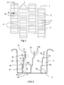
- the variant shown with the figure 5 is substantially equivalent to that shown with the figure 4 , the only difference residing in the arrangement of different sections of incision with respect to each other.
- the length H occupied by the incision 5 in the strip corresponds to the length of the perpendicular projection of each of the different thin and thick sections on the running surface 10
- this same length H was equal to the sum of said projections, that is to say to the distance separating the points Z and Z1.
- the thin sections are inclined at an angle A equal to 30 degrees with a direction perpendicular to the running surface and the thick sections are parallel to the running surface.
- outer corners 6e and internal corners 6i each of said corners being formed by a face of a section thin and one side of a thick stump.
- An outer corner 6e is intended to cooperate by contact with an inner corner 6i on an opposite face of the incision 5.
- the variant shown with this figure 5 comprises a chamfer 13 of 1 mm per 1 mm of side (that is to say making an angle equal to 45 degrees with a perpendicular to the running surface) on the trailing edge formed by the incision on the face contact in order to reduce at least in the first kilometers of rolling the wear localized on the trailing edge of the incision as defined by the present invention.
- an incision intersects the running surface along a leading edge (first to enter the contact on the same element) and a trailing edge (last out of the contact).
- the Figures 6 and 7 show the operation of the slat shown with the figure 5 during two braking maneuvers (different amplitudes of effort).
- the tire rolls on a floor S.
- the braking forces are generally greater in amplitude and lead to a contact between the walls of the thick sections: thanks to this contact it is possible to obtain even on dry ground a good performance in adhesion.
- the incision according to the invention which has been shown in blocks can be implemented in ribs. It is possible in particular to combine thin sections of different orientations in the same incision. It is also possible to combine in the same incision thick sections with different inclinations, that is to say that each section has an inclination of its own. It is also possible to combine thin and / or thick sections of different depths and of different widths. For example, an incision according to the invention may be used, the thick sections of which each have a specific thickness, the last thick section having the same thickness. largest thickness,
Description
L'invention concerne les bandes de roulement de pneu et plus particulièrement les incisions dont sont pourvues de telles bandes.The invention relates to tire treads and more particularly the incisions which are provided with such strips.
Afin d'atteindre une performance satisfaisante sur chaussée mouillée, il est connu de pourvoir une bande de roulement de pneu, ayant une surface de roulement destinée à être en contact avec la chaussée pendant le roulage, avec une pluralité de rainures d'orientation générale circonférentielle et transversale. Ces rainures présentent des largeurs supérieures à 2 mm pour des pneus de véhicules de tourisme et permettent un drainage de l'eau présente sur la chaussée par temps de pluie.In order to achieve satisfactory wet performance, it is known to provide a tire tread, having a tread surface intended to be in contact with the roadway during rolling, with a plurality of grooves of generally circumferential direction. and transverse. These grooves have widths greater than 2 mm for passenger car tires and allow drainage of the water present on the roadway during rainy weather.
Ces rainures délimitent des éléments de matière caoutchoutique sous la forme de nervures et ou de blocs, ces éléments étant délimités sur la surface de roulement par des arêtes utiles pour assurer un bon contact avec la chaussée.These grooves delimit elements of rubber material in the form of ribs and or blocks, these elements being delimited on the tread surface by edges useful to ensure good contact with the roadway.
Pour augmenter le nombre d'arêtes au contact avec la chaussée, il est connu de pourvoir les éléments de la bande de roulement avec une pluralité d'incisions, c'est-à-dire avec de fines découpures qui tout en enlevant une quantité réduite voir nulle de matière créent des faces en vis-à-vis dont les intersections avec la surface de roulement forment des arêtes. Par définition ces incisions ont des largeurs moyennes inférieures à celles des rainures (c'est-à-dire inférieure à 2 mm et le plus souvent inférieure à 1 mm). Sous les efforts exercés par le sol sur la bande de roulement, les incisions ont tendance à se fermer jusqu'à ce que les faces en vis-à-vis viennent en contact.To increase the number of ridges in contact with the roadway, it is known to provide the elements of the tread with a plurality of incisions, that is to say with fine cuts which while removing a reduced amount to see zero of material create face-to-face faces whose intersections with the rolling surface form edges. By definition, these incisions have mean widths smaller than those of the grooves (that is to say less than 2 mm and most often less than 1 mm). Under the forces exerted by the ground on the tread, the incisions tend to close until the faces facing each other come into contact.
Cette augmentation du nombre des incisions conduit dans certaines sollicitations à une diminution de la rigidité de la bande de roulement en réaction à des sollicitations exercées par la chaussée pendant le roulage.This increase in the number of incisions leads in certain stresses to a decrease in the rigidity of the tread in response to stresses exerted by the roadway during taxiing.
Afin de limiter la diminution de rigidité liée à la présence de ces fines découpures, il est connu de réaliser des faces en vis-à-vis ayant des géométries en zigzag selon une ou plusieurs directions différentes afin de générer un engrènement d'une face avec la face opposée.In order to limit the decrease in rigidity related to the presence of these fine cutouts, it is known to make face-to-face faces having zigzag geometries in one or more different directions in order to generate a meshing of a face with the opposite side.
Le document
Ces espaces formés par les tronçons perpendiculaires jouent le rôle de réservoir pour évacuer de façon temporaire l'eau éventuellement présente sur la chaussée par temps de pluie et sur laquelle passe la bande de roulement.These spaces formed by the perpendicular sections act as a reservoir to temporarily evacuate the water that may be present on the roadway in rainy weather and on which the tread passes.
Il est par ailleurs connu d'incliner selon une même orientation toutes les incisions d'une bande de roulement, ces incisions faisant un angle moyen d'inclinaison, voire des angles moyens d'inclinaison différents en valeur absolue selon la région considérée de la bande. Les incisions ont des largeurs faibles (c'est-à-dire inférieures à 2 mm) pour limiter le plus possible la diminution de rigidité, notamment en compression lorsque l'élément pourvu d'incision passe dans le contact avec la chaussée.It is also known to incline in the same orientation all the incisions of a tread, these incisions making a mean angle of inclination, or even average angles of inclination different in absolute value depending on the considered region of the band . The incisions have small widths (that is to say less than 2 mm) to minimize the decrease in rigidity, especially in compression when the element with incision passes into contact with the roadway.
Dans une telle configuration, la charge appliquée au pneu conduit à un rapprochement des parois délimitant les incisions indépendamment de tout effort moteur ou freineur exercé par la chaussée sur la bande. Ce rapprochement peut se traduire par un contact entre les faces, ce qui augmente la rigidité des éléments de la bande de roulement.In such a configuration, the load applied to the tire leads to an approximation of the walls delimiting the incisions regardless of any motor or braking force exerted by the roadway on the strip. This approximation can result in a contact between the faces, which increases the rigidity of the tread elements.
L'objectif de l'invention est de former une bande de roulement dont les éléments en relief formant la sculpture destinée à venir en contact avec la chaussée présentent un fonctionnement approprié et différencié selon l'amplitude des efforts exercés par la chaussée sur ladite bande, que ces efforts soient moteurs ou freineurs.The object of the invention is to form a tread whose relief elements forming the sculpture intended to come into contact with the roadway have an appropriate and differentiated operation according to the amplitude of the forces exerted by the roadway on said belt, that these efforts are engines or brakes.
Par effort freineur on entend un effort exercé par le sol sur la bande de roulement et orienté dans une direction opposée au sens du déplacement du pneu pourvu de ladite bande. Par effort moteur on entend un effort exercé par le sol sur la bande de roulement et orienté dans le sens du déplacement du pneu pourvu de ladite bande.By braking effort is meant a force exerted by the ground on the tread and oriented in a direction opposite to the direction of movement of the tire provided with said band. By motor force is meant a force exerted by the ground on the tread and oriented in the direction of movement of the tire provided with said strip.
Il est proposé une bande de roulement pour pneu de véhicule tourisme, cette bande de roulement ayant radialement à l'extérieur une surface de roulement destinée à venir en contact avec la chaussée pendant le roulage et comprenant une pluralité d'éléments délimités par des découpures (ces éléments peuvent être des nervures ou des blocs). Au moins certains de ces éléments sont pourvus d'au moins une incision délimitée par deux faces en vis-à-vis, cette incision étant composée par une succession de tronçons minces et de tronçons épais disposés de manière alternée (un tronçon mince est suivi par un tronçon épais).A tread for a passenger car tire is proposed, this tread having radially outwardly a tread surface intended to come into contact with the roadway during driving and comprising a plurality of elements delimited by cutouts ( these elements may be ribs or blocks). At least some of these elements are provided with at least one incision delimited by two faces facing each other, this incision being composed of a succession of thin sections and of thick sections arranged alternately (a thin section is followed by a thick section).
La bande selon l'invention est telle que chaque tronçon mince est incliné d'un angle moyen A au plus égal à 40 degrés, cet angle étant mesuré par rapport à une direction perpendiculaire à la surface de roulement de la bande et passant par les points de l'incision sur la surface de roulement de la bande, et chaque tronçon épais fait un angle moyen B compris entre 60 degrés et 120 degrés avec une direction perpendiculaire à la surface de roulement de la bande. En outre les tronçons minces ont une largeur moyenne inférieure à la largeur moyenne des tronçons épais, la largeur des tronçons minces étant telle qu'au passage dans le contact les parois délimitant lesdits tronçons minces sont en contact, la largeur des tronçons épais étant telle qu'au passage dans le contact les parois délimitant les tronçons épais ne sont pas en contact.The strip according to the invention is such that each thin section is inclined by an average angle A at most equal to 40 degrees, this angle being measured relative to a direction perpendicular to the running surface of the strip and passing through the points. of the incision on the running surface of the strip, and each thick section makes an average angle B between 60 degrees and 120 degrees with a direction perpendicular to the running surface of the strip. In addition, the thin sections have an average width that is smaller than the average width of the thick sections, the width of the thin sections being such that, when passing through the contact, the walls delimiting said thin sections are in contact, the width of the thick sections being such that when passing through the contact the walls delimiting the thick sections are not in contact.
Pour que cette solution soit pleinement efficace, il est préférable que les tronçons minces soient fermés au moment du passage dans le contact avec la chaussée. Par fermé, on entend que les parois, délimitant un tronçon mince, sont en contact l'une sur l'autre quasiment sous la simple action de la charge supportée. Grâce à l'alternance de tronçons minces et de tronçons épais, ces derniers étant orientés de façon à être sensiblement parallèles à la surface de roulement (c'est-à-dire perpendiculaires à un plan passant par l'axe de rotation et les points de l'incision les plus à l'intérieur de la bande), on peut créer un effet de seuil. Par effet de seuil, on entend ici que jusqu'à un seuil d'amplitude d'effort tangentiel de la chaussée sur la bande de roulement, les parois en vis-à-vis de l'incision sont en contact sur les tronçons minces et restent fixes l'une par rapport à l'autre : tout se passe comme si la rigidité de l'élément était équivalente à celle du même élément sans incision. Au delà de ce seuil d'amplitude d'effort tangentiel, les parois en contact peuvent glisser l'une par rapport à l'autre à la fois parce que les forces de frottement sont vaincues et parce qu'il y a une possibilité de déplacement relatif liée à la présence de tronçons épais.For this solution to be fully effective, it is preferable that the thin sections are closed when passing into contact with the roadway. Closed means that the walls delimiting a thin section, are in contact with one another almost under the simple action of the load supported. Thanks to the alternation of thin sections and thick sections, the latter being oriented so as to be substantially parallel to the running surface (that is to say perpendicular to a plane passing through the axis of rotation and the points most incision inside the band), we can create a threshold effect. By threshold effect, it is meant here that up to a threshold of amplitude of tangential force of the roadway on the tread, the walls opposite the incision are in contact on the thin sections and remain fixed in relation to each other: everything happens as if the rigidity of the element was equivalent to that of the same element without incision. Beyond this threshold of amplitude of tangential effort, the walls in contact can slide relative to each other at a time because the friction forces are overcome and because there is a possibility of displacement relative to the presence of thick sections.
Préférentiellement les tronçons minces d'incision ont une largeur au plus égale à 0.4 mm et les tronçons épais d'incision ont une largeur plus grande que 0.4 mm, l'écart entre les largeurs des tronçons minces et des tronçons épais étant au moins égal à 0.2 mm.Preferably, the thin sections of incision have a width at most equal to 0.4 mm and the thick sections of incision have a width greater than 0.4 mm, the difference between the widths of the thin sections and the thick sections being at least equal to 0.2 mm.
Encore plus avantageusement, les tronçons minces d'incision ont une largeur au plus égale à 0.15 mm et les tronçons épais d'incision ont une largeur plus grande que 0.4 mm.Even more advantageously, the thin sections of incision have a width at most equal to 0.15 mm and the thick sections of incision have a width greater than 0.4 mm.
La présente incision se différencie des incisions de l'art antérieur puisque ces dernières ne présentaient pas de différentiation du comportement mécanique en fonction de l'amplitude de l'effort exercé par la chaussée sur la bande de roulement, que cet effort soit un effort moteur ou un effort freineur.The present incision differs from the incisions of the prior art since the latter did not have any differentiation of the mechanical behavior as a function of the amplitude of the force exerted by the roadway on the tread, that this effort is a driving force or a braking effort.
Grâce aux différences de largeurs entre les tronçons minces et les tronçons épais et à leurs orientations telles que spécifiées, on améliore la performance en manoeuvre de freinage de la bande. Il est ainsi possible d'adapter la rigidité de chaque élément pourvu d'incisions telles que décrites puisque à faibles efforts freineurs (efforts exercés par la chaussée sur la bande et tendant à s'opposer au déplacement) les forces de frottement des parois en contact sont suffisants pour maintenir bloquées lesdites parois, tandis qu'à plus forts efforts freineurs les forces de frottement des parois en contact l'une sur l'autre sont insuffisantes pour résister au glissement d'une paroi par rapport à l'autre. Dans ce dernier cas, il se produit un glissement qui est possible et toutefois limité en amplitude par la largeur des tronçons d'incision épais. Ce comportement différencié en fonction de l'amplitude de l'effort freineur est particulièrement intéressant puisque des faibles efforts freineurs ou moteurs sont notamment ceux qui interviennent dans les mécanismes d'usure tandis que les efforts freineurs plus élevés interviennent dans des roulages en conditions sur chaussée mouillée. Dans ce dernier cas (forts efforts freineurs), on cherche à ce que l'élément de matière puisse se déformer davantage pour améliorer la performance de freinage sur chaussée revêtue d'eau.Thanks to the differences in widths between the thin sections and the thick sections and their orientations as specified, the performance in braking maneuver of the strip is improved. It is thus possible to adapt the rigidity of each element provided with incisions as described since low braking efforts (forces exerted by the roadway on the belt and tending to oppose the displacement) the friction forces of the walls in contact are sufficient to keep said walls locked, while at higher braking efforts the frictional forces of the walls in contact with one another are insufficient to resist slippage of one wall relative to the other. In the latter case, there is a slip which is possible and however limited in amplitude by the width of the thick incision sections. This differentiated behavior as a function of the amplitude of the braking force is particularly interesting since low braking or motor forces are in particular those involved in the wear mechanisms while the higher braking forces are involved in driving under conditions on the road. wet. In the latter case (strong braking efforts), it is sought that the element of material can be further deformed to improve the braking performance on pavement coated with water.
Dans une variante particulièrement intéressante de l'invention, il est proposé d'orienter les incisions de manière à ce que, lorsque la bande de roulement est soumise à un effort moyen moteur exercé par la chaussée, les tronçons minces des incisions aient tendance à rester fermement en contact, ce qui est avantageux pour réduire l'usure sous effort moteur.In a particularly advantageous variant of the invention, it is proposed to orient the incisions so that, when the tread is subjected to an average driving force exerted by the roadway, the thin sections of the incisions tend to remain firmly in contact, which is advantageous for reducing wear under engine force.
Dans ce but, il est proposée une bande de roulement qui comporte un indicateur du sens de roulement imposé, cette bande de roulement ayant au moins une incision comprenant au moins un tronçon mince et un tronçon épais, les tronçons minces étant inclinés de façon que, vue en coupe dans un plan perpendiculaire à l'axe de rotation du pneu, la direction de l'indicateur de sens de roulement imposé soit identique au sens de rotation dont il faut faire tourner ledit tronçon d'incision, autour de son point le plus à l'intérieur de la bande, pour amener ce tronçon dans un plan contenant l'axe de rotation, chaque tronçon mince étant incliné d'un angle moyen A au moins égal à 20 degrés et au plus égal à 40 degrés avec une direction perpendiculaire à la surface de roulement.For this purpose, it is proposed a tread which includes an indicator of the imposed rolling direction, this tread having at least one incision comprising at least one thin section and a thick section, the thin sections being inclined so that, sectional view in a plane perpendicular to the axis of rotation of the tire, the direction of the imposed direction of rotation indicator is identical to the direction of rotation of which it is necessary to rotate said incision section, around its most within the strip, for bringing this section into a plane containing the axis of rotation, each thin section being inclined by a mean angle A of at least 20 degrees and at most equal to 40 degrees with a perpendicular direction to the running surface.
Ainsi, on bénéficie d'un effet de seuil en fonction de l'amplitude de l'effort freineur exercée par le sol sur la bande et en outre l'orientation choisie en combinaison avec la direction d'avancement du pneu pourvu de ladite bande permet d'optimiser le fonctionnement de cette bande de roulement notamment sous effort moteur.Thus, there is a threshold effect as a function of the amplitude of the braking force exerted by the ground on the belt and furthermore the orientation chosen in combination with the direction of advance of the tire provided with said belt allows to optimize the operation of this tread especially under engine force.
D'autres caractéristiques et avantages de l'invention ressortent de la description faite ci-après en référence aux dessins annexés qui montrent, à titre d'exemples non limitatifs, des formes de réalisation de l'objet de l'invention.Other features and advantages of the invention emerge from the description given hereinafter with reference to the accompanying drawings which show, by way of non-limiting examples, embodiments of the subject of the invention.
La
La
Les
Toutes les figures accompagnant la présente description sont données à titre indicatif et les dimensions qu'elles soient absolues ou relatives ne sont qu'indicatives ; par ailleurs, un même élément de structure sera repéré par la même référence numérique sur des figures montrant des variantes différentes de l'invention.All the figures accompanying this description are given for information only and the dimensions, whether absolute or relative, are only indicative; moreover, the same structural element will be identified by the same numerical reference in figures showing different variants of the invention.
Une bande de roulement pour pneu est limitée par des surfaces externes dont une a pour vocation à être en contact avec une structure de pneu et une autre est destinée à être en contact avec la chaussée en cours d'utilisation ; la direction sensiblement perpendiculaire à ces deux surfaces est dite direction radiale sur le pneu. Suivant cette direction on mesure l'épaisseur de la bande.A tire tread is limited by external surfaces, one of which is intended to be in contact with a tire structure and another is intended to be in contact with the roadway in use; the direction substantially perpendicular to these two surfaces is said radial direction on the tire. In this direction, the thickness of the strip is measured.
La
Sur la
Les tronçons minces 51 sont délimités par des parois 510 en vis-à-vis et ont une largeur e inférieure à la largeur E des tronçons épais 52 ; la largeur e des tronçons minces est telle qu'au passage dans le contact les parois 510 délimitant lesdits tronçons minces sont quasiment instantanément en contact (ces mêmes parois 510 peuvent être en contact avant même de passer dans le contact dans le cas notamment d'incision de largeur nulle). Dans le cas présent l'épaisseur e, mesurée perpendiculairement aux parois délimitant l'incision sur le tronçon mince considéré, vaut 0.3 mm. La largeur E des tronçons épais 52, mesurée perpendiculairement aux parois délimitant l'incision sur le tronçon épais considéré, est supérieure à celle des tronçons minces 51 et telle que sous l'action seule de la charge supportée, les parois 520 délimitant les tronçons épais 52 ne sont pas en contact. La largeur E vaut dans le cas présent 0.8 mm.The
La longueur P des tronçons épais est un paramètre de réglage à la disposition de la personne du métier pour régler l'encombrement de l'incision et également pour assurer un bon blocage lors de certaines manoeuvres. Le point Z1 le plus à l'intérieur de l'incision 5 est ici formé par un élargissement 53 utile pour réduire les concentrations de contrainte. Les tronçons épais génèrent des coins 6i et 6e de matière qui peuvent venir en contact lors d'un déplacement relatif des faces délimitant les tronçons minces. Les coins de matière 6e sont situés du côté de la face de contact par rapport aux coins 6i. Ce point Z1 a pour projection sur la face de contact de l'élément un point Z dans le plan de coupe de la
Lors d'une manoeuvre produisant un effort tangentiel de la chaussée sur la bande de roulement, et en fonction de l'amplitude de cet effort, on obtient grâce à cette incision un fonctionnement mécanique variable selon que l'effort F est inférieur à un seuil prédéterminé d'effort Fs ou supérieur à ce seuil Fs. En effet, pour des efforts compris entre zéro et la valeur de seuil Fs, les forces de frottement résultant des contacts entre les parois 510 des tronçons minces 51 sont suffisantes pour s'opposer au déplacement relatif desdites parois. Pour des efforts F supérieurs à la valeur de seuil, les parois des tronçons minces en contact vont glisser l'une par rapport à l'autre favorisant ainsi une plus grande déformation des éléments de la bande de roulement et par là un meilleur contact avec la chaussée. Ce glissement se fait jusqu'à ce que les parois des tronçons épais viennent en contact les unes sur les autres assurant dès lors un blocage des mouvements relatifs et donc de la déformation de la bande. Ainsi il est possible de gérer le fonctionnement mécanique de chaque élément de relief de la bande en réglant a priori la valeur du seuil Fs en fonction de l'amplitude de l'effort considéré (moteur ou freineur) qui s'exerce sur une bande de roulement notamment en considérant le véhicule et les conditions de roulage.During a maneuver producing a tangential force of the roadway on the tread, and depending on the amplitude of this effort, this incision results in a variable mechanical operation according to the fact that the force F is below a threshold predetermined force Fs or greater than this threshold Fs. Indeed, for forces between zero and the threshold value Fs, the friction forces resulting from the contacts between the
Selon que l'on est dans une configuration d'effort moteur ou dans une configuration d'effort freineur, on peut obtenir des seuils d'effort de valeurs différentes : sous effort moteur le seuil au-delà duquel il y a glissement des parois opposées des parties minces peut être plus grand que le seuil sous effort freineur pour avoir glissement.Depending on whether one is in a motor force configuration or in a braking force configuration, it is possible to obtain force thresholds of different values: under engine force the threshold beyond which the opposing walls slide thin parts may be larger than the threshold under braking force to have slip.
Comme on l'a constaté, chacun de ces seuils dépend de la limite à partir de laquelle il se produit un glissement des parois des tronçons minces les unes sur les autres. Cette limite et donc ces seuils d'effort Fs peuvent être ajustés grâce à différents facteurs à la disposition de la personne du métier et notamment :As we have seen, each of these thresholds depends on the limit from which there is a sliding of the walls of the thin sections on each other. This limit and therefore these effort thresholds Fs can be adjusted thanks to various factors at the disposal of the person skilled in the art and in particular:
- les dimensions des parois en contact ;- the dimensions of the walls in contact;
- les coefficients de frottement de contact des parois entre elles ;the friction coefficients of contact of the walls with each other;
- l'épaisseur e de l'incision dans le tronçon mince (plus cette épaisseur est réduite et plus le seuil Fs est décalé vers des valeurs plus grandes).- The thickness e of the incision in the thin section (the smaller this thickness is reduced and the threshold Fs is shifted to larger values).
Au delà du seuil Fs, les parois 510 des tronçons minces peuvent donc glisser les unes sur les autres ; la limite de l'amplitude de ce glissement est sensiblement égale à la largeur E des tronçons épais 52 ; cette largeur E est mesurée parallèlement à la direction des tronçons minces (dans le cas présent dans une direction perpendiculaire à la surface de roulement). Cette largeur E est également un paramètre de réglage à la disposition de la personne du métier pour limiter l'amplitude du glissement.Beyond the threshold Fs, the
La variante d'incision 5, montrée en coupe à la
Dans la variante montrée avec la
La variante montrée avec la
En outre, la variante montrée avec cette
Les
Sous l'action de la charge portée par le pneu, on obtient une fermeture de l'incision par la mise en contact des parois 510 des tronçons minces 51. Dans une première manoeuvre de freinage, représentée avec la
Dans une deuxième manoeuvre de freinage - montrée avec la
On voit que dans cette deuxième manoeuvre de freinage les coins externes 6e se sont rapprochés des coins internes 6i. Si l'effort freineur augmente, ces coins externes et internes viennent en contact pour limiter alors la déformation de l'élément 2 de bande de roulement.We see that in this second braking maneuver the outer corners 6e are closer to the
Dans cette manoeuvre de freinage imposant un effort de freinage supérieur au seuil Fs, on constate que grâce aux glissements des parois des tronçons minces de l'incision 5, on obtient une sorte de soulèvement local des parties d'attaque 11, 12 du bloc 10. Une desdites parties d'attaque correspond à l'arête d'attaque du bloc et l'autre correspond à l'une des arêtes formées par l'incision 5 dans le bloc. Grâce à ces soulèvements locaux, la pression moyenne de contact du bloc avec la chaussée augmente, ce qui a pour conséquence une amélioration de l'adhérence sur sol revêtu d'eau.In this braking maneuver imposing a braking force greater than the threshold Fs, it can be seen that, thanks to the sliding of the walls of the thin sections of the
Sur sol sec, les efforts de freinage sont en général plus importants en amplitude et conduisent à une mise en contact des parois des tronçons épais : grâce à ce contact il est possible d'obtenir même sur sol sec une bonne performance en adhérence.On dry ground, the braking forces are generally greater in amplitude and lead to a contact between the walls of the thick sections: thanks to this contact it is possible to obtain even on dry ground a good performance in adhesion.
A l'inverse de l'effort freineur, l'application d'un effort moteur tend à accentuer la fermeture des incisions sur les tronçons minces par une augmentation sensible de la pression de contact qu'exerce une paroi sur la paroi en vis-à-vis sur ces mêmes tronçons minces. Ceci permet d'éviter le glissement relatif entre les parois des incisions minces et en conséquence confère à la sculpture une rigidité élevée sous effort moteur (c'est-à-dire une sculpture proche d'une sculpture sans incision), gage d'une bonne performance en usure.Contrary to the braking force, the application of a motor force tends to accentuate the closing of the incisions on the thin sections by a significant increase in the contact pressure exerted by a wall on the wall opposite. -vis on these same thin sections. This avoids the relative sliding between the walls of the thin incisions and consequently gives the sculpture a high rigidity under motor force (that is to say a sculpture close to a sculpture without incision), a pledge of good performance in wear.
L'invention n'est pas limitée aux exemples décrits et représentés et diverses modifications peuvent y être apportées sans sortir de son cadre. L'incision selon l'invention qui a été montrée dans des blocs peut être mise en oeuvre dans des nervures. Il est possible notamment de combiner des tronçons minces d'orientations différentes dans une même incision. Il est également possible de combiner dans une même incision des tronçons épais ayant des inclinaisons différentes, c'est-à-dire que chaque tronçon a une inclinaison qui lui est propre. Il est également possible de combiner des tronçons minces et/ou épais de profondeurs différentes et de largeur différentes, Par exemple, on peut employer une incision selon l'invention dont les tronçons épais ont chacun une épaisseur propre, le dernier tronçon épais ayant l'épaisseur la plus grande,The invention is not limited to the examples described and shown and various modifications can be made without departing from its scope. The incision according to the invention which has been shown in blocks can be implemented in ribs. It is possible in particular to combine thin sections of different orientations in the same incision. It is also possible to combine in the same incision thick sections with different inclinations, that is to say that each section has an inclination of its own. It is also possible to combine thin and / or thick sections of different depths and of different widths. For example, an incision according to the invention may be used, the thick sections of which each have a specific thickness, the last thick section having the same thickness. largest thickness,
Claims (5)
- Tread (1) for a passenger-vehicle tyre, this tread having radially on the outside a running surface (10) designed to come into contact with the road surface when running, this tread comprising a plurality of elements (2) delimited by indentations, at least certain of these elements being provided with at least one incision (5) delimited by two opposite faces, this incision consisting of a succession of thin sections (51) and of thick sections (52) placed in an alternating manner, this tread being characterized in that each thin section (51) is inclined at an average angle A equal to no more than 40 degrees, this angle being measured relative to a direction perpendicular to the running surface of the tread and passing through the points of the incision on the running surface of the tread, each thick section (52) makes an average angle B of between 60 degrees and 120 degrees with a direction perpendicular to the running surface of the tread, and in that the thin sections (51) have a width e less than the width E of the thick sections (52), the width of the thin sections being such that, when they go through the contact patch, the walls delimiting the said thin sections are in contact, and the width of the thick sections being such that, when they go through the contact patch, the walls delimiting the thick sections are not in contact.
- Tread according to Claim 1, characterized in that the thin sections (51) of incision have a width equal to no more than 0.4 mm and in that the thick sections (52) of incision have a width of more than 0.4 mm, the difference between the widths of the thin sections (51) and of the thick sections (52) being at least equal to 0.2 mm.
- Tread according to Claim 2, characterized in that the thin sections (51) of incision have a width equal to no more than 0.15 mm and in that the thick sections (52) of incision have a width of more than 0.4 mm.
- Tread according to one of Claims 1 to 3, characterized in that it has an imposed running direction and in that it comprises an indicator of this running direction, and in that at least one incision comprises at least one thin section (51) and one thick section (52), the thin sections (51) being inclined so that, seen in section in a plane perpendicular to the rotation axis of the tyre, the direction of the indicator of the imposed running direction is identical to the rotation direction in which the said thin section (51) of incision must be made to rotate about its innermost point of the tread in order to bring this thin section (51) into a plane containing the rotation axis, the thin sections (51) being inclined at an angle A at least equal to 20 degrees and equal to no more than 40 degrees with a direction perpendicular to the running surface (10).
- Tread according to one of Claims 1 to 4, characterized in that each incision (5) cutting the running surface (10) in order to form a leading edge and a trailing edge, the trailing edge comprises a bevel (13).
Applications Claiming Priority (2)
| Application Number | Priority Date | Filing Date | Title |
|---|---|---|---|
| FR0858295A FR2939360B1 (en) | 2008-12-05 | 2008-12-05 | BEARING BAND WITH INCISIONS |
| PCT/EP2009/066214 WO2010063751A1 (en) | 2008-12-05 | 2009-12-02 | Tread with incisions |
Publications (2)
| Publication Number | Publication Date |
|---|---|
| EP2373503A1 EP2373503A1 (en) | 2011-10-12 |
| EP2373503B1 true EP2373503B1 (en) | 2012-10-31 |
Family
ID=40639424
Family Applications (1)
| Application Number | Title | Priority Date | Filing Date |
|---|---|---|---|
| EP09760910A Active EP2373503B1 (en) | 2008-12-05 | 2009-12-02 | Tread with incisions |
Country Status (8)
| Country | Link |
|---|---|
| US (1) | US9211767B2 (en) |
| EP (1) | EP2373503B1 (en) |
| JP (1) | JP5583684B2 (en) |
| CN (1) | CN102227324B (en) |
| BR (1) | BRPI0922142A2 (en) |
| EA (1) | EA018685B1 (en) |
| FR (1) | FR2939360B1 (en) |
| WO (1) | WO2010063751A1 (en) |
Families Citing this family (18)
| Publication number | Priority date | Publication date | Assignee | Title |
|---|---|---|---|---|
| EP2913205B1 (en) * | 2012-10-24 | 2018-06-06 | Bridgestone Corporation | Pneumatic tire |
| WO2014099471A1 (en) * | 2012-12-19 | 2014-06-26 | Bridgestone Americas Tire Operations, Llc | Tire with bi-directional performance |
| JP6317356B2 (en) * | 2013-08-28 | 2018-04-25 | 株式会社ブリヂストン | Heavy duty pneumatic tire |
| WO2017141912A1 (en) * | 2016-02-15 | 2017-08-24 | 横浜ゴム株式会社 | Pneumatic tire |
| EP3490816B1 (en) * | 2016-07-27 | 2022-03-09 | Bridgestone Americas Tire Operations, LLC | Three-dimensional tire sipe |
| JP6759930B2 (en) * | 2016-09-26 | 2020-09-23 | 横浜ゴム株式会社 | Pneumatic tires |
| JP6828496B2 (en) * | 2017-02-17 | 2021-02-10 | 横浜ゴム株式会社 | Pneumatic tires |
| JP6828495B2 (en) * | 2017-02-17 | 2021-02-10 | 横浜ゴム株式会社 | Pneumatic tires |
| JP6929107B2 (en) * | 2017-04-10 | 2021-09-01 | 株式会社ブリヂストン | Pneumatic radial tires for heavy loads |
| CN110785293B (en) * | 2017-06-19 | 2021-12-03 | 株式会社普利司通 | Tyre for vehicle wheels |
| WO2019027423A1 (en) * | 2017-07-31 | 2019-02-07 | Compagnie Generale Des Etablissements Michelin | Tire tread having tread blocks with inclined trailing side and sipe |
| DE102017213820A1 (en) * | 2017-08-08 | 2019-02-14 | Continental Reifen Deutschland Gmbh | Vehicle tires |
| EP3527407B1 (en) * | 2018-02-15 | 2022-05-04 | Nokian Renkaat Oyj | A tread block arrangement having a supporting sipe |
| JP7152361B2 (en) * | 2019-06-14 | 2022-10-12 | 株式会社ブリヂストン | pneumatic tire |
| US20240042803A1 (en) | 2020-12-18 | 2024-02-08 | Bridgestone Europe NV/SA [BE/BE] | Tyre tread with improved sipe on three levels and tyre |
| KR102612469B1 (en) * | 2021-08-20 | 2023-12-12 | 한국타이어앤테크놀로지 주식회사 | Kerf structure with improved tread block stiffness |
| WO2023064704A1 (en) * | 2021-10-16 | 2023-04-20 | Bridgestone Americas Tire Operations, Llc | Directional interlocking sipe and/or slot |
| WO2023064703A1 (en) * | 2021-10-16 | 2023-04-20 | Bridgestone Americas Tire Operations, Llc | Directional interlocking sipe and/or slot with chamfer |
Family Cites Families (11)
| Publication number | Priority date | Publication date | Assignee | Title |
|---|---|---|---|---|
| FR2612129B1 (en) * | 1987-03-10 | 1989-09-29 | Michelin & Cie | TREAD FOR RADIAL TIRES OF WHICH THE RELATED ELEMENTS ARE INCORPORATED WITH BROKEN OR CORRUGATED LINE TRACKS IN THE SENSE OF THEIR DEPTHS |
| FR2703002B1 (en) * | 1993-03-25 | 1995-06-02 | Michelin & Cie | Tread for radial tire having elements in relief provided with incisions. |
| DE19650701A1 (en) * | 1996-12-06 | 1998-06-10 | Continental Ag | Pneumatic vehicle tires |
| JPH11151915A (en) * | 1997-11-21 | 1999-06-08 | Bridgestone Corp | Pneumatic tire |
| DE60116190T2 (en) | 2000-07-03 | 2006-08-17 | Société de Technologie Michelin | Pneumatic tire with a tread for heavy loads |
| JP4711373B2 (en) * | 2001-04-24 | 2011-06-29 | 東洋ゴム工業株式会社 | Pneumatic tire |
| DE60209956T2 (en) * | 2001-05-14 | 2006-11-30 | Société de Technologie Michelin | Tread with inclination variable sipes containing ribs |
| JP4330455B2 (en) * | 2004-01-09 | 2009-09-16 | 住友ゴム工業株式会社 | Pneumatic tire |
| JP4294507B2 (en) * | 2004-02-05 | 2009-07-15 | 株式会社ブリヂストン | Pneumatic tire |
| US20090000713A1 (en) * | 2007-06-27 | 2009-01-01 | Bridgestone Firestone North American Tire, Llc | Tire including segmented sipes |
| DE102008030810A1 (en) * | 2008-06-28 | 2009-12-31 | Continental Aktiengesellschaft | Vehicle tires |
-
2008
- 2008-12-05 FR FR0858295A patent/FR2939360B1/en not_active Expired - Fee Related
-
2009
- 2009-12-02 EP EP09760910A patent/EP2373503B1/en active Active
- 2009-12-02 WO PCT/EP2009/066214 patent/WO2010063751A1/en active Application Filing
- 2009-12-02 JP JP2011539013A patent/JP5583684B2/en not_active Expired - Fee Related
- 2009-12-02 EA EA201170760A patent/EA018685B1/en not_active IP Right Cessation
- 2009-12-02 BR BRPI0922142A patent/BRPI0922142A2/en not_active IP Right Cessation
- 2009-12-02 US US13/132,909 patent/US9211767B2/en not_active Expired - Fee Related
- 2009-12-02 CN CN2009801479608A patent/CN102227324B/en not_active Expired - Fee Related
Also Published As
| Publication number | Publication date |
|---|---|
| JP5583684B2 (en) | 2014-09-03 |
| CN102227324B (en) | 2013-11-06 |
| FR2939360A1 (en) | 2010-06-11 |
| US9211767B2 (en) | 2015-12-15 |
| FR2939360B1 (en) | 2011-03-04 |
| WO2010063751A1 (en) | 2010-06-10 |
| BRPI0922142A2 (en) | 2016-01-05 |
| EA201170760A1 (en) | 2011-12-30 |
| EA018685B1 (en) | 2013-09-30 |
| EP2373503A1 (en) | 2011-10-12 |
| US20120132337A1 (en) | 2012-05-31 |
| JP2012510921A (en) | 2012-05-17 |
| CN102227324A (en) | 2011-10-26 |
Similar Documents
| Publication | Publication Date | Title |
|---|---|---|
| EP2373503B1 (en) | Tread with incisions | |
| EP2373502B1 (en) | Tire tread comprising incisions provided with projections | |
| CA2428572C (en) | Pneumatic tire tread | |
| EP1170153B1 (en) | Tread for pneumatic tire carrying heavy loads | |
| EP2588327B1 (en) | Tread, the rolling noise of which is reduced | |
| EP2013037B1 (en) | Running tread incision comprising blocking parts | |
| EP1506099B1 (en) | Wear-adaptable running tread | |
| EP2563604B1 (en) | Tread for a tire for a trailer-type heavy vehicle | |
| EP2318219B1 (en) | Tyre tread with directional pattern | |
| FR2933335A1 (en) | DIRECTIONAL TIRE BAND FOR TIRES WITH ADAPTED INCISIONS | |
| CH628293A5 (en) | TIRE FOR RIDING ON SNOW. | |
| EP2925542A1 (en) | Snow tyre tread comprising incisions and cavities | |
| EP3802154B1 (en) | Tyre tread comprising wavy grooves and sipes | |
| EP2661376B1 (en) | Tire for heavy duty vehicle and arrangement of tires of a drive axle and a steering axle | |
| EP3325284A1 (en) | Heavy vehicle tyre tread with improvement to running noise | |
| FR2954221A1 (en) | TIRE WITH IMPROVED RUNNING PERFORMANCE | |
| EP1283115B1 (en) | Surface profile of tread elements for tyre | |
| EP2373500B1 (en) | Tire tread comprising incisions and recesses | |
| EP3658390B1 (en) | Tyre with tread comprising an evolving tread pattern with sipes | |
| EP3681737B1 (en) | Mould for a tyre tread comprising concealed channels | |
| FR2953453A1 (en) | TIRE TREAD FOR TIRES | |
| FR2953454A1 (en) | TIRE TREAD FOR TIRES |
Legal Events
| Date | Code | Title | Description |
|---|---|---|---|
| PUAI | Public reference made under article 153(3) epc to a published international application that has entered the european phase |
Free format text: ORIGINAL CODE: 0009012 |
|
| 17P | Request for examination filed |
Effective date: 20110705 |
|
| AK | Designated contracting states |
Kind code of ref document: A1 Designated state(s): AT BE BG CH CY CZ DE DK EE ES FI FR GB GR HR HU IE IS IT LI LT LU LV MC MK MT NL NO PL PT RO SE SI SK SM TR |
|
| DAX | Request for extension of the european patent (deleted) | ||
| GRAP | Despatch of communication of intention to grant a patent |
Free format text: ORIGINAL CODE: EPIDOSNIGR1 |
|
| RAP1 | Party data changed (applicant data changed or rights of an application transferred) |
Owner name: MICHELIN RECHERCHE ET TECHNIQUE S.A. Owner name: COMPAGNIE GENERALE DES ETABLISSEMENTS MICHELIN |
|
| GRAS | Grant fee paid |
Free format text: ORIGINAL CODE: EPIDOSNIGR3 |
|
| GRAA | (expected) grant |
Free format text: ORIGINAL CODE: 0009210 |
|
| AK | Designated contracting states |
Kind code of ref document: B1 Designated state(s): AT BE BG CH CY CZ DE DK EE ES FI FR GB GR HR HU IE IS IT LI LT LU LV MC MK MT NL NO PL PT RO SE SI SK SM TR |
|
| REG | Reference to a national code |
Ref country code: GB Ref legal event code: FG4D Free format text: NOT ENGLISH Ref country code: CH Ref legal event code: EP |
|
| REG | Reference to a national code |
Ref country code: AT Ref legal event code: REF Ref document number: 581784 Country of ref document: AT Kind code of ref document: T Effective date: 20121115 |
|
| REG | Reference to a national code |
Ref country code: IE Ref legal event code: FG4D Free format text: LANGUAGE OF EP DOCUMENT: FRENCH |
|
| REG | Reference to a national code |
Ref country code: DE Ref legal event code: R096 Ref document number: 602009010873 Country of ref document: DE Effective date: 20121227 |
|
| REG | Reference to a national code |
Ref country code: AT Ref legal event code: MK05 Ref document number: 581784 Country of ref document: AT Kind code of ref document: T Effective date: 20121031 |
|
| REG | Reference to a national code |
Ref country code: LT Ref legal event code: MG4D |
|
| REG | Reference to a national code |
Ref country code: NL Ref legal event code: VDEP Effective date: 20121031 |
|
| PG25 | Lapsed in a contracting state [announced via postgrant information from national office to epo] |
Ref country code: HR Free format text: LAPSE BECAUSE OF FAILURE TO SUBMIT A TRANSLATION OF THE DESCRIPTION OR TO PAY THE FEE WITHIN THE PRESCRIBED TIME-LIMIT Effective date: 20121031 Ref country code: NO Free format text: LAPSE BECAUSE OF FAILURE TO SUBMIT A TRANSLATION OF THE DESCRIPTION OR TO PAY THE FEE WITHIN THE PRESCRIBED TIME-LIMIT Effective date: 20130131 Ref country code: IS Free format text: LAPSE BECAUSE OF FAILURE TO SUBMIT A TRANSLATION OF THE DESCRIPTION OR TO PAY THE FEE WITHIN THE PRESCRIBED TIME-LIMIT Effective date: 20130228 Ref country code: SE Free format text: LAPSE BECAUSE OF FAILURE TO SUBMIT A TRANSLATION OF THE DESCRIPTION OR TO PAY THE FEE WITHIN THE PRESCRIBED TIME-LIMIT Effective date: 20121031 Ref country code: FI Free format text: LAPSE BECAUSE OF FAILURE TO SUBMIT A TRANSLATION OF THE DESCRIPTION OR TO PAY THE FEE WITHIN THE PRESCRIBED TIME-LIMIT Effective date: 20121031 Ref country code: NL Free format text: LAPSE BECAUSE OF FAILURE TO SUBMIT A TRANSLATION OF THE DESCRIPTION OR TO PAY THE FEE WITHIN THE PRESCRIBED TIME-LIMIT Effective date: 20121031 Ref country code: LT Free format text: LAPSE BECAUSE OF FAILURE TO SUBMIT A TRANSLATION OF THE DESCRIPTION OR TO PAY THE FEE WITHIN THE PRESCRIBED TIME-LIMIT Effective date: 20121031 |
|
| PG25 | Lapsed in a contracting state [announced via postgrant information from national office to epo] |
Ref country code: PT Free format text: LAPSE BECAUSE OF FAILURE TO SUBMIT A TRANSLATION OF THE DESCRIPTION OR TO PAY THE FEE WITHIN THE PRESCRIBED TIME-LIMIT Effective date: 20130228 Ref country code: SI Free format text: LAPSE BECAUSE OF FAILURE TO SUBMIT A TRANSLATION OF THE DESCRIPTION OR TO PAY THE FEE WITHIN THE PRESCRIBED TIME-LIMIT Effective date: 20121031 Ref country code: PL Free format text: LAPSE BECAUSE OF FAILURE TO SUBMIT A TRANSLATION OF THE DESCRIPTION OR TO PAY THE FEE WITHIN THE PRESCRIBED TIME-LIMIT Effective date: 20121031 Ref country code: LV Free format text: LAPSE BECAUSE OF FAILURE TO SUBMIT A TRANSLATION OF THE DESCRIPTION OR TO PAY THE FEE WITHIN THE PRESCRIBED TIME-LIMIT Effective date: 20121031 Ref country code: GR Free format text: LAPSE BECAUSE OF FAILURE TO SUBMIT A TRANSLATION OF THE DESCRIPTION OR TO PAY THE FEE WITHIN THE PRESCRIBED TIME-LIMIT Effective date: 20130201 |
|
| PG25 | Lapsed in a contracting state [announced via postgrant information from national office to epo] |
Ref country code: AT Free format text: LAPSE BECAUSE OF FAILURE TO SUBMIT A TRANSLATION OF THE DESCRIPTION OR TO PAY THE FEE WITHIN THE PRESCRIBED TIME-LIMIT Effective date: 20121031 |
|
| BERE | Be: lapsed |
Owner name: MICHELIN RECHERCHE ET TECHNIQUE S.A. Effective date: 20121231 Owner name: CIE GENERALE DES ETABLISSEMENTS MICHELIN Effective date: 20121231 |
|
| PG25 | Lapsed in a contracting state [announced via postgrant information from national office to epo] |
Ref country code: MC Free format text: LAPSE BECAUSE OF NON-PAYMENT OF DUE FEES Effective date: 20121231 Ref country code: DK Free format text: LAPSE BECAUSE OF FAILURE TO SUBMIT A TRANSLATION OF THE DESCRIPTION OR TO PAY THE FEE WITHIN THE PRESCRIBED TIME-LIMIT Effective date: 20121031 Ref country code: SK Free format text: LAPSE BECAUSE OF FAILURE TO SUBMIT A TRANSLATION OF THE DESCRIPTION OR TO PAY THE FEE WITHIN THE PRESCRIBED TIME-LIMIT Effective date: 20121031 Ref country code: BG Free format text: LAPSE BECAUSE OF FAILURE TO SUBMIT A TRANSLATION OF THE DESCRIPTION OR TO PAY THE FEE WITHIN THE PRESCRIBED TIME-LIMIT Effective date: 20130131 Ref country code: EE Free format text: LAPSE BECAUSE OF FAILURE TO SUBMIT A TRANSLATION OF THE DESCRIPTION OR TO PAY THE FEE WITHIN THE PRESCRIBED TIME-LIMIT Effective date: 20121031 Ref country code: CZ Free format text: LAPSE BECAUSE OF FAILURE TO SUBMIT A TRANSLATION OF THE DESCRIPTION OR TO PAY THE FEE WITHIN THE PRESCRIBED TIME-LIMIT Effective date: 20121031 |
|
| PG25 | Lapsed in a contracting state [announced via postgrant information from national office to epo] |
Ref country code: RO Free format text: LAPSE BECAUSE OF FAILURE TO SUBMIT A TRANSLATION OF THE DESCRIPTION OR TO PAY THE FEE WITHIN THE PRESCRIBED TIME-LIMIT Effective date: 20121031 |
|
| PLBE | No opposition filed within time limit |
Free format text: ORIGINAL CODE: 0009261 |
|
| STAA | Information on the status of an ep patent application or granted ep patent |
Free format text: STATUS: NO OPPOSITION FILED WITHIN TIME LIMIT |
|
| REG | Reference to a national code |
Ref country code: IE Ref legal event code: MM4A |
|
| PG25 | Lapsed in a contracting state [announced via postgrant information from national office to epo] |
Ref country code: BE Free format text: LAPSE BECAUSE OF NON-PAYMENT OF DUE FEES Effective date: 20121231 |
|
| 26N | No opposition filed |
Effective date: 20130801 |
|
| PG25 | Lapsed in a contracting state [announced via postgrant information from national office to epo] |
Ref country code: ES Free format text: LAPSE BECAUSE OF FAILURE TO SUBMIT A TRANSLATION OF THE DESCRIPTION OR TO PAY THE FEE WITHIN THE PRESCRIBED TIME-LIMIT Effective date: 20130211 Ref country code: IE Free format text: LAPSE BECAUSE OF NON-PAYMENT OF DUE FEES Effective date: 20121202 |
|
| REG | Reference to a national code |
Ref country code: DE Ref legal event code: R097 Ref document number: 602009010873 Country of ref document: DE Effective date: 20130801 |
|
| PG25 | Lapsed in a contracting state [announced via postgrant information from national office to epo] |
Ref country code: MT Free format text: LAPSE BECAUSE OF FAILURE TO SUBMIT A TRANSLATION OF THE DESCRIPTION OR TO PAY THE FEE WITHIN THE PRESCRIBED TIME-LIMIT Effective date: 20121031 Ref country code: CY Free format text: LAPSE BECAUSE OF FAILURE TO SUBMIT A TRANSLATION OF THE DESCRIPTION OR TO PAY THE FEE WITHIN THE PRESCRIBED TIME-LIMIT Effective date: 20121031 |
|
| PG25 | Lapsed in a contracting state [announced via postgrant information from national office to epo] |
Ref country code: TR Free format text: LAPSE BECAUSE OF FAILURE TO SUBMIT A TRANSLATION OF THE DESCRIPTION OR TO PAY THE FEE WITHIN THE PRESCRIBED TIME-LIMIT Effective date: 20121031 |
|
| PG25 | Lapsed in a contracting state [announced via postgrant information from national office to epo] |
Ref country code: SM Free format text: LAPSE BECAUSE OF FAILURE TO SUBMIT A TRANSLATION OF THE DESCRIPTION OR TO PAY THE FEE WITHIN THE PRESCRIBED TIME-LIMIT Effective date: 20121031 Ref country code: LU Free format text: LAPSE BECAUSE OF NON-PAYMENT OF DUE FEES Effective date: 20121202 |
|
| PG25 | Lapsed in a contracting state [announced via postgrant information from national office to epo] |
Ref country code: HU Free format text: LAPSE BECAUSE OF FAILURE TO SUBMIT A TRANSLATION OF THE DESCRIPTION OR TO PAY THE FEE WITHIN THE PRESCRIBED TIME-LIMIT Effective date: 20091202 |
|
| REG | Reference to a national code |
Ref country code: CH Ref legal event code: PL |
|
| GBPC | Gb: european patent ceased through non-payment of renewal fee |
Effective date: 20131202 |
|
| PG25 | Lapsed in a contracting state [announced via postgrant information from national office to epo] |
Ref country code: LI Free format text: LAPSE BECAUSE OF NON-PAYMENT OF DUE FEES Effective date: 20131231 Ref country code: CH Free format text: LAPSE BECAUSE OF NON-PAYMENT OF DUE FEES Effective date: 20131231 |
|
| PG25 | Lapsed in a contracting state [announced via postgrant information from national office to epo] |
Ref country code: GB Free format text: LAPSE BECAUSE OF NON-PAYMENT OF DUE FEES Effective date: 20131202 |
|
| PG25 | Lapsed in a contracting state [announced via postgrant information from national office to epo] |
Ref country code: MK Free format text: LAPSE BECAUSE OF FAILURE TO SUBMIT A TRANSLATION OF THE DESCRIPTION OR TO PAY THE FEE WITHIN THE PRESCRIBED TIME-LIMIT Effective date: 20121031 |
|
| PG25 | Lapsed in a contracting state [announced via postgrant information from national office to epo] |
Ref country code: IT Free format text: LAPSE BECAUSE OF NON-PAYMENT OF DUE FEES Effective date: 20131231 |
|
| REG | Reference to a national code |
Ref country code: FR Ref legal event code: PLFP Year of fee payment: 7 |
|
| PG25 | Lapsed in a contracting state [announced via postgrant information from national office to epo] |
Ref country code: IT Free format text: LAPSE BECAUSE OF NON-PAYMENT OF DUE FEES Effective date: 20131202 |
|
| REG | Reference to a national code |
Ref country code: FR Ref legal event code: PLFP Year of fee payment: 8 |
|
| REG | Reference to a national code |
Ref country code: FR Ref legal event code: PLFP Year of fee payment: 9 |
|
| PGFP | Annual fee paid to national office [announced via postgrant information from national office to epo] |
Ref country code: DE Payment date: 20191210 Year of fee payment: 11 |
|
| REG | Reference to a national code |
Ref country code: DE Ref legal event code: R119 Ref document number: 602009010873 Country of ref document: DE |
|
| PG25 | Lapsed in a contracting state [announced via postgrant information from national office to epo] |
Ref country code: DE Free format text: LAPSE BECAUSE OF NON-PAYMENT OF DUE FEES Effective date: 20210701 |
|
| PGFP | Annual fee paid to national office [announced via postgrant information from national office to epo] |
Ref country code: FR Payment date: 20231221 Year of fee payment: 15 |