EP2373503B1 - Profil mit einschnitten - Google Patents
Profil mit einschnitten Download PDFInfo
- Publication number
- EP2373503B1 EP2373503B1 EP09760910A EP09760910A EP2373503B1 EP 2373503 B1 EP2373503 B1 EP 2373503B1 EP 09760910 A EP09760910 A EP 09760910A EP 09760910 A EP09760910 A EP 09760910A EP 2373503 B1 EP2373503 B1 EP 2373503B1
- Authority
- EP
- European Patent Office
- Prior art keywords
- sections
- incision
- tread
- thin
- contact
- Prior art date
- Legal status (The legal status is an assumption and is not a legal conclusion. Google has not performed a legal analysis and makes no representation as to the accuracy of the status listed.)
- Active
Links
Images

Classifications
-
- B—PERFORMING OPERATIONS; TRANSPORTING
- B60—VEHICLES IN GENERAL
- B60C—VEHICLE TYRES; TYRE INFLATION; TYRE CHANGING; CONNECTING VALVES TO INFLATABLE ELASTIC BODIES IN GENERAL; DEVICES OR ARRANGEMENTS RELATED TO TYRES
- B60C11/00—Tyre tread bands; Tread patterns; Anti-skid inserts
- B60C11/03—Tread patterns
- B60C11/12—Tread patterns characterised by the use of narrow slits or incisions, e.g. sipes
- B60C11/1204—Tread patterns characterised by the use of narrow slits or incisions, e.g. sipes with special shape of the sipe
- B60C11/1218—Three-dimensional shape with regard to depth and extending direction
-
- B—PERFORMING OPERATIONS; TRANSPORTING
- B60—VEHICLES IN GENERAL
- B60C—VEHICLE TYRES; TYRE INFLATION; TYRE CHANGING; CONNECTING VALVES TO INFLATABLE ELASTIC BODIES IN GENERAL; DEVICES OR ARRANGEMENTS RELATED TO TYRES
- B60C11/00—Tyre tread bands; Tread patterns; Anti-skid inserts
- B60C11/03—Tread patterns
- B60C11/12—Tread patterns characterised by the use of narrow slits or incisions, e.g. sipes
- B60C11/1236—Tread patterns characterised by the use of narrow slits or incisions, e.g. sipes with special arrangements in the tread pattern
- B60C11/124—Tread patterns characterised by the use of narrow slits or incisions, e.g. sipes with special arrangements in the tread pattern inclined with regard to a plane normal to the tread surface
-
- B—PERFORMING OPERATIONS; TRANSPORTING
- B60—VEHICLES IN GENERAL
- B60C—VEHICLE TYRES; TYRE INFLATION; TYRE CHANGING; CONNECTING VALVES TO INFLATABLE ELASTIC BODIES IN GENERAL; DEVICES OR ARRANGEMENTS RELATED TO TYRES
- B60C11/00—Tyre tread bands; Tread patterns; Anti-skid inserts
- B60C11/03—Tread patterns
- B60C11/12—Tread patterns characterised by the use of narrow slits or incisions, e.g. sipes
- B60C11/1272—Width of the sipe
- B60C11/1281—Width of the sipe different within the same sipe, i.e. enlarged width portion at sipe bottom or along its length
-
- B—PERFORMING OPERATIONS; TRANSPORTING
- B60—VEHICLES IN GENERAL
- B60C—VEHICLE TYRES; TYRE INFLATION; TYRE CHANGING; CONNECTING VALVES TO INFLATABLE ELASTIC BODIES IN GENERAL; DEVICES OR ARRANGEMENTS RELATED TO TYRES
- B60C11/00—Tyre tread bands; Tread patterns; Anti-skid inserts
- B60C11/03—Tread patterns
- B60C11/12—Tread patterns characterised by the use of narrow slits or incisions, e.g. sipes
- B60C11/1204—Tread patterns characterised by the use of narrow slits or incisions, e.g. sipes with special shape of the sipe
- B60C2011/1209—Tread patterns characterised by the use of narrow slits or incisions, e.g. sipes with special shape of the sipe straight at the tread surface
Definitions
- the invention relates to tire treads and more particularly the incisions which are provided with such strips.
- a tire tread having a tread surface intended to be in contact with the roadway during rolling, with a plurality of grooves of generally circumferential direction. and transverse. These grooves have widths greater than 2 mm for passenger car tires and allow drainage of the water present on the roadway during rainy weather.
- grooves delimit elements of rubber material in the form of ribs and or blocks, these elements being delimited on the tread surface by edges useful to ensure good contact with the roadway.
- these incisions have mean widths smaller than those of the grooves (that is to say less than 2 mm and most often less than 1 mm). Under the forces exerted by the ground on the tread, the incisions tend to close until the faces facing each other come into contact.
- the document JP-A-11-151915 discloses an incision whose path in the tread thickness comprises a succession of sections perpendicular to the tread surface and sections parallel to the tread surface.
- the perpendicular sections have widths such that contact is not possible between the faces of the incision on these sections. Under a braking force, the rigidity of the tread elements provided with such incisions is reduced by the presence of the sections perpendicular to the tread surface since there is no possibility of contact between the walls of these sections.
- the parallel sections have a width suitable for contacting the faces of the incision on these sections.
- the incisions have small widths (that is to say less than 2 mm) to minimize the decrease in rigidity, especially in compression when the element with incision passes into contact with the roadway.
- the load applied to the tire leads to an approximation of the walls delimiting the incisions regardless of any motor or braking force exerted by the roadway on the strip.
- This approximation can result in a contact between the faces, which increases the rigidity of the tread elements.
- the object of the invention is to form a tread whose relief elements forming the sculpture intended to come into contact with the roadway have an appropriate and differentiated operation according to the amplitude of the forces exerted by the roadway on said belt, that these efforts are engines or brakes.
- braking effort is meant a force exerted by the ground on the tread and oriented in a direction opposite to the direction of movement of the tire provided with said band.
- motor force is meant a force exerted by the ground on the tread and oriented in the direction of movement of the tire provided with said strip.
- a tread for a passenger car tire having radially outwardly a tread surface intended to come into contact with the roadway during driving and comprising a plurality of elements delimited by cutouts ( these elements may be ribs or blocks). At least some of these elements are provided with at least one incision delimited by two faces facing each other, this incision being composed of a succession of thin sections and of thick sections arranged alternately (a thin section is followed by a thick section).
- each thin section is inclined by an average angle A at most equal to 40 degrees, this angle being measured relative to a direction perpendicular to the running surface of the strip and passing through the points. of the incision on the running surface of the strip, and each thick section makes an average angle B between 60 degrees and 120 degrees with a direction perpendicular to the running surface of the strip.
- the thin sections have an average width that is smaller than the average width of the thick sections, the width of the thin sections being such that, when passing through the contact, the walls delimiting said thin sections are in contact, the width of the thick sections being such that when passing through the contact the walls delimiting the thick sections are not in contact.
- the thin sections are closed when passing into contact with the roadway. Closed means that the walls delimiting a thin section, are in contact with one another almost under the simple action of the load supported. Thanks to the alternation of thin sections and thick sections, the latter being oriented so as to be substantially parallel to the running surface (that is to say perpendicular to a plane passing through the axis of rotation and the points most incision inside the band), we can create a threshold effect.
- threshold effect it is meant here that up to a threshold of amplitude of tangential force of the roadway on the tread, the walls opposite the incision are in contact on the thin sections and remain fixed in relation to each other: everything happens as if the rigidity of the element was equivalent to that of the same element without incision. Beyond this threshold of amplitude of tangential effort, the walls in contact can slide relative to each other at a time because the friction forces are overcome and because there is a possibility of displacement relative to the presence of thick sections.
- the thin sections of incision have a width at most equal to 0.4 mm and the thick sections of incision have a width greater than 0.4 mm, the difference between the widths of the thin sections and the thick sections being at least equal to 0.2 mm.
- the thin sections of incision have a width at most equal to 0.15 mm and the thick sections of incision have a width greater than 0.4 mm.
- the present incision differs from the incisions of the prior art since the latter did not have any differentiation of the mechanical behavior as a function of the amplitude of the force exerted by the roadway on the tread, that this effort is a driving force or a braking effort.
- a tread which includes an indicator of the imposed rolling direction, this tread having at least one incision comprising at least one thin section and a thick section, the thin sections being inclined so that, sectional view in a plane perpendicular to the axis of rotation of the tire, the direction of the imposed direction of rotation indicator is identical to the direction of rotation of which it is necessary to rotate said incision section, around its most within the strip, for bringing this section into a plane containing the axis of rotation, each thin section being inclined by a mean angle A of at least 20 degrees and at most equal to 40 degrees with a perpendicular direction to the running surface.
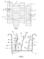
- the figure 1 shows a plan view of a tread comprising elements provided with incisions according to the invention
- the figure 2 shows a sectional cut along the line II-II taken on an element of the figure 1 ;
- a tire tread is limited by external surfaces, one of which is intended to be in contact with a tire structure and another is intended to be in contact with the roadway in use; the direction substantially perpendicular to these two surfaces is said radial direction on the tire. In this direction, the thickness of the strip is measured.
- the figure 1 shows a plan view of a portion of a tread 1 comprising a plurality of relief elements (blocks) 2 delimited by longitudinally oriented grooves 3 (that is to say circumferential on the tire provided with of said band) and transversely oriented grooves 4.
- these relief elements 2 are each provided with several incisions 5 according to the invention, these incisions cutting the running surface 10 create two ridges useful for improving the performance of contact and grip ("grip").
- FIG. figure 2 On the figure 2 a section along line II-II is shown on the strip shown in FIG. figure 1 .
- the incisions are seen in the cutting plane of the incisions 5.
- Each incision comprises three thin sections 51 and two thick sections 52, these thin and thick sections being alternately arranged from the running surface 10 towards the inside of the section. bandaged.
- the section emerging on the running surface in the new state of the strip is a thin section 51 forming a zero angle with a perpendicular to the running surface passing through the intersection point Z0 of the incision 5 with the surface of the strip. bearing 10 in the plane of the figure 2 .
- This first thin section emerging on the running surface is extended towards the inside of the strip by a thick section 52 forming an angle B equal to 100 degrees with the direction perpendicular to the running surface as previously defined.
- the thick sections are at an angle of 10 degrees with a plane parallel to the running surface so as to extend a thin section towards the inside of the strip.
- the thin sections all have the same orientation
- the thick sections all have the same orientation B.
- an angle B equal to 90 degrees corresponds to a direction parallel to the contact face.
- the width E of the thick sections 52 measured perpendicularly to the walls delimiting the incision on the thick section considered, is greater than that of the thin sections 51 and such that under the action of the load alone, the walls 520 delimiting the thick sections 52 are not in contact.
- the width E is in this case 0.8 mm.
- the length P thick sections is an adjustment parameter available to the skilled person to adjust the size of the incision and also to ensure a good locking during certain operations.
- the innermost point Z1 of the incision 5 is here formed by a widening 53 useful for reducing the stress concentrations.
- the thick sections generate corners 6i and 6e of material that can come into contact during a relative displacement of the faces delimiting the thin sections.
- the corners of material 6e are located on the side of the contact face with respect to the corners 6i.
- This point Z1 is projected on the contact face of the element a point Z in the cutting plane of the figure 2 ; in the case where the ground exerts on the contact face a force F tangent to this face and oriented in the direction from the point Z to the point Z0, and after sliding of the faces vis-à-vis the thin sections, the corners 6e come to rely on the corners 6i thus blocking the deformation of the element.
- this incision results in a variable mechanical operation according to the fact that the force F is below a threshold predetermined force Fs or greater than this threshold Fs. Indeed, for forces between zero and the threshold value Fs, the friction forces resulting from the contacts between the walls 510 of the thin sections 51 are sufficient to oppose the relative displacement of said walls. For some F forces greater than the threshold value, the walls of the thin sections in contact will slide relative to each other thus promoting greater deformation of the tread elements and thereby a better contact with the roadway. This sliding is done until the walls of the thick sections come into contact with one another thereby ensuring a blockage of relative movements and therefore the deformation of the band.
- each of these thresholds depends on the limit from which there is a sliding of the walls of the thin sections on each other. This limit and therefore these effort thresholds Fs can be adjusted thanks to various factors at the disposal of the person skilled in the art and in particular:
- the walls 510 of the thin sections can thus slide on each other; the limit of the amplitude of this sliding is substantially equal to the width E of the thick sections 52; this width E is measured parallel to the direction of the thin sections (in this case in a direction perpendicular to the running surface).
- This width E is also a setting parameter available to the skilled person to limit the amplitude of the slip.
- the incision variant 5 shown in section at the figure 3 , comprises three thin sections 51 of width equal to 0.2 mm oriented perpendicularly to the running surface and two thick sections 52 arranged alternately with the thin sections.
- the thick sections have a width equal to 1 mm and are oriented so as to make an average angle B of 80 degrees with a direction perpendicular to the rolling surface: in in the present case, each thick section extends a thin section and is oriented towards the rolling surface 10.
- outer and inner outer corners 6i is shown 6i of material, each outer corner 6e being located on the outside (ie that is to say towards the contact face) with respect to an internal corner 6i, so that each outer corner 6e can come into contact with an internal corner 6i during a sliding of the faces of the thin sections.
- This contacting is possible for a direction of effort F indicated by an arrow on the figure 3 from the ground on the contact face of the element.
- the incision 5 comprises thin portions 51 inclined at an angle A relative to a direction perpendicular to the running surface.
- the direction indicated by the arrow corresponds to the direction of advance R (from the right to the left of the figure in this case).
- the inclination of each thin section is such that the direction joining the obtained Z point as the projection on the running surface of the innermost point Z1 inside the strip and the outermost point Z0 on the surface rolling is opposite to the advancement direction A.
- the thin sections 51 are inclined at an angle a equal to 30 degrees with a direction perpendicular to the rolling surface 10.
- the thick sections 52 are substantially parallel to the running surface. The thickness difference between the thick sections 52 and the thin sections is here greater than 0.3 mm.
- the thin sections are closed and beyond a braking force threshold indicated by the arrow F, the facing faces of these sections will be able to slide some on the others until the outer corners 6e come into contact with the inner corners 6i (the outer corners 6e being located towards the contact face of the element with respect to the inner corners 6i).
- the variant shown with the figure 5 is substantially equivalent to that shown with the figure 4 , the only difference residing in the arrangement of different sections of incision with respect to each other.
- the length H occupied by the incision 5 in the strip corresponds to the length of the perpendicular projection of each of the different thin and thick sections on the running surface 10
- this same length H was equal to the sum of said projections, that is to say to the distance separating the points Z and Z1.
- the thin sections are inclined at an angle A equal to 30 degrees with a direction perpendicular to the running surface and the thick sections are parallel to the running surface.
- outer corners 6e and internal corners 6i each of said corners being formed by a face of a section thin and one side of a thick stump.
- An outer corner 6e is intended to cooperate by contact with an inner corner 6i on an opposite face of the incision 5.
- the variant shown with this figure 5 comprises a chamfer 13 of 1 mm per 1 mm of side (that is to say making an angle equal to 45 degrees with a perpendicular to the running surface) on the trailing edge formed by the incision on the face contact in order to reduce at least in the first kilometers of rolling the wear localized on the trailing edge of the incision as defined by the present invention.
- an incision intersects the running surface along a leading edge (first to enter the contact on the same element) and a trailing edge (last out of the contact).
- the Figures 6 and 7 show the operation of the slat shown with the figure 5 during two braking maneuvers (different amplitudes of effort).
- the tire rolls on a floor S.
- the braking forces are generally greater in amplitude and lead to a contact between the walls of the thick sections: thanks to this contact it is possible to obtain even on dry ground a good performance in adhesion.
- the incision according to the invention which has been shown in blocks can be implemented in ribs. It is possible in particular to combine thin sections of different orientations in the same incision. It is also possible to combine in the same incision thick sections with different inclinations, that is to say that each section has an inclination of its own. It is also possible to combine thin and / or thick sections of different depths and of different widths. For example, an incision according to the invention may be used, the thick sections of which each have a specific thickness, the last thick section having the same thickness. largest thickness,
Landscapes
- Engineering & Computer Science (AREA)
- Mechanical Engineering (AREA)
- Tires In General (AREA)
Claims (5)
- Laufstreifen (1) für einen Autoreifen, wobei dieser Laufstreifen radial außen eine Lauffläche (10) hat, die dazu bestimmt ist, während des Rollens mit der Fahrbahn in Kontakt zu kommen, wobei dieser Streifen eine Vielzahl von Elementen (2) enthält, die durch Ausschnitte begrenzt werden, wobei mindestens bestimmte dieser Elemente mit mindestens einem Einschnitt (5) versehen sind, der von zwei einander gegenüberliegenden Seiten begrenzt wird, wobei dieser Einschnitt aus einer Folge von abwechselnd angeordneten dünnen Abschnitten (51) und dicken Abschnitten (52) besteht, wobei dieser Laufstreifen dadurch gekennzeichnet ist, dass jeder dünne Abschnitt (51) um einen mittleren Winkel A höchstens gleich 40 Grad geneigt ist, wobei dieser Winkel bezüglich einer Richtung lotrecht zur Lauffläche des Streifens gemessen wird und durch die Punkte des Einschnitts an der Lauffläche des Streifens verläuft, wobei jeder dicke Abschnitt (52) einen mittleren Winkel B zwischen 60 Grad und 120 Grad mit einer Richtung lotrecht zur Lauffläche des Streifen bildet, und dass die dünnen Abschnitte (51) eine Breite e geringer als die Breite E der dicken Abschnitte (52) haben, wobei die Breite der dünnen Abschnitte so ist, dass beim Übergang in den Kontakt die die dünnen Abschnitte begrenzenden Wände in Kontakt sind, und die Breite der dicken Abschnitte so ist, dass beim Übergang in den Kontakt die die dicken Abschnitte begrenzenden Wände nicht in Kontakt sind.
- Laufstreifen nach Anspruch 1, dadurch gekennzeichnet, dass die dünnen Einschnittsabschnitte (51) eine Breite höchsten gleich 0,4 mm haben, und dass die dicken Einschnittsabschnitte (52) eine Breite größer als 0,4 mm haben, wobei die Abweichung zwischen den Breiten der dünnen Abschnitte (51) und der dicken Abschnitte (52) mindestens gleich 0,2 mm ist.
- Laufstreifen nach Anspruch 2, dadurch gekennzeichnet, dass die dünnen Einschnittsabschnitte (51) eine Breite höchstens gleich 0,15 mm haben, und dass die dicken Einschnittsabschnitte (52) eine Dicke größer als 0,4 mm haben.
- Laufstreifen nach einem der Ansprüche 1 bis 3, dadurch gekennzeichnet, dass er eine vorgegebene Rollrichtung hat, und dass er einen Anzeiger dieser Rollrichtung aufweist, und dass mindestens ein Einschnitt mindestens einen dünnen Abschnitt (51) und einen dicken Abschnitt (52) enthält, wobei die dünnen Abschnitte (51) so geneigt sind, dass, im Schnitt in einer Ebene lotrecht zur Drehachse des Reifens gesehen, die Richtung des Anzeigers der vorgegebenen Rollrichtung gleich der Drehrichtung ist, um die der dünne Einschnittsabschnitt (51) um seinen am weitesten innerhalb des Streifens befindlichen Punkt gedreht werden muss, um diesen dünnen Abschnitt (51) in eine die Drehachse enthaltende Ebene zu bringen, wobei die dünnen Abschnitte (51) um einen Winkel A mindestens gleich 20 Grad und höchstens gleich 40 Grad zu einer Richtung lotrecht zur Lauffläche 10 geneigt sind.
- Laufstreifen nach einem der Ansprüche 1 bis 4, dadurch gekennzeichnet, dass, wenn jeder Einschnitt (5) die Lauffläche (10) schneidet, um eine Vorderkante und eine Hinterkante zu formen, die Hinterkante eine Abschrägung (13) aufweist.
Applications Claiming Priority (2)
| Application Number | Priority Date | Filing Date | Title |
|---|---|---|---|
| FR0858295A FR2939360B1 (fr) | 2008-12-05 | 2008-12-05 | Bande de roulement pourvue d'incisions |
| PCT/EP2009/066214 WO2010063751A1 (fr) | 2008-12-05 | 2009-12-02 | Bande de roulement pourvue d'incisions. |
Publications (2)
| Publication Number | Publication Date |
|---|---|
| EP2373503A1 EP2373503A1 (de) | 2011-10-12 |
| EP2373503B1 true EP2373503B1 (de) | 2012-10-31 |
Family
ID=40639424
Family Applications (1)
| Application Number | Title | Priority Date | Filing Date |
|---|---|---|---|
| EP09760910A Active EP2373503B1 (de) | 2008-12-05 | 2009-12-02 | Profil mit einschnitten |
Country Status (8)
| Country | Link |
|---|---|
| US (1) | US9211767B2 (de) |
| EP (1) | EP2373503B1 (de) |
| JP (1) | JP5583684B2 (de) |
| CN (1) | CN102227324B (de) |
| BR (1) | BRPI0922142A2 (de) |
| EA (1) | EA018685B1 (de) |
| FR (1) | FR2939360B1 (de) |
| WO (1) | WO2010063751A1 (de) |
Families Citing this family (18)
| Publication number | Priority date | Publication date | Assignee | Title |
|---|---|---|---|---|
| JP6106183B2 (ja) * | 2012-10-24 | 2017-03-29 | 株式会社ブリヂストン | 空気入りタイヤ |
| EP3851296B1 (de) | 2012-12-19 | 2024-10-16 | Bridgestone Americas Tire Operations, LLC | Reifen mit bidirektionaler leistung |
| US10000094B2 (en) | 2013-08-28 | 2018-06-19 | Bridgestone Corporation | Heavy duty pneumatic tire |
| US11752805B2 (en) * | 2016-02-15 | 2023-09-12 | The Yokohama Rubber Co., Ltd. | Pneumatic tire |
| EP3490816B1 (de) * | 2016-07-27 | 2022-03-09 | Bridgestone Americas Tire Operations, LLC | Dreidimensionale reifenlamelle |
| JP6759930B2 (ja) * | 2016-09-26 | 2020-09-23 | 横浜ゴム株式会社 | 空気入りタイヤ |
| JP6828496B2 (ja) * | 2017-02-17 | 2021-02-10 | 横浜ゴム株式会社 | 空気入りタイヤ |
| JP6828495B2 (ja) * | 2017-02-17 | 2021-02-10 | 横浜ゴム株式会社 | 空気入りタイヤ |
| JP6929107B2 (ja) * | 2017-04-10 | 2021-09-01 | 株式会社ブリヂストン | 重荷重用空気入りラジアルタイヤ |
| EP3643525B1 (de) * | 2017-06-19 | 2022-02-23 | Bridgestone Corporation | Reifen |
| US20200369091A1 (en) * | 2017-07-31 | 2020-11-26 | Compagnie Generale Des Etablissments Michelin | Tire tread having tread blocks with inclined trailing side and sipe |
| DE102017213820A1 (de) * | 2017-08-08 | 2019-02-14 | Continental Reifen Deutschland Gmbh | Fahrzeugluftreifen |
| EP3527407B1 (de) * | 2018-02-15 | 2022-05-04 | Nokian Renkaat Oyj | Laufflächenblockanordnung mit einer stützlamelle |
| JP7152361B2 (ja) * | 2019-06-14 | 2022-10-12 | 株式会社ブリヂストン | 空気入りタイヤ |
| WO2022129218A1 (en) | 2020-12-18 | 2022-06-23 | Bridgestone Europe Nv/Sa | Tyre tread with improved sipe on three levels and tyre |
| KR102612469B1 (ko) * | 2021-08-20 | 2023-12-12 | 한국타이어앤테크놀로지 주식회사 | 트레드 블록 강성이 향상된 커프 구조 |
| JP7742491B2 (ja) * | 2021-10-16 | 2025-09-19 | ブリヂストン アメリカズ タイヤ オペレーションズ、 エルエルシー | 方向性相互連結サイプ及び/又はスロット |
| EP4415979A4 (de) * | 2021-10-16 | 2025-08-27 | Bridgestone Americas Tire Operations Llc | Richtungsverriegelnder lamelle und/oder schlitz mit fase |
Family Cites Families (11)
| Publication number | Priority date | Publication date | Assignee | Title |
|---|---|---|---|---|
| FR2612129B1 (fr) * | 1987-03-10 | 1989-09-29 | Michelin & Cie | Bande de roulement pour pneumatique radial dont les elements en relief sont pourvus d'incisions presentant des traces en ligne brisee ou ondulee dans le sens de leurs profondeurs |
| FR2703002B1 (fr) * | 1993-03-25 | 1995-06-02 | Michelin & Cie | Bande de roulement pour pneumatique radial ayant des éléments en relief pourvus d'incisions. |
| DE19650701A1 (de) * | 1996-12-06 | 1998-06-10 | Continental Ag | Fahrzeugluftreifen |
| JPH11151915A (ja) * | 1997-11-21 | 1999-06-08 | Bridgestone Corp | 空気入りタイヤ |
| EP1170153B1 (de) | 2000-07-03 | 2005-12-28 | Société de Technologie Michelin | Luftreifen mit einer Lauffläche für schwere Lasten |
| JP4711373B2 (ja) * | 2001-04-24 | 2011-06-29 | 東洋ゴム工業株式会社 | 空気入りタイヤ |
| ATE320927T1 (de) * | 2001-05-14 | 2006-04-15 | Michelin Soc Tech | Lauffläche mit neigungsvariablen feineinschnitten enthaltenden rippen |
| JP4330455B2 (ja) * | 2004-01-09 | 2009-09-16 | 住友ゴム工業株式会社 | 空気入りタイヤ |
| JP4294507B2 (ja) * | 2004-02-05 | 2009-07-15 | 株式会社ブリヂストン | 空気入りタイヤ |
| US20090000713A1 (en) * | 2007-06-27 | 2009-01-01 | Bridgestone Firestone North American Tire, Llc | Tire including segmented sipes |
| DE102008030810A1 (de) * | 2008-06-28 | 2009-12-31 | Continental Aktiengesellschaft | Fahrzeugluftreifen |
-
2008
- 2008-12-05 FR FR0858295A patent/FR2939360B1/fr not_active Expired - Fee Related
-
2009
- 2009-12-02 EA EA201170760A patent/EA018685B1/ru not_active IP Right Cessation
- 2009-12-02 BR BRPI0922142A patent/BRPI0922142A2/pt not_active IP Right Cessation
- 2009-12-02 WO PCT/EP2009/066214 patent/WO2010063751A1/fr not_active Ceased
- 2009-12-02 JP JP2011539013A patent/JP5583684B2/ja not_active Expired - Fee Related
- 2009-12-02 CN CN2009801479608A patent/CN102227324B/zh not_active Expired - Fee Related
- 2009-12-02 US US13/132,909 patent/US9211767B2/en not_active Expired - Fee Related
- 2009-12-02 EP EP09760910A patent/EP2373503B1/de active Active
Also Published As
| Publication number | Publication date |
|---|---|
| CN102227324A (zh) | 2011-10-26 |
| CN102227324B (zh) | 2013-11-06 |
| US20120132337A1 (en) | 2012-05-31 |
| JP5583684B2 (ja) | 2014-09-03 |
| JP2012510921A (ja) | 2012-05-17 |
| BRPI0922142A2 (pt) | 2016-01-05 |
| FR2939360B1 (fr) | 2011-03-04 |
| EP2373503A1 (de) | 2011-10-12 |
| FR2939360A1 (fr) | 2010-06-11 |
| EA018685B1 (ru) | 2013-09-30 |
| WO2010063751A1 (fr) | 2010-06-10 |
| EA201170760A1 (ru) | 2011-12-30 |
| US9211767B2 (en) | 2015-12-15 |
Similar Documents
| Publication | Publication Date | Title |
|---|---|---|
| EP2373503B1 (de) | Profil mit einschnitten | |
| EP2373502B1 (de) | Reifenlauffläche mit einschnitten, die mit vorsprüngen versehen sind | |
| CA2428572C (fr) | Bande de roulement de pneumatique | |
| EP2588327B1 (de) | Reifenprofil mit verringertem rollgeräusch | |
| EP1170153B1 (de) | Luftreifen mit einer Lauffläche für schwere Lasten | |
| EP2013037B1 (de) | Sperrteile umfassender laufstreifeneinschnitt | |
| EP1506099B1 (de) | Skalierbarer laufstreifen | |
| EP2563604B1 (de) | Profil für einen reifen für schwerlastfahrzeuge vom anhängertyp | |
| FR2931728A1 (fr) | Pneumatique pour roulage sur glace | |
| FR2933335A1 (fr) | Bande de roulement directionnelle pour pneu pourvue d'incisions adaptees | |
| CH628293A5 (fr) | Pneumatique destine a rouler sur la neige. | |
| EP2661376B1 (de) | Reifen für schwerlastfahrzeug und anordnung von reifen auf lenkachse und auf antriebachse | |
| WO2014082922A1 (fr) | Bande de roulement pour pneumatique neige comportant des incisions et des cavites | |
| EP2318219B1 (de) | Reifenlauffläche mit laufrichtungsgebundenem profil | |
| EP3658390B1 (de) | Reifen mit lauffläche mit einem sich entwickelnden laufflächenprofil mit lamellen | |
| EP3802154B1 (de) | Reifenlauffläche mit gewellten rillen und lamellen | |
| WO2017016931A1 (fr) | Bande de roulement pour pneu de poids lourd ameliorant le bruit en roulage | |
| FR2954221A1 (fr) | Pneu a performance de roulage amelioree | |
| EP1283115B1 (de) | Oberflächenprofil der Elemente der Reifenlauffläche | |
| EP2373500B1 (de) | Einschnitte und aussparungen umfassendes reifenprofil | |
| EP3681737B1 (de) | Form für eine reifenlauffläche mit verdeckten kanälen | |
| FR2953453A1 (fr) | Bande de roulement pour pneumatique | |
| FR2953454A1 (fr) | Bande de roulement pour pneumatique |
Legal Events
| Date | Code | Title | Description |
|---|---|---|---|
| PUAI | Public reference made under article 153(3) epc to a published international application that has entered the european phase |
Free format text: ORIGINAL CODE: 0009012 |
|
| 17P | Request for examination filed |
Effective date: 20110705 |
|
| AK | Designated contracting states |
Kind code of ref document: A1 Designated state(s): AT BE BG CH CY CZ DE DK EE ES FI FR GB GR HR HU IE IS IT LI LT LU LV MC MK MT NL NO PL PT RO SE SI SK SM TR |
|
| DAX | Request for extension of the european patent (deleted) | ||
| GRAP | Despatch of communication of intention to grant a patent |
Free format text: ORIGINAL CODE: EPIDOSNIGR1 |
|
| RAP1 | Party data changed (applicant data changed or rights of an application transferred) |
Owner name: MICHELIN RECHERCHE ET TECHNIQUE S.A. Owner name: COMPAGNIE GENERALE DES ETABLISSEMENTS MICHELIN |
|
| GRAS | Grant fee paid |
Free format text: ORIGINAL CODE: EPIDOSNIGR3 |
|
| GRAA | (expected) grant |
Free format text: ORIGINAL CODE: 0009210 |
|
| AK | Designated contracting states |
Kind code of ref document: B1 Designated state(s): AT BE BG CH CY CZ DE DK EE ES FI FR GB GR HR HU IE IS IT LI LT LU LV MC MK MT NL NO PL PT RO SE SI SK SM TR |
|
| REG | Reference to a national code |
Ref country code: GB Ref legal event code: FG4D Free format text: NOT ENGLISH Ref country code: CH Ref legal event code: EP |
|
| REG | Reference to a national code |
Ref country code: AT Ref legal event code: REF Ref document number: 581784 Country of ref document: AT Kind code of ref document: T Effective date: 20121115 |
|
| REG | Reference to a national code |
Ref country code: IE Ref legal event code: FG4D Free format text: LANGUAGE OF EP DOCUMENT: FRENCH |
|
| REG | Reference to a national code |
Ref country code: DE Ref legal event code: R096 Ref document number: 602009010873 Country of ref document: DE Effective date: 20121227 |
|
| REG | Reference to a national code |
Ref country code: AT Ref legal event code: MK05 Ref document number: 581784 Country of ref document: AT Kind code of ref document: T Effective date: 20121031 |
|
| REG | Reference to a national code |
Ref country code: LT Ref legal event code: MG4D |
|
| REG | Reference to a national code |
Ref country code: NL Ref legal event code: VDEP Effective date: 20121031 |
|
| PG25 | Lapsed in a contracting state [announced via postgrant information from national office to epo] |
Ref country code: HR Free format text: LAPSE BECAUSE OF FAILURE TO SUBMIT A TRANSLATION OF THE DESCRIPTION OR TO PAY THE FEE WITHIN THE PRESCRIBED TIME-LIMIT Effective date: 20121031 Ref country code: NO Free format text: LAPSE BECAUSE OF FAILURE TO SUBMIT A TRANSLATION OF THE DESCRIPTION OR TO PAY THE FEE WITHIN THE PRESCRIBED TIME-LIMIT Effective date: 20130131 Ref country code: IS Free format text: LAPSE BECAUSE OF FAILURE TO SUBMIT A TRANSLATION OF THE DESCRIPTION OR TO PAY THE FEE WITHIN THE PRESCRIBED TIME-LIMIT Effective date: 20130228 Ref country code: SE Free format text: LAPSE BECAUSE OF FAILURE TO SUBMIT A TRANSLATION OF THE DESCRIPTION OR TO PAY THE FEE WITHIN THE PRESCRIBED TIME-LIMIT Effective date: 20121031 Ref country code: FI Free format text: LAPSE BECAUSE OF FAILURE TO SUBMIT A TRANSLATION OF THE DESCRIPTION OR TO PAY THE FEE WITHIN THE PRESCRIBED TIME-LIMIT Effective date: 20121031 Ref country code: NL Free format text: LAPSE BECAUSE OF FAILURE TO SUBMIT A TRANSLATION OF THE DESCRIPTION OR TO PAY THE FEE WITHIN THE PRESCRIBED TIME-LIMIT Effective date: 20121031 Ref country code: LT Free format text: LAPSE BECAUSE OF FAILURE TO SUBMIT A TRANSLATION OF THE DESCRIPTION OR TO PAY THE FEE WITHIN THE PRESCRIBED TIME-LIMIT Effective date: 20121031 |
|
| PG25 | Lapsed in a contracting state [announced via postgrant information from national office to epo] |
Ref country code: PT Free format text: LAPSE BECAUSE OF FAILURE TO SUBMIT A TRANSLATION OF THE DESCRIPTION OR TO PAY THE FEE WITHIN THE PRESCRIBED TIME-LIMIT Effective date: 20130228 Ref country code: SI Free format text: LAPSE BECAUSE OF FAILURE TO SUBMIT A TRANSLATION OF THE DESCRIPTION OR TO PAY THE FEE WITHIN THE PRESCRIBED TIME-LIMIT Effective date: 20121031 Ref country code: PL Free format text: LAPSE BECAUSE OF FAILURE TO SUBMIT A TRANSLATION OF THE DESCRIPTION OR TO PAY THE FEE WITHIN THE PRESCRIBED TIME-LIMIT Effective date: 20121031 Ref country code: LV Free format text: LAPSE BECAUSE OF FAILURE TO SUBMIT A TRANSLATION OF THE DESCRIPTION OR TO PAY THE FEE WITHIN THE PRESCRIBED TIME-LIMIT Effective date: 20121031 Ref country code: GR Free format text: LAPSE BECAUSE OF FAILURE TO SUBMIT A TRANSLATION OF THE DESCRIPTION OR TO PAY THE FEE WITHIN THE PRESCRIBED TIME-LIMIT Effective date: 20130201 |
|
| PG25 | Lapsed in a contracting state [announced via postgrant information from national office to epo] |
Ref country code: AT Free format text: LAPSE BECAUSE OF FAILURE TO SUBMIT A TRANSLATION OF THE DESCRIPTION OR TO PAY THE FEE WITHIN THE PRESCRIBED TIME-LIMIT Effective date: 20121031 |
|
| BERE | Be: lapsed |
Owner name: MICHELIN RECHERCHE ET TECHNIQUE S.A. Effective date: 20121231 Owner name: CIE GENERALE DES ETABLISSEMENTS MICHELIN Effective date: 20121231 |
|
| PG25 | Lapsed in a contracting state [announced via postgrant information from national office to epo] |
Ref country code: MC Free format text: LAPSE BECAUSE OF NON-PAYMENT OF DUE FEES Effective date: 20121231 Ref country code: DK Free format text: LAPSE BECAUSE OF FAILURE TO SUBMIT A TRANSLATION OF THE DESCRIPTION OR TO PAY THE FEE WITHIN THE PRESCRIBED TIME-LIMIT Effective date: 20121031 Ref country code: SK Free format text: LAPSE BECAUSE OF FAILURE TO SUBMIT A TRANSLATION OF THE DESCRIPTION OR TO PAY THE FEE WITHIN THE PRESCRIBED TIME-LIMIT Effective date: 20121031 Ref country code: BG Free format text: LAPSE BECAUSE OF FAILURE TO SUBMIT A TRANSLATION OF THE DESCRIPTION OR TO PAY THE FEE WITHIN THE PRESCRIBED TIME-LIMIT Effective date: 20130131 Ref country code: EE Free format text: LAPSE BECAUSE OF FAILURE TO SUBMIT A TRANSLATION OF THE DESCRIPTION OR TO PAY THE FEE WITHIN THE PRESCRIBED TIME-LIMIT Effective date: 20121031 Ref country code: CZ Free format text: LAPSE BECAUSE OF FAILURE TO SUBMIT A TRANSLATION OF THE DESCRIPTION OR TO PAY THE FEE WITHIN THE PRESCRIBED TIME-LIMIT Effective date: 20121031 |
|
| PG25 | Lapsed in a contracting state [announced via postgrant information from national office to epo] |
Ref country code: RO Free format text: LAPSE BECAUSE OF FAILURE TO SUBMIT A TRANSLATION OF THE DESCRIPTION OR TO PAY THE FEE WITHIN THE PRESCRIBED TIME-LIMIT Effective date: 20121031 |
|
| PLBE | No opposition filed within time limit |
Free format text: ORIGINAL CODE: 0009261 |
|
| STAA | Information on the status of an ep patent application or granted ep patent |
Free format text: STATUS: NO OPPOSITION FILED WITHIN TIME LIMIT |
|
| REG | Reference to a national code |
Ref country code: IE Ref legal event code: MM4A |
|
| PG25 | Lapsed in a contracting state [announced via postgrant information from national office to epo] |
Ref country code: BE Free format text: LAPSE BECAUSE OF NON-PAYMENT OF DUE FEES Effective date: 20121231 |
|
| 26N | No opposition filed |
Effective date: 20130801 |
|
| PG25 | Lapsed in a contracting state [announced via postgrant information from national office to epo] |
Ref country code: ES Free format text: LAPSE BECAUSE OF FAILURE TO SUBMIT A TRANSLATION OF THE DESCRIPTION OR TO PAY THE FEE WITHIN THE PRESCRIBED TIME-LIMIT Effective date: 20130211 Ref country code: IE Free format text: LAPSE BECAUSE OF NON-PAYMENT OF DUE FEES Effective date: 20121202 |
|
| REG | Reference to a national code |
Ref country code: DE Ref legal event code: R097 Ref document number: 602009010873 Country of ref document: DE Effective date: 20130801 |
|
| PG25 | Lapsed in a contracting state [announced via postgrant information from national office to epo] |
Ref country code: MT Free format text: LAPSE BECAUSE OF FAILURE TO SUBMIT A TRANSLATION OF THE DESCRIPTION OR TO PAY THE FEE WITHIN THE PRESCRIBED TIME-LIMIT Effective date: 20121031 Ref country code: CY Free format text: LAPSE BECAUSE OF FAILURE TO SUBMIT A TRANSLATION OF THE DESCRIPTION OR TO PAY THE FEE WITHIN THE PRESCRIBED TIME-LIMIT Effective date: 20121031 |
|
| PG25 | Lapsed in a contracting state [announced via postgrant information from national office to epo] |
Ref country code: TR Free format text: LAPSE BECAUSE OF FAILURE TO SUBMIT A TRANSLATION OF THE DESCRIPTION OR TO PAY THE FEE WITHIN THE PRESCRIBED TIME-LIMIT Effective date: 20121031 |
|
| PG25 | Lapsed in a contracting state [announced via postgrant information from national office to epo] |
Ref country code: SM Free format text: LAPSE BECAUSE OF FAILURE TO SUBMIT A TRANSLATION OF THE DESCRIPTION OR TO PAY THE FEE WITHIN THE PRESCRIBED TIME-LIMIT Effective date: 20121031 Ref country code: LU Free format text: LAPSE BECAUSE OF NON-PAYMENT OF DUE FEES Effective date: 20121202 |
|
| PG25 | Lapsed in a contracting state [announced via postgrant information from national office to epo] |
Ref country code: HU Free format text: LAPSE BECAUSE OF FAILURE TO SUBMIT A TRANSLATION OF THE DESCRIPTION OR TO PAY THE FEE WITHIN THE PRESCRIBED TIME-LIMIT Effective date: 20091202 |
|
| REG | Reference to a national code |
Ref country code: CH Ref legal event code: PL |
|
| GBPC | Gb: european patent ceased through non-payment of renewal fee |
Effective date: 20131202 |
|
| PG25 | Lapsed in a contracting state [announced via postgrant information from national office to epo] |
Ref country code: LI Free format text: LAPSE BECAUSE OF NON-PAYMENT OF DUE FEES Effective date: 20131231 Ref country code: CH Free format text: LAPSE BECAUSE OF NON-PAYMENT OF DUE FEES Effective date: 20131231 |
|
| PG25 | Lapsed in a contracting state [announced via postgrant information from national office to epo] |
Ref country code: GB Free format text: LAPSE BECAUSE OF NON-PAYMENT OF DUE FEES Effective date: 20131202 |
|
| PG25 | Lapsed in a contracting state [announced via postgrant information from national office to epo] |
Ref country code: MK Free format text: LAPSE BECAUSE OF FAILURE TO SUBMIT A TRANSLATION OF THE DESCRIPTION OR TO PAY THE FEE WITHIN THE PRESCRIBED TIME-LIMIT Effective date: 20121031 |
|
| PG25 | Lapsed in a contracting state [announced via postgrant information from national office to epo] |
Ref country code: IT Free format text: LAPSE BECAUSE OF NON-PAYMENT OF DUE FEES Effective date: 20131231 |
|
| REG | Reference to a national code |
Ref country code: FR Ref legal event code: PLFP Year of fee payment: 7 |
|
| PG25 | Lapsed in a contracting state [announced via postgrant information from national office to epo] |
Ref country code: IT Free format text: LAPSE BECAUSE OF NON-PAYMENT OF DUE FEES Effective date: 20131202 |
|
| REG | Reference to a national code |
Ref country code: FR Ref legal event code: PLFP Year of fee payment: 8 |
|
| REG | Reference to a national code |
Ref country code: FR Ref legal event code: PLFP Year of fee payment: 9 |
|
| PGFP | Annual fee paid to national office [announced via postgrant information from national office to epo] |
Ref country code: DE Payment date: 20191210 Year of fee payment: 11 |
|
| REG | Reference to a national code |
Ref country code: DE Ref legal event code: R119 Ref document number: 602009010873 Country of ref document: DE |
|
| PG25 | Lapsed in a contracting state [announced via postgrant information from national office to epo] |
Ref country code: DE Free format text: LAPSE BECAUSE OF NON-PAYMENT OF DUE FEES Effective date: 20210701 |
|
| PGFP | Annual fee paid to national office [announced via postgrant information from national office to epo] |
Ref country code: FR Payment date: 20241223 Year of fee payment: 16 |