EP2318219B1 - Tyre tread with directional pattern - Google Patents
Tyre tread with directional pattern Download PDFInfo
- Publication number
- EP2318219B1 EP2318219B1 EP09809306A EP09809306A EP2318219B1 EP 2318219 B1 EP2318219 B1 EP 2318219B1 EP 09809306 A EP09809306 A EP 09809306A EP 09809306 A EP09809306 A EP 09809306A EP 2318219 B1 EP2318219 B1 EP 2318219B1
- Authority
- EP
- European Patent Office
- Prior art keywords
- tread
- grooves
- additional
- main
- groove
- Prior art date
- Legal status (The legal status is an assumption and is not a legal conclusion. Google has not performed a legal analysis and makes no representation as to the accuracy of the status listed.)
- Not-in-force
Links
Images


Classifications
-
- B—PERFORMING OPERATIONS; TRANSPORTING
- B60—VEHICLES IN GENERAL
- B60C—VEHICLE TYRES; TYRE INFLATION; TYRE CHANGING; CONNECTING VALVES TO INFLATABLE ELASTIC BODIES IN GENERAL; DEVICES OR ARRANGEMENTS RELATED TO TYRES
- B60C11/00—Tyre tread bands; Tread patterns; Anti-skid inserts
- B60C11/03—Tread patterns
- B60C11/0302—Tread patterns directional pattern, i.e. with main rolling direction
-
- B—PERFORMING OPERATIONS; TRANSPORTING
- B60—VEHICLES IN GENERAL
- B60C—VEHICLE TYRES; TYRE INFLATION; TYRE CHANGING; CONNECTING VALVES TO INFLATABLE ELASTIC BODIES IN GENERAL; DEVICES OR ARRANGEMENTS RELATED TO TYRES
- B60C11/00—Tyre tread bands; Tread patterns; Anti-skid inserts
- B60C11/03—Tread patterns
- B60C2011/0337—Tread patterns characterised by particular design features of the pattern
- B60C2011/0339—Grooves
- B60C2011/0374—Slant grooves, i.e. having an angle of about 5 to 35 degrees to the equatorial plane
-
- B—PERFORMING OPERATIONS; TRANSPORTING
- B60—VEHICLES IN GENERAL
- B60C—VEHICLE TYRES; TYRE INFLATION; TYRE CHANGING; CONNECTING VALVES TO INFLATABLE ELASTIC BODIES IN GENERAL; DEVICES OR ARRANGEMENTS RELATED TO TYRES
- B60C11/00—Tyre tread bands; Tread patterns; Anti-skid inserts
- B60C11/03—Tread patterns
- B60C2011/0337—Tread patterns characterised by particular design features of the pattern
- B60C2011/0386—Continuous ribs
- B60C2011/0388—Continuous ribs provided at the equatorial plane
Definitions
- the present invention relates to tires for passenger vehicles and more particularly the treads which are provided with said tires, and even more particularly, tires intended to be mounted on high performance vehicles.
- a directional tire comprises a tread having a directional tread such that, when the tire is rotated in the preferred direction, this tire provides better ground adhesion properties than those offered when rotating in the tread. other way.
- carving a tread is meant a plurality of cutouts made in said tread in a suitable pattern, said cutouts having equally suitable widths and depths. Cutouts means either grooves or incisions, the latter (incisions) being distinguished from the first by widths (distance between the facing faces) generally less than 2 mm and even more preferably less than 1 mm).
- a directional tread pattern has main grooves which are arranged to form a series of V-grooves all pointing in the same direction around the tread of the tire.
- the V-shaped grooves point in the direction of travel, so that the middle part (near the median plane of the tire) of each groove V-shaped is the first on the footprint of the tire on the ground.
- the transverse thrust curve as a function of the drift angle of such a tire has a characteristic appearance showing an increase in said transverse thrust to a maximum followed by a significant reduction in transverse thrust for strong drifts (an example of such a curve is shown with the curve C0 on the figure 2 of this document).
- EP0721853 shows a variant of such a sculpture according to which a plurality of additional grooves have been introduced. Some of these additional grooves are formed to connect in pairs the main grooves located on the same side of the tread with respect to the median plane. Other additional grooves are formed to connect in pairs the main grooves located on either side of the median plane. By groove connected to another groove, it should be understood that an additional groove opens at its ends in main grooves.
- additional grooves are here oriented so as to be substantially perpendicular to the main grooves they connect.
- a first additional groove is formed between the axially inner end of a main groove and a second main groove so as to be substantially perpendicular to the second main groove.
- This first additional groove forms with the circumferential direction an angle close to 45 degrees.
- a second additional groove is formed axially outside this first additional groove.
- the main grooves and the first additional grooves delimit a plurality of discontinuous elements in the circumferential direction, some of whose edges are subjected to high overpressures during the steering maneuvers (that is to say in particular under strong transverse accelerations).
- An object of the invention is to propose a sculpture for a tire tread fitted to a passenger vehicle which does not have the drawbacks mentioned above and in particular does not show a significant drop in the drifting thrust with high transverse stresses (in particular turn).
- the subject of the invention is a tread for a tire, as defined in claims 1 and 5, provided with a tread comprising a plurality of main grooves formed on each half of the tread of the tread and other median plane, each of these main grooves of average width L opening axially outside the strip and extending axially inside to a distance from the median plane of the strip between 2.5 and 10 % of the width TW of the tread.
- These main grooves form a generally V-shaped pattern giving this tread a preferential rolling direction such that the axially innermost end of each main groove comes into contact with the roadway before the axially end. the most outside of the same main groove.
- each additional groove - i.e., the closest to said plane - is at a distance D1 from the equatorial plane which is greater than the distance from the same plane of the first ends of the grooves. and less than 18% of the width TW of the strip.
- This tread is such that on each main groove opens at least one additional groove and in that the axially innermost end of each additional groove comes into contact with the roadway before the axially most end. the outside of the same additional groove.
- the tread according to the invention therefore comprises a median portion which extends in the circumferential direction and whose axially opposite edges delimit a plurality of spikes which give the tread good performance both on wet and on dry pavement.
- the median portion of the strip located on either side of the median plane and which is delimited by the main grooves and the additional grooves has a transverse shear stress rigidity which is equal or substantially equal (that is, that is to say very little different) from that of a part of the same geometry and devoid of any cut-out (groove, incision) so as to be able to carry out a total transfer of forces from one side of this part to the other side in the axial direction.
- This middle portion is in particular devoid of circumferential groove. Thanks to a tread according to the invention it is possible to obtain a homogeneous operation of said strip and in particular an almost homogeneous distribution of the contact pressures on this median part by avoiding rocking mechanisms of the elements of matter in this middle part. .
- the additional grooves open on the main grooves only at one end, the other end being distant from another main groove by a distance of less than 50% of the average distance between two main grooves measured in the direction of the additional groove (and even more preferably less than 25% of said distance).
- each additional groove opens at its two ends in main grooves on the same half of the tread.
- the presence of the additional grooves according to the invention makes it possible to improve the shape of the tire thrust curves as a function of the drift angle and, consequently, to improve the equilibrium of the vehicle during specific maneuvers under very strong conditions. transverse accelerations.
- the additional grooves have an average width of at least 1.5 mm and at most equal to 4 mm.
- the plurality of the main grooves formed on one half of the tread is shifted circumferentially with respect to the plurality of the main grooves formed on the other half of the tread.
- additional second grooves connect the main grooves in pairs, these second additional grooves being substantially parallel to the first additional grooves and located at a distance from the equatorial plane between 27 and 37% of the width TW of the tread.
- substantially parallel is meant here that the grooves additional on the same side of the strip have between them a zero angular difference or up to 5 degrees.
- the depths of the first and second additional grooves are at least equal to 50% of the depth of the main grooves.
- FIG. 1 shows a partial view in elevation of a tread according to the invention
- FIG. 3 shows a partial view in elevation of a tread according to a variant of the invention.
- FIG. 4 shows a partial view in elevation of a tread according to another variant of the invention.
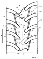
- FIG. 1 shows a partial view in elevation of a part of a tread for a passenger vehicle tire of dimension 195/65 R 15.
- This tire with a radial carcass reinforcement comprises a tread 1 coming into contact of the ground, this band having two lateral edges 12 and 13 spaced from each other by a tread width TW.
- the lateral edges 12 and 13 correspond to the axially outermost points of the tread coming into contact with the roadway, the tire being subjected to nominal pressure and load conditions.
- the tread width TW is defined as being the greatest axial distance of the tire, measured from the footprint of the tire when it is mounted on a given rim and is inflated to a pressure of use under a nominal load; the terms “axial” and “axial” refer to distances taken along or parallel to the axis of rotation of the tire.
- the tread 1 extends beyond its lateral edges 12 and 13 by flanks to beads.
- the tire provided with such a strip has a median circumferential plane (said medial plane X-X ') which is perpendicular to the axis of rotation of the tire and is located midway between the lateral edges 12 and 13 of the strip
- the tread is provided on its radially outer surface with a directional tread formed of main grooves 15 and 16 disposed on each half of the tread (i.e., on each part of the tread strip). rolling on both sides of the median plane X-X ').
- the direction of rotation is indicated by an arrow R in the drawings (this same type of marking may be used on the tire provided with this band to indicate the recommended direction of travel in order to have all the advantages of the invention).
- the main grooves 15 and 16 extend from a medial circumferential portion 17 which is symmetrically disposed on either side of the median plane X-X ', towards a corresponding lateral edge 12 or 13.
- medial circumferential portion of the tread means a portion extending up to at most 28% of the bandwidth TW on each side of the median plane X-X '.
- Each main groove 15 (respectively 16) comprises a first end 151 (respectively 161) and a second end 152 (respectively 162).
- the first ends 151, 161 are located in the middle circumferential portion 17 without being located on the median plane X-X '.
- the axial distance D0 between each of these first ends and the median plane XX ' is equal to 4% of the width TW of the tread (in the example shown, the distances of the first ends of the main grooves both halves of the band are equal).
- the second ends 152, 162 of the main grooves open on the lateral edges 12, 13 of the tread.
- the main grooves 15, 16 have average widths ranging from 5 mm to 8.5 mm and a mean depth equal to 8.5 mm and are arranged to generate generally a V- shaped pattern ; the tip of this V indicating the preferred direction of rotation chosen for this sculpture.
- the geometric shape of each main groove is such that the angle T of the tangent to the ridges formed on the tread by these main grooves with a direction contained in the median plane XX 'increases with the distance between the point of tangency considered and said plane.
- the main grooves 15 of a half of the tread are circumferentially offset from the main grooves 16 of the other half.
- the offset is substantially equal to half the distance between adjacent main grooves on the same tread half.
- the main grooves may not be circumferentially offset from one another.
- this sculpture comprises on each half of the tread and entirely contained in the medial circumferential portion 17, a plurality of additional grooves 20 of width equal to 3 mm and of average orientation A equal in this case to 4 degrees, this orientation being measured with respect to a direction tangent to the circumferential direction.
- Each additional groove 20 comprises a first end 21 and a second end 22, the first end 21 being situated at an axial distance D1 from the median plane XX 'which is here equal to 13% of the width TW of the tread , the second end 22 being located at an axial distance D2 of the median plane XX 'which is equal to 14% of the width TW of the tread.
- each additional groove 20 opens at its two ends in main grooves 15, 16 consecutive of the same half of the tread.
- the angle A of the additional grooves with the circumferential direction is small, that is to say greater than zero degrees and at most equal to 20 degrees; even more preferably, the angle A is at least 4 degrees and at most 15 degrees.
- the figure 2 shows a comparison of the transverse thrust curves Fy recorded with a tire according to the invention (curve Ci) which has just been described and a tire according to the prior art (curve C), the latter being identical to the tire of the invention with the difference that it is provided with additional grooves at an angle of 30 degrees with a tangent to the circumferential direction. It can be seen that for values of drift angle ⁇ greater than the drift giving the maximum thrusts, whereas for the tire of the prior art there is a significant loss of the transverse thrust of the ground on the tire, the tire of the invention records a thrust of almost constant value.
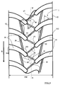
- the variant according to the invention which has just been described with the support of the figure 1 can further be improved by providing the medial circumferential portion 17 with a plurality of oblique grooves 40 connecting the ends 151 of the main grooves 15 of one tread half to the ends 161 of the main grooves 16 on the other tread half as shown with the figure 3 .
- oblique grooves 40 it is essential to provide these oblique grooves 40 with protuberances 41 which prevent the closing of these grooves while transferring in full the transverse forces (parallel to the axis of rotation) on one side of the circumferential central part to the other side of the same part.
- transverse of the medial circumferential portion 17 while benefiting from additional edges useful especially on pavement covered with water.
- the protuberances are arranged on the walls defining the oblique grooves 40 so as to be present regardless of the level of wear of the strip.
- these oblique grooves 40 have widths equal to the widths of the additional grooves 20 and have a depth equal to the depth of the additional grooves.
- the figure 4 shows a variant of sculpture according to the invention for a tread fitted to a tire of the same size as that used for the figure 1 .
- the same references are used to designate the same structural elements.
- the additional grooves 20 open only through a first end 21 in a main groove 15 (or 16).
- the distance H between the second end 22 and the neighboring main groove is less than 50% of the distance D3 measured between two main grooves in the direction of the additional groove and in the variant shown this distance H is equal to 20% of the distance D3.
- the middle portion of the tread is delimited by the main grooves and the additional grooves, the latter being virtually extended to another main groove.
Abstract
Description
La présente invention concerne les pneus pour véhicules de tourisme et plus particulièrement les bandes de roulement dont sont pourvues lesdits pneus, et encore plus particulièrement, les pneus destinés à être montés sur des véhicules à hautes performances.The present invention relates to tires for passenger vehicles and more particularly the treads which are provided with said tires, and even more particularly, tires intended to be mounted on high performance vehicles.
Il est connu de former des sculptures de bande de roulement de manière à conférer à ladite bande de roulement un caractère directionnel. Un pneu directionnel comprend une bande de roulement ayant une sculpture directionnelle telle que, lorsqu'on fait tourner le pneu dans le sens préférentiel, ce pneu offre des propriétés d'adhérence au sol meilleures que celles offertes lorsqu'on le fait tourner dans l'autre sens. Par sculpture d'une bande de roulement, on entend une pluralité de découpures réalisées dans ladite bande suivant un dessin approprié, lesdites découpures ayant des largeurs et profondeurs également appropriées. Par découpures on entend soit des rainures soit des incisions, ces dernières (incisions) se distinguant des premières par des largeurs (distance entre les faces en vis-à-vis) généralement inférieures à 2 mm et encore plus préférentiellement inférieur à 1 mm).It is known to form tread patterns so as to impart to said tread a directional character. A directional tire comprises a tread having a directional tread such that, when the tire is rotated in the preferred direction, this tire provides better ground adhesion properties than those offered when rotating in the tread. other way. By carving a tread is meant a plurality of cutouts made in said tread in a suitable pattern, said cutouts having equally suitable widths and depths. Cutouts means either grooves or incisions, the latter (incisions) being distinguished from the first by widths (distance between the facing faces) generally less than 2 mm and even more preferably less than 1 mm).
Une sculpture directionnelle de bande usuelle présente des rainures principales qui sont disposées de manière à constituer une série de rainures en V pointant toutes dans la même direction tout autour de la bande de roulement du pneu. Habituellement, pour une adhérence au sol maximale au cours de l'accélération des véhicules à hautes performances, les rainures en forme de V pointent dans la direction du déplacement, si bien que la partie médiane (proche du plan médian du pneu) de chaque rainure en forme de V se présente la première sur l'empreinte du pneu au sol.A directional tread pattern has main grooves which are arranged to form a series of V-grooves all pointing in the same direction around the tread of the tire. Usually, for maximum ground adhesion during the acceleration of high performance vehicles, the V-shaped grooves point in the direction of travel, so that the middle part (near the median plane of the tire) of each groove V-shaped is the first on the footprint of the tire on the ground.
Des exemples de ce genre de pneus sont présentés dans la demande de brevet
Si ces sculptures présentent un avantage certain en roulage sur chaussée revêtue d'eau, on observe que ce type de sculpture peut présenter des inconvénients lors de tests de comportement routier sur chaussée sèche lorsqu'on se place aux limites d'adhérence en virage notamment. En effet, la courbe de poussée transversale en fonction de l'angle de dérive d'un tel pneumatique présente une allure caractéristique montrant une augmentation de ladite poussée transversale jusqu'à un maximum suivi par une diminution sensible de poussée transversale pour des fortes dérives (un exemple d'une telle courbe est montrée avec la courbe repérée C0 sur la
Aux fortes accélérations, et pour certaines manoeuvres spécifiques telles que du "surbraquage" ou braquage en limite d'adhérence pour des accélérations latérales supérieures à 0.8 fois l'accélération de la pesanteur, cela peut se traduire par une dégradation de l'équilibre du véhicule équipé de pneus pourvus de telles sculptures.At high acceleration, and for certain specific maneuvers such as "overbraking" or tack-free steering for side accelerations greater than 0.8 times the acceleration of gravity, this can result in a degradation of the vehicle balance equipped with tires provided with such sculptures.
Le document de brevet
Ces rainures additionnelles sont ici orientées de manières à être sensiblement perpendiculaires aux rainures principales qu'elles relient. Entre deux rainures principales, une première rainure additionnelle est formée entre l'extrémité axialement à l'intérieur d'une rainure principale et une deuxième rainure principale de manière à être sensiblement perpendiculaire à la deuxième rainure principale. Cette première rainure additionnelle forme avec la direction circonférentielle un angle voisin de 45 degrés. Une deuxième rainure additionnelle est formée axialement à l'extérieur de cette première rainure additionnelle. Selon cet art antérieur, les rainures principales et les premières rainures additionnelles délimitent une pluralité d'éléments discontinus dans la direction circonférentielle dont certaines des arêtes sont soumises à de fortes surpressions pendant les manoeuvres de braquage (c'est-à-dire notamment sous fortes accélérations transversales). Les rainures additionnelles de cet art antérieur sont défavorables d'un point de vue rigidité transversale : en effet, lorsque cette bande est soumise à un effort transversal notamment en manoeuvre de braquage, on constate une perte sensible de rigidité provoquant une diminution de la poussée de dérive.These additional grooves are here oriented so as to be substantially perpendicular to the main grooves they connect. Between two main grooves, a first additional groove is formed between the axially inner end of a main groove and a second main groove so as to be substantially perpendicular to the second main groove. This first additional groove forms with the circumferential direction an angle close to 45 degrees. A second additional groove is formed axially outside this first additional groove. According to this prior art, the main grooves and the first additional grooves delimit a plurality of discontinuous elements in the circumferential direction, some of whose edges are subjected to high overpressures during the steering maneuvers (that is to say in particular under strong transverse accelerations). The additional grooves of this prior art are unfavorable from a transverse rigidity point of view: indeed, when this strip is subjected to a transverse force, notably in steering maneuvering, there is a significant loss of rigidity causing a decrease in the thrust of derivative.
Un objectif de l'invention est de proposer une sculpture pour bande de roulement de pneu équipant véhicule de tourisme ne présentant pas les inconvénients rappelés plus haut et en particulier ne montrant pas de, chute sensible de la poussée de dérive à forte sollicitations transversales (en virage).An object of the invention is to propose a sculpture for a tire tread fitted to a passenger vehicle which does not have the drawbacks mentioned above and in particular does not show a significant drop in the drifting thrust with high transverse stresses (in particular turn).
A cet effet, l'invention a pour objet une bande de roulement pour pneu, telle que définie dans les revendications 1 et 5, pourvue d'une sculpture comprenant une pluralité de rainures principales formées sur chaque moitié de la bande de roulement de part et d'autre plan médian, chacune de ces rainures principales de largeur moyenne L s'ouvrant axialement à l'extérieur de la bande et se prolongeant axialement à l'intérieur jusqu'à une distance du plan médian de la bande comprise entre 2.5 et 10% de la largeur TW de la bande de roulement. Ces rainures principales forment un motif de forme générale en V conférant à cette bande de roulement un sens de roulement préférentiel tel que l'extrémité axialement la plus à l'intérieur de chaque rainure principale rentre dans le contact avec la chaussée avant l'extrémité axialement la plus à l'extérieur de la même rainure principale.To this end, the subject of the invention is a tread for a tire, as defined in
Il est en outre prévu une pluralité de rainures additionnelles de largeur 1 inférieure à la largeur moyenne L des rainures principales et comprenant une première et une seconde extrémités, la direction moyenne reliant les première et seconde extrémités formant avec la direction circonférentielle un angle A faible, c'est-à-dire au plus égal à 20 degrés et supérieur à zéro degré, la seconde extrémité étant située à une distance D2 du plan médian qui est supérieure à la distance D1 séparant du même plan la première extrémité, au moins la première ou la seconde extrémité étant ouverte sur une rainure principale. En outre, l'extrémité axialement intérieure de chaque rainure additionnelle - c'est-à-dire la plus proche dudit plan - est à une distance D1 du plan équatorial qui est supérieure à la distance par rapport au même plan des premières extrémités des rainures principales et inférieure à 18% de la largeur TW de la bande.There is further provided a plurality of additional grooves of
Cette bande de roulement est telle que sur chaque rainure principale débouche au moins une rainure additionnelle et en ce que l'extrémité axialement la plus à l'intérieur de chaque rainure additionnelle rentre dans le contact avec la chaussée avant l'extrémité axialement la plus à l'extérieur de la même rainure additionnelle.This tread is such that on each main groove opens at least one additional groove and in that the axially innermost end of each additional groove comes into contact with the roadway before the axially most end. the outside of the same additional groove.
La bande de roulement selon l'invention comprend donc une partie médiane qui s'étend dans la direction circonférentielle et dont les bords axialement opposés délimitent une pluralité d'épis qui confèrent à la bande de roulement de bonnes performances à la fois sur chaussée mouillée et sur chaussée sèche. En limitant le domaine dans lequel est choisi l'angle des rainures additionnelles, il est possible de réaliser, le long des arêtes du motif continu central et en particulier sur les épis, une homogénéisation des pressions de contact avec le sol, ces pressions résultant du fort cisaillement transversal de la sculpture dans certaines conditions de roulage.The tread according to the invention therefore comprises a median portion which extends in the circumferential direction and whose axially opposite edges delimit a plurality of spikes which give the tread good performance both on wet and on dry pavement. By limiting the area in which the angle of the additional grooves is chosen, it is possible to achieve, along the edges of the central continuous pattern and in particular on the spikes, a homogenization of the contact pressures with the ground, these pressures resulting from the strong transverse shear of the sculpture under certain driving conditions.
De plus, la partie médiane de la bande située de part et d'autre du plan médian et qui est délimitée par les rainures principales et les rainures additionnelles a une rigidité en sollicitation de cisaillement transversal qui est égale ou sensiblement égale (c'est-à-dire très peu différente) de celle d'une partie de même géométrie et dépourvu de toute découpure (rainure, incision) de manière à pouvoir réaliser un transfert en totalité des efforts d'un côté de cette partie à l'autre côté dans le sens axial. Cette partie médiane est notamment dépourvue de rainure circonférentielle. Grâce à une bande de roulement selon l'invention il est possible d'obtenir un fonctionnement homogène de ladite bande et notamment une répartition quasiment homogène des pressions de contact sur cette partie médiane en évitant des mécanismes de basculement des éléments de matière dans cette partie médiane.In addition, the median portion of the strip located on either side of the median plane and which is delimited by the main grooves and the additional grooves has a transverse shear stress rigidity which is equal or substantially equal (that is, that is to say very little different) from that of a part of the same geometry and devoid of any cut-out (groove, incision) so as to be able to carry out a total transfer of forces from one side of this part to the other side in the axial direction. This middle portion is in particular devoid of circumferential groove. Thanks to a tread according to the invention it is possible to obtain a homogeneous operation of said strip and in particular an almost homogeneous distribution of the contact pressures on this median part by avoiding rocking mechanisms of the elements of matter in this middle part. .
Dans une variante de l'invention, les rainures additionnelles ne s'ouvrent sur les rainures principales que par une extrémité, l'autre extrémité étant distante d'une autre rainure principale d'une distance inférieure à 50% de la distance moyenne entre deux rainures principales mesurée suivant la direction de la rainure additionnelle (et encore plus préférentiellement inférieure à 25% de ladite distance).In a variant of the invention, the additional grooves open on the main grooves only at one end, the other end being distant from another main groove by a distance of less than 50% of the average distance between two main grooves measured in the direction of the additional groove (and even more preferably less than 25% of said distance).
Dans une autre variante, chaque rainure additionnelle s'ouvre à ses deux extrémités dans des rainures principales sur une même moitié de bande de roulement.In another variant, each additional groove opens at its two ends in main grooves on the same half of the tread.
La présence des rainures additionnelles selon l'invention permet d'améliorer l'allure des courbes de poussée du pneumatique en fonction de l'angle de dérive et, par conséquent, d'améliorer l'équilibre du véhicule lors de manoeuvres spécifiques sous très fortes accélérations transversales.The presence of the additional grooves according to the invention makes it possible to improve the shape of the tire thrust curves as a function of the drift angle and, consequently, to improve the equilibrium of the vehicle during specific maneuvers under very strong conditions. transverse accelerations.
Préférentiellement les rainures additionnelles ont une largeur moyenne au moins égale à 1.5 mm et au plus égale à 4 mm.Preferably, the additional grooves have an average width of at least 1.5 mm and at most equal to 4 mm.
Selon une variante de l'invention, la pluralité des rainures principales formées sur une moitié de la bande de roulement est décalée circonférentiellement par rapport à la pluralité des rainures principales formées sur l'autre moitié de la bande de roulement.According to a variant of the invention, the plurality of the main grooves formed on one half of the tread is shifted circumferentially with respect to the plurality of the main grooves formed on the other half of the tread.
Selon une variante de l'invention, il est avantageux que des deuxièmes rainures additionnelles relient les rainures principales deux à deux, ces deuxièmes rainures additionnelles étant sensiblement parallèles aux premières rainures additionnelles et situées à une distance du plan équatorial compris entre 27 et 37% de la largeur TW de la bande de roulement. Par sensiblement parallèles, on entend ici que les rainures additionnelles d'un même côté de la bande présentent entre elles un écart angulaire nul ou pouvant aller jusqu'à 5 degrés.According to a variant of the invention, it is advantageous that additional second grooves connect the main grooves in pairs, these second additional grooves being substantially parallel to the first additional grooves and located at a distance from the equatorial plane between 27 and 37% of the width TW of the tread. By substantially parallel, is meant here that the grooves additional on the same side of the strip have between them a zero angular difference or up to 5 degrees.
Il est également avantageux que les profondeurs des premières et deuxièmes rainures additionnelles soient au moins égales à 50% de la profondeur des rainures principales.It is also advantageous if the depths of the first and second additional grooves are at least equal to 50% of the depth of the main grooves.
La suite de la description explicite l'invention et fait ressortir d'autres caractéristiques et avantages de l'invention, à partir de variantes de l'invention données à titre d'exemples non limitatifs et montrées à l'aide des figures suivantes :The following description explains the invention and highlights other features and advantages of the invention, from variants of the invention given as non-limiting examples and shown with the aid of the following figures:
- la
- la
- la
- la
Si l'on considère la
Dans le cadre de la présente invention, on définit la largeur de bande de roulement TW comme étant la plus grande distance axiale du pneu, mesurée à partir de l'empreinte au sol du pneu lorsque celui-ci est monté sur une jante donnée et est gonflé à une pression d'usage sous une charge nominale ; les termes "axial" et "dans le sens axial" se réfèrent à des distances prises le long de l'axe de rotation du pneu ou parallèlement à celui-ci.In the context of the present invention, the tread width TW is defined as being the greatest axial distance of the tire, measured from the footprint of the tire when it is mounted on a given rim and is inflated to a pressure of use under a nominal load; the terms "axial" and "axial" refer to distances taken along or parallel to the axis of rotation of the tire.
La bande de roulement 1 se prolonge au delà de ses bords latéraux 12 et 13 par des flancs jusqu'à des bourrelets.The
Le pneu pourvu d'une telle bande présente un plan circonférentiel médian (dit plan médian X-X') qui est perpendiculaire à l'axe de rotation du pneu et est localisé à mi-distance entre les bord latéraux 12 et 13 de la bande de roulement 1. La bande de roulement est pourvue sur sa surface radialement externe avec une sculpture directionnelle formée de rainures principales 15 et 16 disposées sur chaque moitié de la bande de roulement (c'est-à-dire sur chaque partie de la bande de roulement de part et d'autre du plan médian X-X'). La direction de rotation est indiquée par une flèche R sur les dessins (ce même type de marquage peut être employé sur le pneu pourvu de cette bande pour indiquer la direction de roulage préconisée afin d'avoir tous les avantages de l'invention). Les rainures principales 15 et 16 s'étendent à partir d'une partie circonférentielle médiane 17 qui est disposée de manière symétrique de part et d'autre du plan médian X-X', en direction d'un bord latéral correspondant 12 ou 13. Par partie circonférentielle médiane de la bande de roulement, on entend une partie s'étendant jusqu'à au plus 28% de la largeur de bande TW sur chaque côté du plan médian X-X'.The tire provided with such a strip has a median circumferential plane (said medial plane X-X ') which is perpendicular to the axis of rotation of the tire and is located midway between the
Chaque rainure principale 15 (respectivement 16) comprend une première extrémité 151 (respectivement 161) et une seconde extrémité 152 (respectivement 162). Les premières extrémités 151, 161 sont situées dans la partie circonférentielle médiane 17 sans pour autant être situées sur le plan médian X-X'. Dans le cas présent, la distance axiale D0 entre chacune de ces premières extrémités et le plan médian X-X' est égale à 4% de la largeur TW de la bande de roulement (dans l'exemple montré, les distances des premières extrémités des rainures principales des deux moitiés de la bande sont égales).Each main groove 15 (respectively 16) comprises a first end 151 (respectively 161) and a second end 152 (respectively 162). The
Les secondes extrémités 152, 162 des rainures principales s'ouvrent sur les bords latéraux 12, 13 de la bande de roulement.The second ends 152, 162 of the main grooves open on the
Les rainures principales 15, 16 ont des largeurs moyennes allant de 5 mm à 8.5 mm et une profondeur moyenne égale à 8.5 mm et sont disposées de manière à générer globalement un dessin en forme de V ; la pointe de ce V indiquant le sens de rotation préférentiel choisi pour cette sculpture. La forme géométrique de chaque rainure principale est telle que l'angle T de la tangente aux arêtes formées sur la bande de roulement par ces rainures principales avec une direction contenue dans le plan médian X-X' augmente avec la distance entre le point de tangence considéré et ledit plan. Par ailleurs et comme cela est visible sur cette
En outre, cette sculpture comprend sur chaque moitié de bande de roulement et entièrement contenues dans la partie circonférentielle médiane 17, une pluralité de rainures additionnelles 20 de largeur égale à 3 mm et d'orientation moyenne A égale dans le cas présent à 4 degrés, cette orientation étant mesurée par rapport à une direction tangente à la direction circonférentielle. Chaque rainure additionnelle 20 comprend une première extrémité 21 et une seconde extrémité 22, la première extrémité 21 étant située à une distance axiale D1 du plan médian X-X' qui est égale dans le cas présent à 13% de la largeur TW de la bande de roulement, la seconde extrémité 22 étant située à une distance axiale D2 du plan médian X-X' qui est égale à 14 % de la largeur TW de la bande de roulement. Dans cette variante, chaque rainure additionnelle 20 débouche à ses deux extrémités dans des rainures principales 15, 16 consécutives d'une même moitié de bande de roulement. Préférentiellement, l'angle A des rainures additionnelles avec la direction circonférentielle est faible c'est-à-dire supérieur à zéro degré et au plus égal à 20 degrés ; encore plus préférentiellement, l'angle A est au moins égal à 4 degrés et au plus à 15 degrés.In addition, this sculpture comprises on each half of the tread and entirely contained in the medial
La présence de ces rainures additionnelles 20 localisées de façon précise comme cela vient d'être spécifié, créé des arêtes additionnelles qui sont faiblement orientées par rapport à une direction circonférentielle et dans un sens qui est le même que celui des branches du V formé par les rainures principales (c'est-à-dire que ces arêtes virtuellement prolongées forment un V de même orientation que le V formé par les rainures principales).The presence of these additional precisely localized grooves as just specified, creates additional ridges which are weakly oriented with respect to a circumferential direction and in a direction which is the same as that of the branches of the V formed by the main grooves (i.e. these virtually prolonged edges form a V with the same orientation as the V formed by the main grooves).
Par cette judicieuse disposition, il est possible de créer un élément médian continu 17 pourvu sur ces faces latérales d'une pluralité d'épis 30 présentant une géométrie spécifique particulièrement efficace dans les sollicitations de forte dérive (c'est-à-dire pour des angles de dérive au delà du maximum de poussée). Ces épis 30 ont une arête latérale 31 qui est inclinée d'un angle A ce qui permet de reprendre les efforts transversaux sous forte accélération latérale, et ainsi de créer un champ de pression quasiment constant et homogène notamment le long de ladite arête latérale 31. Par ailleurs, la présence des rainures additionnelles 20 occasionne un découplage entre la partie circonférentielle médiane 17 de la bande de roulement et les éléments de la bande axialement à l'extérieur desdites rainures additionnelles (effet d'articulation). L'absence de rainure dans la partie circonférentielle médiane continue 17 contribue à maintenir un bon appui sur le sol et par là à assurer un transfert efficace des efforts axiaux exercés par le sol.By this judicious arrangement, it is possible to create a continuous
Grâce à ces dispositions, on constate que la courbe donnant la force de poussée transversale du pneu sur le sol en fonction de l'angle de dérive du pneu (angle du plan du pneu par rapport à la trajectoire suivie) et pour des angles de dérive importants (au delà de la valeur maximale de réaction) la force de poussée subit une moindre diminution que pour les sculptures connues. Pendant les phases de sollicitations transversales à angles de dérive importants (c'est-à-dire au delà de l'angle de dérive correspondant à la valeur maximale de poussée), on constate le rôle primordial de la forme en épi du motif central, cette forme en épi jouant un rôle stabilisateur puisqu'il permet de maintenir le niveau maximal de poussée quel que soit l'angle de dérive adopté.Thanks to these provisions, it is found that the curve giving the transverse thrust force of the tire on the ground as a function of the angle of drift of the tire (angle of the plane of the tire with respect to the trajectory followed) and for drift angles important (beyond the maximum value of reaction) the pushing force undergoes a lesser decrease than for the known sculptures. During the phases of transversal stresses with important angles of drift (that is to say beyond the angle of drift corresponding to the maximum value of thrust), one sees the primordial role of the form in ear of the central motive, this shape in ear playing a stabilizing role since it allows to maintain the maximum level of thrust regardless of the angle of drift adopted.
Si on adopte une inclinaison supérieure à la limite fixée, on constate que la courbe de poussée en fonction de l'angle de dérive subit à nouveau une diminution significative. On constate que le choix des paramètres de position et d'angles des rainures additionnelles est, de manière surprenante, essentiel pour obtenir l'effet recherché, à savoir la quasi conservation du niveau maximal de poussée aux très fortes dérives.If one adopts an inclination higher than the fixed limit, one finds that the curve of thrust as a function of the angle of drift undergoes again a significant decrease. It can be seen that the choice of the position and angle parameters of the additional grooves is, surprisingly, essential to obtain the desired effect, namely the quasi conservation of the maximum thrust level with very strong drifts.
La
La variante selon l'invention qui vient d'être décrite avec le support de la
Préférentiellement, ces rainures obliques 40 ont des largeurs égales aux largeurs des rainures additionnelles 20 et elles ont une profondeur égale à la profondeur des rainures additionnelles.Preferably, these
La
Au-delà des réalisations particulières qui ont été montrées et décrites pour illustrer l'invention, il est clair, pour la personne du métier, que l'on peut y apporter diverses modifications sans sortir de son cadre. C'est ainsi par exemple que l'on pourrait modifier la forme géométrique des rainures additionnelles pour leur donner une configuration curviligne et non plus rectiligne ou encore ajouter d'autres rainures additionnelles axialement à l'extérieur des premières rainures additionnelles. Il est également possible de disposer les rainures principales sur chaque moitié de bande de manière à ce que leurs extrémités axialement à l'intérieur ne soient pas toutes à la même distance du plan médian.Beyond the particular embodiments that have been shown and described to illustrate the invention, it is clear to the person skilled in the art that various modifications can be made without departing from his scope. For example, it would be possible to modify the geometric shape of the additional grooves to give them a curvilinear configuration and no longer rectilinear or to add other additional grooves axially outside the first additional grooves. It is also possible to arrange the main grooves on each half of the tape. so that their axially inner ends are not all at the same distance from the median plane.
Claims (8)
- Tread for a tyre provided with a pattern comprising a plurality of main grooves (15, 16) formed on each half of the tread on each side of a median plane X-X', each of these main grooves (15, 16), of mean width L, opening axially to the outside and extending axially inward as far as a distance from the median plane X-X' that is comprised between 2.5 and 10% of the width TW of the tread, these main grooves forming a pattern of V-shaped overall appearance and giving this tread a preferred direction of running such that the axially innermost end of each main groove (15, 16) comes into contact with the road surface before the axially outermost end of the same main groove,
this tread further comprising a plurality of additional grooves (20), each of these additional grooves (20) having a width 1 less than the mean width L of the main grooves and comprising a first and a second end (21, 22), the additional grooves (20) opening at both ends (21, 22) into main grooves,
the mean direction connecting the first and second ends of the additional grooves (20) forming, with the circumferential direction, a small angle A greater than zero degrees and at most equal to 20 degrees, the second end (22) being situated at a distance D2 from the median plane X-X' which is greater than the distance D1 between that same plane and the first end (21), the first end (21) that is to say the axially inner end (21) of each additional groove (20) which is the end closest to the median plane X-X'- being a distance D1 away from the equatorial plane which is greater than the distance D0 away from that same plane of the first ends of the main grooves, this distance D1 being less than 18% of the width TW of the tread,
the main grooves and the additional grooves delimiting a median part which extending in the circumferential direction and having axially opposite ends delimiting a plurality of wheat-like ears,
this tread being such that opening onto each main groove (15, 16) is at least one additional groove, the axially innermost end (21) of each additional groove (20) comes into contact with the road surface before the axially outermost end (22) of the same additional groove,
this tread being characterized in that the median part comprising a plurality of wheat-like ears is devoid of any circumferential groove. - Tread according to Claim 1, characterized in that the plurality of main grooves (15) formed on one half of the tread is circumferentially offset by comparison with the plurality of main grooves (16) formed on the other half of the tread.
- Tread according to any one of Claims 1 to 2, characterized in that the angle A that the additional grooves (20) make with the circumferential direction is at least equal to 4 degrees and at most equal to 15 degrees.
- Tread according to any one of Claims 1 to 3, characterized in that it further comprises oblique grooves (40) connecting the main grooves (15) of one half of the tread to the main grooves (16) of the other half of the tread, each of the said oblique grooves (40) being provided, on the opposing faces that delimit them, with projections (41) that prevent the said grooves from closing up under braking.
- Tread for a tyre provided with a pattern comprising a plurality of main grooves (15, 16) formed on each half of the tread on each side of a median plane X-X', each of these main grooves (15, 16), of mean width L, opening axially to the outside and extending axially inward as far as a distance from the median plane X-X' that is comprised between 2.5 and 10% of the width TW of the tread, these main grooves forming a pattern of V-shaped overall appearance and giving this tread a preferred direction of running such that the axially innermost end of each main groove (15, 16) comes into contact with the road surface before the axially outermost end of the same main groove,
this tread further comprising a plurality of additional grooves (20), each of these additional grooves (20) having a width 1 less than the mean width L of the main grooves and comprising a first and a second end (21, 22),
the mean direction connecting the first and second ends of the additional grooves (20) forming, with the circumferential direction, a small angle A greater than zero degrees and at most equal to 20 degrees, the second end (22) being situated at a distance D2 from the median plane X-X' which is greater than the distance D1 between that same plane and the first end (21), the first end (21) that is to say the axially inner end (21) of each additional groove (20) which is the end closest to the median plane X-X' - being a distance D1 away from the equatorial plane which is greater than the distance D0 away from that same plane of the first ends of the main grooves, this distance D1 being less than 18% of the width TW of the tread,
this tread being characterized in that the second end (22) of the additional grooves (20) is located, relative to a main groove, at a distance H greater than zero and less than 20% of the distance D3 between two following main grooves in the direction of the additional groove,
in that the main grooves and the additional grooves delimiting a median part which extending in the circumferential direction and having axially opposite ends delimiting a plurality of wheat-like ears,
in that opening onto each main groove (15, 16) is at least one additional groove and in that the axially innermost end (21) of each additional groove (20) comes into contact with the road surface before the axially outermost end (22) of the same additional groove,
this tread being further characterized in that the median part comprising a plurality of wheat-like ears is devoid of any circumferential groove. - Tread according to Claim 5, characterized in that the plurality of main grooves (15) formed on one half of the tread is circumferentially offset by comparison with the plurality of main grooves (16) formed on the other half of the tread.
- Tread according to any one of Claims 5 to 6, characterized in that the angle A that the additional grooves (20) make with the circumferential direction is at least equal to 4 degrees and at most equal to 15 degrees.
- Tread according to any one of Claims 5 to 7, characterized in that it further comprises oblique grooves (40) connecting the main grooves (15) of one half of the tread to the main grooves (16) of the other half of the tread, each of the said oblique grooves (40) being provided, on the opposing faces that delimit them, with projections (41) that prevent the said grooves from closing up under braking.
Applications Claiming Priority (2)
| Application Number | Priority Date | Filing Date | Title |
|---|---|---|---|
| FR0855712A FR2935296B1 (en) | 2008-08-26 | 2008-08-26 | TIRE TREAD WITH DIRECTIONAL SCULPTURE. |
| PCT/EP2009/060222 WO2010023076A1 (en) | 2008-08-26 | 2009-08-06 | Tyre tread with directional pattern |
Publications (2)
| Publication Number | Publication Date |
|---|---|
| EP2318219A1 EP2318219A1 (en) | 2011-05-11 |
| EP2318219B1 true EP2318219B1 (en) | 2012-04-04 |
Family
ID=40409777
Family Applications (1)
| Application Number | Title | Priority Date | Filing Date |
|---|---|---|---|
| EP09809306A Not-in-force EP2318219B1 (en) | 2008-08-26 | 2009-08-06 | Tyre tread with directional pattern |
Country Status (9)
| Country | Link |
|---|---|
| US (1) | US8783313B2 (en) |
| EP (1) | EP2318219B1 (en) |
| JP (1) | JP5688018B2 (en) |
| CN (1) | CN102131656B (en) |
| AT (1) | ATE552126T1 (en) |
| BR (1) | BRPI0917162A2 (en) |
| EA (1) | EA018005B1 (en) |
| FR (1) | FR2935296B1 (en) |
| WO (1) | WO2010023076A1 (en) |
Families Citing this family (10)
| Publication number | Priority date | Publication date | Assignee | Title |
|---|---|---|---|---|
| JP5973139B2 (en) * | 2011-07-26 | 2016-08-23 | 株式会社ブリヂストン | tire |
| FR2998512B1 (en) * | 2012-11-29 | 2016-07-22 | Michelin & Cie | DIRECTIONAL SCULPTURE PNEUMATIC BEARING BELT |
| DE102014205515A1 (en) * | 2014-03-25 | 2015-10-01 | Robert Bosch Gmbh | Method and device for checking tire mounting on a vehicle |
| RU2703006C2 (en) * | 2015-04-03 | 2019-10-15 | Сумитомо Раббер Индастриз, Лтд. | Pneumatic tire |
| CN106827941B (en) * | 2016-12-20 | 2023-06-16 | 平湖市专博先进技术与转化研究院 | Wheel for baby carrier |
| US20200122516A1 (en) * | 2017-06-22 | 2020-04-23 | Bridgestone Corporation | Heavy load tire |
| USD845213S1 (en) | 2017-10-02 | 2019-04-09 | Cooper Tire & Rubber Company | Tire tread |
| JP6648801B1 (en) * | 2018-10-23 | 2020-02-14 | 横浜ゴム株式会社 | Pneumatic tire |
| EP3880493B1 (en) * | 2018-11-15 | 2024-04-17 | Compagnie Generale Des Etablissements Michelin | Average void depth truck tire with angled ribs having decoupled shoulder blocks |
| USD862372S1 (en) * | 2019-05-31 | 2019-10-08 | Omni United (S) Pte Ltd. | Tire tread |
Family Cites Families (24)
| Publication number | Priority date | Publication date | Assignee | Title |
|---|---|---|---|---|
| DE2455130A1 (en) * | 1974-11-21 | 1976-05-26 | Continental Gummi Werke Ag | PNEUMATIC TIRES FOR MOTOR VEHICLES |
| US4456046A (en) | 1981-05-11 | 1984-06-26 | Miller Timothy I | High-speed tires |
| EP0172974B1 (en) * | 1984-08-28 | 1988-04-27 | The Goodyear Tire & Rubber Company | A pneumatic tire |
| DE9002986U1 (en) * | 1990-03-12 | 1991-04-04 | Uniroyal Englebert Reifen Gmbh, 5100 Aachen, De | |
| JP2975124B2 (en) * | 1990-12-19 | 1999-11-10 | 株式会社ブリヂストン | Pneumatic tire |
| JP3336512B2 (en) * | 1994-01-28 | 2002-10-21 | 東洋ゴム工業株式会社 | Pneumatic tire |
| JP3467084B2 (en) * | 1994-08-22 | 2003-11-17 | 株式会社ブリヂストン | Pneumatic radial tire |
| JPH08104110A (en) * | 1994-10-06 | 1996-04-23 | Bridgestone Corp | Pneumatic tire |
| JPH08104109A (en) * | 1994-10-06 | 1996-04-23 | Bridgestone Corp | Pneumatic tire |
| JP3555777B2 (en) * | 1994-11-22 | 2004-08-18 | 株式会社ブリヂストン | High performance pneumatic tire with directional sloping grooves |
| JPH08188014A (en) * | 1995-01-11 | 1996-07-23 | Bridgestone Corp | Pneumatic tire for heavy load |
| JP3542687B2 (en) * | 1996-06-11 | 2004-07-14 | 株式会社ブリヂストン | Pneumatic tire |
| DE19730068C2 (en) * | 1997-07-14 | 2001-12-20 | Continental Ag | Directional tread pattern for vehicle tires |
| EP0916524A3 (en) * | 1997-11-12 | 2000-11-08 | Bridgestone Corporation | Pneumatic radial tires |
| JP4262813B2 (en) * | 1998-12-18 | 2009-05-13 | 横浜ゴム株式会社 | studless tire |
| JP4285617B2 (en) * | 1999-03-23 | 2009-06-24 | 東洋ゴム工業株式会社 | Pneumatic radial tire |
| JP4350204B2 (en) * | 1999-05-14 | 2009-10-21 | 株式会社ブリヂストン | Pneumatic tire |
| DE50104380D1 (en) * | 2001-03-06 | 2004-12-09 | Continental Ag | tire tread |
| JP3999521B2 (en) * | 2002-01-15 | 2007-10-31 | 株式会社ブリヂストン | Pneumatic tire |
| JP3678727B2 (en) * | 2003-01-07 | 2005-08-03 | 住友ゴム工業株式会社 | Pneumatic tire |
| JP4420623B2 (en) * | 2003-05-28 | 2010-02-24 | 株式会社ブリヂストン | Pneumatic tire |
| JP2006137231A (en) * | 2004-11-10 | 2006-06-01 | Bridgestone Corp | Pneumatic tire |
| JP2007055285A (en) * | 2005-08-22 | 2007-03-08 | Bridgestone Corp | Pneumatic tire and manufacturing method of pneumatic tire |
| JP4486592B2 (en) * | 2005-12-29 | 2010-06-23 | 住友ゴム工業株式会社 | Heavy duty tire |
-
2008
- 2008-08-26 FR FR0855712A patent/FR2935296B1/en not_active Expired - Fee Related
-
2009
- 2009-08-06 AT AT09809306T patent/ATE552126T1/en active
- 2009-08-06 CN CN200980133642.6A patent/CN102131656B/en not_active Expired - Fee Related
- 2009-08-06 EP EP09809306A patent/EP2318219B1/en not_active Not-in-force
- 2009-08-06 JP JP2011524298A patent/JP5688018B2/en not_active Expired - Fee Related
- 2009-08-06 WO PCT/EP2009/060222 patent/WO2010023076A1/en active Application Filing
- 2009-08-06 EA EA201170379A patent/EA018005B1/en not_active IP Right Cessation
- 2009-08-06 US US13/059,420 patent/US8783313B2/en not_active Expired - Fee Related
- 2009-08-06 BR BRPI0917162A patent/BRPI0917162A2/en not_active Application Discontinuation
Also Published As
| Publication number | Publication date |
|---|---|
| US20110168312A1 (en) | 2011-07-14 |
| EA201170379A1 (en) | 2011-08-30 |
| BRPI0917162A2 (en) | 2015-11-17 |
| EA018005B1 (en) | 2013-04-30 |
| FR2935296A1 (en) | 2010-03-05 |
| WO2010023076A1 (en) | 2010-03-04 |
| EP2318219A1 (en) | 2011-05-11 |
| ATE552126T1 (en) | 2012-04-15 |
| CN102131656B (en) | 2013-09-25 |
| FR2935296B1 (en) | 2011-07-29 |
| CN102131656A (en) | 2011-07-20 |
| JP5688018B2 (en) | 2015-03-25 |
| US8783313B2 (en) | 2014-07-22 |
| JP2012500747A (en) | 2012-01-12 |
Similar Documents
| Publication | Publication Date | Title |
|---|---|---|
| EP2318219B1 (en) | Tyre tread with directional pattern | |
| EP3102437B1 (en) | Tread for goods vehicle tyre | |
| EP2895338B1 (en) | Heavy duty tread and tire | |
| EP2834089B1 (en) | Heavy goods vehicle driven axle tyre tread | |
| EP3102436B1 (en) | Tread for heavy-goods vehicle tire | |
| EP2925542B1 (en) | Tread for winter tire comprising sipes and cavities | |
| EP2203318B1 (en) | Tread for tyre including gum blocks with notches | |
| EP2874829B1 (en) | Tread for tyre of a drive axle of a heavy goods vehicle and tyre | |
| EP2563604B1 (en) | Tread for a tire for a trailer-type heavy vehicle | |
| EP3589503B1 (en) | Tyre tread for hgv trailer | |
| WO2012004285A1 (en) | Tread protection device | |
| EP2911894B1 (en) | Tread capable of evolving | |
| EP2661376B1 (en) | Tire for heavy duty vehicle and arrangement of tires of a drive axle and a steering axle | |
| EP3648991B1 (en) | Tire comprising a tread with undulated grooves | |
| FR2983780A1 (en) | VARIABLE CHANNEL ROLLER BEARING | |
| EP2519413B1 (en) | Tire tread for a two-wheel vehicle | |
| EP2961619A1 (en) | Improved civil engineering tire tread | |
| EP3898281B1 (en) | Tread having hidden cavities extended by offset openings | |
| EP3383673B1 (en) | Tire tread block geometry |
Legal Events
| Date | Code | Title | Description |
|---|---|---|---|
| PUAI | Public reference made under article 153(3) epc to a published international application that has entered the european phase |
Free format text: ORIGINAL CODE: 0009012 |
|
| 17P | Request for examination filed |
Effective date: 20110328 |
|
| AK | Designated contracting states |
Kind code of ref document: A1 Designated state(s): AT BE BG CH CY CZ DE DK EE ES FI FR GB GR HR HU IE IS IT LI LT LU LV MC MK MT NL NO PL PT RO SE SI SK SM TR |
|
| AX | Request for extension of the european patent |
Extension state: AL BA RS |
|
| GRAP | Despatch of communication of intention to grant a patent |
Free format text: ORIGINAL CODE: EPIDOSNIGR1 |
|
| DAX | Request for extension of the european patent (deleted) | ||
| GRAS | Grant fee paid |
Free format text: ORIGINAL CODE: EPIDOSNIGR3 |
|
| GRAA | (expected) grant |
Free format text: ORIGINAL CODE: 0009210 |
|
| AK | Designated contracting states |
Kind code of ref document: B1 Designated state(s): AT BE BG CH CY CZ DE DK EE ES FI FR GB GR HR HU IE IS IT LI LT LU LV MC MK MT NL NO PL PT RO SE SI SK SM TR |
|
| REG | Reference to a national code |
Ref country code: GB Ref legal event code: FG4D Free format text: NOT ENGLISH |
|
| REG | Reference to a national code |
Ref country code: CH Ref legal event code: EP |
|
| REG | Reference to a national code |
Ref country code: AT Ref legal event code: REF Ref document number: 552126 Country of ref document: AT Kind code of ref document: T Effective date: 20120415 |
|
| REG | Reference to a national code |
Ref country code: IE Ref legal event code: FG4D Free format text: LANGUAGE OF EP DOCUMENT: FRENCH |
|
| REG | Reference to a national code |
Ref country code: DE Ref legal event code: R096 Ref document number: 602009006289 Country of ref document: DE Effective date: 20120531 |
|
| REG | Reference to a national code |
Ref country code: NL Ref legal event code: VDEP Effective date: 20120404 |
|
| REG | Reference to a national code |
Ref country code: AT Ref legal event code: MK05 Ref document number: 552126 Country of ref document: AT Kind code of ref document: T Effective date: 20120404 |
|
| LTIE | Lt: invalidation of european patent or patent extension |
Effective date: 20120404 |
|
| PG25 | Lapsed in a contracting state [announced via postgrant information from national office to epo] |
Ref country code: SE Free format text: LAPSE BECAUSE OF FAILURE TO SUBMIT A TRANSLATION OF THE DESCRIPTION OR TO PAY THE FEE WITHIN THE PRESCRIBED TIME-LIMIT Effective date: 20120404 Ref country code: SI Free format text: LAPSE BECAUSE OF FAILURE TO SUBMIT A TRANSLATION OF THE DESCRIPTION OR TO PAY THE FEE WITHIN THE PRESCRIBED TIME-LIMIT Effective date: 20120404 Ref country code: CY Free format text: LAPSE BECAUSE OF FAILURE TO SUBMIT A TRANSLATION OF THE DESCRIPTION OR TO PAY THE FEE WITHIN THE PRESCRIBED TIME-LIMIT Effective date: 20120404 Ref country code: NO Free format text: LAPSE BECAUSE OF FAILURE TO SUBMIT A TRANSLATION OF THE DESCRIPTION OR TO PAY THE FEE WITHIN THE PRESCRIBED TIME-LIMIT Effective date: 20120704 Ref country code: PL Free format text: LAPSE BECAUSE OF FAILURE TO SUBMIT A TRANSLATION OF THE DESCRIPTION OR TO PAY THE FEE WITHIN THE PRESCRIBED TIME-LIMIT Effective date: 20120404 Ref country code: LT Free format text: LAPSE BECAUSE OF FAILURE TO SUBMIT A TRANSLATION OF THE DESCRIPTION OR TO PAY THE FEE WITHIN THE PRESCRIBED TIME-LIMIT Effective date: 20120404 Ref country code: IS Free format text: LAPSE BECAUSE OF FAILURE TO SUBMIT A TRANSLATION OF THE DESCRIPTION OR TO PAY THE FEE WITHIN THE PRESCRIBED TIME-LIMIT Effective date: 20120804 Ref country code: FI Free format text: LAPSE BECAUSE OF FAILURE TO SUBMIT A TRANSLATION OF THE DESCRIPTION OR TO PAY THE FEE WITHIN THE PRESCRIBED TIME-LIMIT Effective date: 20120404 |
|
| PG25 | Lapsed in a contracting state [announced via postgrant information from national office to epo] |
Ref country code: HR Free format text: LAPSE BECAUSE OF FAILURE TO SUBMIT A TRANSLATION OF THE DESCRIPTION OR TO PAY THE FEE WITHIN THE PRESCRIBED TIME-LIMIT Effective date: 20120404 Ref country code: LV Free format text: LAPSE BECAUSE OF FAILURE TO SUBMIT A TRANSLATION OF THE DESCRIPTION OR TO PAY THE FEE WITHIN THE PRESCRIBED TIME-LIMIT Effective date: 20120404 Ref country code: PT Free format text: LAPSE BECAUSE OF FAILURE TO SUBMIT A TRANSLATION OF THE DESCRIPTION OR TO PAY THE FEE WITHIN THE PRESCRIBED TIME-LIMIT Effective date: 20120806 Ref country code: GR Free format text: LAPSE BECAUSE OF FAILURE TO SUBMIT A TRANSLATION OF THE DESCRIPTION OR TO PAY THE FEE WITHIN THE PRESCRIBED TIME-LIMIT Effective date: 20120705 |
|
| PG25 | Lapsed in a contracting state [announced via postgrant information from national office to epo] |
Ref country code: NL Free format text: LAPSE BECAUSE OF FAILURE TO SUBMIT A TRANSLATION OF THE DESCRIPTION OR TO PAY THE FEE WITHIN THE PRESCRIBED TIME-LIMIT Effective date: 20120404 Ref country code: SK Free format text: LAPSE BECAUSE OF FAILURE TO SUBMIT A TRANSLATION OF THE DESCRIPTION OR TO PAY THE FEE WITHIN THE PRESCRIBED TIME-LIMIT Effective date: 20120404 Ref country code: EE Free format text: LAPSE BECAUSE OF FAILURE TO SUBMIT A TRANSLATION OF THE DESCRIPTION OR TO PAY THE FEE WITHIN THE PRESCRIBED TIME-LIMIT Effective date: 20120404 Ref country code: AT Free format text: LAPSE BECAUSE OF FAILURE TO SUBMIT A TRANSLATION OF THE DESCRIPTION OR TO PAY THE FEE WITHIN THE PRESCRIBED TIME-LIMIT Effective date: 20120404 Ref country code: CZ Free format text: LAPSE BECAUSE OF FAILURE TO SUBMIT A TRANSLATION OF THE DESCRIPTION OR TO PAY THE FEE WITHIN THE PRESCRIBED TIME-LIMIT Effective date: 20120404 Ref country code: DK Free format text: LAPSE BECAUSE OF FAILURE TO SUBMIT A TRANSLATION OF THE DESCRIPTION OR TO PAY THE FEE WITHIN THE PRESCRIBED TIME-LIMIT Effective date: 20120404 Ref country code: RO Free format text: LAPSE BECAUSE OF FAILURE TO SUBMIT A TRANSLATION OF THE DESCRIPTION OR TO PAY THE FEE WITHIN THE PRESCRIBED TIME-LIMIT Effective date: 20120404 |
|
| PLBE | No opposition filed within time limit |
Free format text: ORIGINAL CODE: 0009261 |
|
| STAA | Information on the status of an ep patent application or granted ep patent |
Free format text: STATUS: NO OPPOSITION FILED WITHIN TIME LIMIT |
|
| BERE | Be: lapsed |
Owner name: SOC. DE TECHNOLOGIE MICHELIN Effective date: 20120831 Owner name: MICHELIN RECHERCHE ET TECHNIQUE S.A. Effective date: 20120831 |
|
| 26N | No opposition filed |
Effective date: 20130107 |
|
| PG25 | Lapsed in a contracting state [announced via postgrant information from national office to epo] |
Ref country code: MC Free format text: LAPSE BECAUSE OF NON-PAYMENT OF DUE FEES Effective date: 20120831 |
|
| PG25 | Lapsed in a contracting state [announced via postgrant information from national office to epo] |
Ref country code: ES Free format text: LAPSE BECAUSE OF FAILURE TO SUBMIT A TRANSLATION OF THE DESCRIPTION OR TO PAY THE FEE WITHIN THE PRESCRIBED TIME-LIMIT Effective date: 20120715 |
|
| REG | Reference to a national code |
Ref country code: DE Ref legal event code: R097 Ref document number: 602009006289 Country of ref document: DE Effective date: 20130107 |
|
| REG | Reference to a national code |
Ref country code: IE Ref legal event code: MM4A |
|
| PG25 | Lapsed in a contracting state [announced via postgrant information from national office to epo] |
Ref country code: BE Free format text: LAPSE BECAUSE OF NON-PAYMENT OF DUE FEES Effective date: 20120831 |
|
| PG25 | Lapsed in a contracting state [announced via postgrant information from national office to epo] |
Ref country code: IE Free format text: LAPSE BECAUSE OF NON-PAYMENT OF DUE FEES Effective date: 20120806 Ref country code: BG Free format text: LAPSE BECAUSE OF FAILURE TO SUBMIT A TRANSLATION OF THE DESCRIPTION OR TO PAY THE FEE WITHIN THE PRESCRIBED TIME-LIMIT Effective date: 20120704 |
|
| PG25 | Lapsed in a contracting state [announced via postgrant information from national office to epo] |
Ref country code: MT Free format text: LAPSE BECAUSE OF FAILURE TO SUBMIT A TRANSLATION OF THE DESCRIPTION OR TO PAY THE FEE WITHIN THE PRESCRIBED TIME-LIMIT Effective date: 20120404 |
|
| REG | Reference to a national code |
Ref country code: CH Ref legal event code: PL |
|
| GBPC | Gb: european patent ceased through non-payment of renewal fee |
Effective date: 20130806 |
|
| PG25 | Lapsed in a contracting state [announced via postgrant information from national office to epo] |
Ref country code: TR Free format text: LAPSE BECAUSE OF FAILURE TO SUBMIT A TRANSLATION OF THE DESCRIPTION OR TO PAY THE FEE WITHIN THE PRESCRIBED TIME-LIMIT Effective date: 20120404 Ref country code: LI Free format text: LAPSE BECAUSE OF NON-PAYMENT OF DUE FEES Effective date: 20130831 Ref country code: CH Free format text: LAPSE BECAUSE OF NON-PAYMENT OF DUE FEES Effective date: 20130831 |
|
| PG25 | Lapsed in a contracting state [announced via postgrant information from national office to epo] |
Ref country code: SM Free format text: LAPSE BECAUSE OF FAILURE TO SUBMIT A TRANSLATION OF THE DESCRIPTION OR TO PAY THE FEE WITHIN THE PRESCRIBED TIME-LIMIT Effective date: 20120404 Ref country code: LU Free format text: LAPSE BECAUSE OF NON-PAYMENT OF DUE FEES Effective date: 20120806 |
|
| PG25 | Lapsed in a contracting state [announced via postgrant information from national office to epo] |
Ref country code: GB Free format text: LAPSE BECAUSE OF NON-PAYMENT OF DUE FEES Effective date: 20130806 Ref country code: HU Free format text: LAPSE BECAUSE OF FAILURE TO SUBMIT A TRANSLATION OF THE DESCRIPTION OR TO PAY THE FEE WITHIN THE PRESCRIBED TIME-LIMIT Effective date: 20090806 |
|
| PG25 | Lapsed in a contracting state [announced via postgrant information from national office to epo] |
Ref country code: MK Free format text: LAPSE BECAUSE OF FAILURE TO SUBMIT A TRANSLATION OF THE DESCRIPTION OR TO PAY THE FEE WITHIN THE PRESCRIBED TIME-LIMIT Effective date: 20120404 |
|
| REG | Reference to a national code |
Ref country code: FR Ref legal event code: PLFP Year of fee payment: 8 |
|
| REG | Reference to a national code |
Ref country code: FR Ref legal event code: PLFP Year of fee payment: 9 |
|
| REG | Reference to a national code |
Ref country code: FR Ref legal event code: PLFP Year of fee payment: 10 |
|
| PGFP | Annual fee paid to national office [announced via postgrant information from national office to epo] |
Ref country code: FR Payment date: 20180827 Year of fee payment: 10 Ref country code: IT Payment date: 20180830 Year of fee payment: 10 Ref country code: DE Payment date: 20180823 Year of fee payment: 10 |
|
| REG | Reference to a national code |
Ref country code: DE Ref legal event code: R119 Ref document number: 602009006289 Country of ref document: DE |
|
| PG25 | Lapsed in a contracting state [announced via postgrant information from national office to epo] |
Ref country code: DE Free format text: LAPSE BECAUSE OF NON-PAYMENT OF DUE FEES Effective date: 20200303 Ref country code: FR Free format text: LAPSE BECAUSE OF NON-PAYMENT OF DUE FEES Effective date: 20190831 |
|
| PG25 | Lapsed in a contracting state [announced via postgrant information from national office to epo] |
Ref country code: IT Free format text: LAPSE BECAUSE OF NON-PAYMENT OF DUE FEES Effective date: 20190806 |