EP2371480B1 - Profilbearbeitungszentrum - Google Patents
Profilbearbeitungszentrum Download PDFInfo
- Publication number
- EP2371480B1 EP2371480B1 EP20110153248 EP11153248A EP2371480B1 EP 2371480 B1 EP2371480 B1 EP 2371480B1 EP 20110153248 EP20110153248 EP 20110153248 EP 11153248 A EP11153248 A EP 11153248A EP 2371480 B1 EP2371480 B1 EP 2371480B1
- Authority
- EP
- European Patent Office
- Prior art keywords
- profile
- roller
- clamping
- rotation
- processing centre
- Prior art date
- Legal status (The legal status is an assumption and is not a legal conclusion. Google has not performed a legal analysis and makes no representation as to the accuracy of the status listed.)
- Active
Links
Images


Classifications
-
- B—PERFORMING OPERATIONS; TRANSPORTING
- B23—MACHINE TOOLS; METAL-WORKING NOT OTHERWISE PROVIDED FOR
- B23Q—DETAILS, COMPONENTS, OR ACCESSORIES FOR MACHINE TOOLS, e.g. ARRANGEMENTS FOR COPYING OR CONTROLLING; MACHINE TOOLS IN GENERAL CHARACTERISED BY THE CONSTRUCTION OF PARTICULAR DETAILS OR COMPONENTS; COMBINATIONS OR ASSOCIATIONS OF METAL-WORKING MACHINES, NOT DIRECTED TO A PARTICULAR RESULT
- B23Q7/00—Arrangements for handling work specially combined with or arranged in, or specially adapted for use in connection with, machine tools, e.g. for conveying, loading, positioning, discharging, sorting
- B23Q7/05—Arrangements for handling work specially combined with or arranged in, or specially adapted for use in connection with, machine tools, e.g. for conveying, loading, positioning, discharging, sorting by means of roller-ways
-
- B—PERFORMING OPERATIONS; TRANSPORTING
- B23—MACHINE TOOLS; METAL-WORKING NOT OTHERWISE PROVIDED FOR
- B23Q—DETAILS, COMPONENTS, OR ACCESSORIES FOR MACHINE TOOLS, e.g. ARRANGEMENTS FOR COPYING OR CONTROLLING; MACHINE TOOLS IN GENERAL CHARACTERISED BY THE CONSTRUCTION OF PARTICULAR DETAILS OR COMPONENTS; COMBINATIONS OR ASSOCIATIONS OF METAL-WORKING MACHINES, NOT DIRECTED TO A PARTICULAR RESULT
- B23Q1/00—Members which are comprised in the general build-up of a form of machine, particularly relatively large fixed members
- B23Q1/01—Frames, beds, pillars or like members; Arrangement of ways
- B23Q1/015—Frames, beds, pillars
-
- B—PERFORMING OPERATIONS; TRANSPORTING
- B23—MACHINE TOOLS; METAL-WORKING NOT OTHERWISE PROVIDED FOR
- B23Q—DETAILS, COMPONENTS, OR ACCESSORIES FOR MACHINE TOOLS, e.g. ARRANGEMENTS FOR COPYING OR CONTROLLING; MACHINE TOOLS IN GENERAL CHARACTERISED BY THE CONSTRUCTION OF PARTICULAR DETAILS OR COMPONENTS; COMBINATIONS OR ASSOCIATIONS OF METAL-WORKING MACHINES, NOT DIRECTED TO A PARTICULAR RESULT
- B23Q39/00—Metal-working machines incorporating a plurality of sub-assemblies, each capable of performing a metal-working operation
- B23Q39/02—Metal-working machines incorporating a plurality of sub-assemblies, each capable of performing a metal-working operation the sub-assemblies being capable of being brought to act at a single operating station
- B23Q39/021—Metal-working machines incorporating a plurality of sub-assemblies, each capable of performing a metal-working operation the sub-assemblies being capable of being brought to act at a single operating station with a plurality of toolheads per workholder, whereby the toolhead is a main spindle, a multispindle, a revolver or the like
- B23Q39/025—Metal-working machines incorporating a plurality of sub-assemblies, each capable of performing a metal-working operation the sub-assemblies being capable of being brought to act at a single operating station with a plurality of toolheads per workholder, whereby the toolhead is a main spindle, a multispindle, a revolver or the like with different working directions of toolheads on same workholder
- B23Q39/026—Metal-working machines incorporating a plurality of sub-assemblies, each capable of performing a metal-working operation the sub-assemblies being capable of being brought to act at a single operating station with a plurality of toolheads per workholder, whereby the toolhead is a main spindle, a multispindle, a revolver or the like with different working directions of toolheads on same workholder simultaneous working of toolheads
Definitions
- the invention relates to a profile machining center with a turntable unit with a plurality of machining tools and at least one clamping device for clamping profiles.
- Turntable units enable many different machining operations on a single workstation.
- the flexibility of such turntable units is often limited in the profile machining that the profiles can not be clamped in any position, but either have to assume a certain position in which they can be firmly clamped without risk of damage or the clamping devices must be specially designed To hold a profile so that it is held on the one hand and on the other hand can not be damaged by the clamping forces.
- Such special clamping devices can, for example have specially manufactured fittings for certain profiles.
- Particularly critical in the processing are painted or coated profiles or profiles that have freely projecting and bend-sensitive leg.
- a profile machining center is to be improved with a turntable unit.
- a profile machining center is provided with a turntable unit with a plurality of machining tools and at least one clamping device for clamping profiles, wherein a profile to be machined arranged within the turntable and fixed by means of the clamping device, wherein the clamping device at least one support roller with horizontally arranged, relatively to the machine frame immovable axis of rotation, in which the clamping device has at least a first tensioning roller with horizontally arranged axis of rotation and at least a second tensioning roller with vertically arranged axis of rotation, wherein the first tensioning roller is displaceable relative to the machine frame both in the horizontal and in the vertical direction and the second tensioning roller is displaceable relative to the machine frame at least in the horizontal direction and wherein the clamping device comprises a control unit to the first and / or the second tensioning roller optionally to move in a predefined set position and / or apply by means of the first and / or second tension roller a predefined set clamping force on a profile to
- the inventive design of the profile machining center it is possible to hold a profile to be machined substantially in any position and without risk of damage.
- Sensitive parts of profiles for example freely projecting legs, can be held in such a way by means of the first or the second tensioning roller, that the first and / or the second tensioning roller is moved into a predefined setpoint position and consequently forms a stop for the profile without applying too great a clamping force, which could possibly cause damage to the profile.
- the other tensioning roller or other tensioning rollers can be moved against insensitive sections of the profile with a predefined set clamping force in order to keep the profile safe for machining.
- first tensioning roller is displaceable relative to the machine frame in both the horizontal and in the vertical direction and the second tensioning roller is displaceable relative to the machine frame at least in the horizontal direction, a variety of profiles for machining can be kept safe.
- profile machining center according to the invention, it is thereby possible to securely hold various profiles in substantially any position on the support rollers and thereby fully exploit the flexibility of the turntable unit.
- the support rollers define a support plane below a rotation axis of the turntable.
- At least one side stop roller with a vertically arranged axis of rotation is provided.
- the at least one is an immovable to the machine frame axis of rotation and defines a vertical stop plane, which is arranged offset in the horizontal direction to the axis of rotation of the turntable.
- the at least one soanschlagrolle is displaced in the horizontal direction.
- the flexibility of the profile machining center according to the invention is further increased, for example, for profiles with a large cross-section, the vertical stop plane is further offset against the axis of rotation of the turntable or vice versa for small profiles, the vertical stop level is moved closer to the axis of rotation of the turntable.
- the tension roller and / or the side stop roller are rotatably mounted on a bearing block, wherein the bearing block has at least one outlet opening for compressed air in the region of the outer circumference of the tension roller or soanschlagrolle.
- first tensioning roller and the second tensioning roller are displaceably arranged by means of a respective carriage on a horizontally extending rail.
- the space requirement and also the costs for the tensioning device can be kept low.
- the soanschlagrolle is arranged by means of a carriage on the horizontally extending rail.
- the first tensioning roller is arranged displaceably on a vertically extending rail by means of a carriage, wherein the vertically extending rail is fastened to a support arranged displaceably on the horizontally disposed rail.
- At least one horizontally and vertically displaceable first tensioning roller is seen in the transporting direction of a profile to be machined in front of and behind the slewing ring and in each case at least one horizontally displaceable tension roller provided with a vertically arranged axis of rotation.
- a profile can be reliably held in this way both before and behind the turntable.
- two horizontally and vertically displaceable first tension rollers are provided, wherein the two tension rollers are arranged on a carrier extending in the direction of transport, which extends in the direction of the turntable.
- the guide rails for the first tension rollers can be removed so far away from the plane of the turntable that there is enough space for the rotation of the turntable and arranged on the turntable processing units available.
- At least one horizontally and vertically displaceable first tensioning roller with a horizontally arranged axis of rotation is provided to the right and left of a rotation axis of the slewing ring.
- the first tension rollers can be approached both from the right and from the left to the profile to be machined. Even with complicated shaped profiles, in conjunction with the inventive option to move the first idlers either in a predefined set position or apply a predefined set clamping force with the tension rollers, even complex shaped and / or sensitive profiles can be reliably maintained for high-precision machining.
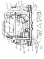
- the presentation of the Fig. 1 shows a profile machining center 10 according to the invention with a turntable unit 12 with a plurality of machining tools 14a, 14b, 14c.
- the processing tools 14a, 14b, 14c are designed as motors and can be provided with different tool inserts.
- a processing unit on the turntable for example, a saw may be provided, alternatively, a saw of the turntable unit 12 may be connected downstream.
- the turntable unit 12 is rotatably supported on a machine frame 16 which rests on a foundation. Means for feeding profiles to the turntable unit 12 and for discharging the processed profiles are not shown for clarity.
- a clamping device of the profile machining center 10 has, see the enlarged view of Fig. 2 , a total of six support rollers 18 with horizontally arranged axis of rotation.
- the axes of rotation of the support rollers 18 are arranged horizontally and fixed relative to the machine frame 16.
- a bearing block 20 which in turn is formed sled-shaped and slidably disposed on a horizontal rail 22.
- a side stop roller 24 is further rotatably arranged, the axis of rotation is arranged vertically.
- first tension rollers 26a, 26b, 26c, 26d, 26e, 26f and four second tension rollers 28a, 28b, 28c are provided with vertically arranged axes of rotation in the profile machining center.
- the first tension rollers 26a to 26f are each displaceable in the horizontal direction and in the vertical direction, the first tension rollers 26a, 26d in the illustration of FIG Fig. 1 and 2 are arranged in front of the turntable 12 and the first tension rollers 26b, 26c, 26e and 26f are arranged behind the turntable 12.
- the first tension rollers 26a, 26d are each disposed on a bearing block 30a, 30b, wherein the bearing blocks, 30a, 30b are each mounted on a carriage, which along a vertically arranged rail 32a, 32b is displaceable.
- the rails 32a, 32b are each disposed on a vertically extending support 34a, 34b, wherein the supports 34a, 34b are in turn connected at their respective lower end to a carriage, which is displaceable along the horizontal rail 22.
- the bearing blocks 30a, 30b can be displaced by means of an adjusting cylinder 36a, 36b along the respective vertical rail 32a, 32b.
- the vertical supports 34a, 34b can each be displaced in the horizontal direction on the rail 22 by means of an adjusting cylinder 38a, 38b.
- the second tension rollers 28a, 28b, 28c, 28d are each mounted on a bearing block 40a, 40b, wherein in the illustrations of the Fig. 1 and 2 only the bearing block 40a can be seen for the tension roller 28a, which in the Fig. 1 and 2 is arranged in front of the turntable 12.
- the bearing block 40a is connected to a carriage, which is arranged displaceably on the horizontally extending rail 22. In order to move the bearing block 40a and thus the second tension roller 28a in the horizontal direction, one in the representations of Fig. 1 and 2 not to be recognized adjusting cylinder provided.
- a profile to be machined is conveyed onto the slewing ring 12 on the support rollers 18 until the point of the profile to be machined is located within the turntable 12.
- the first tensioning rollers 26a to 26f and the second tensioning rollers 28a to 28c are delivered toward the profile, then the profile during machining between the support rollers 18 and the first tension rollers 26a to 26f as well to hold the side stop rollers 24 and the second tension rollers 28a to 28d.
- the adjusting cylinders of the first and second tensioning rollers can be controlled such that either the first and second tensioning rollers are moved into a predefined setpoint position or the first and second tension rollers exert a predefined set tension on the profile.
- the control signals required for this purpose are from an in Fig. 1 and 2 not shown, the control unit can also alternate in time between the different setting modes. For example, a profile is inserted into the processing area within the turntable 12 and then brought into a defined target position against the Soanschlagrollen 24 by moving the second tension rollers 28a to 28d.
- the defined target position of the second tension rollers 28a to 28d can initially be adjusted so that the profile is fixed only in its position, but no appreciable clamping force is applied to the profile. This can be useful, for example, to prevent tilting or turning away the profile during clamping.
- the first tension rollers 26a to 26f are moved against the top of the profile, for example so that the first tension rollers 26a to 26f have a predefined set tension force apply the profile.
- a turning away or tilting of the profile by applying the desired clamping force by means of the first tension rollers 26a to 26f is then prevented by the fact that the profile is already securely fixed between the soanschlagrollen 24 and the second tension rollers 26a-c.
- the control unit can still act on the adjusting cylinders of the second tensioning rollers 28a to 28d so that the second tensioning rollers 28a to 28d apply a predefined set tension force to the profile and thereby the profile immovable for machining by the processing tools 14a, 14b, 14c on the turntable 12 hold.
- first tensioning rollers 26a to 26f and the second tensioning rollers 28a to 28d can each be moved by means of the control unit and the respectively associated adjusting cylinders in such a way that they are either moved into a predefined setpoint position or apply a predefined set clamping force on the profile, wherein the method can be carried out in a predefined set position during a single clamping operation before or after the application of a predefined set clamping force.
- the support rollers 18 define a support plane below the turntable 12 of the profile machining center 10.
- the free space within the turntable 12, which indeed defines the maximum dimensions of a profile to be processed, can be used as far as possible.
- the bearing blocks for the first tensioning rollers 26a to 26f and the bearing blocks 40a, 40b for the second tensioning rollers 28a to 28d are provided with outlet openings for compressed air in order to be able to blow off chips produced during machining from the machined profile.
- the outlet openings are arranged in the bearing blocks so that the compressed air emerges approximately axially to the first tension rollers 26a to 26f and the second tension rollers 28a to 28d.
- the presentation of the Fig. 3 shows the profile processing center 10 of Fig. 1 from the back, so from the Austransportseite a profile.
- a profile to be processed is therefore in the representation of Fig. 1 into the drawing plane and pushed through the turntable 12, in the plane of the Fig. 3 So out of the drawing level.
- first tension rollers 26a, 26b and behind the turntable 12 four first tension rollers 26c, 26d, 26e and 26f are arranged in the direction of movement of a profile to be machined through the turntable 12 before the turntable 12.
- the axes of rotation of the first tension rollers 26a to 26f are each arranged horizontally, and the first tension rollers 26a to 26f are displaceable both in the horizontal and in the vertical direction.
- the first tension rollers 26e, 26f, 26c, 26d arranged in the transport direction of a profile through the turntable 12 behind the turntable 12 are mounted in the same way as the first tension rollers 26a, 26b on a bearing block, which in turn is slidably mounted on a vertical rail.
- the vertical rail is arranged on a vertical support, which in turn is then slidably mounted on a common horizontal rail 44 by means of a carriage.
- the arrangement for the horizontal and vertical displacement of the first tension rollers 26e, 26f, 26c, 26d is the same as already described with reference to FIG Fig. 1 and 2 and the tension rollers 26a, 26b has been explained, so that dispenses with a new discussion.
- Each two first tension rollers 26e, 26f and 26c, 26d are arranged on a common bearing block 46, 48.
- the bearing blocks 46, 48 have an L-like shape, wherein a free leg extends in the direction of the turntable 12 and is arranged horizontally. In the region of the end of this free leg, in each case a first tension roller 26e or 26c is arranged.
- These tensioning rollers 26e, 26c can thereby tension a profile to be machined very close to the machining point in order to enable a high-precision machining.
- Fig. 4 As in the presentation of Fig. 4 can be seen, four support rollers 18 are arranged in the transport direction of a profile to be machined behind the turntable 12 and these four support rollers 18 are together with three soanschlagrollen 24 on a common bearing block 50 arranged.
- the bearing block 50 is slidably mounted on the common horizontal rail 44, wherein a displacement of the bearing block 50 and thus the support rollers 18 and the soanschlagrollen 24 only in the context of adjustments, but not during a tensioning operation.
- the total of six support rollers 18 are seen in the vertical direction, a total of six first tension rollers 26a to 26f opposite.
- the second tension rollers 26a to 26f are arranged so that each first tension roller 26a to 26f in the vertical direction of the support roller 18 is opposite. As a result, symmetrical clamping conditions are ensured even in the vertical direction.
- the first tension rollers 26c, 26d, 26e and 26f are arranged such that the first tension roller 26e is disposed between the two tension rollers 26c, 26d and the first tension roller 26f is then disposed behind the first tension roller 26d is. So if all six tension rollers 26a to 26f rest on top of the top of a profile, so the profile is seen in the direction of transport alternately held by a right and a left-mounted first tension pulley 26a to 26f.
- a clamped profile 60 which rests on the support rollers 18 and which is to be clamped between the Soantschrolle 24 and in the direction of the profile 60 to and away from this second tensioner pulley 28.
- the first tensioning roller 26 can still be moved from above onto the profile 60 toward and away from it.
- the two movable tension rollers 26, 28 are each provided with an actuator, not shown, which has a tension force sensor and a position sensor, wherein the actuators, as already stated, are controlled by a control unit.
- the profile 60 has a square cross-section and is uncritical with respect to the tension exerted by the rollers 18, 24, 26, 28 on the profile 60. It makes sense, the control unit but first the second tension roller 28 to move to the profile 60 until it rests with its back on the soanschlagrolle 24. Subsequently, the first tension roller 26 is delivered to press the profile 60 on the support roller 18. At the same time or subsequently, the actuators of the movable tensioning rollers 26, 28 can be regulated so that they reach an intended set clamping force.
- the second tensioning roller 28 is first moved by the control unit into a predefined setpoint position. In this nominal position, the second tensioning roller provides 28 ensures that the opposite side of the U-profile 70 rests against the side stop roller 24. Since the control unit knows the dimensions of the profile 70 and the side stop roller 24 and the support roller 18 define a zero position, the control unit can determine the desired position. It is essential, however, that the second tension roller 28 is moved in a position control, since no excessive force may be exerted on the U-profile 70.
- the control unit moves the first tension roller 26 on the profile 70 until a predefined set clamping force is reached.
- the first tension roller 26 is operated by means of a clamping force control, since the U-profile 70 is insensitive to a load from above and no major deformations are to be feared.
- the U-profile 70 is thus brought about the second tension roller 28 in the intended position, but only by the first tension roller 26 fixed so that it can be edited.
- the second tensioning pulley 28 can still be moved toward the U-profile 70 by regulating the tensioning force in order to apply a nominal tensioning force also by means of the second tensioning roller 28 , As long as the first tension roller 26 presses the U-profile 70 against the support roller 18, a higher clamping force can be applied to the U-profile 70 by means of the second tension pulley 28 without deformations are to be feared, as if the first tension roller 26, the U Profile 70 would not press against the support roller 18.
- FIG. 3 shows the tensioning of the U-profile 70 according to the prior art.
- Both tension rollers 26, 28 would be delivered in this case only with a clamping force control on the U-profile 70.
- the U-profile 70 would be compressed at the free ends of its legs and could not be edited.
- the prior art has been used to avoid such problems For example, used an intermediate piece, which was inserted into the U-profile 70 to prevent its deformation.
- the presentation of the Fig. 7a schematically shows the tensioning of another, unilaterally open profile 80.
- the cross section of the profile 80 can be described as approximately house-shaped, with a side wall of the house and a roof slope of the gable roof is omitted.
- the profile 80 can be seen against a load from above extremely sensitive to deformation.
- the second tensioning roller 28 is initially moved in the direction of the profile 80 in order to fix the profile 80 between the second tensioning roller 28 and the side stop roller 24.
- the second tension roller 28 can be operated either by means of position control or clamping force control, since the profile 80 relative to a load by the second tension pulley 28 is relatively insensitive.
- the profile 80 is clamped with a predefined set clamping force.
- the first tension roller 26 is moved in the direction of the profile 80, wherein the first tension roller 26 is moved in the position control in a predefined target position.
- This target position is selected so that the first tension roller 26 presses only slightly on the free leg of the profile 80 and this additionally fixed.
- the fact that the first tension roller 26 is moved by means of a position control is not to be feared that the profile 80 is deformed by deficiencies in the clamping force control or by stick-shift effects of the actuator.
- the presentation of the Fig. 7b schematically shows the tensioning of the profile 38 according to the prior art.
- the first tension roller 26 is to move according to the prior art in a clamping force control on the profile 80.
- Stick-shift effects for example, caused by a comparatively high breakaway torque of the actuator of the first tension roller 26, cause the first tension roller 26 presses from above on the profile 80 and this deformed in an inadmissible manner.
- Fig. 8a shows the tensioning of another profile 90 in the profile machining center according to the invention.
- the profile 90 has two strips arranged parallel to one another, which are connected to one another by means of a bevel.
- the profile 90 is thus very difficult to clamp, since it will fall over solely by gravity and thereby, see Fig. 8c , Was arranged in a position in which none of the profile surfaces 90 parallel to the rollers 18, 24, 26, 28 would be arranged. Precise machining would be in the overturned position Fig. 8c impossible to accomplish.
- first the second tension roller 28 is to move in a position control to a designated target position on the profile 90.
- the profile 90 bears on the one hand with its back on the soanschlagrolle 24 and is held by means of the second tension roller 28 which engages the slope of the profile 90, reliably in its upright position. Since the second tensioning roller 28 has been moved to a desired position, there is no fear that the second tensioning roller 28 pushes up the profile 90, so that its in the Fig. 8a Left edge strip no longer horizontally rests on the support roller 18.
- the first tension roller 26 can be placed on the profile 90 to. Also, the first tension roller 26 is thereby moved by means of a position control in a designated target position, so that the profile 90 is not deformed by an excessive clamping force of the first tension roller 26.
- Fig. 8b shows the problems that occur when clamping the profile 90 according to the prior art.
- the second tension roller 28 was delivered to the profile 90 until reaching a predetermined clamping force.
- the profile 90 is pushed up and comes to lie outside the processing area after the feed of the first tensioning roller 26.
- Fig. 8c At first, the first tensioning roller 26 was placed on the profile 90 up to a predetermined tension force. This initially causes the profile 90 to tip over and come to rest on the support roller 18, that none of its surfaces is more parallel to the support roller 18. Although the second tension roller 28 can now be set to, a meaningful processing of the profile 90 is no longer possible in this tilted position.
Landscapes
- Engineering & Computer Science (AREA)
- Mechanical Engineering (AREA)
- Machine Tool Units (AREA)
- Jigs For Machine Tools (AREA)
Description
- Die Erfindung betrifft ein Profilbearbeitungszentrum mit einer Drehkranzeinheit mit mehreren Bearbeitungswerkzeugen und wenigstens einer Spanneinrichtung zum Spannen von Profilen.
- Aus der europäischen Patentschrift
EP 2 070 649 B1 ist ein Profilbearbeitungszentrum mit einer Drehkranzeinheit mit mehreren Bearbeitungswerkzeugen bekannt. Während der Bearbeitung muss ein Profil selbstverständlich mit einer Spanneinrichtung festgehalten werden. - Drehkranzeinheiten ermöglichen zahlreiche unterschiedliche Bearbeitungsvorgänge an einer einzigen Bearbeitungsstation. Die Flexibilität solcher Drehkranzeinheiten wird bei der Profilbearbeitung oft dadurch geschmälert, dass die Profile nicht in jeder beliebigen Lage eingespannt werden können, sondern entweder eine bestimmte Lage einnehmen müssen, in der sie ohne Gefahr von Beschädigungen fest eingespannt werden können oder die Spanneinrichtungen speziell ausgebildet werden müssen, um ein Profil so festzuhalten, dass es einerseits festgehalten wird und andererseits durch die Spannkräfte nicht beschädigt werden kann. Solche spezielle Spanneinrichtungen können beispielsweise speziell gefertigte Formstücke für bestimmte Profile aufweisen. Beson ders kritisch bei der Bearbeitung sind lackierte oder beschichtete Profile oder auch Profile, die frei abragende und gegen Biegung empfindliche Schenkel aufweisen.
- Mit der Erfindung soll ein Profilbearbeitungszentrum mit einer Drehkranzeinheit verbessert werden.
- Erfindungsgemäß ist hierzu ein Profilbearbeitungszentrum mit einer Drehkranzeinheit mit mehreren Bearbeitungswerkzeugen und wenigstens einer Spanneinrichtung zum Spannen von Profilen vorgesehen, wobei ein zu bearbeitendes Profil zur Bearbeitung innerhalb des Drehkranzes angeordnet und mittels der Spanneinrichtung fixiert wird, wobei die Spanneinrichtung wenigstens eine Auflagerolle mit horizontal angeordneter, relativ zum Maschinenrahmen unbeweglicher Drehachse aufweist, bei dem die Spanneinrichtung wenigstens eine erste Spannrolle mit horizontal angeordneter Drehachse und wenigstens eine zweite Spannrolle mit vertikal angeordneter Drehachse aufweist, wobei die erste Spannrolle relativ zum Maschinenrahmen sowohl in horizontaler als auch in vertikaler Richtung verschiebbar ist und die zweite Spannrolle relativ zum Maschinenrahmen wenigstens in horizontaler Richtung verschiebbar ist und wobei die Spanneinrichtung eine Steuereinheit aufweist, um die erste und/oder die zweite Spannrolle wahlweise in eine vordefinierte Sollposition zu verfahren und/oder mittels der ersten und/oder zweiten Spannrolle eine vordefinierte Sollspannkraft auf ein zu bearbeitendes Profil aufzubringen.
- Durch die erfindungsgemäße Ausbildung des Profilbearbeitungszentrums wird es möglich, ein zu bearbeitendes Profil im Wesentlichen in beliebiger Lage und ohne Gefahr von Beschädigungen festzuhalten. Empfindliche Teile von Profilen, beispielsweise frei abragende Schenkel, können mittels der ersten oder der zweiten Spannrolle so gehalten werden, dass die erste und/oder die zweite Spannrolle in eine vordefinierte Sollposition verfahren wird und infolgedessen einen Anschlag für das Profil bildet, ohne eine zu große Spannkraft aufzubringen, die möglicherweise Beschädigungen des Profils hervorrufen könnte. Gleichzeitig kann die jeweils andere Spannrolle oder auch weitere Spannrollen gegen unempfindliche Abschnitte des Profils mit einer vordefinierten Sollspannkraft bewegt werden, um das Profil für die Bearbeitung sicher zu halten. Selbstverständlich ist es auch möglich, in einem ersten Schritt die Spannrollen in eine vordefinierte Sollposition zu verfahren, um das Profil zunächst einmal in seiner Lage zu fixieren. In einem zweiten Schritt kann dann das Spannen erfolgen, indem eine vordefinierte Sollspannkraft aufgebracht wird. Indem die erste Spannrolle relativ zum Maschinenrahmen sowohl in horizontaler als auch in vertikaler Richtung verschiebbar ist und die zweite Spannrolle relativ zum Maschinenrahmen wenigstens in horizontaler Richtung verschiebbar ist, können auch unterschiedlichste Profile für die Bearbeitung sicher gehalten werden. Mit dem erfindungsgemäßen Profilbearbeitungszentrum wird es dadurch möglich, unterschiedlichste Profile in im Wesentlichen beliebiger Lage auf den Auflagerollen sicher festzuhalten und dadurch die Flexibilität der Drehkranzeinheit voll auszunutzen.
- In Weiterbildung der Erfindung definieren die Auflagerollen eine Auflageebene unterhalb einer Drehachse des Drehkranzes.
- Auf diese Weise können auch große Profile problemlos bearbeitet werden und der konstruktiv bei einem Drehkranz begrenzte Innenraum, der für das Durchschieben eines zu bearbeitenden Profils zur Verfügung steht, kann vollständig ausgenutzt werden.
- In Weiterbildung der Erfindung ist wenigstens eine Seitenanschlagrolle mit vertikal angeordneter Drehachse vorgesehen.
- In Weiterbildung der Erfindung weist die wenigstens eine Seitenanschlagrolle eine zum Maschinenrahmen unbewegliche Drehachse auf und definiert eine vertikale Anschlagebene, die in horizontaler Richtung versetzt zur Drehachse des Drehkranzes angeordnet ist.
- Durch Vorsehen einer festen Seitenanschlagrolle wird ein definierter Nullpunkt geschaffen. Durch versetzte Anordnung der durch die Seitenanschlagrolle definierten vertikalen Anschlagebene kann der innerhalb des Drehkranzes zur Verfügung stehende Raum auch für große Profile vollständig genutzt werden.
- In Weiterbildung der Erfindung ist die wenigstens eine Seitenanschlagrolle in horizontaler Richtung verschiebbar.
- Auf diese Weise wird die Flexibilität des erfindungsgemäßen Profilbearbeitungszentrums weiter erhöht, indem beispielsweise für Profile mit großem Querschnitt die vertikale Anschlagebene weiter gegen die Drehachse des Drehkranzes versetzt wird oder umgekehrt für kleine Profile die vertikale Anschlagebene näher an die Drehachse des Drehkranzes herangerückt wird.
- In Weiterbildung der Erfindung sind die Spannrolle und/oder die Seitenanschlagrolle an einem Lagerblock drehbar gelagert, wobei der Lagerblock im Bereich des Außenumfangs der Spannrolle oder Seitenanschlagrolle wenigstens eine Auslassöffnung für Druckluft aufweist.
- Auf diese Weise können bei der Bearbeitung entstehende Abfallspäne leicht und zuverlässig abgeblasen werden. Die Anordnung der Auslassöffnungen für Druckluft im Lagerblock ermöglicht es, die Auslassöffnung sehr nahe an das Werkstück heranzuführen, ohne zusätzlichen Raum in Anspruch zu nehmen.
- In Weiterbildung der Erfindung sind die erste Spannrolle und die zweite Spannrolle mittels jeweils eines Schlittens auf einer horizontal verlaufenden Schiene verschiebbar angeordnet.
- Indem für die erste Spannrolle und die zweite Spannrolle eine gemeinsame horizontal verlaufende Schiene genutzt wird, kann der Raumbedarf und auch der Kostenaufwand für die Spanneinrichtung niedrig gehalten werden.
- In Weiterbildung der Erfindung ist die Seitenanschlagrolle mittels eines Schlittens auf der horizontal verlaufenden Schiene angeordnet.
- Auf diese Weise ist eine sehr präzise Führung der Seitenanschlagrolle möglich.
- In Weiterbildung der Erfindung ist die erste Spannrolle mittels eines Schlittens auf einer vertikal verlaufenden Schiene verschiebbar angeordnet, wobei die vertikal verlaufende Schiene an einem verschiebbar auf der horizontal angeordneten Schiene angeordneten Träger befestigt ist.
- Auf diese Weise wird eine Verschiebung der Spannrolle in zwei Richtungen ermöglicht und dennoch kann eine höchstmögliche Präzision bei der Verschiebung und Zustellung der Spannrolle erreicht werden. Dies ist speziell deshalb sinnvoll, da die Spannrolle ja alternativ in eine vordefinierte Sollposition verfahren werden soll oder eine vordefinierte Sollspannkraft aufbringen soll.
- In Weiterbildung der Erfindung ist in Durchtransportrichtung eines zu bearbeitenden Profils gesehen vor und hinter dem Drehkranz jeweils wenigstens eine horizontal und vertikal verschiebbare erste Spannrolle und jeweils wenigstens eine horizontal verschiebbare Spannrolle mit vertikal angeordneter Drehachse vorgesehen.
- Ein Profil kann auf diese Weise sowohl vor als auch hinter dem Drehkranz zuverlässig gehalten werden. Vorteilhafterweise sind jeweils zwei horizontal und vertikal verschiebbare erste Spannrollen vorgesehen, wobei die beiden Spannrollen an einem sich in Durchtransportrichtung erstreckenden Träger angeordnet sind, der sich in Richtung des Drehkranzes erstreckt. Auf diese Weise können die Führungsschienen für die ersten Spannrollen so weit entfernt von der Ebene des Drehkranzes entfernt werden, dass genügend Platz für die Drehung des Drehkranzes und der auf dem Drehkranz angeordneten Bearbeitungsaggregate zur Verfügung steht. Indem eine der beiden ersten Spannrollen am freien Ende eines Trägers angeordnet ist, der sich in Richtung auf den Drehkranz erstreckt, kann ein zu bearbeitendes Profil dennoch unmittelbar vor und hinter einer Bearbeitungsstelle festgehalten werden.
- In Weiterbildung der Erfindung ist in Durchtransportrichtung eines zu bearbeitenden Profils gesehen rechts und links einer Drehachse des Drehkranzes jeweils wenigstens eine horizontal und vertikal verschiebbare erste Spannrolle mit horizontal angeordneter Drehachse vorgesehen.
- Auf diese Weise können die ersten Spannrollen sowohl von rechts als auch von links an das zu bearbeitende Profil herangefahren werden. Auch bei kompliziert geformten Profilen können in Verbindung mit der erfindungsgemäßen Wahlmöglichkeit, die ersten Spannrollen entweder in eine vordefinierte Sollposition zu verfahren oder mit den Spannrollen eine vordefinierte Sollspannkraft aufzubringen, auch kompliziert geformte und/oder empfindliche Profile zuverlässig für eine hochpräzise Bearbeitung gehalten werden.
- Weitere Merkmale und Vorteile der Erfindung ergeben sich aus den Ansprüchen und der nachfolgenden Beschreibung einer bevorzugten Ausführungsform der Erfindung im Zusammenhang mit den Zeichnungen. In den Zeichnungen zeigen:
- Fig. 1
- eine Ansicht eines erfindungsgemäßen Profilbearbeitungszentrums von der Eintransportseite eines Profils her,
- Fig. 2
- eine abschnittsweise, vergrößerte Darstellung der Ansicht der
Fig. 1 , - Fig. 3
- eine Ansicht des Profilbearbeitungszentrums der
Fig. 1 von der Austransportseite eines Profils her, - Fig. 4
- eine abschnittsweise, vergrößerte Darstellung der Ansicht der
Fig. 3 , - Fig. 5
- eine schematische Darstellung eines Spannvorgangs bei dem erfindungsgemäßen Profilbearbeitungszentrum bei einem Profil mit quadratischem Querschnitt,
- Fig. 6a
- eine schematische Darstellung eines Spannvorgangs bei dem erfindungsgemäßen Profilbearbeitungszentrum bei einem Profil mit U-Querschnitt,
- Fig. 6b
- eine schematische Darstellung eines Spannvorgangs gemäß dem Stand der Technik bei dem Profil aus
Fig. 6a , - Fig. 7a
- eine schematische Darstellung eines Spannvorgangs bei dem erfindungsgemäßen Profilbearbeitungszentrum bei einem Profil mit einseitig offenem, dachförmigen Querschnitt,
- Fig. 7b
- eine schematische Darstellung eines Spannvorgangs gemäß dem Stand der Technik bei dem Profil aus
Fig. 7a , - Fig. 8a
- eine schematische Darstellung eines Spannvorgangs bei einem erfindungsgemäßen Profilbearbeitungszentrum bei einem Profil mit zweifach abgewinkeltem Querschnitt,
- Fig. 8b
- eine schematische Darstellung eines Spannvorgangs gemäß dem Stand der Technik bei dem Profil aus
Fig. 8a und - Fig. 8c
- eine zweite Darstellung eines Spannvorgangs gemäß dem Stand der Technik bei dem Profil aus
Fig. 8a . - Die Darstellung der
Fig. 1 zeigt ein erfindungsgemäßes Profilbearbeitungszentrum 10 mit einer Drehkranzeinheit 12 mit mehreren Bearbeitungswerkzeugen 14a, 14b, 14c. Die Bearbeitungswerkzeuge 14a, 14b, 14c sind als Motoren ausgebildet und können mit unterschiedlichen Werkzeugeinsätzen versehen sein. Als Bearbeitungseinheit auf dem Drehkranz kann beispielsweise auch eine Säge vorgesehen sein, alternativ kann eine Säge der Drehkranzeinheit 12 nachgeschaltet sein. - Die Drehkranzeinheit 12 ist drehbar an einem Maschinenrahmen 16 gelagert, der auf einem Fundament ruht. Einrichtungen zum Zuführen von Profilen zu der Drehkranzeinheit 12 und zum Abführen der bearbeiteten Profile sind der Übersichtlichkeit halber nicht dargestellt.
- Eine Spanneinrichtung des Profilbearbeitungszentrums 10 weist, siehe die vergrößerte Ansicht der
Fig. 2 , insgesamt sechs Auflagerollen 18 mit horizontal angeordneter Drehachse auf. Die Drehachsen der Auflagerollen 18 sind horizontal angeordnet und relativ zum Maschinenrahmen 16 fixiert. Die inFig. 1 und2 im Vordergrund erkennbaren beiden Lagerrollen 18 sind aber an einem Lagerbock 20 drehbar gelagert, der wiederum schlittenförmig ausgebildet ist und auf einer horizontalen Schiene 22 verschiebbar angeordnet ist. Auf dem Lagerbock 2 ist weiter eine Seitenanschlagrolle 24 drehbar angeordnet, deren Drehachse vertikal angeordnet ist. Zusammen mit dem Lagerblock 20 sind somit die beiden inFig. 1 undFig. 2 vor dem Drehkranz 12 angeordneten Lagerrollen 18 in horizontaler Richtung relativ zum Maschinenrahmen 16 verschiebbar, wobei eine solche Verschiebung lediglich im Rahmen von Einstellarbeiten vorgenommen wird. Während der Bearbeitung und speziell während des Spannens eines Profils sind die Auflagerollen 18 und auch die Seitenanschlagrollen 24 relativ zum Maschinenrahmen 16 fixiert. - Die in der Darstellung der
Fig. 1 und2 hinter dem Drehkranz 12 angeordneten Auflagerollen 18 und Seitenanschlagrollen 24 sind ebenfalls an einem gemeinsamen Lagerbock angeordnet, der ebenfalls auf einer horizontal verlaufenden Schiene verschiebbar angeordnet ist, während der Bearbeitung und speziell während des Spannens eines Profils aber relativ zum Maschinenrahmen 16 fixiert ist, wie noch im Zusammenhang mit denFig. 3 und4 erläutert wird. - Neben den Auflagerollen 18 und den Seitenanschlagrollen 24 sind bei dem Profilbearbeitungszentrum 10 sechs erste Spannrollen 26a, 26b, 26c, 26d, 26e, 26f sowie vier zweite Spannrollen 28a, 28b, 28c mit vertikal angeordneten Drehachsen vorgesehen. Die ersten Spannrollen 26a bis 26f sind jeweils in horizontaler Richtung und in vertikaler Richtung verschiebbar, wobei die ersten Spannrollen 26a, 26d in der Darstellung der
Fig. 1 und2 vor dem Drehkranz 12 angeordnet sind und die ersten Spannrollen 26b, 26c, 26e und 26f hinter dem Drehkranz 12 angeordnet sind. - Die ersten Spannrollen 26a, 26d sind jeweils an einem Lagerbock 30a, 30b angeordnet, wobei die Lagerböcke, 30a, 30b jeweils an einem Schlitten befestigt sind, der entlang einer vertikal angeordneten Schiene 32a, 32b verschiebbar ist. Die Schienen 32a, 32b sind jeweils an einem in vertikaler Richtung verlaufenden Träger 34a, 34b angeordnet, wobei die Träger 34a, 34b an ihrem jeweiligen unteren Ende wiederum mit einem Schlitten verbunden sind, der entlang der horizontalen Schiene 22 verschiebbar ist. Die Lagerböcke 30a, 30b können mittels eines Verstellzylinders 36a, 36b entlang der jeweiligen vertikalen Schiene 32a, 32b verschoben werden. Die vertikalen Träger 34a, 34b können jeweils mittels eines Verstellzylinders 38a, 38b in horizontaler Richtung auf der Schiene 22 verschoben werden.
- Die zweiten Spannrollen 28a, 28b, 28c, 28d sind jeweils auf einem Lagerbock 40a, 40b montiert, wobei in den Darstellungen der
Fig. 1 und2 lediglich der Lagerbock 40a für die Spannrolle 28a zu erkennen ist, der in denFig. 1 und2 vor dem Drehkranz 12 angeordnet ist. Der Lagerbock 40a ist mit einem Schlitten verbunden, der auf der horizontal verlaufenden Schiene 22 verschiebbar angeordnet ist. Um den Lagerbock 40a und damit die zweite Spannrolle 28a in horizontaler Richtung zu verschieben, ist ein in den Darstellungen derFig. 1 und2 nicht zu erkennender Verstellzylinder vorgesehen. - Ein zu bearbeitendes Profil wird auf den Auflagerollen 18 liegend auf den Drehkranz 12 zugefördert, bis sich die zu bearbeitende Stelle des Profils innerhalb des Drehkranzes 12 befindet. Um das Profil dann für die Bearbeitung zu fixieren, werden die ersten Spannrollen 26a bis 26f und die zweiten Spannrollen 28a bis 28c in Richtung auf das Profil zugestellt, um dann das Profil während der Bearbeitung zwischen den Auflagerrollen 18 und den ersten Spannrollen 26a bis 26f sowie den Seitenanschlagrollen 24 und den zweiten Spannrollen 28a bis 28d zu halten.
- Erfindungsgemäß können die Verstellzylinder der ersten und zweiten Spannrollen dabei so angesteuert werden, dass entweder die ersten und zweiten Spannrollen in eine vordefinierte Sollposition verfahren werden oder die ersten und zweiten Spannrollen eine vordefinierte Sollspannkraft auf das Profil ausüben. Die hierzu erforderlichen Steuersignale werden von einer in
Fig. 1 und2 nicht dargestellten Steuereinheit ausgegeben, wobei die Steuereinheit auch zeitlich gesehen zwischen den unterschiedlichen Einstellungsmodi abwechseln kann. Beispielsweise wird ein Profil in den Bearbeitungsbereich innerhalb des Drehkranzes 12 eingeschoben und dann durch Verfahren der zweiten Spannrollen 28a bis 28d in eine definierte Sollposition zunächst in Anschlag gegen die Seitenanschlagrollen 24 gebracht. Da die Abmessungen des Profils der Steuereinheit bekannt sind, kann die definierte Sollposition der zweiten Spannrollen 28a bis 28d zunächst so eingestellt werden, dass das Profil nur in seiner Lage fixiert wird, aber noch keine nennenswerte Spannkraft auf das Profil aufgebracht wird. Dies kann sinnvoll sein, um beispielsweise das Kippen oder Wegdrehen des Profils beim Spannen zu verhindern. Nachdem das Profil nun mittels der Auflagerollen 18, der Seitenanschlagrollen 24 und der zweiten Spannrollen 28a bis 28d vorfixiert ist, werden die ersten Spannrollen 26a bis 26f gegen die Oberseite des Profils gefahren, beispielsweise so, dass die ersten Spannrollen 26a bis 26f eine vordefinierte Sollspannkraft auf das Profil aufbringen. Ein Wegdrehen oder Wegkippen des Profils durch das Aufbringen der Sollspannkraft mittels der ersten Spannrollen 26a bis 26f wird dann dadurch verhindert, dass das Profil bereits zwischen den Seitenanschlagrollen 24 und den zweiten Spannrollen 26a bis c sicher fixiert ist. Nachfolgend kann die Steuereinheit noch die Verstellzylinder der zweiten Spannrollen 28a bis 28d so beaufschlagen, dass auch die zweiten Spannrollen 28a bis 28d eine vordefinierte Sollspannkraft auf das Profil aufbringen und dadurch das Profil unverrückbar für die Bearbeitung durch die Bearbeitungswerkzeuge 14a, 14b, 14c an dem Drehkranz 12 festhalten. Wesentlich ist, dass die ersten Spannrollen 26a bis 26f und die zweiten Spannrollen 28a bis 28d jeweils mittels der Steuereinheit und den jeweils zugeordneten Verstellzylindern so verfahren werden können, dass sie entweder in eine vordefinierte Sollposition verfahren werden oder eine vordefinierte Sollspannkraft auf das Profil aufbringen, wobei das Verfahren in eine vordefinierte Sollposition während eines einzigen Spannvorganges vor oder nach dem Aufbringen einer vordefinierten Sollspannkraft erfolgen kann. Mit konventionellen Profilbearbeitungszentren schwierig oder nur unter Verwendung speziell angepasster Formstücke spannbare Profile können dadurch zuverlässig und voll automatisch eingespannt werden. - Anhand der Darstellungen der
Fig. 1 und2 ist zu erkennen, dass die Auflagerollen 18 eine Auflageebene unterhalb des Drehkranzes 12 des Profilbearbeitungszentrums 10 definieren. Der freie Raum innerhalb des Drehkranzes 12, der ja die Maximalabmessungen eines zu bearbeitenden Profiles definiert, kann dadurch weitestgehend genutzt werden. - Die Lagerböcke für die ersten Spannrollen 26a bis 26f und die Lagerböcke 40a, 40b für die zweiten Spannrollen 28a bis 28d sind mit Auslassöffnungen für Druckluft versehen, um bei der Bearbeitung anfallende Späne von dem bearbeiteten Profil abblasen zu können. Die Austrittsöffnungen sind in den Lagerböcken dabei so angeordnet, dass die Druckluft etwa axial zu den ersten Spannrollen 26a bis 26f und den zweiten Spannrollen 28a bis 28d austritt. Indem die Auslassöffnungen in den Lagerböcken angeordnet sind, wird kein zusätzlicher Platz für das Verlegen von Druckluftschläuchen oder dergleichen benötigt. In gleicher Weise können die Lagerböcke 20 für die Auflagerollen 18 und die Seitenanschlagrollen 24 mit Druckluftauslassöffnungen versehen sein.
- Die Darstellung der
Fig. 3 zeigt das Profilbearbeitungszentrum 10 derFig. 1 von hinten, also von der Austransportseite eines Profils. Ein zu bearbeitendes Profil wird demnach in der Darstellung derFig. 1 in die Zeichenebene hinein und durch den Drehkranz 12 hindurchgeschoben, in der Zeichenebene derFig. 3 also aus der Zeichenebene heraus. - Anhand der
Fig. 3 und4 ist zu erkennen, dass in Bewegungsrichtung eines zu bearbeitenden Profils durch den Drehkranz 12 hindurch vor dem Drehkranz 12 zwei erste Spannrollen 26a, 26b und hinter dem Drehkranz 12 vier erste Spannrollen 26c, 26d, 26e und 26f angeordnet sind. Die Drehachsen der erste Spannrollen 26a bis 26f sind jeweils horizontal angeordnet und die ersten Spannrollen 26a bis 26f sind jeweils sowohl in horizontaler als auch in vertikaler Richtung verschiebbar. Die in Durchtransportrichtung eines Profils durch den Drehkranz 12 hinter dem Drehkranz 12 angeordneten ersten Spannrollen 26e, 26f, 26c, 26d sind in gleicher Weise wie die ersten Spannrollen 26a, 26b an einem Lagerbock montiert, der wiederum an einer vertikalen Schiene verschiebbar angeordnet ist. Die vertikale Schiene ist an einem vertikalen Träger angeordnet, der dann wiederum mittels eines Schlittens auf einer gemeinsamen horizontalen Schiene 44 verschiebbar angeordnet ist. Grundsätzlich ist die Anordnung zur horizontalen und vertikalen Verschiebung der ersten Spannrollen 26e, 26f, 26c, 26d gleich wie bereits anhand derFig. 1 und2 und der Spannrollen 26a, 26b erläutert wurde, so dass auf eine erneute Erörterung verzichtet wird. - Jeweils zwei erste Spannrollen 26e, 26f sowie 26c, 26d sind an einem gemeinsamen Lagerbock 46, 48 angeordnet. Die Lagerböcke 46, 48 weisen eine L-artige Form auf, wobei sich ein freier Schenkel in Richtung auf den Drehkranz 12 zu erstreckt und horizontal angeordnet ist. Im Bereich des Endes dieses freien Schenkels ist jeweils eine erste Spannrolle 26e bzw. 26c angeordnet. Diese Spannrollen 26e, 26c können ein zu bearbeitendes Profil dadurch sehr nahe an der Bearbeitungsstelle spannen, um eine hochpräzise Bearbeitung zu ermöglichen.
- Wie in der Darstellung der
Fig. 4 zu erkennen ist, sind vier Auflagerollen 18 in Durchtransportrichtung eines zu bearbeitenden Profils hinter dem Drehkranz 12 angeordnet und diese vier Auflagerrollen 18 sind gemeinsam mit drei Seitenanschlagrollen 24 an einem gemeinsamen Lagerbock 50 angeordnet. Der Lagerbock 50 ist auf der gemeinsamen horizontalen Schiene 44 verschiebbar angeordnet, wobei eine Verschiebung des Lagerbocks 50 und damit der Auflagerollen 18 und der Seitenanschlagrollen 24 nur im Rahmen von Einstellarbeiten, nicht aber während eines Spannvorgangs erfolgt. - Anhand der Darstellung der
Fig. 4 ist zu erkennen, dass insgesamt vier Seitenanschlagrollen 24 vorgesehen sind, denen insgesamt vier, siehe auchFig. 2 , zweite Spannrollen 28a, 28b, 28c und 28d gegenüber liegen. Ein zu bearbeitendes Profil wird beim Spannen dadurch in horizontaler Richtung symmetrisch belastet. - Den insgesamt sechs Auflagerollen 18 liegen in vertikaler Richtung gesehen insgesamt sechs erste Spannrollen 26a bis 26f gegenüber. Die zweiten Spannrollen 26a bis 26f sind dabei so angeordnet, dass jede erste Spannrolle 26a bis 26f in vertikaler Richtung einer der Auflagerolle 18 gegenüberliegt. Dadurch werden auch in vertikaler Richtung symmetrische Einspannverhältnisse sichergestellt.
- In Durchtransportrichtung eines zu bearbeitenden Profils durch den Drehkranz 12 sind die ersten Spannrollen 26c, 26d, 26e und 26f so angeordnet, dass die erste Spannrolle 26e zwischen den beiden Spannrollen 26c, 26d angeordnet ist und die erste Spannrolle 26f dann hinter der ersten Spannrolle 26d angeordnet ist. Wenn also alle sechs Spannrollen 26a bis 26f oben auf der Oberseite eines Profils aufliegen, so wird das Profil in Durchtransportrichtung gesehen abwechselnd von einer rechts und einer links gelagerten ersten Spannrolle 26a bis 26f gehalten. Sollten sich durch die einseitige, fliegende Lagerung der ersten Spannrollen 26a bis 26f leicht unsymmetrische Spannungsverhältnisse ergeben, so werden diese durch die beschriebene abwechselnde, nach Art eines Reißverschlusses ineinandergreifende Anordnung der ersten Spannrollen 26a bis 26f wieder aufgehoben.
- Anhand der Darstellung der
Fig. 5 bis 8c soll das Spannen von Profilen bei dem erfindungsgemäßen Profilbearbeitungszentrum im Vergleich zum Stand der Technik näher erläutert werden. - In der Darstellung der
Fig. 5 ist ein einzuspannendes Profil 60 zu erkennen, das auf den Auflagerrollen 18 aufliegt und das zwischen der Seitenanschlagrolle 24 und der in Richtung auf das Profil 60 zu und von diesem weg verschiebbaren zweiten Spannrolle 28 eingespannt werden soll. Zusätzlich kann noch von oben her die erste Spannrolle 26 auf das Profil 60 zu und von diesem weg bewegt werden. Die beiden beweglichen Spannrollen 26, 28 sind jeweils mit einem nicht dargestellten Aktor versehen, der einen Spannkraftsensor und einen Positionssensor aufweist, wobei die Aktoren, wie bereits ausgeführt, über eine Steuereinheit angesteuert werden. - Das Profil 60 weist einen quadratischen Querschnitt auf und ist in Bezug auf die Spannkraft, die von den Rollen 18, 24, 26, 28 auf das Profil 60 ausgeübt wird, unkritisch. Sinnvollerweise wird die Steuereinheit aber zunächst die zweite Spannrolle 28 auf das Profil 60 zu bewegen, bis dieses mit seiner Rückseite an der Seitenanschlagrolle 24 anliegt. Daraufhin wird die erste Spannrolle 26 zugestellt, um das Profil 60 auf die Auflagerolle 18 zu drücken. Gleichzeitig oder nachfolgend können die Aktoren der beweglichen Spannrollen 26, 28 so geregelt werden, dass sie eine vorgesehene Sollspannkraft erreichen.
- In der Darstellung der
Fig. 6a ist schematisch das Einspannen eines U-förmigen Profils 70 dargestellt, das mit seiner offenen Seite auf den Auflagerollen 18 aufliegt. Mittels der Erfindung wird zum Spannen eines solchen Profils 70, das ersichtlich leicht verformt werden kann, zunächst die zweite Spannrolle 28 mittels der Steuereinheit in eine vordefinierte Sollposition verfahren. In dieser Sollposition sorgt die zweite Spannrolle 28 dafür, dass die gegenüberliegende Seite des U-Profils 70 an der Seitenanschlagrolle 24 anliegt. Da die Steuereinheit die Abmessungen des Profils 70 kennt und die Seitenanschlagrolle 24 und die Auflagerolle 18 eine Nulllage definieren, kann die Steuereinheit die Sollposition bestimmen. Es ist dabei aber wesentlich, dass die zweite Spannrolle 28 in einer Lageregelung verfahren wird, da keine allzu große Kraft auf das U-Profil 70 ausgeübt werden darf. Sobald sich das U-Profil 70 in der inFig. 6a dargestellten Position befindet, bewegt die Steuereinheit die erste Spannrolle 26 auf das Profil 70 zu, bis eine vordefinierte Sollspannkraft erreicht ist. Die erste Spannrolle 26 wird dabei mittels einer Spannkraftregelung betrieben, da das U-Profil 70 gegenüber einer Belastung von oben unempfindlich ist und keine größeren Verformungen zu befürchten sind. Das U-Profil 70 wird somit über die zweite Spannrolle 28 in die vorgesehene Lage gebracht, aber erst durch die erste Spannrolle 26 so fixiert, dass es bearbeitet werden kann. Nachdem die erste Spannrolle 26 das U-Profil 70 fixiert hat, kann, falls erforderlich, die zweite Spannrolle 28 noch über eine Regelung der Spannkraft in Richtung auf das U-Profil 70 zu bewegt werden, um auch mittels der zweiten Spannrolle 28 eine Sollspannkraft aufzubringen. Solange die erste Spannrolle 26 das U-Profil 70 gegen die Auflagerolle 18 drückt, kann auch mittels der zweiten Spannrolle 28 eine höhere Spannkraft auf das U-Profil 70 aufgebracht werden, ohne dass Verformungen zu befürchten sind, als wenn die erste Spannrolle 26 das U-Profil 70 nicht gegen die Auflagerolle 18 drücken würde. - In der
Fig. 6b ist das Spannen des U-Profils 70 nach dem Stand der Technik dargestellt. Beide Spannrollen 26, 28 würden in diesem Fall ausschließlich mit einer Spannkraftreglung auf das U-Profil 70 zugestellt werden. Als logische Folge würde das U-Profil 70 an den freien Enden seiner Schenkel zusammengedrückt und könnte nicht mehr bearbeitet werden. Im Stand der Technik wurde zur Vermeidung solcher Probleme beispielsweise ein Zwischenstück eingesetzt, das in das U-Profil 70 eingesetzt wurde, um dessen Verformung zu verhindern. - Die Darstellung der
Fig. 7a zeigt schematisch das Spannen eines weiteren, einseitig offenen Profils 80. Der Querschnitt des Profils 80 kann als etwa hausförmig beschrieben werden, wobei eine Seitenwand des Hauses sowie eine Dachschräge des Satteldachs weggelassen ist. Das Profil 80 ist ersichtlich gegenüber einer Belastung von oben extrem verformungsempfindlich. - Bei dem erfindungsgemäßen Profilbearbeitungszentrum wird beim Spannen des Profils 80 zunächst die zweite Spannrolle 28 in Richtung auf das Profil 80 zu verfahren, um das Profil 80 zwischen der zweiten Spannrolle 28 und der Seitenanschlagrolle 24 zu fixieren. Die zweite Spannrolle 28 kann dabei entweder mittels Lageregelung oder Spannkraftregelung betrieben werden, da das Profil 80 gegenüber einer Belastung durch die zweite Spannrolle 28 vergleichsweise unempfindlich ist. Beispielsweise wird mittels der zweiten Spannrolle 28 das Profil 80 mit einer vordefinierten Sollspannkraft eingespannt. Nachfolgend wird die erste Spannrolle 26 in Richtung auf das Profil 80 zu bewegt, wobei die erste Spannrolle 26 in der Lageregelung in eine vordefinierte Sollposition verfahren wird. Diese Sollposition ist so gewählt, dass die erste Spannrolle 26 nur leicht auf den freien Schenkel des Profils 80 drückt und dieses dadurch zusätzlich fixiert. Dadurch, dass die erste Spannrolle 26 mittels einer Positionsregelung verfahren wird, ist nicht zu befürchten, dass das Profil 80 durch Unzulänglichkeiten bei der Spannkraftregelung oder auch durch Stick-Shift-Effekte des Aktors verformt wird.
- Die Darstellung der
Fig. 7b zeigt schematisch das Spannen des Profils 38 gemäß dem Stand der Technik. Die erste Spannrolle 26 wird gemäß dem Stand der Technik in einer Spannkraftregelung auf das Profil 80 zu verfahren. Stick-Shift-Effekte, beispielsweise verursacht durch ein vergleichsweise hohes Losbrechmoment des Aktors der ersten Spannrolle 26, führen dazu, dass die erste Spannrolle 26 von oben auf das Profil 80 drückt und dieses dadurch in unzulässiger Weise verformt. - Die Darstellung der
Fig. 8a zeigt das Spannen eines weiteren Profils 90 bei dem erfindungsgemäßen Profilbearbeitungszentrum. Das Profil 90 weist zwei parallel zueinander angeordnete Leisten auf, die mittels einer Schräge miteinander verbunden sind. Das Profil 90 ist dadurch sehr schwierig einzuspannen, da es alleine durch die Schwerkraft umkippen wird und dadurch, sieheFig. 8c , in einer Lage angeordnet wäre, in der keine der Profilflächen 90 parallel zu den Rollen 18, 24, 26, 28 angeordnet wäre. Eine präzise Bearbeitung wäre in der umgekippten Stellung gemäßFig. 8c nicht zu bewerkstelligen. - Bei der Erfindung, siehe
Fig. 8a , wird daher zunächst die zweite Spannrolle 28 in einer Lageregelung bis in eine vorgesehene Sollposition auf das Profil 90 zu verfahren. In dieser Sollposition liegt das Profil 90 einerseits mit seiner Rückseite an der Seitenanschlagrolle 24 an und wird mittels der zweiten Spannrolle 28, die an der Schräge des Profils 90 angreift, zuverlässig in seiner aufrechten Stellung gehalten. Da die zweite Spannrolle 28 in eine Sollposition verfahren wurde, ist nicht zu befürchten, dass die zweite Spannrolle 28 das Profil 90 hoch drückt, so dass dessen in derFig. 8a linker Randstreifen nicht mehr horizontal auf der Auflagerolle 18 aufliegt. Nachdem die zweite Spannrolle 28 in ihre Sollposition verfahren wurde, kann die erste Spannrolle 26 auf das Profil 90 zu gestellt werden. Auch die erste Spannrolle 26 wird dabei mittels einer Lageregelung in eine vorgesehene Sollposition verfahren, so dass das Profil 90 nicht durch eine übermäßige Spannkraft der ersten Spannrolle 26 verformt wird. - Anhand des Spannvorgangs des Profils 90 ist gut zu erkennen, dass es die Erfindung ermöglicht, bisher auch nur mit großem Aufwand zuverlässig einzuspannende Profile ohne zusätzliche Beilagen oder sonstige Maßnahmen einzuspannen.
- Die Darstellung der
Fig. 8b zeigt die Probleme, die beim Einspannen des Profils 90 gemäß dem Stand der Technik auftreten. GemäßFig. 8b wurde zunächst die zweite Spannrolle 28 bis zum Erreichen einer vorgegebenen Spannkraft auf das Profil 90 zugestellt. Dies führt dazu, dass das Profil 90 hoch gedrückt wird und nach dem Zustellen der ersten Spannrolle 26 außerhalb des Bearbeitungsbereichs zu liegen kommt. - Gemäß
Fig. 8c wurde zunächst die erste Spannrolle 26 bis zu einer vorgegebenen Spannkraft auf das Profil 90 zu gestellt. Dies führt zunächst dazu, dass das Profil 90 umkippt und so auf der Auflagerolle 18 zu liegen kommt, dass keine seiner Flächen mehr parallel zu der Auflagerolle 18 ist. Die zweite Spannrolle 28 kann nun zwar zu gestellt werden, eine sinnvolle Bearbeitung des Profils 90 ist in dieser gekippten Lage aber nicht mehr möglich. - Insgesamt wird durch das erfindungsgemäße Profilbearbeitungszentrum 10 eine Möglichkeit geschaffen, auch sehr große Profile in äußerst flexibler Weise und dabei äußerste präzise zu bearbeiten. Dies wird durch die erfindungsgemaße Kombination der Drehkranzeinheit 12 mit einer Spanneinrichtung erreicht, bei der sowohl Spannrollen mit horizontaler als auch vertikaler Drehachse vorgesehen sind und bei der die Spannrollen wahlweise in eine vordefinierte Sollposition verfahren werden können oder eine definierte Sollspannkraft auf ein zu bearbeitendes Profil aufbringen können.
Claims (11)
- Profilbearbeitungszentrum mit einer Drehkranzeinheit (12) mit mehreren Bearbeitungswerkzeugen (14a, 14b, 14c) und wenigstens einer Spanneinrichtung zum Spannen von Profilen, wobei ein zu bearbeitendes Profil zur Bearbeitung innerhalb des Drehkranzes (12) angeordnet und mittels der Spanneinrichtung fixiert werden kann, wobei die Spanneinrichtung wenigstens eine Auflagerolle (18) mit horizontal angeordneter, relativ zum Maschinenrahmen (16) fixierter Drehachse aufweist, dadurch gekennzeichnet, dass die Spanneinrichtung wenigstens eine erste Spannrolle (26a bis 26f) mit horizontal angeordneter Drehachse und wenigstens eine zweite Spannrolle (28a bis 28d) mit vertikal angeordneter Drehachse aufweist, wobei die erste Spannrolle (26a bis 26f) relativ zum Maschinenrahmen (16) sowohl in horizontaler als auch in vertikaler Richtung verschiebbar ist und die zweite Spannrolle (28a bis 28d) relativ zum Maschinenrahmen (16) wenigstens in horizontaler Richtung verschiebbar ist und wobei die Spanneinrichtung eine Steuereinheit aufweist, wobei die Steuereinheit Mittel aufweist, um die erste und/oder die zweite Spannrolle (26a bis 26f, 28a bis 28d) wahlweise in eine vordefinierte Sollposition zu verfahren und wobei die Steuereinheit Mittel aufweist, um wahlweise mittels der ersten und/oder der zweiten Spannrolle eine vordefinierte Sollspannkraft auf ein zu bearbeitendes Profil aufzubringen.
- Profilbearbeitungszentrum nach Anspruch 1, dadurch gekennzeichnet, dass die Auflagerollen (18) eine Auflageebene unterhalb einer Drehachse des Drehkranzes (12) definieren.
- Profilbearbeitungszentrum nach Anspruch 1 oder 2, dadurch gekennzeichnet, dass wenigstens eine Seitenanschlagrolle (24) mit vertikal angeordneter Drehachse vorgesehen ist.
- Profilbearbeitungszentrum nach Anspruch 3, dadurch gekennzeichnet, dass die wenigstens eine Seitenanschlagrolle (24) eine relativ zum Maschinenrahmen (16) fixierte Drehachse aufweist und eine vertikale Anschlagebene definiert, die in horizontaler Richtung versetzt zur Drehachse des Drehkranzes (12) angeordnet ist.
- Profilbearbeitungszentrum nach Anspruch 3, dadurch gekennzeichnet, dass die wenigstens eine Seitenanschlagrolle (24) in horizontaler Richtung verschiebbar ist.
- Profilbearbeitungszentrum nach einem der vorstehenden Ansprüche, dadurch gekennzeichnet, dass die Spannrolle (26a bis 26f, 28a bis 28d), die Auflagerolle (18) und/oder die Seitenanschlagrolle (24) an einem Lagerblock (30a, 30b, 40a, 40b) drehbar gelagert ist, wobei der Lagerblock im Bereich des Außenumfangs der Spannrolle (26a bis 26f, 28a bis 28d), Auflagerolle (18) und/oder Seitenanschlagrolle (24) wenigstens eine Auslassöffnung für Druckluft aufweist.
- Profilbearbeitungszentrum nach wenigstens einem der vorstehenden Ansprüche, dadurch gekennzeichnet, dass die erste Spannrolle (26a bis 26f) und die zweite Spannrolle (28a bis 28d) mittels jeweils eines Schlittens auf einer horizontal verlaufende Schiene (22, 44) verschiebbar angeordnet sind.
- Profilbearbeitungszentrum nach Anspruch 7, dadurch gekennzeichnet, dass die Seitenanschlagrolle (24) und/oder die Auflagerolle (18) mittels eines Schlittens auf der horizontal verlaufenden Schiene angeordnet ist.
- Profilbearbeitungszentrum nach Anspruch 7 oder 8, dadurch gekennzeichnet, dass die erste Spannrolle (26a bis 26f) mittels eines Schlittens auf einer vertikal verlaufenden Schiene (32a, 32b) verschiebbar angeordnet ist, wobei die vertikal verlaufende Schiene (32a, 32b) an einem verschiebbar auf der horizontal angeordneten Schiene (22, 44) angeordneten Träger (34a, 34b) befestigt ist.
- Profilbearbeitungszentrum nach wenigstens einem der vorstehenden Ansprüche, dadurch gekennzeichnet, dass in Durchtransportrichtung eines zu bearbeitenden Profils gesehen vor und hinter dem Drehkranz (12) jeweils wenigstens eine horizontal und vertikal verschiebbare erste Spannrolle (26a bis 26f) und jeweils wenigstens eine horizontal verschiebbare zweite Spannrolle (28a bis 28d) mit vertikal angeordneter Drehachse vorgesehen ist.
- Profilbearbeitungszentrum nach einem der vorstehenden Ansprüche, dadurch gekennzeichnet, dass in Durchtransportrichtung eines zu bearbeitenden Profils gesehen rechts und links einer Drehachse des Drehkranzes (12) jeweils wenigstens eine horizontal und vertikal verschiebbare erste Spannrolle (26a bis 26f) mit horizontal angeordneter Drehachse vorgesehen ist.
Applications Claiming Priority (1)
| Application Number | Priority Date | Filing Date | Title |
|---|---|---|---|
| DE201010014376 DE102010014376B4 (de) | 2010-03-31 | 2010-03-31 | Profilbearbeitungseinrichtung |
Publications (2)
| Publication Number | Publication Date |
|---|---|
| EP2371480A1 EP2371480A1 (de) | 2011-10-05 |
| EP2371480B1 true EP2371480B1 (de) | 2012-09-26 |
Family
ID=44148510
Family Applications (1)
| Application Number | Title | Priority Date | Filing Date |
|---|---|---|---|
| EP20110153248 Active EP2371480B1 (de) | 2010-03-31 | 2011-02-03 | Profilbearbeitungszentrum |
Country Status (2)
| Country | Link |
|---|---|
| EP (1) | EP2371480B1 (de) |
| DE (1) | DE102010014376B4 (de) |
Families Citing this family (3)
| Publication number | Priority date | Publication date | Assignee | Title |
|---|---|---|---|---|
| CN105563122A (zh) * | 2016-02-04 | 2016-05-11 | 江门银特银数控机床有限公司 | 一种型材加工中心 |
| WO2019240680A2 (en) * | 2018-03-05 | 2019-12-19 | Kaban Makina Sanayi Ve Ticaret Limited Sirketi | A section handling machine with rotary mechanism |
| CN110026894A (zh) * | 2019-04-10 | 2019-07-19 | 佛山市镭科智能设备有限公司 | 一种型材夹紧装置 |
Family Cites Families (2)
| Publication number | Priority date | Publication date | Assignee | Title |
|---|---|---|---|---|
| DE3510381C2 (de) * | 1985-03-22 | 1989-10-12 | Oxytechnik Gesellschaft für Systemtechnik mbH, 6236 Eschborn | Vorrichtung und Verfahren zum Bearbeiten von Werkstücken, insbesondere zum thermischen Trennen von Profilen |
| DE102007060586B4 (de) | 2007-12-13 | 2020-11-26 | Thorwesten Maschinenbau Gmbh | Vorrichtung zur Bearbeitung von Profilen |
-
2010
- 2010-03-31 DE DE201010014376 patent/DE102010014376B4/de active Active
-
2011
- 2011-02-03 EP EP20110153248 patent/EP2371480B1/de active Active
Also Published As
| Publication number | Publication date |
|---|---|
| DE102010014376A1 (de) | 2011-10-06 |
| EP2371480A1 (de) | 2011-10-05 |
| DE102010014376B4 (de) | 2012-05-03 |
Similar Documents
| Publication | Publication Date | Title |
|---|---|---|
| EP3052256B1 (de) | Biegepresse und biegeverfahren | |
| DE102018008199A1 (de) | Verfahren zum Bearbeiten von länglichen Werkstücken aus Holz, Kunststoff und dergleichen sowie Maschine zur Durchführung des Verfahrens | |
| DE4314641C2 (de) | Spannrahmen für Tiefziehmaschinen | |
| DE4019285A1 (de) | Spanneinrichtung zum gezielten spannen von werkstuecken | |
| DE102007060586A1 (de) | Vorrichtung zur Bearbeitung von Profilen | |
| DE4040167C2 (de) | Anlage zum kontinuierlichen Schneiden von Kunststoffblöcken | |
| DE102018113978B3 (de) | Kaltwalzmaschine und Verfahren zur Erzeugung eines Profils an einem Werkstück | |
| EP2371480B1 (de) | Profilbearbeitungszentrum | |
| DE202009008404U1 (de) | Sägemodul für die Bearbeitung von Fenster- und Fassadenprofilen | |
| EP2926942B1 (de) | Profilbearbeitungsvorrichtung und verfahren zum bearbeiten von profilen | |
| DE2845052A1 (de) | Geruestwechselvorrichtung | |
| EP2475474B1 (de) | Biegemaschine zum biegen von länglichen werkstücken, insbesondere von rohren bzw. profilen | |
| DE19508864C1 (de) | Maschine zum Ummanteln von länglichen Werkstücken | |
| DE3120331A1 (de) | Bohr- und/oder fraesvorrichtung | |
| EP0292864B1 (de) | Holzbearbeitungsmaschine | |
| EP0894555A2 (de) | Profilrollmaschine mit Kraftrahmen | |
| DE102019003613A1 (de) | Verfahren zur Bearbeitung von Werkstücken aus Holz, Kunststoff und dergleichen | |
| EP1764177B1 (de) | Ablängvorrichtung für Glasleisten oder entsprechende Stabprofile und Verfahren zum Ablängen von Glasleisten oder entsprechenden Stabprofilen | |
| DE602004001523T2 (de) | Werkzeugmaschine | |
| EP3275609A1 (de) | Anlage und verfahren zum bearbeiten von werkstücken aus holz, kunststoff und dergleichen | |
| DE10024926C2 (de) | Ummantelungsmaschine mit am Maschinengestell lösbaren Halteringen | |
| DE19517887C2 (de) | Maschine zum Einarbeiten von Ausnehmungen in zwei gegenüberliegende Längsseiten eines länglichen Werkstückes, insbesondere eines Rahmenholzes | |
| DE19721521C2 (de) | Numerisch gesteuerte Zapfenschneidmaschine | |
| EP0624441B1 (de) | Rahmenpresse | |
| DE10303136B3 (de) | Band- und Platinenabstützung für ein Schneidwerkzeug mit zwei Schneidbalken |
Legal Events
| Date | Code | Title | Description |
|---|---|---|---|
| PUAI | Public reference made under article 153(3) epc to a published international application that has entered the european phase |
Free format text: ORIGINAL CODE: 0009012 |
|
| AK | Designated contracting states |
Kind code of ref document: A1 Designated state(s): AL AT BE BG CH CY CZ DE DK EE ES FI FR GB GR HR HU IE IS IT LI LT LU LV MC MK MT NL NO PL PT RO RS SE SI SK SM TR |
|
| AX | Request for extension of the european patent |
Extension state: BA ME |
|
| 17P | Request for examination filed |
Effective date: 20111007 |
|
| 17Q | First examination report despatched |
Effective date: 20120404 |
|
| GRAP | Despatch of communication of intention to grant a patent |
Free format text: ORIGINAL CODE: EPIDOSNIGR1 |
|
| 17Q | First examination report despatched |
Effective date: 20120404 |
|
| GRAS | Grant fee paid |
Free format text: ORIGINAL CODE: EPIDOSNIGR3 |
|
| GRAA | (expected) grant |
Free format text: ORIGINAL CODE: 0009210 |
|
| AK | Designated contracting states |
Kind code of ref document: B1 Designated state(s): AL AT BE BG CH CY CZ DE DK EE ES FI FR GB GR HR HU IE IS IT LI LT LU LV MC MK MT NL NO PL PT RO RS SE SI SK SM TR |
|
| REG | Reference to a national code |
Ref country code: GB Ref legal event code: FG4D Free format text: NOT ENGLISH |
|
| REG | Reference to a national code |
Ref country code: CH Ref legal event code: EP |
|
| REG | Reference to a national code |
Ref country code: AT Ref legal event code: REF Ref document number: 576792 Country of ref document: AT Kind code of ref document: T Effective date: 20121015 |
|
| REG | Reference to a national code |
Ref country code: IE Ref legal event code: FG4D Free format text: LANGUAGE OF EP DOCUMENT: GERMAN |
|
| REG | Reference to a national code |
Ref country code: DE Ref legal event code: R096 Ref document number: 502011000119 Country of ref document: DE Effective date: 20121115 |
|
| PG25 | Lapsed in a contracting state [announced via postgrant information from national office to epo] |
Ref country code: HR Free format text: LAPSE BECAUSE OF FAILURE TO SUBMIT A TRANSLATION OF THE DESCRIPTION OR TO PAY THE FEE WITHIN THE PRESCRIBED TIME-LIMIT Effective date: 20120926 Ref country code: LT Free format text: LAPSE BECAUSE OF FAILURE TO SUBMIT A TRANSLATION OF THE DESCRIPTION OR TO PAY THE FEE WITHIN THE PRESCRIBED TIME-LIMIT Effective date: 20120926 Ref country code: NO Free format text: LAPSE BECAUSE OF FAILURE TO SUBMIT A TRANSLATION OF THE DESCRIPTION OR TO PAY THE FEE WITHIN THE PRESCRIBED TIME-LIMIT Effective date: 20121226 Ref country code: FI Free format text: LAPSE BECAUSE OF FAILURE TO SUBMIT A TRANSLATION OF THE DESCRIPTION OR TO PAY THE FEE WITHIN THE PRESCRIBED TIME-LIMIT Effective date: 20120926 |
|
| REG | Reference to a national code |
Ref country code: LT Ref legal event code: MG4D Effective date: 20120926 |
|
| REG | Reference to a national code |
Ref country code: NL Ref legal event code: VDEP Effective date: 20120926 |
|
| PG25 | Lapsed in a contracting state [announced via postgrant information from national office to epo] |
Ref country code: GR Free format text: LAPSE BECAUSE OF FAILURE TO SUBMIT A TRANSLATION OF THE DESCRIPTION OR TO PAY THE FEE WITHIN THE PRESCRIBED TIME-LIMIT Effective date: 20121227 Ref country code: SE Free format text: LAPSE BECAUSE OF FAILURE TO SUBMIT A TRANSLATION OF THE DESCRIPTION OR TO PAY THE FEE WITHIN THE PRESCRIBED TIME-LIMIT Effective date: 20120926 Ref country code: SI Free format text: LAPSE BECAUSE OF FAILURE TO SUBMIT A TRANSLATION OF THE DESCRIPTION OR TO PAY THE FEE WITHIN THE PRESCRIBED TIME-LIMIT Effective date: 20120926 Ref country code: LV Free format text: LAPSE BECAUSE OF FAILURE TO SUBMIT A TRANSLATION OF THE DESCRIPTION OR TO PAY THE FEE WITHIN THE PRESCRIBED TIME-LIMIT Effective date: 20120926 |
|
| PG25 | Lapsed in a contracting state [announced via postgrant information from national office to epo] |
Ref country code: NL Free format text: LAPSE BECAUSE OF FAILURE TO SUBMIT A TRANSLATION OF THE DESCRIPTION OR TO PAY THE FEE WITHIN THE PRESCRIBED TIME-LIMIT Effective date: 20120926 Ref country code: CZ Free format text: LAPSE BECAUSE OF FAILURE TO SUBMIT A TRANSLATION OF THE DESCRIPTION OR TO PAY THE FEE WITHIN THE PRESCRIBED TIME-LIMIT Effective date: 20120926 Ref country code: EE Free format text: LAPSE BECAUSE OF FAILURE TO SUBMIT A TRANSLATION OF THE DESCRIPTION OR TO PAY THE FEE WITHIN THE PRESCRIBED TIME-LIMIT Effective date: 20120926 Ref country code: RO Free format text: LAPSE BECAUSE OF FAILURE TO SUBMIT A TRANSLATION OF THE DESCRIPTION OR TO PAY THE FEE WITHIN THE PRESCRIBED TIME-LIMIT Effective date: 20120926 Ref country code: IS Free format text: LAPSE BECAUSE OF FAILURE TO SUBMIT A TRANSLATION OF THE DESCRIPTION OR TO PAY THE FEE WITHIN THE PRESCRIBED TIME-LIMIT Effective date: 20130126 |
|
| PG25 | Lapsed in a contracting state [announced via postgrant information from national office to epo] |
Ref country code: PL Free format text: LAPSE BECAUSE OF FAILURE TO SUBMIT A TRANSLATION OF THE DESCRIPTION OR TO PAY THE FEE WITHIN THE PRESCRIBED TIME-LIMIT Effective date: 20120926 Ref country code: SK Free format text: LAPSE BECAUSE OF FAILURE TO SUBMIT A TRANSLATION OF THE DESCRIPTION OR TO PAY THE FEE WITHIN THE PRESCRIBED TIME-LIMIT Effective date: 20120926 Ref country code: PT Free format text: LAPSE BECAUSE OF FAILURE TO SUBMIT A TRANSLATION OF THE DESCRIPTION OR TO PAY THE FEE WITHIN THE PRESCRIBED TIME-LIMIT Effective date: 20130128 |
|
| PG25 | Lapsed in a contracting state [announced via postgrant information from national office to epo] |
Ref country code: DK Free format text: LAPSE BECAUSE OF FAILURE TO SUBMIT A TRANSLATION OF THE DESCRIPTION OR TO PAY THE FEE WITHIN THE PRESCRIBED TIME-LIMIT Effective date: 20120926 Ref country code: RS Free format text: LAPSE BECAUSE OF FAILURE TO SUBMIT A TRANSLATION OF THE DESCRIPTION OR TO PAY THE FEE WITHIN THE PRESCRIBED TIME-LIMIT Effective date: 20120926 Ref country code: BG Free format text: LAPSE BECAUSE OF FAILURE TO SUBMIT A TRANSLATION OF THE DESCRIPTION OR TO PAY THE FEE WITHIN THE PRESCRIBED TIME-LIMIT Effective date: 20121226 |
|
| PLBE | No opposition filed within time limit |
Free format text: ORIGINAL CODE: 0009261 |
|
| STAA | Information on the status of an ep patent application or granted ep patent |
Free format text: STATUS: NO OPPOSITION FILED WITHIN TIME LIMIT |
|
| BERE | Be: lapsed |
Owner name: ELUMATEC G.M.B.H. Effective date: 20130228 |
|
| 26N | No opposition filed |
Effective date: 20130627 |
|
| PG25 | Lapsed in a contracting state [announced via postgrant information from national office to epo] |
Ref country code: MC Free format text: LAPSE BECAUSE OF NON-PAYMENT OF DUE FEES Effective date: 20130228 |
|
| REG | Reference to a national code |
Ref country code: DE Ref legal event code: R097 Ref document number: 502011000119 Country of ref document: DE Effective date: 20130627 |
|
| PG25 | Lapsed in a contracting state [announced via postgrant information from national office to epo] |
Ref country code: ES Free format text: LAPSE BECAUSE OF FAILURE TO SUBMIT A TRANSLATION OF THE DESCRIPTION OR TO PAY THE FEE WITHIN THE PRESCRIBED TIME-LIMIT Effective date: 20130106 |
|
| PG25 | Lapsed in a contracting state [announced via postgrant information from national office to epo] |
Ref country code: CY Free format text: LAPSE BECAUSE OF FAILURE TO SUBMIT A TRANSLATION OF THE DESCRIPTION OR TO PAY THE FEE WITHIN THE PRESCRIBED TIME-LIMIT Effective date: 20120926 |
|
| REG | Reference to a national code |
Ref country code: IE Ref legal event code: MM4A |
|
| PG25 | Lapsed in a contracting state [announced via postgrant information from national office to epo] |
Ref country code: AL Free format text: LAPSE BECAUSE OF FAILURE TO SUBMIT A TRANSLATION OF THE DESCRIPTION OR TO PAY THE FEE WITHIN THE PRESCRIBED TIME-LIMIT Effective date: 20120926 Ref country code: IE Free format text: LAPSE BECAUSE OF NON-PAYMENT OF DUE FEES Effective date: 20130203 Ref country code: BE Free format text: LAPSE BECAUSE OF NON-PAYMENT OF DUE FEES Effective date: 20130228 |
|
| PG25 | Lapsed in a contracting state [announced via postgrant information from national office to epo] |
Ref country code: MT Free format text: LAPSE BECAUSE OF FAILURE TO SUBMIT A TRANSLATION OF THE DESCRIPTION OR TO PAY THE FEE WITHIN THE PRESCRIBED TIME-LIMIT Effective date: 20120926 |
|
| REG | Reference to a national code |
Ref country code: CH Ref legal event code: PL |
|
| PG25 | Lapsed in a contracting state [announced via postgrant information from national office to epo] |
Ref country code: CH Free format text: LAPSE BECAUSE OF NON-PAYMENT OF DUE FEES Effective date: 20140228 Ref country code: LI Free format text: LAPSE BECAUSE OF NON-PAYMENT OF DUE FEES Effective date: 20140228 |
|
| PG25 | Lapsed in a contracting state [announced via postgrant information from national office to epo] |
Ref country code: SM Free format text: LAPSE BECAUSE OF FAILURE TO SUBMIT A TRANSLATION OF THE DESCRIPTION OR TO PAY THE FEE WITHIN THE PRESCRIBED TIME-LIMIT Effective date: 20120926 |
|
| PG25 | Lapsed in a contracting state [announced via postgrant information from national office to epo] |
Ref country code: HU Free format text: LAPSE BECAUSE OF FAILURE TO SUBMIT A TRANSLATION OF THE DESCRIPTION OR TO PAY THE FEE WITHIN THE PRESCRIBED TIME-LIMIT; INVALID AB INITIO Effective date: 20110203 Ref country code: LU Free format text: LAPSE BECAUSE OF NON-PAYMENT OF DUE FEES Effective date: 20130203 Ref country code: MK Free format text: LAPSE BECAUSE OF FAILURE TO SUBMIT A TRANSLATION OF THE DESCRIPTION OR TO PAY THE FEE WITHIN THE PRESCRIBED TIME-LIMIT Effective date: 20120926 |
|
| REG | Reference to a national code |
Ref country code: FR Ref legal event code: PLFP Year of fee payment: 6 |
|
| REG | Reference to a national code |
Ref country code: FR Ref legal event code: PLFP Year of fee payment: 7 |
|
| REG | Reference to a national code |
Ref country code: FR Ref legal event code: PLFP Year of fee payment: 8 |
|
| REG | Reference to a national code |
Ref country code: DE Ref legal event code: R082 Ref document number: 502011000119 Country of ref document: DE Representative=s name: PATENTANWAELTE RUFF, WILHELM, BEIER, DAUSTER &, DE Ref country code: DE Ref legal event code: R081 Ref document number: 502011000119 Country of ref document: DE Owner name: ELUMATEC AG, DE Free format text: FORMER OWNER: ELUMATEC GMBH, 75417 MUEHLACKER, DE |
|
| PGFP | Annual fee paid to national office [announced via postgrant information from national office to epo] |
Ref country code: AT Payment date: 20230215 Year of fee payment: 13 |
|
| P01 | Opt-out of the competence of the unified patent court (upc) registered |
Effective date: 20230525 |
|
| REG | Reference to a national code |
Ref country code: AT Ref legal event code: MM01 Ref document number: 576792 Country of ref document: AT Kind code of ref document: T Effective date: 20240203 |
|
| PG25 | Lapsed in a contracting state [announced via postgrant information from national office to epo] |
Ref country code: AT Free format text: LAPSE BECAUSE OF NON-PAYMENT OF DUE FEES Effective date: 20240203 |
|
| PG25 | Lapsed in a contracting state [announced via postgrant information from national office to epo] |
Ref country code: AT Free format text: LAPSE BECAUSE OF NON-PAYMENT OF DUE FEES Effective date: 20240203 |
|
| PGFP | Annual fee paid to national office [announced via postgrant information from national office to epo] |
Ref country code: DE Payment date: 20250219 Year of fee payment: 15 |
|
| PGFP | Annual fee paid to national office [announced via postgrant information from national office to epo] |
Ref country code: FR Payment date: 20250219 Year of fee payment: 15 |
|
| PGFP | Annual fee paid to national office [announced via postgrant information from national office to epo] |
Ref country code: IT Payment date: 20250228 Year of fee payment: 15 Ref country code: GB Payment date: 20250220 Year of fee payment: 15 |
|
| PGFP | Annual fee paid to national office [announced via postgrant information from national office to epo] |
Ref country code: TR Payment date: 20250128 Year of fee payment: 15 |