EP2926942B1 - Profilbearbeitungsvorrichtung und verfahren zum bearbeiten von profilen - Google Patents
Profilbearbeitungsvorrichtung und verfahren zum bearbeiten von profilen Download PDFInfo
- Publication number
- EP2926942B1 EP2926942B1 EP15159239.1A EP15159239A EP2926942B1 EP 2926942 B1 EP2926942 B1 EP 2926942B1 EP 15159239 A EP15159239 A EP 15159239A EP 2926942 B1 EP2926942 B1 EP 2926942B1
- Authority
- EP
- European Patent Office
- Prior art keywords
- profile
- tool
- gripper
- machining
- roller
- Prior art date
- Legal status (The legal status is an assumption and is not a legal conclusion. Google has not performed a legal analysis and makes no representation as to the accuracy of the status listed.)
- Active
Links
- 238000003754 machining Methods 0.000 title claims description 42
- 238000000034 method Methods 0.000 title claims description 9
- 238000011161 development Methods 0.000 description 8
- 230000018109 developmental process Effects 0.000 description 8
- 238000005520 cutting process Methods 0.000 description 6
- 239000000463 material Substances 0.000 description 4
- 239000002184 metal Substances 0.000 description 3
- 238000006073 displacement reaction Methods 0.000 description 1
- 238000005553 drilling Methods 0.000 description 1
- 230000000694 effects Effects 0.000 description 1
- 238000004519 manufacturing process Methods 0.000 description 1
- 238000003801 milling Methods 0.000 description 1
- 230000000284 resting effect Effects 0.000 description 1
- 238000003860 storage Methods 0.000 description 1
Images


Classifications
-
- B—PERFORMING OPERATIONS; TRANSPORTING
- B23—MACHINE TOOLS; METAL-WORKING NOT OTHERWISE PROVIDED FOR
- B23Q—DETAILS, COMPONENTS, OR ACCESSORIES FOR MACHINE TOOLS, e.g. ARRANGEMENTS FOR COPYING OR CONTROLLING; MACHINE TOOLS IN GENERAL CHARACTERISED BY THE CONSTRUCTION OF PARTICULAR DETAILS OR COMPONENTS; COMBINATIONS OR ASSOCIATIONS OF METAL-WORKING MACHINES, NOT DIRECTED TO A PARTICULAR RESULT
- B23Q3/00—Devices holding, supporting, or positioning work or tools, of a kind normally removable from the machine
- B23Q3/02—Devices holding, supporting, or positioning work or tools, of a kind normally removable from the machine for mounting on a work-table, tool-slide, or analogous part
- B23Q3/06—Work-clamping means
- B23Q3/069—Work-clamping means for pressing workpieces against a work-table
-
- B—PERFORMING OPERATIONS; TRANSPORTING
- B23—MACHINE TOOLS; METAL-WORKING NOT OTHERWISE PROVIDED FOR
- B23D—PLANING; SLOTTING; SHEARING; BROACHING; SAWING; FILING; SCRAPING; LIKE OPERATIONS FOR WORKING METAL BY REMOVING MATERIAL, NOT OTHERWISE PROVIDED FOR
- B23D47/00—Sawing machines or sawing devices working with circular saw blades, characterised only by constructional features of particular parts
- B23D47/04—Sawing machines or sawing devices working with circular saw blades, characterised only by constructional features of particular parts of devices for feeding, positioning, clamping, or rotating work
-
- B—PERFORMING OPERATIONS; TRANSPORTING
- B23—MACHINE TOOLS; METAL-WORKING NOT OTHERWISE PROVIDED FOR
- B23Q—DETAILS, COMPONENTS, OR ACCESSORIES FOR MACHINE TOOLS, e.g. ARRANGEMENTS FOR COPYING OR CONTROLLING; MACHINE TOOLS IN GENERAL CHARACTERISED BY THE CONSTRUCTION OF PARTICULAR DETAILS OR COMPONENTS; COMBINATIONS OR ASSOCIATIONS OF METAL-WORKING MACHINES, NOT DIRECTED TO A PARTICULAR RESULT
- B23Q7/00—Arrangements for handling work specially combined with or arranged in, or specially adapted for use in connection with, machine tools, e.g. for conveying, loading, positioning, discharging, sorting
- B23Q7/04—Arrangements for handling work specially combined with or arranged in, or specially adapted for use in connection with, machine tools, e.g. for conveying, loading, positioning, discharging, sorting by means of grippers
-
- B—PERFORMING OPERATIONS; TRANSPORTING
- B23—MACHINE TOOLS; METAL-WORKING NOT OTHERWISE PROVIDED FOR
- B23Q—DETAILS, COMPONENTS, OR ACCESSORIES FOR MACHINE TOOLS, e.g. ARRANGEMENTS FOR COPYING OR CONTROLLING; MACHINE TOOLS IN GENERAL CHARACTERISED BY THE CONSTRUCTION OF PARTICULAR DETAILS OR COMPONENTS; COMBINATIONS OR ASSOCIATIONS OF METAL-WORKING MACHINES, NOT DIRECTED TO A PARTICULAR RESULT
- B23Q7/00—Arrangements for handling work specially combined with or arranged in, or specially adapted for use in connection with, machine tools, e.g. for conveying, loading, positioning, discharging, sorting
- B23Q7/05—Arrangements for handling work specially combined with or arranged in, or specially adapted for use in connection with, machine tools, e.g. for conveying, loading, positioning, discharging, sorting by means of roller-ways
-
- B—PERFORMING OPERATIONS; TRANSPORTING
- B23—MACHINE TOOLS; METAL-WORKING NOT OTHERWISE PROVIDED FOR
- B23Q—DETAILS, COMPONENTS, OR ACCESSORIES FOR MACHINE TOOLS, e.g. ARRANGEMENTS FOR COPYING OR CONTROLLING; MACHINE TOOLS IN GENERAL CHARACTERISED BY THE CONSTRUCTION OF PARTICULAR DETAILS OR COMPONENTS; COMBINATIONS OR ASSOCIATIONS OF METAL-WORKING MACHINES, NOT DIRECTED TO A PARTICULAR RESULT
- B23Q2240/00—Machine tools specially suited for a specific kind of workpiece
- B23Q2240/007—Elongated workpieces
Definitions
- the invention relates to a profile machining device with a machine frame, at least one tool for profile machining, at least one clamping device for a profile to be machined and a feed device for moving a profile to be processed in a transport direction by the profile processing device, wherein the transport direction corresponds to a longitudinal direction of the profile and wherein the Clamping device has at least one roller tensioner for guiding the profile during a profile machining with simultaneous movement of the profile by means of the feed device.
- the invention also relates to a method for processing profiles with a profile-machining device according to the invention.
- the device comprises a machine frame, on which the plate stack rests, and a tool designed as a circular saw, which is fastened to a portal.
- the gantry is slidable along guide rails that run on either side of the plate stack.
- the tool is displaceable transversely to the guide rails on the portal.
- To the left and right of the circular saw blade rollers are arranged on the tool carrier, which can be pressed onto the plate stack during the machining process. The rollers are moved together with the tool carrier and thus together with the circular saw blade. Movement of the plate stack relative to the machine frame during processing of the plate stack is not provided.
- a processing device for plate material is provided.
- a tool such as a router, is attached to a tool carrier that can be moved relative to the plate material to be processed.
- the tool carrier is provided with pressure rollers.
- the pressure rollers are connected to a feed device for the tool, so that the clamping can always be done by means of the pressure rollers in the region of the tool, even if the tool changes its position in the course of processing.
- a device for processing stacked plate material is known. Specifically, it is provided to process a stack of sheet metal plates with a cutting torch.
- the cutting torch is arranged on a portal, which can be moved in and against the longitudinal direction of the metal plates. In addition, can the cutting torch be moved transversely to the longitudinal direction of the portal.
- a further portal with several pressure rollers is also provided, wherein the portal has two rows of pressure rollers, between which an opening for passing through the cutting torch is provided. The pressure rollers must thereby be moved substantially synchronously with the cutting torch in or against the longitudinal direction and can ensure that the machined metal plates are held down in front of and behind the cutting torch seen in the longitudinal direction.
- a profile processing apparatus is provided with a machine frame, at least one tool for profile machining, at least one clamping device for a profile to be machined and a feed device for moving a profile to be processed in a transport direction corresponding to a longitudinal direction of the profile by the profile processing device
- the tensioning device has at least one roller tensioner for guiding the profile during profile machining while the profile is being moved by means of the feed device, wherein the tensioning device has a guide rail which is arranged parallel to the transport direction on the machine frame and wherein the at least one roller tensioner is displaceable in and against the transport direction is arranged on the guide rail.
- a profile machining device in that at least one roller tensioner of the tensioning device is displaceably arranged on a guide rail in and against the transport direction.
- the problem occurs, among other things on that sometimes very long profile pieces are processed, which, be it by incorrect storage or already by the manufacturing process, not one hundred percent straight.
- the profiles are gripped on their end facing away from the tool by means of a gripper and then transported during the profile processing by the profile processing device, make such not 100% rectilinear profile to the effect that they are not detected by the gripper or not in the jig on Tool can be introduced.
- a remedy is created in the prior art in that numerous roll tensioners are distributed over the entire transport area of the profiles. These roller tensioners are then delivered as a function of the length of the profile to be machined, so that the profile is guided over its entire length by means of the roller tensioners and, above all, arranged in a predetermined position, so that it can be easily detected by a gripper.
- the processed profile lengths are, for example, six meters, so that a large number of roll tensioners, for example ten or more roll tensioners, are required in the transport area.
- this movable roller tensioner can be moved to the position where it is needed, ie usually to the free end of the profile, which must then be taken by the gripper and then to the tool end facing the end, so that it can then be easily inserted into the clamping device on the tool.
- the surprisingly simple solution according to the invention thereby makes it possible to manage with one or only a few displaceable roller tensions instead of a plurality of fixed roller tensions.
- the guide rail extends substantially over an entire Eintransport Scheme for profiles to the tool.
- displaceable roller tensioner can always be moved into the region of the end face of the profile, which is to be detected by the gripper of a feed device, regardless of the length of the profile to be machined.
- support rollers and / or guide rollers for a profile to be machined are arranged over the entire transport area.
- the feed-in table has fixedly arranged support rollers and / or guide rollers in the longitudinal direction, and the roller tensioner therefore only has to have a single, in Direction of the profile deliverable tensioner.
- the support rollers and / or guide rollers may be movable perpendicular to the longitudinal direction to raise the profile to be machined, for example, to allow access of the gripper.
- a plurality of roll tensioners displaceable along the guide rail are provided.
- one of the roller tensioner can be moved in the region of the front side of the profile to be machined and the rest of the roll tensioners are distributed over the length of the profile, that during a profile machining a profile of the profile over its entire length is possible.
- machining precision is thereby increased, since the distances of the roll tensioners can be matched to the processing just made and to the profile to be processed.
- the guide rail is provided with a stator of a linear motor and each roller tensioner with a rotor of the linear motor.
- the feed device has a gripper for gripping an end face of a profile to be machined.
- a profile to be machined can be held securely and moved precisely and with high holding force during profile machining in and against the transport direction.
- the gripper is provided with a rotor of the linear motor.
- both the roll tensioner and the gripper of the feed device can be moved on one and the same stator.
- the costs for the stator of the linear motor thereby incurred only once and can be used for the displacement of the gripper and a roller tensioner or multiple roller tensioners.
- detecting the position of an end of the profile facing away from the tool in the feed-in area moving at least one roller tensioner into a region of the profile adjacent to the end facing away from the tool and delivering a Tension roller of the roller tensioner in the direction of the profile provided to the system on the profile.
- gripping an end face of a profile to be machined with a gripper after delivering and applying the tension roller of the roller tensioner to the profile in the region of the profile adjacent to the end of the profile facing away from the tool is provided.
- the front end of a profile can be securely held and during profile machining, the profile can be moved in and against the transport direction relative to the tool.
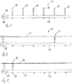
- the presentation of the Fig. 7 shows sections of a profile processing apparatus 10 according to the prior art.
- the profile processing device 10 is intended to process a profile 12.
- the profile 12 is detected on its side facing away from a tool, not shown, by means of a gripper 14 of a feed device and then moved in the directions of a double arrow 16.
- the gripper 14 is also used to transport the profile 12 further through the profile processing device.
- a total of six roller tensioners 18 are provided.
- the roll tensioners 18 are evenly distributed over the length of the profile 12 to reliably guide the profile 12 over its entire length. It will be appreciated that if profile 12 is shorter than illustrated, only some of the roller tensioners 18 will be needed.
- the roller tensioners 18 must also be moved out of the range of movement of the gripper perpendicular to the double arrow 16 in order to allow movement of the gripper 14 and, if necessary, require a large adjustment range.
- the presentation of the Fig. 1 schematically shows a profile machining device 20 according to the invention.
- the profile machining device 20 has a machine frame 22 which stands on a ground surface 24.
- a tool 26 is arranged, which is provided for the processing of a profile 12 and which can be configured substantially in any desired manner.
- the tool 26 is shown only schematically.
- the tool 26 may for example have a sawing device with a circular saw blade, one or more drilling and milling spindles and also other tools.
- the tool 26 may, for example, also have a turntable whose axis of rotation is arranged parallel to a longitudinal direction of the profile 12, through which the profile 12 is pushed and on which a plurality of tools are arranged.
- a relative movement between the tool 26 and profile 12 is in the profile processing device 20 of Fig.
- the gripper 28 is slidably mounted on a guide rail 32 which is fixed to the machine frame 22.
- the guide rail 32 extends to just before the tool 26, so that the gripper 30 can move the profile 12 during profile machining and during transport on the tool.
- the profile 12 rests on a plurality of support rollers 34, which are arranged uniformly spaced from each other on the machine frame and, in the illustration of Fig. 1 , Both left and right of the tool 26 are arranged. On the support rollers 34, the profile 12 can thus be transported during and after a profile machining by means of the tool 12.
- the support rollers 34 are fixedly arranged in the longitudinal direction, but can at least partially perpendicular to the longitudinal direction, in Fig. 1 Thus, to be raised, or lowered, for example, to temporarily raise the profile 12 to facilitate access of the gripper 30.
- the support rollers 34 may also be referred to as guide rollers.
- the guide rail 32 and the gripper 30 form a feed device for the profile 12.
- a roll tensioner 36 is slidably disposed in the directions of the double arrow 30 further.
- the roller tensioner 36 has a tensioning roller 38, which can be delivered to the profile 12 and pulled back from the profile 12.
- the roll tensioner 36 is slidable along the entire guide rail 32 and thus can be driven into the region of the end of the profile 12 which is gripped by the gripper 30 and also, as in Fig. 1 is shown to be driven just before the tool 26.
- Fig. 1 only one roller tensioner 36 is shown. However, it may be provided a plurality of roller tensioners 36, which are then arranged on the guide rail 32 slidably.
- the guide rail 32 is provided in a manner not shown with a stator of a linear motor.
- the roller tensioner 36 is provided with a rotor of the linear motor and can thereby be moved automatically along the guide rail 32.
- the gripper 28 is also provided with a rotor of the linear motor, so that only one linear motor is required for a movement of both the gripper 28 and the roller tensioner 36 along the guide rail 32.
- the presentation of the Fig. 2 shows the profile processing device 20 of Fig. 1 in a first state, in which a tool 26 facing away from the end face of the profile 12 is to be taken.
- the profile 12 is not straight over its entire length, but is bent in the region of the gripper 28 facing the end upwards.
- the front of the gripper 28 lying end of the profile 12 could not be taken or not correctly.
- Fig. 7 a large, evenly distributed over the entire length of the Eintransport Schemes number of roll tensioners provided.
- a single roller-type tensioner 36 is sufficient to securely grasp the profile 12 at its end facing away from the tool.
- the roller tensioner 36 is moved in the region of the end of the profile 12, which faces away from the tool and which lies in front of the gripper 28 for this purpose.
- This end of the profile 12 is thereby pressed against the roller tensioner 36 opposite Auflagerolle 34 and thereby in a predefined position, namely resting on the Auflagerolle 34.
- the gripper 28 is positioned correctly to the end of the profile 12 and can grip this reliably.
- the presentation of the Fig. 4 shows the profile machining device 20 according to the invention in another state.
- a shorter profile 12 is now to be processed, but the end facing away from the tool and facing the gripper 28 is likewise lifted off the support rollers 34, since the profile 12 does not extend in a straight line over its entire length.
- the roll tensioner 36 is again moved along the guide rail 32 into the region of the end of the profile 12 lying in front of the gripper 28, as in Fig. 5 is shown.
- the profile 12 is pressed against the support roller 34 in the region of an end lying in front of the gripper 28 and the gripper 28 can grasp the profile 12 reliably.
- profiles 12 of any desired length can thus be processed, and even with a deviation from the straightness, these profiles 12 can be gripped reliably by means of the gripper 28, without a large number of roller clamps, as in profile machining devices according to the prior art 18 must be distributed uniformly over the entire Eintransport Scheme the profile processing device.
- the presentation of the Fig. 6 shows the profile machining device 20 according to the invention in another state.
- the tool 12 remote from the end of the profile 12 has been gripped by the gripper 28 and the gripper 28 pushes or pulls the profile 12 in the directions of the double arrow 30 during a profile machining relative to the tool 26, see Fig. 1 ,
- the roll tensioner 36 is now arranged during profile machining so that the profile 12 is guided as evenly as possible.
- the roller tensioner 36 is in the state of Fig. 6 this has been moved approximately to the middle of the distance between the tool and the gripper 28.
- a plurality of displaceable roller clamps 36 may be provided to guide the profile 12 safely.
- the profile-machining device 20 it is thus possible to ensure that a not-so-straight profile can be gripped securely by the gripper 28 or a feed device and, moreover, a guide distributed uniformly over the length of the profile can be ensured during profile machining. Nevertheless, the profile-machining device 20 according to the invention can handle only one or a few roller clamps 36.
Description
- Die Erfindung betrifft eine Profilbearbeitungsvorrichtung mit einem Maschinenrahmen, wenigstens einem Werkzeug zur Profilbearbeitung, wenigstens einer Spanneinrichtung für ein zu bearbeitendes Profil und einer Vorschubeinrichtung zum Bewegen eines zu bearbeitenden Profils in einer Transportrichtung durch die Profilbearbeitungseinrichtung, wobei die Transportrichtung einer Längsrichtung des Profils entspricht und wobei die Spanneinrichtung wenigstens einen Rollenspanner zum Führen des Profils während einer Profilbearbeitung bei gleichzeitiger Bewegung des Profils mittels der Vorschubeinrichtung aufweist. Die Erfindung betrifft auch ein Verfahren zum Bearbeiten von Profilen mit einer erfindungsgemäßen Profilbearbeitungsvorrichtung.
- Aus der US-Patentschrift
US 3,566,932 A ist eine Vorrichtung zum Bearbeiten von gestapeltem Plattenmaterial bekannt. Die Vorrichtung weist einen Maschinenrahmen auf, auf dem der Plattenstapel aufliegt, und ein als Kreissäge ausgebildetes Werkzeug, das an einem Portal befestigt ist. Das Portal ist entlang von Führungsschienen, die zu beiden Seiten des Plattenstapels verlaufen, verschiebbar. Zusätzlich ist das Werkzeug in Querrichtung zu den Führungsschienen am Portal verschiebbar. Links und rechts des Kreissägeblatts sind an dem Werkzeugträger Rollen angeordnet, die während des Bearbeitungsvorgangs auf den Plattenstapel gedrückt werden können. Die Rollen werden zusammen mit dem Werkzeugträger und damit zusammen mit dem Kreissägeblatt bewegt. Eine Bewegung des Plattenstapels relativ zum Maschinenrahmen während einer Bearbeitung des Plattenstapels ist nicht vorgesehen. - Aus der deutschen Gebrauchsmusterschrift
DE 202 03 938 U1 ist eine weitere Bearbeitungsvorrichtung für Plattenmaterial vorgesehen. Ein Werkzeug, bspw. eine Oberfräse, ist an einem Werkzeugträger befestigt, der relativ zu dem zu bearbeiteten Plattenmaterial bewegt werden kann. Der Werkzeugträger ist mit Andrückrollen versehen. Die Andrückrollen sind mit einer Vorschubeinrichtung für das Werkzeug verbunden, so dass die Einspannung mittels der Andrückrollen immer im Bereich des Werkzeugs erfolgen kann, auch wenn das Werkzeug im Verlaufe der Bearbeitung seine Position verändert. - Aus der US-Patentschrift
US 3,648,993 A ist eine Vorrichtung zum Bearbeiten von gestapeltem Plattenmaterial bekannt. Speziell ist vorgesehen, einen Stapel aus Blechplatten mit einem Schneidbrenner zu bearbeiten. Der Schneidbrenner ist an einem Portal angeordnet, das in und entgegen der Längsrichtung der Blechplatten verfahren werden kann. Zusätzlich kann der Schneidbrenner quer zur Längsrichtung an dem Portal verschoben werden. Ein weiteres Portal mit mehreren Andrückrollen ist darüber hinaus vorgesehen, wobei das Portal zwei Reihen von Andrückrollen aufweist, zwischen denen eine Öffnung zum Durchführen des Schneidbrenners vorgesehen ist. Die Andrückrollen müssen dadurch im wesentlichen synchron mit dem Schneidbrenner in oder entgegen der Längsrichtung verfahren werden und können sicherstellen, dass die bearbeiteten Blechplatten in Längsrichtung gesehen vor und hinter dem Schneidbrenner niedergehalten werden. - Mit der Erfindung soll eine flexible und kostengünstige Profilbearbeitungsvorrichtung sowie ein vorteilhaftes Verfahren zum Bearbeiten von Profilen bereitgestellt werden.
- Erfindungsgemäß ist hierzu eine Profilbearbeitungsvorrichtung mit den Merkmalen von Anspruch 1 bzw. ein Verfahren zum Bearbeiten von Profilen mit den Merkmalen von Anspruch 7 vorgesehen. Vorteilhafte Weiterbildungen der Erfindung sind in den Unteransprüchen angegeben.
- Gemäß der Erfindung ist eine Profilbearbeitungsvorrichtung mit einem Maschinenrahmen, wenigstens einem Werkzeug zur Profilbearbeitung, wenigstens einer Spanneinrichtung für ein zu bearbeitendes Profil und einer Vorschubeinrichtung zum Bewegen eines zu bearbeitenden Profils in einer Transportrichtung, die einer Längsrichtung des Profils entspricht, durch die Profilbearbeitungsvorrichtung vorgesehen, wobei die Spanneinrichtung wenigstens einen Rollenspanner zum Führen des Profils während einer Profilbearbeitung bei gleichzeitiger Bewegung des Profils mittels der Vorschubeinrichtung aufweist, wobei die Spanneinrichtung eine Führungsschiene aufweist, die parallel zur Transportrichtung an dem Maschinenrahmen angeordnet ist und wobei der wenigstens eine Rollenspanner in und entgegen der Transportrichtung verschiebbar an der Führungsschiene angeordnet ist.
- Überraschenderweise lässt sich eine erheblich flexiblere und dabei kostengünstigere Ausgestaltung einer Profilbearbeitungsvorrichtung erzielen, indem wenigstens ein Rollenspanner der Spanneinrichtung an einer Führungsschiene in und entgegen der Transportrichtung verschiebbar angeordnet ist. Bei Profilbearbeitungsvorrichtungen tritt unter anderem das Problem auf, dass zum Teil sehr lange Profilstücke bearbeitet werden, die, sei es durch falsche Lagerung oder bereits durch den Herstellungsprozess, nicht hundertprozentig geradlinig verlaufen. Da in der Regel die Profile aber an ihrer dem Werkzeug abgewandten Stirnseite mittels eines Greifers ergriffen und dann während der Profilbearbeitung durch die Profilbearbeitungsvorrichtung transportiert werden, machen solche nicht hundertprozentig geradlinigen Profile dahingehend Schwierigkeiten, dass sie mittels des Greifers nicht erfasst oder nicht in die Spannvorrichtung am Werkzeug eingeführt werden können. Abhilfe wird beim Stand der Technik dadurch geschaffen, dass zahlreiche Rollenspanner über den gesamten Eintransportbereich der Profile verteilt sind. Diese Rollenspanner werden dann in Abhängigkeit der Länge des zu bearbeitenden Profils zugestellt, so dass das Profil über seine gesamte Länge mittels der Rollenspanner geführt und vor allem in einer vorbestimmten Position angeordnet ist, so dass es von einem Greifer problemlos erfasst werden kann. Die verarbeiteten Profillängen betragen aber beispielsweise sechs Meter, so dass eine Vielzahl von Rollenspannern, beispielsweise zehn oder mehr Rollenspanner, im Eintransportbereich erforderlich sind. Indem nun wenigstens ein Rollenspanner in und entgegen der Transportrichtung an einer Führungsschiene verschiebbar ist, kann dieser verschiebbare Rollenspanner an diejenige Position gefahren werden, an der er benötigt wird, also üblicherweise an das freie Stirnende des Profils, das dann vom Greifer ergriffen werden muss und anschließend an das dem Werkzeug zugewandte Stirnende, so dass dieses dann problemlos in die Spannvorrichtung am Werkzeug eingeführt werden kann. Die überraschend einfache erfindungsgemäße Lösung ermöglicht es dadurch, mit einem oder nur wenigen verschiebbaren Rollenspannern anstelle von einer Vielzahl von fest angeordneten Rollenspannern auszukommen.
- In Weiterbildung der Erfindung erstreckt sich die Führungsschiene im Wesentlichen über einen gesamten Eintransportbereich für Profile bis zum Werkzeug.
- Auf diese Weise kann sichergestellt werden, dass der verschiebbare Rollenspanner unabhängig von der Länge des zu bearbeitenden Profils immer in den Bereich der Stirnseite des Profils gefahren werden kann, die von dem Greifer einer Vorschubeinrichtung erfasst werden soll.
- In Weiterbildung der Erfindung sind über den gesamten Eintransportbereich Auflagerollen und/oder Führungsrollen für ein zu bearbeitendes Profil angeordnet.
- Beispielsweise weist der Eintransporttisch in Längsrichtung fest angeordnete Auflagerollen und/oder Führungsrollen auf und der Rollenspanner muss dadurch lediglich eine einzige, in Richtung auf das Profil zustellbare Spannrolle aufweisen. Die Auflagerollen und/oder Führungsrollen können senkrecht zur Längsrichtung bewegbar sein, um das zu bearbeitende Profil anzuheben, beispielsweise um einen Zugriff des Greifers zu ermöglichen.
- In Weiterbildung der Erfindung sind mehrere entlang der Führungsschiene verschiebbare Rollenspanner vorgesehen.
- Auf diese Weise kann einer der Rollenspanner in dem Bereich der Stirnseite des zu bearbeitenden Profils verfahren werden und der oder die übrigen Rollenspanner werden so auf die Länge des Profils verteilt, dass während einer Profilbearbeitung eine Führung des Profils über seine gesamte Länge möglich ist. Gegenüber fest angeordneten Rollenspannern wird dadurch eine Bearbeitungspräzision erhöht, da die Abstände der Rollenspanner auf die gerade vorgenommene Bearbeitung und auf das zu verarbeitende Profil abgestimmt werden können.
- In Weiterbildung der Erfindung ist die Führungsschiene mit einem Stator eines Linearmotors und jeder Rollenspanner mit einem Läufer des Linearmotors versehen.
- Auf diese Weise können auch mehrere Rollenspanner auf einem einzigen Stator verschoben werden.
- In Weiterbildung der Erfindung weist die Vorschubeinrichtung einen Greifer zum Ergreifen einer Stirnseite eines zu bearbeitenden Profils auf.
- Mittels eines solchen Greifers kann ein zu bearbeitendes Profil sicher gehalten und präzise und mit hoher Haltekraft während der Profilbearbeitung in und entgegen der Transportrichtung verschoben werden.
- In Weiterbildung der Erfindung ist der Greifer mit einem Läufer des Linearmotors versehen.
- Auf diese Weise können sowohl die Rollenspanner als auch der Greifer der Vorschubeinrichtung auf ein und desselben Stator verschoben werden. Die Kosten für den Stator des Linearmotors fallen dadurch nur einmal an und können für die Verschiebung des Greifers als auch eines Rollenspanners oder mehrerer Rollenspanner genutzt werden.
- Bei einem erfindungsgemäßen Verfahren zum Bearbeiten von Profilen mit einer erfindungsgemäßen Profilbearbeitungsvorrichtung ist das Erfassen der Position eines dem Werkzeug abgewandten Endes des Profils im Eintransportbereich, das Bewegen wenigstens eines Rollenspanners in einen Bereich des Profils, der an das dem Werkzeug abgewandte Ende angrenzt und das Zustellen einer Spannrolle des Rollenspanners in Richtung auf das Profil bis zur Anlage am Profil vorgesehen.
- Auf diese Weise kann das dem Werkzeug abgewandte Ende des Profils in eine vordefinierte Lage gebracht werden, in der es dann von der Vorschubeinrichtung zuverlässig erfasst werden kann. Dadurch können auch Profile, die nicht hundertprozentig geradlinig sind, mit ihrem dem Werkzeug abgewandten Ende in eine vordefinierte Position gebracht und dadurch sicher gegriffen werden.
- In Weiterbildung der Erfindung ist das Ergreifen einer Stirnseite eines zu bearbeitenden Profils mit einem Greifer nach dem Zustellen und Anlegen der Spannrolle des Rollenspanners an das Profil in dem Bereich des Profils, der an das dem Werkzeug abgewandte Ende des Profils angrenzt, vorgesehen.
- Mittels eines Greifers kann das Stirnende eines Profils sicher gehalten werden und während der Profilbearbeitung kann das Profil in und entgegen der Transportrichtung relativ zum Werkzeug bewegt werden.
- Weitere Merkmale und Vorteile der Erfindung ergeben sich aus den Ansprüchen und der folgenden Beschreibung bevorzugter Ausführungsformen der Erfindung im Zusammenhang mit den Zeichnungen. Einzelmerkmale der unterschiedlichen Ausführungsformen können dabei in beliebiger Weise miteinander kombiniert werden, ohne den Rahmen der Erfindung zu überschreiten. In den Zeichnungen zeigen:
- Fig. 1
- eine abschnittsweise schematische Darstellung einer erfindungsgemäßen Profilbearbeitungsvorrichtung,
- Fig. 2
- eine abschnittsweise schematische Darstellung einer erfindungsgemäßen Profilbearbeitungsvorrichtung in einem ersten Zustand,
- Fig. 3
- die Profilbearbeitungsvorrichtung der
Fig. 2 in einem zweiten Zustand, - Fig. 4
- die Profilbearbeitungsvorrichtung der
Fig. 2 in einem dritten Zustand, - Fig. 5
- die Profilbearbeitungsvorrichtung der
Fig. 2 in einem vierten Zustand, - Fig. 6
- die Profilbearbeitungsvorrichtung der
Fig. 2 in einem fünften Zustand und - Fig. 7
- eine schematische Darstellung einer Profilbearbeitungsvorrichtung. gemäß dem Stand der Technik.
- Die Darstellung der
Fig. 7 zeigt abschnittsweise eine Profilbearbeitungsvorrichtung 10 gemäß dem Stand der Technik. Die Profilbearbeitungsvorrichtung 10 ist dafür vorgesehen, ein Profil 12 zu bearbeiten. Hierzu wird das Profil 12 an seiner, einem nicht dargestellten Werkzeug abgewandten Seite, mittels eines Greifers 14 einer Vorschubeinrichtung erfasst und dann in den Richtungen eines Doppelpfeils 16 bewegt. Beispielsweise wird, um einen Schlitz in das Profil 12 zu fräsen, das Profil 12 in der Darstellung derFig. 7 nach rechts oder nach links bewegt. Nach Abschluss eines Abschnitts der Profilbearbeitung wird der Greifer 14 auch dazu genutzt, das Profil 12 weiter durch die Profilbearbeitungsvorrichtung zu transportieren. - Um das Profil 12 während der Profilbearbeitung zu führen, sind insgesamt sechs Rollenspanner 18 vorgesehen. Die Rollenspanner 18 sind gleichmäßig über die Länge des Profils 12 verteilt, um das Profil 12 über seine gesamte Länge zuverlässig zu führen. Es ist ersichtlich, dass dann, wenn das Profil 12 kürzer als dargestellt ist, nur einige der Rollenspanner 18 benötigt werden. Die Rollenspanner 18 müssen auch, um eine Bewegung des Greifers 14 zu ermöglichen, senkrecht zu dem Doppelpfeil 16 aus dem Bewegungsbereich des Greifers herausgefahren werden und benötigen hierfür gegebenenfalls einen großen Verstellbereich. Die Darstellung der
Fig. 1 zeigt schematisch eine erfindungsgemäße Profilbearbeitungsvorrichtung 20. Die Profilbearbeitungsvorrichtung 20 weist einen Maschinenrahmen 22 auf, der auf einer Bodenoberfläche 24 steht. An dem Maschinenrahmen 22 ist ein Werkzeug 26 angeordnet, das für die Bearbeitung eines Profils 12 vorgesehen ist und das im Wesentlichen in beliebiger Weise ausgestaltet sein kann. In der Darstellung derFig. 1 ist das Werkzeug 26 lediglich schematisch dargestellt. Das Werkzeug 26 kann beispielsweise eine Sägeeinrichtung mit einem Kreissägeblatt, einen oder mehrere Bohr- und Frässpindeln sowie auch weitere Werkzeuge aufweisen. Das Werkzeug 26 kann beispielsweise auch einen Drehkranz aufweisen, dessen Drehachse parallel zu einer Längsrichtung des Profils 12 angeordnet ist, durch den das Profil 12 hindurchgeschoben wird und an dem mehrere Werkzeuge angeordnet sind. Eine Relativbewegung zwischen Werkzeug 26 und Profil 12 wird bei der Profilbearbeitungsvorrichtung 20 derFig. 1 zum einen dadurch erreicht, dass während eines Angriffs des Werkzeugs 26 an dem Profil 12 dieses mittels eines Greifers 28 einer Vorschubeinrichtung in den Richtungen eines Doppelpfeils 30 bewegt wird. Zum anderen kann das Werkzeug 26 in zu dem Doppelpfeil 30 senkrechten Richtungen bewegt werden, in der Darstellung derFig. 1 also nach oben und unten und in die Zeichenebene derFig. 1 hinein und aus dieser heraus. - Der Greifer 28 ist an einer Führungsschiene 32 verschiebbar angeordnet, die an dem Maschinenrahmen 22 befestigt ist. Die Führungsschiene 32 erstreckt sich bis kurz vor das Werkzeug 26, so dass der Greifer 30 das Profil 12 während einer Profilbearbeitung und während eines Transports am Werkzeug vorbeibewegen kann. Das Profil 12 liegt auf mehreren Auflagerollen 34 auf, die gleichmäßig voneinander beabstandet an dem Maschinenrahmen angeordnet sind und, in der Darstellung der
Fig. 1 , sowohl links als auch rechts des Werkzeugs 26 angeordnet sind. Auf den Auflagerollen 34 kann das Profil 12 somit während und nach einer Profilbearbeitung mittels des Werkzeugs 12 transportiert werden. Die Auflagerollen 34 sind in Längsrichtung fest angeordnet, können aber zumindest teilweise senkrecht zur Längsrichtung, inFig. 1 also nach oben, angehoben beziehungsweise, abgesenkt werden, beispielsweise um das Profil 12 zeitweise anzuheben, um einen Zugriff des Greifers 30 zu erleichtern. Die Auflagerollen 34 können auch als Führungsrollen bezeichnet werden. - Die Führungsschiene 32 und der Greifer 30 bilden eine Vorschubeinrichtung für das Profil 12.
- An der Führungsschiene 32 ist in den Richtungen des Doppelpfeils 30 verschiebbar weiter ein Rollenspanner 36 angeordnet. Der Rollenspanner 36 weist eine Spannrolle 38 auf, die auf das Profil 12 zugestellt und wieder von dem Profil 12 zurückgezogen werden kann. Der Rollenspanner 36 ist entlang der gesamten Führungsschiene 32 verschiebbar und kann somit in den Bereich des Endes des Profils 12, das vom Greifer 30 ergriffen ist, gefahren werden und auch, wie in
Fig. 1 dargestellt ist, bis unmittelbar vor das Werkzeug 26 gefahren werden. In der schematischen Darstellung derFig. 1 ist lediglich ein Rollenspanner 36 dargestellt. Es können aber mehrere Rollenspanner 36 vorgesehen sein, die dann alle auf der Führungsschiene 32 verschiebbar angeordnet sind. - Die Führungsschiene 32 ist in nicht dargestellter Weise mit einem Stator eines Linearmotors versehen. Der Rollenspanner 36 ist mit einem Läufer des Linearmotors versehen und kann dadurch automatisch entlang der Führungsschiene 32 verschoben werden.
- Der Greifer 28 ist ebenfalls mit einem Läufer des Linearmotors versehen, so dass für eine Bewegung sowohl des Greifers 28 als auch des Rollenspanners 36 entlang der Führungsschiene 32 lediglich ein Linearmotor benötigt wird.
- Die Darstellung der
Fig. 2 zeigt die Profilbearbeitungsvorrichtung 20 derFig. 1 in einem ersten Zustand, in dem eine dem Werkzeug 26 abgewandte Stirnseite des Profils 12 ergriffen werden soll. WieFig. 2 zu entnehmen ist, ist das Profil 12 nicht über seine gesamte Länge geradlinig, sondern ist im Bereich des dem Greifer 28 zugewandten Endes nach oben gebogen. In dem Zustand derFig. 2 könnte das vor dem Greifer 28 liegende Ende des Profils 12 daher nicht oder nicht korrekt ergriffen werden. Um solche gebogenen Profile zuverlässig ergreifen zu können, ist, wie bereits erörtert wurde, beim Stand der Technik, sieheFig. 7 , eine große, gleichmäßig über die gesamte Länge des Eintransportbereichs verteilte Anzahl an Rollenspannern vorgesehen. - Bei der erfindungsgemäßen Profilbearbeitungsvorrichtung 20 genügt hingegen ein einziger Rollenspanner 36, um das Profil 12 an seinem dem Werkzeug abgewandten Ende sicher zu ergreifen.
- Wie in
Fig. 3 dargestellt ist, wird hierzu der Rollenspanner 36 in den Bereich des Endes des Profils 12 verfahren, das dem Werkzeug abgewandt ist und das vor dem Greifer 28 liegt. Dieses Ende des Profils 12 wird dadurch gegen die dem Rollenspanner 36 gegenüberliegende Auflagerolle 34 gedrückt und dadurch in einer vordefinierten Position, nämlich auf der Auflagerolle 34 aufliegend, angeordnet. In dieser Position ist, wie inFig. 3 dargestellt ist, der Greifer 28 korrekt zu dem Ende des Profils 12 positioniert und kann dieses zuverlässig ergreifen. - Die Darstellung der
Fig. 4 zeigt die erfindungsgemäße Profilbearbeitungsvorrichtung 20 in einem weiteren Zustand. Verarbeitet werden soll nun ein kürzeres Profil 12, dessen, dem Werkzeug ab- und dem Greifer 28 zugewandtes Ende aber ebenfalls von den Auflagerollen 34 abgehoben ist, da das Profil 12 nicht über seine gesamte Länge geradlinig verläuft. Um dieses Profil 12 zu greifen, wird nun wieder der Rollenspanner 36 entlang der Führungsschiene 32 in den Bereich des vor dem Greifer 28 liegenden Endes des Profils 12 verfahren, wie inFig. 5 dargestellt ist. Dadurch wird das Profil 12 im Bereich eines vor dem Greifer 28 liegenden Endes gegen die Auflagerolle 34 gedrückt und der Greifer 28 kann das Profil 12 zuverlässig ergreifen. - Mit der erfindungsgemäßen Profilbearbeitungsvorrichtung 20 können somit Profile 12 beliebiger Länge verarbeitet werden und auch bei einer Abweichung von der Geradlinigkeit können diese Profile 12 zuverlässig mittels des Greifers 28 gegriffen werden, ohne dass, wie bei Profilbearbeitungsvorrichtungen gemäß dem Stand der Technik, eine große Anzahl an Rollenspannern 18 gleichmäßig über den gesamten Eintransportbereich der Profilbearbeitungsvorrichtung verteilt sein müssen.
- Die Darstellung der
Fig. 6 zeigt die erfindungsgemäße Profilbearbeitungsvorrichtung 20 in einem weiteren Zustand. Das dem Werkzeug abgewandte Ende des Profils 12 ist vom Greifer 28 ergriffen worden und der Greifer 28 schiebt oder zieht nun das Profil 12 in den Richtungen des Doppelpfeils 30 während einer Profilbearbeitung relativ zum Werkzeug 26, sieheFig. 1 . Der Rollenspanner 36 ist während der Profilbearbeitung nun so angeordnet, dass das Profil 12 möglichst gleichmäßig geführt ist. Der Rollenspanner 36 ist im Zustand derFig. 6 hierzu etwa auf die Mitte des Abstands zwischen dem Werkzeug und dem Greifer 28 verfahren worden. Wie bereits ausgeführt wurde, können mehrere verschiebbare Rollenspanner 36 vorgesehen sein, um das Profil 12 sicher zu führen. - Bei der erfindungsgemäßen Profilbearbeitungsvorrichtung 20 kann somit sichergestellt werden, dass auch ein nicht hundertprozentig geradliniges Profil von dem Greifer 28 bzw. einer Vorschubeinrichtung sicher gegriffen werden kann und darüber hinaus kann eine über die Länge des Profils gleichmäßig verteilte Führung während einer Profilbearbeitung sichergestellt werden. Die erfindungsgemäße Profilbearbeitungsvorrichtung 20 kommt dennoch mit nur einem oder wenigen Rollenspannern 36 aus.
Claims (7)
- Profilbearbeitungsvorrichtung mit einem Maschinenrahmen (22), wenigstens einem Werkzeug (26) zur Profilbearbeitung, wenigstens einer Spanneinrichtung für ein zu bearbeitendes Profil (12) und einer Vorschubeinrichtung zum Bewegen eines zu bearbeitenden Profils (12) in einer Transportrichtung, die einer Längsrichtung des Profils (12) entspricht, durch die Profilbearbeitungseinrichtung (20), wobei die Spanneinrichtung wenigstens einen Rollenspanner (36) zum Führen des Profils (12) während einer Profilbearbeitung bei gleichzeitiger Bewegung des Profils mittels der Vorschubeinrichtung aufweist, dadurch gekennzeichnet, dass die Spanneinrichtung eine Führungsschiene (32) aufweist, die parallel zur Transportrichtung an dem Maschinenrahmen (22) angeordnet ist, wobei der wenigstens eine Rollenspanner (36) in und entgegen der Transportrichtung verschiebbar an der Führungsschiene (32) angeordnet ist, dass sich die Führungsschiene (32) im Wesentlichen über einen gesamten Eintransportbereich für Profile (12) bis zum Werkzeug (26) erstreckt, und dass die Vorschubeinrichtung einen Greifer (28) zum Ergreifen einer Stirnseite eines zu bearbeitenden Profils (12) aufweist, wobei Mittel zum Erfassen einer Position der dem Werkzeug (26) abgewandten Stirnseite des Profils (12) in Eintransportbereich und Mittel zum Bewegen des wenigstens einen Rollenspanners (36) in einen Bereich des Profils (12), der an die dem Werkzeug abgewandte Stirnseite angrenzt, vorgesehen sind.
- Profilbearbeitungsvorrichtung nach Anspruch 1, dadurch gekennzeichnet, dass über den gesamten Eintransportbereich Auflagerollen und/oder Führungsrollen (34) für ein zu bearbeitendes Profil (12) angeordnet sind.
- Profilbearbeitungsvorrichtung nach einem der vorstehenden Ansprüche, dadurch gekennzeichnet, dass mehrere entlang der Führungsschiene (32) verschiebbare Rollenspanner (36) vorgesehen sind.
- Profilbearbeitungsvorrichtung nach Anspruch 3, dadurch gekennzeichnet, dass die Führungsschiene (32) mit einem Stator eines Linearmotors und jeder Rollenspanner (36) mit einem Läufer des Linearmotors versehen ist.
- Profilbearbeitungseinrichtung nach einem der vorstehenden Ansprüche, dadurch gekennzeichnet, dass der Greifer (28) auf der Führungsschiene verschiebbar angeordnet ist.
- Profilbearbeitungsvorrichtung nach einem der vorstehenden Ansprüche, dadurch gekennzeichnet, dass der Greifer (28) mit einem Läufer des Linearmotors versehen ist.
- Verfahren zum Bearbeiten von Profilen mit einer Profilbearbeitungsvorrichtung nach einem der vorstehenden Ansprüche, gekennzeichnet durch Erfassen der Position einer dem Werkzeug (26) abgewandten Stirnseite des Profils (12) im Eintransportbereich, Bewegen wenigstens eines Rollenspanners (36) in einen Bereich des Profils (12), der an die dem Werkzeug (26) abgewandte Stirnseite angrenzt, Zustellen einer Spannrolle (38) des Rollenspanners (36) in Richtung auf das Profil (12) und Ergreifen der Stirnseite des zu bearbeitenden Profils (12) mit einem Greifer (28) der Vorschubeinrichtung nach dem Zustellen der Spannrolle (38) des Rollenspanners (36) an das Profil (12) in dem Bereich des Profils (12), der an die dem Werkzeug (26) abgewandte Stirnseite des Profils (12) angrenzt.
Applications Claiming Priority (1)
| Application Number | Priority Date | Filing Date | Title |
|---|---|---|---|
| DE102014205405.2A DE102014205405B4 (de) | 2014-03-24 | 2014-03-24 | Profilbearbeitungsvorrichtung und Verfahren zum Bearbeiten von Profilen |
Publications (2)
| Publication Number | Publication Date |
|---|---|
| EP2926942A1 EP2926942A1 (de) | 2015-10-07 |
| EP2926942B1 true EP2926942B1 (de) | 2017-01-11 |
Family
ID=52997824
Family Applications (1)
| Application Number | Title | Priority Date | Filing Date |
|---|---|---|---|
| EP15159239.1A Active EP2926942B1 (de) | 2014-03-24 | 2015-03-16 | Profilbearbeitungsvorrichtung und verfahren zum bearbeiten von profilen |
Country Status (2)
| Country | Link |
|---|---|
| EP (1) | EP2926942B1 (de) |
| DE (1) | DE102014205405B4 (de) |
Cited By (1)
| Publication number | Priority date | Publication date | Assignee | Title |
|---|---|---|---|---|
| CN108788298A (zh) * | 2018-07-24 | 2018-11-13 | 浙江威力士机械有限公司 | 金属料棒切断圆锯机 |
Families Citing this family (3)
| Publication number | Priority date | Publication date | Assignee | Title |
|---|---|---|---|---|
| ITUA20163993A1 (it) * | 2016-05-31 | 2017-12-01 | F O M Ind S R L | Macchina per la lavorazione di profilati |
| CN107971576A (zh) * | 2017-12-15 | 2018-05-01 | 湖南新融创科技有限公司 | 一种五金零部件生产加工用切割装置 |
| IT201900022962A1 (it) * | 2019-12-04 | 2021-06-04 | Lorenzo Lattanzi | Dispositivo di avanzamento |
Family Cites Families (9)
| Publication number | Priority date | Publication date | Assignee | Title |
|---|---|---|---|---|
| US3566932A (en) | 1968-04-04 | 1971-03-02 | Guenther Papenmeier | Process for rational production of size plates with a plate saw, in particular using an electronic control and device for practicing |
| US3648993A (en) * | 1970-06-30 | 1972-03-14 | Mitsubishi Heavy Ind Ltd | Work piece pressing device in automatic stack gas cutting |
| IT1169821B (it) * | 1983-09-13 | 1987-06-03 | Teax Srl | Macchina per la foratura di materiali lastriformi fragili,in paticolare di lastre in vetro e simili |
| DE4401271C2 (de) | 1994-01-18 | 1997-06-12 | Schmidler Maschinenbau Gmbh | Abbundanlage mit Transporteinrichtungen |
| US6116126A (en) | 1996-07-10 | 2000-09-12 | Van Den Bulcke; Marc | Method and machine for making profile pieces |
| DE19905876A1 (de) | 1999-02-12 | 2000-08-17 | Hans Hundegger | Holzbearbeitungsanlage in Portalbauweise |
| DE20203938U1 (de) * | 2002-03-12 | 2002-06-06 | Wassmer Spezialmaschinen Gmbh | Bearbeitungsmaschine zum wenigstens teilweisen konturenabhängigen Ausschneiden oder Fräsen |
| DE102005002595B4 (de) | 2005-01-20 | 2007-02-08 | Holzma Plattenaufteiltechnik Gmbh | Greifeinrichtung, insbesondere Spannzange, zur Verwendung bei einer Vorschubvorrichtung für plattenförmige Werkstücke |
| DE102008026330A1 (de) | 2008-05-31 | 2009-12-03 | Holzma Plattenaufteiltechnik Gmbh | Plattenaufteilanlage |
-
2014
- 2014-03-24 DE DE102014205405.2A patent/DE102014205405B4/de active Active
-
2015
- 2015-03-16 EP EP15159239.1A patent/EP2926942B1/de active Active
Non-Patent Citations (1)
| Title |
|---|
| None * |
Cited By (2)
| Publication number | Priority date | Publication date | Assignee | Title |
|---|---|---|---|---|
| CN108788298A (zh) * | 2018-07-24 | 2018-11-13 | 浙江威力士机械有限公司 | 金属料棒切断圆锯机 |
| CN108788298B (zh) * | 2018-07-24 | 2019-07-23 | 浙江威力士机械有限公司 | 金属料棒切断圆锯机 |
Also Published As
| Publication number | Publication date |
|---|---|
| DE102014205405B4 (de) | 2020-06-25 |
| EP2926942A1 (de) | 2015-10-07 |
| DE102014205405A1 (de) | 2015-09-24 |
Similar Documents
| Publication | Publication Date | Title |
|---|---|---|
| WO2016045968A1 (de) | Bearbeitungsvorrichtung | |
| EP0988924B2 (de) | Holzbearbeitungsanlage | |
| EP2926942B1 (de) | Profilbearbeitungsvorrichtung und verfahren zum bearbeiten von profilen | |
| WO2017055111A1 (de) | Bearbeitungsvorrichtung | |
| DE102007035743B4 (de) | Bearbeitungsstation zum Bearbeiten von plattenförmigen Werkstücken | |
| DE102018008199A1 (de) | Verfahren zum Bearbeiten von länglichen Werkstücken aus Holz, Kunststoff und dergleichen sowie Maschine zur Durchführung des Verfahrens | |
| EP2926943A1 (de) | Profilbearbeitungsvorrichtung und Verfahren zum Bearbeiten von Profilen | |
| WO2016071351A1 (de) | Spannvorrichtung | |
| EP2481540B1 (de) | Einrichtung zum Zersägen von zumindest zwei platten- oder plattenstapelförmigen Werkstücken | |
| EP2774708B1 (de) | Sägemaschine zum Zersägen zumindest eines plattenförmigen Werkstücks | |
| EP2371480B1 (de) | Profilbearbeitungszentrum | |
| EP3023193A1 (de) | Werkstückzuführvorrichtung | |
| EP2404691B1 (de) | Drehkranzeinheit für ein Profilbearbeitungszentrum | |
| DE3737228A1 (de) | Einrichtung zum buntaufteilen von plattenfoermigen werkstuecken | |
| EP2810754A1 (de) | Verfahren zum Bearbeiten eines Baumstammes | |
| EP1764177B1 (de) | Ablängvorrichtung für Glasleisten oder entsprechende Stabprofile und Verfahren zum Ablängen von Glasleisten oder entsprechenden Stabprofilen | |
| EP2236232B1 (de) | Sägemaschine | |
| EP3069837B1 (de) | Bearbeitungsvorrichtung | |
| EP2185331A1 (de) | Vorrichtung zur bearbeitung von werkstücken aus holz, kunststoff und dergleichen sowie verfahren zum bearbeiten von solchen werkstücken | |
| EP2030725B1 (de) | Vorrichtung und Verfahren zum Ausrichten von Werkstücken | |
| DE10303136B3 (de) | Band- und Platinenabstützung für ein Schneidwerkzeug mit zwei Schneidbalken | |
| DE102011102793B3 (de) | Verfahren zur Bearbeitung der Stirnseiten von Werkstücken aus Holz, Kunststoff und dergleichen | |
| WO2016180651A1 (de) | Werkstückzuführvorrichtung bzw. werkstückabführvorrichtung | |
| DE102012111879A1 (de) | Verfahren und Vorrichtung zum Bearbeiten von Platten | |
| DE102019003699A1 (de) | Werkstück-Bereitstellungsgruppe für eine Bearbeitungsstation |
Legal Events
| Date | Code | Title | Description |
|---|---|---|---|
| PUAI | Public reference made under article 153(3) epc to a published international application that has entered the european phase |
Free format text: ORIGINAL CODE: 0009012 |
|
| AK | Designated contracting states |
Kind code of ref document: A1 Designated state(s): AL AT BE BG CH CY CZ DE DK EE ES FI FR GB GR HR HU IE IS IT LI LT LU LV MC MK MT NL NO PL PT RO RS SE SI SK SM TR |
|
| AX | Request for extension of the european patent |
Extension state: BA ME |
|
| 17P | Request for examination filed |
Effective date: 20160122 |
|
| RBV | Designated contracting states (corrected) |
Designated state(s): AL AT BE BG CH CY CZ DE DK EE ES FI FR GB GR HR HU IE IS IT LI LT LU LV MC MK MT NL NO PL PT RO RS SE SI SK SM TR |
|
| RIC1 | Information provided on ipc code assigned before grant |
Ipc: B23Q 7/05 20060101ALI20160707BHEP Ipc: B23Q 7/04 20060101ALI20160707BHEP Ipc: B23Q 3/06 20060101AFI20160707BHEP Ipc: B23D 47/04 20060101ALI20160707BHEP |
|
| GRAP | Despatch of communication of intention to grant a patent |
Free format text: ORIGINAL CODE: EPIDOSNIGR1 |
|
| INTG | Intention to grant announced |
Effective date: 20160817 |
|
| GRAS | Grant fee paid |
Free format text: ORIGINAL CODE: EPIDOSNIGR3 |
|
| GRAJ | Information related to disapproval of communication of intention to grant by the applicant or resumption of examination proceedings by the epo deleted |
Free format text: ORIGINAL CODE: EPIDOSDIGR1 |
|
| GRAL | Information related to payment of fee for publishing/printing deleted |
Free format text: ORIGINAL CODE: EPIDOSDIGR3 |
|
| GRAP | Despatch of communication of intention to grant a patent |
Free format text: ORIGINAL CODE: EPIDOSNIGR1 |
|
| GRAA | (expected) grant |
Free format text: ORIGINAL CODE: 0009210 |
|
| INTC | Intention to grant announced (deleted) | ||
| INTG | Intention to grant announced |
Effective date: 20161128 |
|
| AK | Designated contracting states |
Kind code of ref document: B1 Designated state(s): AL AT BE BG CH CY CZ DE DK EE ES FI FR GB GR HR HU IE IS IT LI LT LU LV MC MK MT NL NO PL PT RO RS SE SI SK SM TR |
|
| REG | Reference to a national code |
Ref country code: GB Ref legal event code: FG4D Free format text: NOT ENGLISH |
|
| REG | Reference to a national code |
Ref country code: CH Ref legal event code: EP |
|
| REG | Reference to a national code |
Ref country code: AT Ref legal event code: REF Ref document number: 860816 Country of ref document: AT Kind code of ref document: T Effective date: 20170115 |
|
| REG | Reference to a national code |
Ref country code: IE Ref legal event code: FG4D Free format text: LANGUAGE OF EP DOCUMENT: GERMAN |
|
| REG | Reference to a national code |
Ref country code: DE Ref legal event code: R096 Ref document number: 502015000487 Country of ref document: DE |
|
| REG | Reference to a national code |
Ref country code: FR Ref legal event code: PLFP Year of fee payment: 3 |
|
| REG | Reference to a national code |
Ref country code: LT Ref legal event code: MG4D |
|
| REG | Reference to a national code |
Ref country code: NL Ref legal event code: MP Effective date: 20170111 |
|
| PG25 | Lapsed in a contracting state [announced via postgrant information from national office to epo] |
Ref country code: NL Free format text: LAPSE BECAUSE OF FAILURE TO SUBMIT A TRANSLATION OF THE DESCRIPTION OR TO PAY THE FEE WITHIN THE PRESCRIBED TIME-LIMIT Effective date: 20170111 |
|
| PG25 | Lapsed in a contracting state [announced via postgrant information from national office to epo] |
Ref country code: HR Free format text: LAPSE BECAUSE OF FAILURE TO SUBMIT A TRANSLATION OF THE DESCRIPTION OR TO PAY THE FEE WITHIN THE PRESCRIBED TIME-LIMIT Effective date: 20170111 Ref country code: GR Free format text: LAPSE BECAUSE OF FAILURE TO SUBMIT A TRANSLATION OF THE DESCRIPTION OR TO PAY THE FEE WITHIN THE PRESCRIBED TIME-LIMIT Effective date: 20170412 Ref country code: IS Free format text: LAPSE BECAUSE OF FAILURE TO SUBMIT A TRANSLATION OF THE DESCRIPTION OR TO PAY THE FEE WITHIN THE PRESCRIBED TIME-LIMIT Effective date: 20170511 Ref country code: NO Free format text: LAPSE BECAUSE OF FAILURE TO SUBMIT A TRANSLATION OF THE DESCRIPTION OR TO PAY THE FEE WITHIN THE PRESCRIBED TIME-LIMIT Effective date: 20170411 Ref country code: LT Free format text: LAPSE BECAUSE OF FAILURE TO SUBMIT A TRANSLATION OF THE DESCRIPTION OR TO PAY THE FEE WITHIN THE PRESCRIBED TIME-LIMIT Effective date: 20170111 Ref country code: FI Free format text: LAPSE BECAUSE OF FAILURE TO SUBMIT A TRANSLATION OF THE DESCRIPTION OR TO PAY THE FEE WITHIN THE PRESCRIBED TIME-LIMIT Effective date: 20170111 |
|
| PG25 | Lapsed in a contracting state [announced via postgrant information from national office to epo] |
Ref country code: BG Free format text: LAPSE BECAUSE OF FAILURE TO SUBMIT A TRANSLATION OF THE DESCRIPTION OR TO PAY THE FEE WITHIN THE PRESCRIBED TIME-LIMIT Effective date: 20170411 Ref country code: PL Free format text: LAPSE BECAUSE OF FAILURE TO SUBMIT A TRANSLATION OF THE DESCRIPTION OR TO PAY THE FEE WITHIN THE PRESCRIBED TIME-LIMIT Effective date: 20170111 Ref country code: PT Free format text: LAPSE BECAUSE OF FAILURE TO SUBMIT A TRANSLATION OF THE DESCRIPTION OR TO PAY THE FEE WITHIN THE PRESCRIBED TIME-LIMIT Effective date: 20170511 Ref country code: LV Free format text: LAPSE BECAUSE OF FAILURE TO SUBMIT A TRANSLATION OF THE DESCRIPTION OR TO PAY THE FEE WITHIN THE PRESCRIBED TIME-LIMIT Effective date: 20170111 Ref country code: SE Free format text: LAPSE BECAUSE OF FAILURE TO SUBMIT A TRANSLATION OF THE DESCRIPTION OR TO PAY THE FEE WITHIN THE PRESCRIBED TIME-LIMIT Effective date: 20170111 Ref country code: ES Free format text: LAPSE BECAUSE OF FAILURE TO SUBMIT A TRANSLATION OF THE DESCRIPTION OR TO PAY THE FEE WITHIN THE PRESCRIBED TIME-LIMIT Effective date: 20170111 Ref country code: RS Free format text: LAPSE BECAUSE OF FAILURE TO SUBMIT A TRANSLATION OF THE DESCRIPTION OR TO PAY THE FEE WITHIN THE PRESCRIBED TIME-LIMIT Effective date: 20170111 |
|
| REG | Reference to a national code |
Ref country code: DE Ref legal event code: R097 Ref document number: 502015000487 Country of ref document: DE |
|
| PG25 | Lapsed in a contracting state [announced via postgrant information from national office to epo] |
Ref country code: RO Free format text: LAPSE BECAUSE OF FAILURE TO SUBMIT A TRANSLATION OF THE DESCRIPTION OR TO PAY THE FEE WITHIN THE PRESCRIBED TIME-LIMIT Effective date: 20170111 Ref country code: SK Free format text: LAPSE BECAUSE OF FAILURE TO SUBMIT A TRANSLATION OF THE DESCRIPTION OR TO PAY THE FEE WITHIN THE PRESCRIBED TIME-LIMIT Effective date: 20170111 Ref country code: EE Free format text: LAPSE BECAUSE OF FAILURE TO SUBMIT A TRANSLATION OF THE DESCRIPTION OR TO PAY THE FEE WITHIN THE PRESCRIBED TIME-LIMIT Effective date: 20170111 Ref country code: CZ Free format text: LAPSE BECAUSE OF FAILURE TO SUBMIT A TRANSLATION OF THE DESCRIPTION OR TO PAY THE FEE WITHIN THE PRESCRIBED TIME-LIMIT Effective date: 20170111 |
|
| PLBE | No opposition filed within time limit |
Free format text: ORIGINAL CODE: 0009261 |
|
| STAA | Information on the status of an ep patent application or granted ep patent |
Free format text: STATUS: NO OPPOSITION FILED WITHIN TIME LIMIT |
|
| PG25 | Lapsed in a contracting state [announced via postgrant information from national office to epo] |
Ref country code: MC Free format text: LAPSE BECAUSE OF FAILURE TO SUBMIT A TRANSLATION OF THE DESCRIPTION OR TO PAY THE FEE WITHIN THE PRESCRIBED TIME-LIMIT Effective date: 20170111 Ref country code: DK Free format text: LAPSE BECAUSE OF FAILURE TO SUBMIT A TRANSLATION OF THE DESCRIPTION OR TO PAY THE FEE WITHIN THE PRESCRIBED TIME-LIMIT Effective date: 20170111 Ref country code: SM Free format text: LAPSE BECAUSE OF FAILURE TO SUBMIT A TRANSLATION OF THE DESCRIPTION OR TO PAY THE FEE WITHIN THE PRESCRIBED TIME-LIMIT Effective date: 20170111 |
|
| 26N | No opposition filed |
Effective date: 20171012 |
|
| REG | Reference to a national code |
Ref country code: IE Ref legal event code: MM4A |
|
| PG25 | Lapsed in a contracting state [announced via postgrant information from national office to epo] |
Ref country code: LU Free format text: LAPSE BECAUSE OF NON-PAYMENT OF DUE FEES Effective date: 20170316 |
|
| PG25 | Lapsed in a contracting state [announced via postgrant information from national office to epo] |
Ref country code: IE Free format text: LAPSE BECAUSE OF NON-PAYMENT OF DUE FEES Effective date: 20170316 Ref country code: SI Free format text: LAPSE BECAUSE OF FAILURE TO SUBMIT A TRANSLATION OF THE DESCRIPTION OR TO PAY THE FEE WITHIN THE PRESCRIBED TIME-LIMIT Effective date: 20170111 |
|
| REG | Reference to a national code |
Ref country code: BE Ref legal event code: MM Effective date: 20170331 |
|
| REG | Reference to a national code |
Ref country code: FR Ref legal event code: PLFP Year of fee payment: 4 |
|
| PG25 | Lapsed in a contracting state [announced via postgrant information from national office to epo] |
Ref country code: BE Free format text: LAPSE BECAUSE OF NON-PAYMENT OF DUE FEES Effective date: 20170331 |
|
| PG25 | Lapsed in a contracting state [announced via postgrant information from national office to epo] |
Ref country code: MT Free format text: LAPSE BECAUSE OF FAILURE TO SUBMIT A TRANSLATION OF THE DESCRIPTION OR TO PAY THE FEE WITHIN THE PRESCRIBED TIME-LIMIT Effective date: 20170111 |
|
| REG | Reference to a national code |
Ref country code: CH Ref legal event code: PL |
|
| PG25 | Lapsed in a contracting state [announced via postgrant information from national office to epo] |
Ref country code: LI Free format text: LAPSE BECAUSE OF NON-PAYMENT OF DUE FEES Effective date: 20180331 Ref country code: CH Free format text: LAPSE BECAUSE OF NON-PAYMENT OF DUE FEES Effective date: 20180331 |
|
| PG25 | Lapsed in a contracting state [announced via postgrant information from national office to epo] |
Ref country code: HU Free format text: LAPSE BECAUSE OF FAILURE TO SUBMIT A TRANSLATION OF THE DESCRIPTION OR TO PAY THE FEE WITHIN THE PRESCRIBED TIME-LIMIT; INVALID AB INITIO Effective date: 20150316 |
|
| PG25 | Lapsed in a contracting state [announced via postgrant information from national office to epo] |
Ref country code: CY Free format text: LAPSE BECAUSE OF FAILURE TO SUBMIT A TRANSLATION OF THE DESCRIPTION OR TO PAY THE FEE WITHIN THE PRESCRIBED TIME-LIMIT Effective date: 20170111 |
|
| PG25 | Lapsed in a contracting state [announced via postgrant information from national office to epo] |
Ref country code: MK Free format text: LAPSE BECAUSE OF FAILURE TO SUBMIT A TRANSLATION OF THE DESCRIPTION OR TO PAY THE FEE WITHIN THE PRESCRIBED TIME-LIMIT Effective date: 20170111 |
|
| PG25 | Lapsed in a contracting state [announced via postgrant information from national office to epo] |
Ref country code: AL Free format text: LAPSE BECAUSE OF FAILURE TO SUBMIT A TRANSLATION OF THE DESCRIPTION OR TO PAY THE FEE WITHIN THE PRESCRIBED TIME-LIMIT Effective date: 20170111 |
|
| REG | Reference to a national code |
Ref country code: AT Ref legal event code: MM01 Ref document number: 860816 Country of ref document: AT Kind code of ref document: T Effective date: 20200316 |
|
| PG25 | Lapsed in a contracting state [announced via postgrant information from national office to epo] |
Ref country code: AT Free format text: LAPSE BECAUSE OF NON-PAYMENT OF DUE FEES Effective date: 20200316 |
|
| PGFP | Annual fee paid to national office [announced via postgrant information from national office to epo] |
Ref country code: FR Payment date: 20230320 Year of fee payment: 9 |
|
| PGFP | Annual fee paid to national office [announced via postgrant information from national office to epo] |
Ref country code: TR Payment date: 20230315 Year of fee payment: 9 Ref country code: GB Payment date: 20230323 Year of fee payment: 9 Ref country code: DE Payment date: 20230323 Year of fee payment: 9 |
|
| P01 | Opt-out of the competence of the unified patent court (upc) registered |
Effective date: 20230525 |
|
| PGFP | Annual fee paid to national office [announced via postgrant information from national office to epo] |
Ref country code: IT Payment date: 20230331 Year of fee payment: 9 |