EP2370198B1 - Bördelrührer - Google Patents
Bördelrührer Download PDFInfo
- Publication number
- EP2370198B1 EP2370198B1 EP09799550.0A EP09799550A EP2370198B1 EP 2370198 B1 EP2370198 B1 EP 2370198B1 EP 09799550 A EP09799550 A EP 09799550A EP 2370198 B1 EP2370198 B1 EP 2370198B1
- Authority
- EP
- European Patent Office
- Prior art keywords
- stirring
- stirrer
- flange
- flat element
- shaft
- Prior art date
- Legal status (The legal status is an assumption and is not a legal conclusion. Google has not performed a legal analysis and makes no representation as to the accuracy of the status listed.)
- Active
Links
Images


Classifications
-
- B—PERFORMING OPERATIONS; TRANSPORTING
- B01—PHYSICAL OR CHEMICAL PROCESSES OR APPARATUS IN GENERAL
- B01F—MIXING, e.g. DISSOLVING, EMULSIFYING OR DISPERSING
- B01F27/00—Mixers with rotary stirring devices in fixed receptacles; Kneaders
- B01F27/05—Stirrers
- B01F27/051—Stirrers characterised by their elements, materials or mechanical properties
- B01F27/054—Deformable stirrers, e.g. deformed by a centrifugal force applied during operation
- B01F27/0541—Deformable stirrers, e.g. deformed by a centrifugal force applied during operation with mechanical means to alter the position of the stirring elements
-
- B—PERFORMING OPERATIONS; TRANSPORTING
- B01—PHYSICAL OR CHEMICAL PROCESSES OR APPARATUS IN GENERAL
- B01F—MIXING, e.g. DISSOLVING, EMULSIFYING OR DISPERSING
- B01F27/00—Mixers with rotary stirring devices in fixed receptacles; Kneaders
- B01F27/05—Stirrers
- B01F27/07—Stirrers characterised by their mounting on the shaft
- B01F27/071—Fixing of the stirrer to the shaft
-
- B—PERFORMING OPERATIONS; TRANSPORTING
- B01—PHYSICAL OR CHEMICAL PROCESSES OR APPARATUS IN GENERAL
- B01F—MIXING, e.g. DISSOLVING, EMULSIFYING OR DISPERSING
- B01F27/00—Mixers with rotary stirring devices in fixed receptacles; Kneaders
- B01F27/05—Stirrers
- B01F27/07—Stirrers characterised by their mounting on the shaft
- B01F27/072—Stirrers characterised by their mounting on the shaft characterised by the disposition of the stirrers with respect to the rotating axis
- B01F27/0721—Stirrers characterised by their mounting on the shaft characterised by the disposition of the stirrers with respect to the rotating axis parallel with respect to the rotating axis
-
- B—PERFORMING OPERATIONS; TRANSPORTING
- B01—PHYSICAL OR CHEMICAL PROCESSES OR APPARATUS IN GENERAL
- B01F—MIXING, e.g. DISSOLVING, EMULSIFYING OR DISPERSING
- B01F27/00—Mixers with rotary stirring devices in fixed receptacles; Kneaders
- B01F27/05—Stirrers
- B01F27/07—Stirrers characterised by their mounting on the shaft
- B01F27/072—Stirrers characterised by their mounting on the shaft characterised by the disposition of the stirrers with respect to the rotating axis
- B01F27/0726—Stirrers characterised by their mounting on the shaft characterised by the disposition of the stirrers with respect to the rotating axis having stirring elements connected to the stirrer shaft each by a single radial rod, other than open frameworks
-
- B—PERFORMING OPERATIONS; TRANSPORTING
- B01—PHYSICAL OR CHEMICAL PROCESSES OR APPARATUS IN GENERAL
- B01F—MIXING, e.g. DISSOLVING, EMULSIFYING OR DISPERSING
- B01F27/00—Mixers with rotary stirring devices in fixed receptacles; Kneaders
- B01F27/05—Stirrers
- B01F27/11—Stirrers characterised by the configuration of the stirrers
- B01F27/112—Stirrers characterised by the configuration of the stirrers with arms, paddles, vanes or blades
- B01F27/1125—Stirrers characterised by the configuration of the stirrers with arms, paddles, vanes or blades with vanes or blades extending parallel or oblique to the stirrer axis
- B01F27/11251—Stirrers characterised by the configuration of the stirrers with arms, paddles, vanes or blades with vanes or blades extending parallel or oblique to the stirrer axis having holes in the surface
-
- B—PERFORMING OPERATIONS; TRANSPORTING
- B01—PHYSICAL OR CHEMICAL PROCESSES OR APPARATUS IN GENERAL
- B01F—MIXING, e.g. DISSOLVING, EMULSIFYING OR DISPERSING
- B01F27/00—Mixers with rotary stirring devices in fixed receptacles; Kneaders
- B01F27/05—Stirrers
- B01F27/11—Stirrers characterised by the configuration of the stirrers
- B01F27/117—Stirrers provided with conical-shaped elements, e.g. funnel-shaped
Definitions
- the invention relates to an industrial stirrer according to the preamble of patent claim 1.
- Industrial stirrers are used for stirring, mixing or blending substances or substances such as liquids, powdery substances or dough-like masses. In this case, different requirements are placed on the stirring method and the stirring result, wherein an essential criterion is the selection of the geometric shape of a stirring body. Under industrial stirrers is in the present case any type of production technology used stirrers to understand, be it for example stirrers from the food industry, paint industry or from the construction or environmental technology.
- Another selection criterion for the embodiment of a stirrer is always the shape of the stirred tank.
- stirrers which have a plurality of flat stirring bodies with a plurality of smaller passage openings.
- SU 1542601 discloses an industrial stirrer according to the preamble of claim 1.
- the invention has the object, an industrial stirrer in such a way that it can be used at low cost production for a variety of mixing tasks.
- the invention is characterized by the features of claim 1.
- the invention is based on an industrial stirrer with a drive shaft and at least one spoke, whose at least one stirrer body is designed in the stirring direction with a plane-like cross-sectional area.
- the stirring body is moved through a medium to be stirred.
- the stirring direction corresponds to this direction of movement, wherein in the case of a rotating stirrer under the stirring direction substantially at a time tangentially applied to a circular path direction to understand. Along the circular path, the stirring direction thus changes correspondingly to the circular movement of the rotating stirrer.
- the stirring body can be adapted in its shape, in its dimensions and in its position with respect to a stirring shaft generating the stirring without significant restrictions of the respective stirring task.
- the stirrer according to the invention has the feature that the plane-like cross-sectional area of the at least one agitating body is interrupted by a recess, ie it has a hole in the surface area.
- stirred medium such as a highly viscous or jelly-like mass after stirring a mixing / mixing with a required homogeneity, especially in the beginning Having corner regions of square stirred containers.
- the recess is arranged centrally in the plane of the stirring body. Via the centrally arranged recess, an increased symmetry of a flow profile formed during the stirring process is made possible, whereby an improved homogenization can be achieved.
- a Centrally arranged recess further reduces the production costs of such a stirring body, as available standard parts of other industries often this symmetry is present, which are to be used for example as components for producing such a stirring body.
- the at least one stirring body of the stirrer according to the invention is formed from a flat element and a flange.
- the flat element forms an enlarged stirring cross-sectional area in the medium to be stirred in the stirring direction, the flange following the flat element producing a funnel effect and thus influencing the stirring flow profile.
- the flare connects to the central recess.
- the forming Rhackströmungsprofil is further improved in this way, so that, for example, toroidal rotational flow (similar to a Rauchkringels of cigarette smoke) can form around the stirring body.
- the flange is formed in the direction of stirring in relation to the material thickness of the flat body the same length or longer. If the flange is formed the same length in relation to the thickness of the flat body, an optimized flow behavior of the medium is achieved, which achieves a good mixing of the medium to be stirred. If, for example, the crimp in the stirring direction is made longer in relation to the thickness of the flat body, it is possible to utilize the advantages of a tubular stirrer and its stirring behavior in, for example, a viscous medium.
- the surface of the flat element to the surface of the recess in a ratio range of at least 0.5: 1 to (1: x)> 1 is formed.
- Ratio sizes of 0.8 to 8 have been found to be useful combination of annular surface to inner diameter surface which can be realized with standard parts.
- the stirring body forms a sufficient, planar-like cross-sectional area to produce the aforementioned advantages such as a homogeneous medium at low speed of the stirrer.
- the task is given expanded to the effect that with increasing stirring speed a forming axial vortex must not pass through to the stirring body, otherwise air would be introduced into the material to be stirred. This may also be desirable in individual cases.
- the flat element is designed as a round, oval or square body.
- the design of the flat element with different surface shapes has the advantage that the plane-like cross-sectional area of the flat element can be adapted in each case to the stirring task or to the medium or container shape to be stirred.
- the recess and the adjoining flare is round, oval or square. This has the advantage that depending on the stirring task, the cross-sectional area of the recess and the adjoining lateral surface of the flange can be formed differently.
- an alternative attachment of the stirring body to the stirring shaft by, for example, an articulated connection has the advantage that the stirrer can be introduced into a container opening in the pivoted-in state, wherein the diameter of the opening can be smaller than the effective stirring diameter. Due to the centrifugal force, the pendulum arranged on the articulated joint stirring body during the stirring process to a larger effective radius.
- the at least one stirring body is a welding bead, as he, for example, from the Catalog "Welding fittings made of stainless steel VA4" (2008-09-24), fittings Arnold GmbH , XP 002574996 is known.
- This has the advantage that standard parts for the stirring bodies are to be used, for example, for the production of a stirrer according to the invention, which advantageously lowers the production costs of such a stirrer.
- the effective stirring diameter of the stirrer can be adapted to the geometry of the respective stirring container by appropriate length adaptation of the spoke.
- the essence of this aspect is that at least one, preferably three stirring bodies according to the invention are present.
- Stirring vessel and its dimensions are adjusted. With regard to the number of stirring bodies, it is advisable to adjust symmetry considerations around the center of rotation in order to minimize occurring bearing loads on the drive shaft. In principle, however, slow-moving stirrers with a single stirring body are also conceivable.
- the stirring body is rotatably formed on the shaft and / or pivotally mounted on the spoke.
- FIG. 1 a stirrer 1 according to the invention, which arranged on spokes 2 stirring body 3, in the present case arranged radially symmetrically about a hub 4 at a distance of 120 °.
- the stirrers are set slightly inclined relative to the vertical, which is achieved via a rotation along the axis of the spokes 2.
- the hub 4 has in its center further on a shaft receiving 5a, which allows a threaded bore attachment of the stirrer 1 to a motor-driven shaft (not shown here).
- the stirrer 1 is set in rotation via the shaft, in such a way that the stirring bodies 3 are moved along the stirring direction 5.
- the stirring body 3 has, on the one hand, a flat element 6 with a central recess 7, which forms the direction of rotation-related front side. On the stirring direction-related rear side, the stirring body 3 has a flange 8, which adjoins the recess 7 in the present case.
- the stirrer body 3 is thus moved in the stirring direction 5 with the flat element 6 first through the medium to be stirred, wherein the medium to be stirred on the surface of the flat element 6 on the one hand by the recess 7 and the adjoining flare 8, on the other hand also flows around the stirring body 3.
- the stirring bodies 3 are welded to a round material by means of a weld seam 9, which in turn is inserted into a stirring body attachment 10 on the spoke 2.
- the Stirrer attachment 10 comprises a grub screw with which in the present case the round material welded to the stirrer body 3 is tensioned.
- the attached to the spoke 2 Rhakismefest Trent 10 serves as a kind of connection adapter 11, which allows a compound of the stirring body 3 via the spoke 2 with the hub 4 and thus with the driving shaft via the shaft receiving 5.
- connection adapter 11 such as threads, are conceivable.
- connection adapter 11 makes it possible for the stirring bodies 3 to be inclined slightly in their vertical orientation with respect to the drive shaft and thus to provide improved stirring behavior, in particular with respect to a downward pulling force, similar to a screw.
- the spoke 2 is itself in the present case also secured by welds to the hub 4, whereby the stirrer 1 forms a unit of three Rlick emotionsn 3 with corresponding fastening devices and Ardsadaptern.
- the stirring bodies can also be welded to the spokes in the region of the flare or on the surface next to the flare by means of the flanged form, in order to withstand the considerable shearing forces during the stirring.
- Fig. 1 The present in Fig. 1
- the exemplary embodiment shown represents only a prototype. It would be more expedient to design a stirrer in process engineering which, in particular in the area of the food industry, but also in a multiplicity of other applications, has an apparently one-piece construction. This would have to be chosen so that the multiplicity of openings and undercuts shown here would mean an almost impossible complexity with respect to the cleaning of the stirrer 1.
- a corresponding angle of incidence of the Rcken stressesenkrechten against a drive shaft has the advantage that a certain tensile torque is exerted by the screw-like force down on the entire agitator 1, which in turn the rotational movement of the stirrer 1 is stabilized on the shaft, in particular against a rocking of vibration resonances ,
- Fig. 2 shows a stirring body 3 in the form of a weld bead, which in turn corresponds to a standard part.
- the rear view of the weld bead is shown, wherein the welding bead is formed from a flat element 6 and a subsequent bead 8.
- the flange 8 has a flange wall thickness 21 which is chosen to be approximately equal to the surface element wall thickness 22.
- the flare 8 is connected to the flat element 6 in a fluent continuous connection, so that no dirt deposits due to grooves or undercuts are to be feared even at these points.
- the recess 7 in the middle of the stirring body 3 allows the passage of the medium to be stirred when moving in the stirring direction 5, which in the present case corresponds to a movement in the image plane.
- Fig. 3 shows the front of a stirring body 3 in the form of a weld bead.
- the flat element 6 is connected in the region of the recess 7 fluently to the flange 8, which also provides an improved cleaning property in the present case.
- the surface 31 of the recess 7, which corresponds to the passage cross-sectional area through the recess 7, in this case has in relation to the surface of the Flat element 32 has an approximately by a factor of 5.5 reduced effective stirring cross section.
- the medium to be stirred is thus moved by a larger by a factor of about 5.5 portion of the surface of the flat element 32 according to the stirring direction 5, wherein a smaller proportion passes through the surface of the recess 31. In this way, a flow profile is generated around the agitator 3, which achieves a corresponding required mixing due to the effect on its environment.
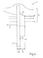
- Fig. 4 shows a side view of a stirring body 3 in the form of a weld bead.
- the stirring body 3 is hereby moved in the stirring direction 5, wherein schematically the flow pattern 41 in the form of drawn streamlines is shown in fragmentary form.
- the flow pattern 41 shown here represents only a sketch of a possible flow scenario, since the flow behavior of fluids around solids is essentially influenced by the rate of movement of the solid on the one hand and by the fluid mechanical properties, for example the viscosity of the fluid medium. In this case, both laminar, rather unfavorable for a stirring flow conditions as well as turbulent or even chaotic flow patterns can arise.
- the stirring body 3 has a thickness of the flat body 42a, which in the present case is somewhat smaller compared to the thickness of the flange 42.
- the flare is connected at its flanging edge steadily passing over the flare 43 to the flat element 6, wherein the Forming the hemming radius 43 seen either from a surface portion of the flat element 6 or, as not shown here, also from the edge of the flat element 6, with the aid of an elongated and possibly not purely circular radius, may be formed.
- a stirring body 3 is realized, which has almost no undercuts or depressions, which would represent, for example, for deposits in the form of impurities or difficulties in cleaning the device, for example in use in the food industry.
Landscapes
- Chemical & Material Sciences (AREA)
- Chemical Kinetics & Catalysis (AREA)
- Mixers Of The Rotary Stirring Type (AREA)
Priority Applications (1)
| Application Number | Priority Date | Filing Date | Title |
|---|---|---|---|
| PL09799550T PL2370198T3 (pl) | 2008-12-30 | 2009-12-23 | Mieszadło z wywiniętymi kołnierzami |
Applications Claiming Priority (2)
| Application Number | Priority Date | Filing Date | Title |
|---|---|---|---|
| DE102008063393A DE102008063393B3 (de) | 2008-12-30 | 2008-12-30 | Bördelrührer |
| PCT/EP2009/009248 WO2010076000A1 (de) | 2008-12-30 | 2009-12-23 | Bördelrührer |
Publications (2)
| Publication Number | Publication Date |
|---|---|
| EP2370198A1 EP2370198A1 (de) | 2011-10-05 |
| EP2370198B1 true EP2370198B1 (de) | 2013-11-20 |
Family
ID=42027930
Family Applications (1)
| Application Number | Title | Priority Date | Filing Date |
|---|---|---|---|
| EP09799550.0A Active EP2370198B1 (de) | 2008-12-30 | 2009-12-23 | Bördelrührer |
Country Status (6)
| Country | Link |
|---|---|
| US (1) | US20110249529A1 (pl) |
| EP (1) | EP2370198B1 (pl) |
| CN (1) | CN102271794B (pl) |
| DE (1) | DE102008063393B3 (pl) |
| PL (1) | PL2370198T3 (pl) |
| WO (1) | WO2010076000A1 (pl) |
Families Citing this family (11)
| Publication number | Priority date | Publication date | Assignee | Title |
|---|---|---|---|---|
| WO2015095260A1 (en) | 2013-12-17 | 2015-06-25 | Bayer Cropscience Lp | Mixing systems, methods, and devices with extendible impellers |
| US8876369B1 (en) * | 2014-03-24 | 2014-11-04 | Compatible Components Corporation | Apparatus for mixing liquids and/or solids with liquids |
| DE102015210904B4 (de) * | 2015-03-11 | 2018-03-15 | Protechna S.A. | Rührstabanordnung sowie Transport- und Lagerbehälter für Flüssigkeiten mit einer Rührstabanordnung |
| GB2528775B (en) * | 2015-06-19 | 2016-07-20 | Merchant Courtenay | Mixing device |
| DE102015011967A1 (de) * | 2015-09-18 | 2017-03-23 | Protechna S.A. | Rührorgan, Rührstabanordnung sowie Transport- und Lagerbehälter für Flüssigkeiten mit einer Rührstabanordnung |
| CN106079883A (zh) * | 2016-06-17 | 2016-11-09 | 胡俊 | 一种印刷油墨旋转搅拌机构 |
| DE102016114735A1 (de) | 2016-08-09 | 2018-02-15 | Mut Tschamber Misch- Und Trenntechnik Gmbh | Rührwerkzeug |
| RU182466U1 (ru) * | 2017-06-06 | 2018-08-20 | Юрий Владимирович Храмов | Устройство для смешивания жидких сред |
| FR3068618B1 (fr) * | 2017-07-10 | 2022-01-28 | Fillon Technologies | Dispositif d'agitation de fluide equipe d'un tel dispositif d'agitation |
| US11000814B1 (en) * | 2018-11-19 | 2021-05-11 | Donald Wynn, Sr. | Mixing apparatus with shafts of different lengths having circular members |
| WO2021192802A1 (ja) * | 2020-03-26 | 2021-09-30 | 富士フイルム株式会社 | 感放射線性樹脂組成物の製造方法、パターン形成方法 |
Citations (3)
| Publication number | Priority date | Publication date | Assignee | Title |
|---|---|---|---|---|
| SU1542601A1 (ru) * | 1987-09-18 | 1990-02-15 | Предприятие П/Я Р-6956 | Рамна мешалка |
| EP0622112A1 (en) * | 1993-04-30 | 1994-11-02 | Kansai Chemical Engineering Co. Ltd | An agitator blade |
| US20080094938A1 (en) * | 2006-10-24 | 2008-04-24 | Better Way Tool Company L.L.C. | Mixing lid having inner and outer paddles for mixing a liquid mixture in a container |
Family Cites Families (33)
| Publication number | Priority date | Publication date | Assignee | Title |
|---|---|---|---|---|
| US232717A (en) * | 1880-09-28 | Churn | ||
| US122075A (en) * | 1871-12-19 | Improvement in churn-dashers | ||
| US614138A (en) * | 1898-11-15 | Churn-dasher | ||
| US273569A (en) * | 1883-03-06 | Oearles marchand | ||
| US169835A (en) * | 1875-11-09 | Improvement in rotary churns | ||
| US628073A (en) * | 1898-10-26 | 1899-07-04 | Richard O Connor | Dough-mixer. |
| US950152A (en) * | 1909-06-09 | 1910-02-22 | William J C Gaar | Churn. |
| US1010019A (en) * | 1911-01-18 | 1911-11-28 | Mc Gill Mfg Co | Beater. |
| US1284816A (en) * | 1918-04-15 | 1918-11-12 | Norman R Thompson | Container-contents-handling mechanism. |
| US2213497A (en) * | 1938-06-21 | 1940-09-03 | William H Kelly | Airplane propeller |
| US2196983A (en) * | 1939-01-03 | 1940-04-16 | Du Pont | Mixing apparatus |
| US3158359A (en) * | 1963-01-09 | 1964-11-24 | Hugh A Stiffler | Dispersal vane |
| US3697053A (en) * | 1971-05-10 | 1972-10-10 | Michael J Will | Stirring device |
| DE3332069A1 (de) * | 1983-09-06 | 1985-03-21 | Hoechst Ag | Ruehrer fuer wandnahes ruehren |
| US4750864A (en) * | 1986-04-28 | 1988-06-14 | Carrier Corporation | Compressor lubrication and noise reduction system |
| CH675215A5 (pl) * | 1988-02-08 | 1990-09-14 | Kurt Walter Wyss | |
| US4848918A (en) * | 1988-08-04 | 1989-07-18 | Cf Systems Corporation | Mixing apparatus |
| US4936688A (en) * | 1988-11-14 | 1990-06-26 | Cornell Kathy M | Food stirring apparatus |
| US5090816A (en) * | 1989-02-09 | 1992-02-25 | Thomas Socha | Fluid mixing device |
| DE69122333T2 (de) * | 1990-08-07 | 1997-02-06 | Shinko Pantec Co Ltd | Mischapparat |
| US5516208A (en) * | 1995-03-27 | 1996-05-14 | Givant; Madeline F. | Adjustable pot stirrer |
| DE19711019A1 (de) | 1997-03-17 | 1998-09-24 | Basf Ag | Rührer mit variabel einstellbaren Rührorganen für Polymerisationsreaktoren |
| DE19743923C2 (de) * | 1997-10-04 | 2000-06-15 | Loedige Maschbau Gmbh Geb | Mischwerkzeug |
| JP3632827B2 (ja) * | 1998-11-11 | 2005-03-23 | リンテック株式会社 | 撹拌装置 |
| US6113258A (en) * | 1999-06-29 | 2000-09-05 | Ardent; John Craig | Battery powered food stirrer with pivotally mounted spring biased arms |
| DE20019941U1 (de) * | 2000-11-23 | 2001-02-22 | INOTEC GmbH Transport- und Fördersysteme, 79761 Waldshut-Tiengen | Vorrichtung zum Rühren eines strömungsfähigen oder rieselfähigen Mediums, insbesondere eines hochviskosen Mediums |
| DE10110910C1 (de) | 2001-03-07 | 2002-11-14 | Berents Gmbh & Co Kg A | Mischer zum Herstellen pastöser Produkte wie Salben, Cremes und Emulsionen |
| DE20116967U1 (de) * | 2001-10-16 | 2002-01-03 | Turbo-Misch- und Rühranlagen GmbH & Co. KG, 82024 Taufkirchen | Rührkörper |
| US7578611B2 (en) * | 2005-10-14 | 2009-08-25 | Ralph Hamilton | Stirrer tool with radially and distally extending flexible projections |
| US7484879B2 (en) * | 2005-10-14 | 2009-02-03 | Hamilton Jr Ralph H | Stirrer tool with radially and distally extending flexible projections |
| US7665886B2 (en) * | 2006-02-02 | 2010-02-23 | Morris Jr Joseph E | Nozzle device used for multiphase fluid flow simulation in high temperature and pressurized mixing reactors |
| US7665887B2 (en) * | 2006-02-02 | 2010-02-23 | Morris Jr Joseph E | Nozzle device with flow restrictors used for multiphase fluid flow simulation in high temperature and pressurized mixing reactors |
| CN101749180B (zh) * | 2008-12-02 | 2012-02-01 | 叶东华 | 垂直轴式风力发电机的叶片 |
-
2008
- 2008-12-30 DE DE102008063393A patent/DE102008063393B3/de active Active
-
2009
- 2009-12-23 EP EP09799550.0A patent/EP2370198B1/de active Active
- 2009-12-23 US US13/139,945 patent/US20110249529A1/en not_active Abandoned
- 2009-12-23 PL PL09799550T patent/PL2370198T3/pl unknown
- 2009-12-23 WO PCT/EP2009/009248 patent/WO2010076000A1/de not_active Ceased
- 2009-12-23 CN CN200980153822.0A patent/CN102271794B/zh active Active
Patent Citations (3)
| Publication number | Priority date | Publication date | Assignee | Title |
|---|---|---|---|---|
| SU1542601A1 (ru) * | 1987-09-18 | 1990-02-15 | Предприятие П/Я Р-6956 | Рамна мешалка |
| EP0622112A1 (en) * | 1993-04-30 | 1994-11-02 | Kansai Chemical Engineering Co. Ltd | An agitator blade |
| US20080094938A1 (en) * | 2006-10-24 | 2008-04-24 | Better Way Tool Company L.L.C. | Mixing lid having inner and outer paddles for mixing a liquid mixture in a container |
Also Published As
| Publication number | Publication date |
|---|---|
| CN102271794B (zh) | 2016-05-11 |
| DE102008063393B3 (de) | 2010-06-02 |
| PL2370198T3 (pl) | 2014-04-30 |
| WO2010076000A1 (de) | 2010-07-08 |
| EP2370198A1 (de) | 2011-10-05 |
| CN102271794A (zh) | 2011-12-07 |
| US20110249529A1 (en) | 2011-10-13 |
Similar Documents
| Publication | Publication Date | Title |
|---|---|---|
| DE102008063393B3 (de) | Bördelrührer | |
| EP1471993B1 (de) | Dispergier-vorrichtung | |
| DE3901894A1 (de) | Vorrichtung zum mischen von stroemungsfaehigen, insbesondere pastoesen medien sowie verfahren zu deren betrieb | |
| EP2819774B1 (de) | Vorrichtung zum mischen mindestens zweier fluider komponenten, drehangetriebener mischereinsatz dafür und system aus beidem | |
| EP3498365B1 (de) | Rührorganvorrichtung | |
| EP1925358B1 (de) | Rührwerkzeug zur Herstellung eines flüssigen Gemischs aus wenigstens zwei Komponenten, sowie die Verwendung des Rührwerkzeugs | |
| DE69724400T2 (de) | Vorrichtung mit kontrolliertem Abgabemuster | |
| DE202014002901U1 (de) | Klappmischer | |
| DE2643560C2 (de) | Rührvorrichtung | |
| DE69401414T2 (de) | Einheitlicher, einstückiger, drehbarer Mischer und Abgabekopf | |
| DE1557230B2 (de) | Rührteil für einen Magnetrührer | |
| EP3482821B1 (de) | Rührwerk | |
| EP0761296B1 (de) | Abstreifvorrichtung | |
| DE102008005017B3 (de) | Rührorgan und Rührwerk zum Mischen und/oder Homogenisieren strömungsfähiger Medien | |
| EP2158960A1 (de) | Verfahren zum Mischen eines in einem Mischbehälter befindlichen Mischgutes sowie Mischvorrichtung | |
| DE102011015316B4 (de) | Rührwerk zum Mischen und/oder Homogenisieren strömungsfähiger Medien | |
| DE202012002102U1 (de) | Vorrichtung zum Mischen mindestens zweier fluider Komponenten, drehangetriebener Mischereinsatz dafür und System aus beidem | |
| WO2003033124A1 (de) | Rührkörper | |
| DE102008005018B3 (de) | Rührorgan und Rührwerk zum Mischen und/oder Homogenisieren strömungsfähiger Medien | |
| DE102005003528A1 (de) | Rührvorrichtung | |
| DE102010049034B4 (de) | Rührorgan und Rührwerk zum Mischen und/oder Homogenisieren strömungsfähiger Medien | |
| EP3639915B1 (de) | Mehrebiges rührorgan | |
| DE202005008676U1 (de) | Rührvorrichtung | |
| EP2764909A2 (de) | Mischvorrichtung für Zweikomponentenkartuschen | |
| DE10161180B4 (de) | Mischvorrichtung zum Mischen von mindestens zwei flüssigen Komponenten |
Legal Events
| Date | Code | Title | Description |
|---|---|---|---|
| PUAI | Public reference made under article 153(3) epc to a published international application that has entered the european phase |
Free format text: ORIGINAL CODE: 0009012 |
|
| 17P | Request for examination filed |
Effective date: 20110604 |
|
| AK | Designated contracting states |
Kind code of ref document: A1 Designated state(s): AT BE BG CH CY CZ DE DK EE ES FI FR GB GR HR HU IE IS IT LI LT LU LV MC MK MT NL NO PL PT RO SE SI SK SM TR |
|
| DAX | Request for extension of the european patent (deleted) | ||
| 17Q | First examination report despatched |
Effective date: 20120525 |
|
| GRAP | Despatch of communication of intention to grant a patent |
Free format text: ORIGINAL CODE: EPIDOSNIGR1 |
|
| INTG | Intention to grant announced |
Effective date: 20130626 |
|
| GRAS | Grant fee paid |
Free format text: ORIGINAL CODE: EPIDOSNIGR3 |
|
| GRAA | (expected) grant |
Free format text: ORIGINAL CODE: 0009210 |
|
| RBV | Designated contracting states (corrected) |
Designated state(s): AT BE BG CH CY CZ DK EE ES FI FR GB GR HR HU IE IS IT LI LT LU LV MC MK MT NL NO PL PT RO SE SI SK SM TR |
|
| REG | Reference to a national code |
Ref country code: DE Ref legal event code: R108 |
|
| AK | Designated contracting states |
Kind code of ref document: B1 Designated state(s): AT BE BG CH CY CZ DK EE ES FI FR GB GR HR HU IE IS IT LI LT LU LV MC MK MT NL NO PL PT RO SE SI SK SM TR |
|
| REG | Reference to a national code |
Ref country code: GB Ref legal event code: FG4D Free format text: NOT ENGLISH |
|
| REG | Reference to a national code |
Ref country code: CH Ref legal event code: NV Representative=s name: ROTTMANN, ZIMMERMANN + PARTNER AG, CH Ref country code: CH Ref legal event code: EP |
|
| REG | Reference to a national code |
Ref country code: AT Ref legal event code: REF Ref document number: 641245 Country of ref document: AT Kind code of ref document: T Effective date: 20131215 |
|
| REG | Reference to a national code |
Ref country code: IE Ref legal event code: FG4D Free format text: LANGUAGE OF EP DOCUMENT: GERMAN |
|
| REG | Reference to a national code |
Ref country code: DE Ref legal event code: R108 Effective date: 20131106 |
|
| REG | Reference to a national code |
Ref country code: NL Ref legal event code: T3 |
|
| REG | Reference to a national code |
Ref country code: NL Ref legal event code: T3 |
|
| REG | Reference to a national code |
Ref country code: LT Ref legal event code: MG4D |
|
| PG25 | Lapsed in a contracting state [announced via postgrant information from national office to epo] |
Ref country code: IS Free format text: LAPSE BECAUSE OF FAILURE TO SUBMIT A TRANSLATION OF THE DESCRIPTION OR TO PAY THE FEE WITHIN THE PRESCRIBED TIME-LIMIT Effective date: 20140320 Ref country code: SE Free format text: LAPSE BECAUSE OF FAILURE TO SUBMIT A TRANSLATION OF THE DESCRIPTION OR TO PAY THE FEE WITHIN THE PRESCRIBED TIME-LIMIT Effective date: 20131120 Ref country code: HR Free format text: LAPSE BECAUSE OF FAILURE TO SUBMIT A TRANSLATION OF THE DESCRIPTION OR TO PAY THE FEE WITHIN THE PRESCRIBED TIME-LIMIT Effective date: 20131120 Ref country code: FI Free format text: LAPSE BECAUSE OF FAILURE TO SUBMIT A TRANSLATION OF THE DESCRIPTION OR TO PAY THE FEE WITHIN THE PRESCRIBED TIME-LIMIT Effective date: 20131120 Ref country code: LT Free format text: LAPSE BECAUSE OF FAILURE TO SUBMIT A TRANSLATION OF THE DESCRIPTION OR TO PAY THE FEE WITHIN THE PRESCRIBED TIME-LIMIT Effective date: 20131120 Ref country code: NO Free format text: LAPSE BECAUSE OF FAILURE TO SUBMIT A TRANSLATION OF THE DESCRIPTION OR TO PAY THE FEE WITHIN THE PRESCRIBED TIME-LIMIT Effective date: 20140220 |
|
| REG | Reference to a national code |
Ref country code: PL Ref legal event code: T3 |
|
| PG25 | Lapsed in a contracting state [announced via postgrant information from national office to epo] |
Ref country code: LV Free format text: LAPSE BECAUSE OF FAILURE TO SUBMIT A TRANSLATION OF THE DESCRIPTION OR TO PAY THE FEE WITHIN THE PRESCRIBED TIME-LIMIT Effective date: 20131120 Ref country code: ES Free format text: LAPSE BECAUSE OF FAILURE TO SUBMIT A TRANSLATION OF THE DESCRIPTION OR TO PAY THE FEE WITHIN THE PRESCRIBED TIME-LIMIT Effective date: 20131120 |
|
| PG25 | Lapsed in a contracting state [announced via postgrant information from national office to epo] |
Ref country code: PT Free format text: LAPSE BECAUSE OF FAILURE TO SUBMIT A TRANSLATION OF THE DESCRIPTION OR TO PAY THE FEE WITHIN THE PRESCRIBED TIME-LIMIT Effective date: 20140320 |
|
| PG25 | Lapsed in a contracting state [announced via postgrant information from national office to epo] |
Ref country code: EE Free format text: LAPSE BECAUSE OF FAILURE TO SUBMIT A TRANSLATION OF THE DESCRIPTION OR TO PAY THE FEE WITHIN THE PRESCRIBED TIME-LIMIT Effective date: 20131120 |
|
| PG25 | Lapsed in a contracting state [announced via postgrant information from national office to epo] |
Ref country code: SK Free format text: LAPSE BECAUSE OF FAILURE TO SUBMIT A TRANSLATION OF THE DESCRIPTION OR TO PAY THE FEE WITHIN THE PRESCRIBED TIME-LIMIT Effective date: 20131120 Ref country code: RO Free format text: LAPSE BECAUSE OF FAILURE TO SUBMIT A TRANSLATION OF THE DESCRIPTION OR TO PAY THE FEE WITHIN THE PRESCRIBED TIME-LIMIT Effective date: 20131120 |
|
| REG | Reference to a national code |
Ref country code: IE Ref legal event code: MM4A |
|
| PLBE | No opposition filed within time limit |
Free format text: ORIGINAL CODE: 0009261 |
|
| STAA | Information on the status of an ep patent application or granted ep patent |
Free format text: STATUS: NO OPPOSITION FILED WITHIN TIME LIMIT |
|
| PG25 | Lapsed in a contracting state [announced via postgrant information from national office to epo] |
Ref country code: DK Free format text: LAPSE BECAUSE OF FAILURE TO SUBMIT A TRANSLATION OF THE DESCRIPTION OR TO PAY THE FEE WITHIN THE PRESCRIBED TIME-LIMIT Effective date: 20131120 |
|
| 26N | No opposition filed |
Effective date: 20140821 |
|
| PG25 | Lapsed in a contracting state [announced via postgrant information from national office to epo] |
Ref country code: IE Free format text: LAPSE BECAUSE OF NON-PAYMENT OF DUE FEES Effective date: 20131223 |
|
| PG25 | Lapsed in a contracting state [announced via postgrant information from national office to epo] |
Ref country code: SI Free format text: LAPSE BECAUSE OF FAILURE TO SUBMIT A TRANSLATION OF THE DESCRIPTION OR TO PAY THE FEE WITHIN THE PRESCRIBED TIME-LIMIT Effective date: 20131120 |
|
| PG25 | Lapsed in a contracting state [announced via postgrant information from national office to epo] |
Ref country code: MC Free format text: LAPSE BECAUSE OF FAILURE TO SUBMIT A TRANSLATION OF THE DESCRIPTION OR TO PAY THE FEE WITHIN THE PRESCRIBED TIME-LIMIT Effective date: 20131120 |
|
| PG25 | Lapsed in a contracting state [announced via postgrant information from national office to epo] |
Ref country code: SM Free format text: LAPSE BECAUSE OF FAILURE TO SUBMIT A TRANSLATION OF THE DESCRIPTION OR TO PAY THE FEE WITHIN THE PRESCRIBED TIME-LIMIT Effective date: 20131120 |
|
| PG25 | Lapsed in a contracting state [announced via postgrant information from national office to epo] |
Ref country code: CY Free format text: LAPSE BECAUSE OF FAILURE TO SUBMIT A TRANSLATION OF THE DESCRIPTION OR TO PAY THE FEE WITHIN THE PRESCRIBED TIME-LIMIT Effective date: 20131120 |
|
| PG25 | Lapsed in a contracting state [announced via postgrant information from national office to epo] |
Ref country code: HU Free format text: LAPSE BECAUSE OF FAILURE TO SUBMIT A TRANSLATION OF THE DESCRIPTION OR TO PAY THE FEE WITHIN THE PRESCRIBED TIME-LIMIT; INVALID AB INITIO Effective date: 20091223 Ref country code: MK Free format text: LAPSE BECAUSE OF FAILURE TO SUBMIT A TRANSLATION OF THE DESCRIPTION OR TO PAY THE FEE WITHIN THE PRESCRIBED TIME-LIMIT Effective date: 20131120 Ref country code: BG Free format text: LAPSE BECAUSE OF FAILURE TO SUBMIT A TRANSLATION OF THE DESCRIPTION OR TO PAY THE FEE WITHIN THE PRESCRIBED TIME-LIMIT Effective date: 20131120 Ref country code: LU Free format text: LAPSE BECAUSE OF NON-PAYMENT OF DUE FEES Effective date: 20131223 |
|
| PG25 | Lapsed in a contracting state [announced via postgrant information from national office to epo] |
Ref country code: MT Free format text: LAPSE BECAUSE OF FAILURE TO SUBMIT A TRANSLATION OF THE DESCRIPTION OR TO PAY THE FEE WITHIN THE PRESCRIBED TIME-LIMIT Effective date: 20131120 Ref country code: GR Free format text: LAPSE BECAUSE OF NON-PAYMENT OF DUE FEES Effective date: 20131120 |
|
| REG | Reference to a national code |
Ref country code: FR Ref legal event code: PLFP Year of fee payment: 7 |
|
| PG25 | Lapsed in a contracting state [announced via postgrant information from national office to epo] |
Ref country code: GR Free format text: LAPSE BECAUSE OF FAILURE TO SUBMIT A TRANSLATION OF THE DESCRIPTION OR TO PAY THE FEE WITHIN THE PRESCRIBED TIME-LIMIT Effective date: 20140221 |
|
| REG | Reference to a national code |
Ref country code: CH Ref legal event code: PCAR Free format text: NEW ADDRESS: GARTENSTRASSE 28 A, 5400 BADEN (CH) |
|
| REG | Reference to a national code |
Ref country code: FR Ref legal event code: PLFP Year of fee payment: 8 |
|
| REG | Reference to a national code |
Ref country code: FR Ref legal event code: PLFP Year of fee payment: 9 |
|
| PGFP | Annual fee paid to national office [announced via postgrant information from national office to epo] |
Ref country code: GB Payment date: 20201222 Year of fee payment: 12 Ref country code: FR Payment date: 20201218 Year of fee payment: 12 |
|
| PGFP | Annual fee paid to national office [announced via postgrant information from national office to epo] |
Ref country code: BE Payment date: 20201217 Year of fee payment: 12 |
|
| PGFP | Annual fee paid to national office [announced via postgrant information from national office to epo] |
Ref country code: IT Payment date: 20201230 Year of fee payment: 12 |
|
| GBPC | Gb: european patent ceased through non-payment of renewal fee |
Effective date: 20211223 |
|
| REG | Reference to a national code |
Ref country code: BE Ref legal event code: MM Effective date: 20211231 |
|
| PG25 | Lapsed in a contracting state [announced via postgrant information from national office to epo] |
Ref country code: GB Free format text: LAPSE BECAUSE OF NON-PAYMENT OF DUE FEES Effective date: 20211223 |
|
| PG25 | Lapsed in a contracting state [announced via postgrant information from national office to epo] |
Ref country code: FR Free format text: LAPSE BECAUSE OF NON-PAYMENT OF DUE FEES Effective date: 20211231 Ref country code: BE Free format text: LAPSE BECAUSE OF NON-PAYMENT OF DUE FEES Effective date: 20211231 |
|
| PGFP | Annual fee paid to national office [announced via postgrant information from national office to epo] |
Ref country code: PL Payment date: 20220928 Year of fee payment: 14 |
|
| PG25 | Lapsed in a contracting state [announced via postgrant information from national office to epo] |
Ref country code: IT Free format text: LAPSE BECAUSE OF NON-PAYMENT OF DUE FEES Effective date: 20211223 |
|
| PGFP | Annual fee paid to national office [announced via postgrant information from national office to epo] |
Ref country code: NL Payment date: 20221220 Year of fee payment: 14 Ref country code: CZ Payment date: 20221212 Year of fee payment: 14 Ref country code: AT Payment date: 20221216 Year of fee payment: 14 |
|
| PGFP | Annual fee paid to national office [announced via postgrant information from national office to epo] |
Ref country code: TR Payment date: 20221223 Year of fee payment: 14 |
|
| PG25 | Lapsed in a contracting state [announced via postgrant information from national office to epo] |
Ref country code: CZ Free format text: LAPSE BECAUSE OF NON-PAYMENT OF DUE FEES Effective date: 20231223 |
|
| PG25 | Lapsed in a contracting state [announced via postgrant information from national office to epo] |
Ref country code: CZ Free format text: LAPSE BECAUSE OF NON-PAYMENT OF DUE FEES Effective date: 20231223 |
|
| REG | Reference to a national code |
Ref country code: NL Ref legal event code: MM Effective date: 20240101 |
|
| REG | Reference to a national code |
Ref country code: AT Ref legal event code: MM01 Ref document number: 641245 Country of ref document: AT Kind code of ref document: T Effective date: 20231223 |
|
| PG25 | Lapsed in a contracting state [announced via postgrant information from national office to epo] |
Ref country code: NL Free format text: LAPSE BECAUSE OF NON-PAYMENT OF DUE FEES Effective date: 20240101 |
|
| PG25 | Lapsed in a contracting state [announced via postgrant information from national office to epo] |
Ref country code: NL Free format text: LAPSE BECAUSE OF NON-PAYMENT OF DUE FEES Effective date: 20240101 |
|
| PG25 | Lapsed in a contracting state [announced via postgrant information from national office to epo] |
Ref country code: AT Free format text: LAPSE BECAUSE OF NON-PAYMENT OF DUE FEES Effective date: 20231223 |
|
| PG25 | Lapsed in a contracting state [announced via postgrant information from national office to epo] |
Ref country code: AT Free format text: LAPSE BECAUSE OF NON-PAYMENT OF DUE FEES Effective date: 20231223 |
|
| PG25 | Lapsed in a contracting state [announced via postgrant information from national office to epo] |
Ref country code: PL Free format text: LAPSE BECAUSE OF NON-PAYMENT OF DUE FEES Effective date: 20231223 |
|
| REG | Reference to a national code |
Ref country code: CH Ref legal event code: U11 Free format text: ST27 STATUS EVENT CODE: U-0-0-U10-U11 (AS PROVIDED BY THE NATIONAL OFFICE) Effective date: 20260101 |
|
| REG | Reference to a national code |
Ref country code: CH Ref legal event code: R17 Free format text: ST27 STATUS EVENT CODE: U-0-0-R10-R17 (AS PROVIDED BY THE NATIONAL OFFICE) Effective date: 20260410 |
|
| PGFP | Annual fee paid to national office [announced via postgrant information from national office to epo] |
Ref country code: CH Payment date: 20260101 Year of fee payment: 17 |