EP2369709A2 - Lastschalter mit Sicherungen mit Steuerungsmanagement für Solarzellen - Google Patents
Lastschalter mit Sicherungen mit Steuerungsmanagement für Solarzellen Download PDFInfo
- Publication number
- EP2369709A2 EP2369709A2 EP11168783A EP11168783A EP2369709A2 EP 2369709 A2 EP2369709 A2 EP 2369709A2 EP 11168783 A EP11168783 A EP 11168783A EP 11168783 A EP11168783 A EP 11168783A EP 2369709 A2 EP2369709 A2 EP 2369709A2
- Authority
- EP
- European Patent Office
- Prior art keywords
- string
- controller
- mechanical switch
- voltage
- solar
- Prior art date
- Legal status (The legal status is an assumption and is not a legal conclusion. Google has not performed a legal analysis and makes no representation as to the accuracy of the status listed.)
- Granted
Links
- 238000013523 data management Methods 0.000 claims description 33
- 230000002441 reversible effect Effects 0.000 claims description 21
- 238000000034 method Methods 0.000 claims description 15
- 239000004065 semiconductor Substances 0.000 claims description 15
- 230000008859 change Effects 0.000 claims description 14
- 238000012546 transfer Methods 0.000 claims description 10
- 238000005259 measurement Methods 0.000 claims description 7
- 230000000694 effects Effects 0.000 claims description 6
- 230000007257 malfunction Effects 0.000 description 17
- 238000010586 diagram Methods 0.000 description 16
- 230000006378 damage Effects 0.000 description 9
- 238000012423 maintenance Methods 0.000 description 9
- 238000012544 monitoring process Methods 0.000 description 8
- 230000008901 benefit Effects 0.000 description 7
- 230000005855 radiation Effects 0.000 description 7
- 238000001514 detection method Methods 0.000 description 6
- 238000007726 management method Methods 0.000 description 5
- 230000008878 coupling Effects 0.000 description 4
- 238000010168 coupling process Methods 0.000 description 4
- 238000005859 coupling reaction Methods 0.000 description 4
- 230000008569 process Effects 0.000 description 4
- 238000004458 analytical method Methods 0.000 description 3
- 230000033228 biological regulation Effects 0.000 description 3
- 230000007547 defect Effects 0.000 description 3
- 230000007613 environmental effect Effects 0.000 description 3
- 230000003628 erosive effect Effects 0.000 description 3
- 238000002844 melting Methods 0.000 description 3
- 230000008018 melting Effects 0.000 description 3
- 230000003287 optical effect Effects 0.000 description 3
- 238000010420 art technique Methods 0.000 description 2
- 230000007797 corrosion Effects 0.000 description 2
- 238000005260 corrosion Methods 0.000 description 2
- 230000003247 decreasing effect Effects 0.000 description 2
- 230000001965 increasing effect Effects 0.000 description 2
- 238000009434 installation Methods 0.000 description 2
- 238000000926 separation method Methods 0.000 description 2
- 206010061218 Inflammation Diseases 0.000 description 1
- 230000005856 abnormality Effects 0.000 description 1
- 230000002411 adverse Effects 0.000 description 1
- 230000032683 aging Effects 0.000 description 1
- 230000015572 biosynthetic process Effects 0.000 description 1
- 238000004891 communication Methods 0.000 description 1
- 230000001419 dependent effect Effects 0.000 description 1
- 230000005611 electricity Effects 0.000 description 1
- 238000005516 engineering process Methods 0.000 description 1
- 238000007667 floating Methods 0.000 description 1
- 230000004907 flux Effects 0.000 description 1
- 238000002847 impedance measurement Methods 0.000 description 1
- 230000001939 inductive effect Effects 0.000 description 1
- 230000004054 inflammatory process Effects 0.000 description 1
- 230000001788 irregular Effects 0.000 description 1
- 230000007774 longterm Effects 0.000 description 1
- 230000007246 mechanism Effects 0.000 description 1
- 238000012986 modification Methods 0.000 description 1
- 230000004048 modification Effects 0.000 description 1
- 230000002829 reductive effect Effects 0.000 description 1
- 230000003685 thermal hair damage Effects 0.000 description 1
- 239000010409 thin film Substances 0.000 description 1
Images


Classifications
-
- H—ELECTRICITY
- H02—GENERATION; CONVERSION OR DISTRIBUTION OF ELECTRIC POWER
- H02H—EMERGENCY PROTECTIVE CIRCUIT ARRANGEMENTS
- H02H5/00—Emergency protective circuit arrangements for automatic disconnection directly responsive to an undesired change from normal non-electric working conditions with or without subsequent reconnection
- H02H5/10—Emergency protective circuit arrangements for automatic disconnection directly responsive to an undesired change from normal non-electric working conditions with or without subsequent reconnection responsive to mechanical injury, e.g. rupture of line, breakage of earth connection
-
- G—PHYSICS
- G08—SIGNALLING
- G08B—SIGNALLING OR CALLING SYSTEMS; ORDER TELEGRAPHS; ALARM SYSTEMS
- G08B13/00—Burglar, theft or intruder alarms
- G08B13/02—Mechanical actuation
- G08B13/14—Mechanical actuation by lifting or attempted removal of hand-portable articles
- G08B13/1409—Mechanical actuation by lifting or attempted removal of hand-portable articles for removal detection of electrical appliances by detecting their physical disconnection from an electrical system, e.g. using a switch incorporated in the plug connector
- G08B13/1418—Removal detected by failure in electrical connection between the appliance and a control centre, home control panel or a power supply
-
- H—ELECTRICITY
- H02—GENERATION; CONVERSION OR DISTRIBUTION OF ELECTRIC POWER
- H02S—GENERATION OF ELECTRIC POWER BY CONVERSION OF INFRARED RADIATION, VISIBLE LIGHT OR ULTRAVIOLET LIGHT, e.g. USING PHOTOVOLTAIC [PV] MODULES
- H02S50/00—Monitoring or testing of PV systems, e.g. load balancing or fault identification
-
- Y—GENERAL TAGGING OF NEW TECHNOLOGICAL DEVELOPMENTS; GENERAL TAGGING OF CROSS-SECTIONAL TECHNOLOGIES SPANNING OVER SEVERAL SECTIONS OF THE IPC; TECHNICAL SUBJECTS COVERED BY FORMER USPC CROSS-REFERENCE ART COLLECTIONS [XRACs] AND DIGESTS
- Y02—TECHNOLOGIES OR APPLICATIONS FOR MITIGATION OR ADAPTATION AGAINST CLIMATE CHANGE
- Y02E—REDUCTION OF GREENHOUSE GAS [GHG] EMISSIONS, RELATED TO ENERGY GENERATION, TRANSMISSION OR DISTRIBUTION
- Y02E10/00—Energy generation through renewable energy sources
- Y02E10/50—Photovoltaic [PV] energy
- Y02E10/56—Power conversion systems, e.g. maximum power point trackers
Definitions
- the invention generally relates to solar modules and the control of such solar modules. More specifically, the invention relates to power and data management of such solar modules and the protection of such solar modules and a load connected to such solar modules against abnormalities in operation.
- a solar power generator usually comprises a number of solar modules.
- a solar module usually comprises a plurality of solar cells. The solar modules are connected in series to form a string of solar modules. The number of solar modules connected to form such a string is limited due to the maximum voltage which can be safely handled. Today, the maximum voltage supplied by a string is usually set to 1kV.
- a novel regulation is expected for the European Community and probably other countries to issue soon, defining certain safety regulations for solar power generators connected to the public mains. This regulation will prescribe a safe separation of the solar generator from the mains to avoid interference.
- string is used to define a string comprising a number of solar modules or a single solar module.
- a further problem associated with such solar generators comprising a plurality of strings is to avoid a damage of one solar module, solar cell or string if another solar module, solar cell or string of the generator has a malfunction. Such malfunction may result in reverse currents which may heavily negatively affect the other solar modules, cells or strings of the generator.
- DE 100 02 870 A1 describes an electrical circuit to limit the current in an electrical line.
- the circuit comprises a vacuum switch controlled by an over-current detection logic which is coupled to the monitored electrical line.
- This prior art system cannot provide protection against reverse currents and thus is not suitable for use in solar generators comprising a plurality of solar cells.
- EP 1 014 403 A1 A further prior art system which may be used to limit the current flowing in an electrical line is disclosed in EP 1 014 403 A1 .
- This system is adapted to detect short circuit currents using a specific measuring and analyzing unit.
- this prior art system again does not provide any protection against reverse currents and thus is not suited to be used in solar generators comprising more than one solar module.
- EP 1 538 645 A1 discloses another electrical circuit for disrupting an electrical line the circuit being improved to decrease the electrical arc occurring in mechanical switches when they are opened or closed in high-voltage systems.
- the such disclosed prior art system has a number of drawbacks.
- the system comprises electrical components connected in series to the power line effecting significant losses. Further, the system is not adapted to react in cases of reverse currents.
- JP 200 2367 046 A describes an anti-theft device for a solar battery module comprising a cable for loop formation and an alarm control board connected with this loop.
- This system has the drawback that an additional circuit is required to provide theft protection.
- a further drawback lies in the fact, that the cable forming the loop may be bridged before interrupting it and thus a thief may overcome this system when being aware of its presence.
- WO 2004/090993 A2 discloses another method to protect a photovoltaic panel against theft.
- This prior art system has the drawback, that it is associated to a single string of solar modules and is able to detect the disconnection of this string. However, it is not possible to detect the disconnection of a single solar module from a string of modules. Further, the system is unsafe with regard to possible attempts to replace the stolen solar cell with a battery or the like.
- a further drawback of this prior art system is that a distinct analysis of a string of solar cells is only possible using a complex op-analysis with an oscillating signal when the string is disconnected from the electricity network. However, it is undesirable to repeatedly disconnect the solar generator from the public mains for the purpose of theft protection.
- Another problem associated in particular with large scale solar generators is the monitoring and controlling of the single strings forming the generator. It is necessary, for the purpose of maintenance and for providing a power output of the solar generator adapted to the actual need to provide an individual control of the strings and to achieve information about any malfunction in one of the strings.
- a further important problem associated with the assembling of strings is the danger of reverse connection of strings which might occur in the course of initial installation, maintenance or replacement of a string. This may largely affect the function of the whole system as a string which is reverse connected may damage other strings of the generator.
- the invention aims at providing a connection technique and circuit for solar generators which overcomes one or more of the above-referenced problems.
- the invention aims at providing a circuit which is capable to safely avoid any damage to the connected string itself resulting from any external interference as well as to other strings which are connected to this string.
- the invention aims at providing a circuit which is capable to safely avoid any negative effects in the public mains connected to a solar power generator due to malfunction of this solar power generator.
- an electrical circuit arrangement for controlling the output of at least one first string, the electrical circuit arrangement comprising:
- the invention provides an arrangement, wherein an advanced monitoring of a string is achieved and thus an improved control of the string can be carried out.
- the controller according to the invention is capable to handle malfunction of the string which may result in a voltage or current lying outside of the usual range of values supplied by the string. By this, the system is capable to provide safety against excessive currents as well as reverse currents.
- the mechanical switch may preferably be a relay.
- the measurement of the current may be performed via a shunt or as magnetic flux measurement.
- the voltage measurement may take place before and/or behind the mechanical switch or shunt.
- a first preferred embodiment comprises a second mechanical switch in the other of the connecting lines of the string, wherein the controller is adapted to simultaneously control the first and second mechanical switch. This allows a complete disconnection of the string from the public mains and the remaining strings of the solar generator in case of any malfunction.
- the controller is adapted to sequentially actuate the first and second mechanical switch shifted for a short time interval to reduce peak power.
- the controller is adapted to sequentially actuate the first and second mechanical switch shifted for a short time interval to reduce peak power.
- the second switch 50ms after the first mechanical switch to reduce peak power of the involved logic components.
- the limits of the predetermined range are programmable. This programming may take place in the controller itself or in a central power and data management control. It is a permanent problem of prior art technique that the safety limits have to be adapted to the specific individual properties of the individual solar generator arrangement which is installed. In the course of this, the maximum voltage limit must usually be set to the open-circuit voltage to protect the inverter from undue voltage. However this voltage limit will decrease significantly in actual operation of the solar generator and will usually only be reached at low temperature condition. Thus, according to the prior art, only a lower number of solar modules could be connected to an inverter having such a predetermined upper voltage limit than the inverter could handle at normal operation conditions.
- Using a programmable upper voltage limit will allow a safe protection of the inverter and a much easier dimensioning of the components of the solar generator.
- the respective strings may be separated by opening the switches or single solar modules out of this string may be separated and bridged to reduce the voltage to an acceptable level.
- the output voltage may be doubled due to serial connection of the solar modules.
- the maximum voltage limit may be increased respectively.
- the limits for the allowable currents provides the advantages, that the short cut current limits which are largely dependent from the incoming radiation may be programmed depending on the actual radiation. This will allow to provide a sensitive short cut protection in cases of high or low radiation.
- a further advantage is the easy adjustment of the controller to various types of solar modules.
- the reverse current allowable for a solar module depends on the type of module, e.g. polycrystalline solar modules may carry a reverse current which is round 4-times higher than solar modules based on thin film technique.
- the circuit arrangement according to the invention may thus easily be adapted to different solar generators by programming the limits or may be re-programmed if single or all solar modules of the generator are replaced with new solar modules having a different technology.
- the controller is adapted to program the limits using a real-time software programming, a predetermined firmware programming or a hardware programming using programmable hardware plugs or removable electronic components like hardware bridges, hardware switches or resistors.
- the limits may either be programmed when dimensioning the solar generator, which may easily be achieved using hardware or software programming. Further, it may be required to change the limits due to later modifications of the solar generator which may be achieved using hardware or software programming, too.
- the controller comprises a direct switch to actuate the mechanical switch.
- the controller is installed adjacent to the solar modules. In case of maintenance it is often preferred to manually deactivate or activate the mechanical switch in the connecting line.
- a direct switch is preferably installed at the controller. This will allow to safely disconnect a solar module for maintenance or in case of a defect which is of particular importance if the mechanical switches may be controlled from a distance. The direct switch will override this distance-control actuation in particular for off condition.
- the measuring device is arranged to measure the current via a shunt at low impedance.
- the measuring device is arranged to directly measure the output voltage of the string, i.e. to measure the voltage across the connecting lines between the string and the mechanical switch. This allows to directly detect any excessive voltage or reverse connection of the string.
- the controller is adapted to open the mechanical switch if the direct output voltage exceeds a certain limit or the solar module is reverse-connected.
- the mechanical switch will be opened immediately in case of such malfunction or will not be closed if already open.
- the measuring device is adapted to measure the output voltage of the electric circuit including the string and the mechanical switch, i.e. the voltage across the connecting lines between the mechanical switch and an inverter.
- This may be achieved by providing an additional measuring device and will allow to detect a short circuit of the power output lines, in particular a common bus-bar used to connect a plurality of strings and thus will allow to protect the string against any negative influence coming from the output side as well as vice versa even in case that the mechanical switch is in open position.
- This feature enables also a bus bar fusing in conjunction with the communication to all other controls to switch all strings off.
- string comprises at least two solar modules connected.
- the invention is particularly well-suited for large scale solar generators.
- the controller is adapted to output a status signal signalizing at least one of the operational characteristics like output voltage or current of the string. This will allow to monitor the status of the string from a distance to achieve a safe operation of large scale solar generators comprising a plurality of such strings.
- a further preferred embodiment of the invention comprises a plurality of solar strings and a central power and data management device connected to the controller of each of the strings for managing the power and data of the strings.
- This central power and data management device will allow to receive detailed information about the function or malfunction of single strings of the solar generator and thus will allow to optimize maintenance and replacement of defect solar modules in large scale generators. Further, this feature will also enables easy connection of monitoring systems.
- a direct switch of the central power and management control device to actuate the mechanical switches of a number of strings. This will provide the advantages as discussed above for a number of strings for the purpose of maintenance.
- the measuring device is adapted to measure the voltage of one or both of each of the connecting lines versus ground. This will improve the circuit arrangement in order to detect any ground loop occurring in the system and to allow to take the necessary steps when such ground loop is detected. It is preferred that the voltage of both connecting lines is measured versus ground so that any ground loops occurring on any side will be detected.
- Another important preferred embodiment of the invention is characterized by a semiconductor switch arranged to shortcut the connecting lines of the string between the mechanical switch and the inverter and further characterized by a control device adapted to close the semiconductor switch for the time period of opening or closing of the mechanical switch.
- a constant problem associated with mechanical switches used in high voltage circuits is the occurrence of an arc during opening and closing of the switch. This arc will induce an erosion process at each time of an opening or closing of the switch. The magnitude of erosion will depend on the current flowing via the arc. A plurality of such erosion processes will damage the contacts of the switch significantly and may result in failure of the switch. Further, the arc effects a temperature increase and thus implies the risk of thermal damage or even inflammation of the switch.
- the preferred embodiment overcomes these drawbacks in that during the process of opening or closing of the switch a semiconductor switch is closed which shortcuts the connecting lines of the string. Consequently the mechanical switch can be opened or closed at low current without the occurrence of a significant arc.
- the semiconductor switch may preferably be arranged between the connecting lines of the string itself or between the lines of a common bus-bar coupling a plurality of such strings. Shortcutting a string does not negatively effect the string or another string coupled with this string because of the characteristic of solar modules having a limited shortcut current and experiencing no damage when operated in short circuit.
- the use of such a semiconductor switch provides improved characteristics if the mechanical switch is opened in a system comprising a plurality of strings as the reverse current resulting from the sum of the other strings will, mainly contribute to otherwise damage the mechanical switch by exceeding the maximum power to be switched.
- controller is adapted to provided a theft control for a string connected to the circuit arrangement, the theft control comprising:
- the theft protection according to the invention overcomes the drawbacks of prior art theft protection systems as a simple but safe control of the current is performed which may easily detect any irregular sudden change of this current induced by cutting a line or trying to provide a replacement generator in place of the solar module which is tried to be stolen.
- the theft protection may easily be integrated into the controller controlling the mechanical switch or a central power and data management and thus may be included in the circuit arrangement for controlling the solar module or the string without significant additional costs.
- the theft protection may be further improved by a pulse generator coupled to the connecting lines to send check pulses into the connecting lines with the mechanical switch in open position or in case current produced by the string is not sufficient for the protection, a measurement unit adapted to measure the resistance of the string during a check pulse, and a logic unit adapted to detect a change of this resistance and to output a signal to an alarm unit to signalise the disconnection of the string.
- a pulse generator coupled to the connecting lines to send check pulses into the connecting lines with the mechanical switch in open position or in case current produced by the string is not sufficient for the protection
- a measurement unit adapted to measure the resistance of the string during a check pulse
- a logic unit adapted to detect a change of this resistance and to output a signal to an alarm unit to signalise the disconnection of the string.
- the pulse generator and the measurement unit may be integrated into the controller controlling the mechanical switch and thus may be included in the circuit arrangement without significant additional costs.
- An important advantage of this theft protection lies in the fact that even the removal of one single solar module from a string of solar modules may be detected as this will induce a change of resistance detectable by the logic unit.
- the basic control unit may be a simplified direct acting circuitry for enabling the protection against major system malfunction as induced by reverse connection, overcurrent or reverse current. To enhance safety, the basic control unit is operated independently from the advanced digital control unit
- the advanced control unit may be integrated in the power and data management control discussed above. It may comprise a microcontroller to provide and control information about the status of the string or module and to control the operation of the module in the normal operation mode.
- the microcontroller may additionally control the opening of the mechanical switch if the voltage of the string is too low, provide the logical steps required for the theft protection function, include programmable thresholds of the current and/or voltage to define malfunction of the string or the corresponding programmable magnitudes of change for theft protection and may finally provide the general control of the string and process the measured values.
- the microcontroller is an optional feature and without the microcontroller or in case of failure of the microcontroller an operation of the solar generator is possible with basic functionality. This will enhance the safety of operation.
- the advanced digital control unit is preferably adapted
- the circuit arrangement according to the invention may be further improved by a dc-insulating device coupled to the controller to transfer the data from the controller to a central power and data management control and/or to a controller of another string.
- a dc-insulating device coupled to the controller to transfer the data from the controller to a central power and data management control and/or to a controller of another string. This will decouple the data transfer from any adverse influence resulting from the power transfer of the generator and will improve operational safety of the whole generator. Further, the risk of damage to the controller, the central power and data management and the other controllers is decreased for times of any malfunction of one single string.
- the controller is connected via a common data bus to a central power and data management control and or to other controllers of a solar generator, the common data bus preferably comprising a first set of lines for data transfer, at least one second line for direct transfer of predetermined signals of primary relevance like a signal for opening of all mechanical switches (so called "clearing”) or a signal for signalizing an alarm status.
- the at least one second line may preferably be directly connected to the controller to directly effect an actuation of the mechanical switches or to directly receive an alarm signal from the controller. This will establish a second security level for the whole generator, the level being independent from the data transfer lines of the bus.
- a temperature sensor and/or a radiation sensor coupled to the controller to detect the temperature of the solar modules of the string and the incoming radiation, respectively. This will allow to detect a beginning malfunction and or critical operation conditions e.g. due to ageing or a local defect of a solar module or due to critical weather conditions, indicated by an increase or decrease of temperature and/or incoming radiation and thus allow to guard against complete failure of the module or even the whole string by separating single modules or strings from the inverter.
- the temperature and/or radiation sensor is in particular preferable in combination with programmable range limits vor the allowable voltage and current values. Providing the sensors and the programming option it is possible to define a specific maximum voltage limit depending on the actual temperature and/or to program a specific maximum current limit depending on the actual irradiation. This will provide a safe operation of the inverter and an improved efficiency of the whole solar generator.
- FIG. 1 Another aspect of the invention is a photovoltaic power supply arrangement, comprising a plurality of strings wherein each of the strings comprises a number of solar modules connected in series and the strings are connected in parallel via a common bus bar connected to an inverter, characterized in that each of the strings comprises a circuit arrangement according to any of the preceding claims.
- the circuit arrangement according to the invention is in particular advantageous in large scale solar generators to provide improved control mechanisms and to allow exact monitoring and quick and cost-effective management of the single strings of the whole generator.
- the photovoltaic power supply arrangement may be further improved by providing a central over-voltage and lightning protection arranged between the common bus-bar and the inverter. By this, the sensitive electronic of the inverter is protected against damage resulting from over-voltage and lightning events in the solar modules.
- the arrangement may comprise a semiconductor switch arranged to shortcut the two lines of the common bus bar and a control device adapted to close the semiconductor switch for the time period of opening or closing of the mechanical switch. This will avoid any reverse current flowing from the other strings of the generator to the mechanical switch of one particular string which is opened or closed and thus avoid damage to this mechanical switch due to electrical events.
- each of the strings is controlled by a separate circuit arrangement
- the improved logics of the electrical circuit according to the invention allows for safe theft protection even in such cases of a control of a plurality of strings by only one single circuit arrangement.
- the electrical circuit may be split up in such a way that a mechanical switch is provided for each of the strings, whereas a central, single controller is provided to control the plurality of mechanical switches.
- each circuit arrangement is provided to a central power and data management control and preferably to any other circuit arrangements. This will allow to selectively open or close the mechanical switches of the single strings to adapt the performance of the solar generator to present operation requirements.
- the central power and data management may be used to switch off certain strings or modules for maintenance and to detect any malfunction of single strings.
- the data is provided to the central power and data management control via a dc-insulating device.
- a decoupling device is discussed above with reference to the circuit arrangement.
- connection housing for connecting a string to a common bus bar, wherein the connecting housing sealingly encases at least one circuit arrangement as discussed above.
- High dc-currents as generated in solar generators tend to induce significant corrosion of contact points in case of the presence of humidity in the environment of the contacts.
- a further aspect of the invention is the use of the circuit arrangement discussed above for controlling the current flow of a string, for providing a theft protection of a string or for providing a central power and data management of a string.
- An important advantage of the circuit arrangement is its specific suitability for solar generators and the possibility to provide a number of functions required in such solar generators.
- the circuit arrangement may provide only one of these functions, as described above, but preferably it is used to provide a plurality of functions which may be integrated in the controller and thus be performed without significant additional costs.
- a further aspect of the invention is a method according to claim 36.
- the method is in particular well-suited to be performed using a circuit arrangement according to the invention or a photovoltaic power supply arrangement according to the invention.
- the method may be further improved according to claims 37 through 50. These preferred embodiments of the method may preferably be executed using a circuit arrangement or photovoltaic power supply arrangement according to the invention.
- the over voltage level is monitored in real-time to open at least one mechanical switch in case of overvoltage to allow to set the magnitude of the nominal output voltage of the strings with a smaller safety margin to the maximum nominal input voltage of the inverter connected to the strings.
- the nominal output voltage of all strings r modules of a solar generator has to be set far below the nominal input voltage of an inverter in order to keep safety in the rare cases of overvoltage due to extremely low environmental temperatures. This leads to ineffective dimensioning and thus increasing operational costs.
- the preferred embodiment overcomes this problem as it allows to select an inverterwhich nominal input voltage is close to or even equal to the nominal output voltage of all solar modules connected to it. This is achieved because it is possible to selectively disconnect single solar modules or strings in the rare cases of over-voltage.
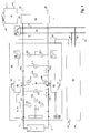
- a photovoltaic power generator element 10 which may comprise a solar module or a plurality of solar modules connected in series to form a string and/or a plurality of modules or strings connected in parallel is connected via a positive connecting line 11 and a negative connecting line 12 with a common bus bar 20 comprising a positive bus line 21 and a negative bus line 22.
- a mechanical switch 30 is arranged to selectively interrupt or provide a connection of the photovoltaic power generator via the connecting lines 11,12 to the common bus bar 20.
- the mechanical switch comprises two switches 31,32, the former being arranged to selectively interrupt the positive connecting line 21 and the latter being arranged to selectively interrupt the negative connecting line 22.
- the mechanical switch may be an electromagnetically actuated relay with one or two contacts or may alternatively be a bi-polar semiconductor switch.
- a first voltmeter 100 is arranged between the mechanical switch 30 and the photovoltaic power generator element 10.
- the first voltmeter 100 is adapted to measure the voltage across the positive and negative connecting lines. With the mechanical switch in the closed position the voltmeter 100 will measure the voltage across the positive and negative common bus line, i.e. the voltage produced in total by all photovoltaic power generator elements connected to the common bus bar 20. With the mechanical switch in the open position the first voltmeter 100 will measure the voltage provided by the photovoltaic power generator element 10.
- a second voltmeter 110 is arranged between the mechanical switch 30 and the common bus bar 20 to measure the voltage across the positive and negative connecting lines 11,12. With the mechanical switch in the closed position the second voltmeter 110 will measure the same nominal voltage as the first voltmeter 100 excluding the switch losses. The switch losses can be analysed for switch quality monitoring. With the mechanical switch 30 in the open position the second voltmeter 110 will measure the voltage in the common bus bar, i.e. the voltage produced by those solar modules connected to the common bus bar except the solar generator element 10.
- a third and fourth voltmeter 120,130 is arranged between the mechanical switch 30 and the solar generator element 10 to measure the voltage of the positive and negative connecting lines versus ground, respectively.
- a fifth and sixth voltmeter 140,150 is arranged adjacent to the second voltmeter 110 to measure the voltage of the positive and negative connecting lines versus ground, respectively, between the mechanical switch 30 and the common bus bar 20.
- a first and second current meter 200, 210 is arranged to measure the current in the positive and negative connecting lines, respectively, between the solar module 10 and the mechanical switch 30.
- a third and fourth current meter 220,230 is arranged to measure the current in the positive and negative connecting lines, respectively, between the mechanical switch 30 and the common bus bar 20.
- a seventh and eighth voltmeter 160, 170 are arranged adjacent to the voltmeters 110, 100, respectively.
- the voltmeters 160, 170 allow to precisily measure the voltage and to determine the measurement error induced by the resistance of the current meters.
- the data acquired by the voltmeters 100-160 and the current meters 200-230 are transferred via a dc-insulating device 40,41 to a controller 60,61.
- voltmeters 180, 190 are provided to directly measure the voltage drop across the switches 31, 32.
- the controller 60 comprises two control units 61, 63 to monitor the voltages and currents measured by the voltmeters 100-190 and the current meters 200-230.
- the control units 61, 63 directly control the actuation of the mechanical switches 31, 32 in order to open the switches in case of any irregularities shown by the measured values.
- a central power and data management control 90 is connected with the control 60, 61 to receive information about the voltages and currents measured by the voltmeters 100-190 and the current meters 200-230 and about the actuation and status of the mechanical switch 30.
- a direct switch 62 connected to the control unit 61 may be activated manually to open the switch 31.
- a direct switch 64 connected to the control unit 63 may be activated manually to open the switch 32.
- a direct switch 92 connected to the central power and management control 90 may be activated manually to open the switch 31, 32 and the switches of any other strings connected to the common bus bar 20.
- the direct switches 62, 64, 92 overrule any actuation command of the control units 61, 63 and the central power and management control 90.
- a theft detection unit 70 is connected to the positive and negative connecting line 11,12 between the solar generator 10 and the mechanical switch 30 to send a pulse signal through the solar element with the mechanical switch 30 in open or closed position.
- the analysis of this pulse signal is performed by the installed voltmeters and current meters and the controller 60 but it is alternatively possible to use the theft detection unit 70 itself for this purpose or to analyze the pulse signal in the central power and data management control 90.
- Element 71 prevents the string of floating and generation of high voltages induced by autocharging of the string itself.
- a temperature sensor 97 and an irradiation sensor 98 is provided for measuring the environmental temperature and the irradiation in the vicinity of the solar modules.
- the temperature and irradiation values measured by the respective sensors are transmitted to the controller 63.
- the common bus bar 20 is connected to a semiconductor switch 80 which is arranged to temporarily short-cut the positive and negative common bus lines 21,22.
- the semiconductor switch 80 is controlled by the power and data management control 90.
- the power and data management control 90 is connected via a wide area data bus 91 with the controller 60, 61, 63 and any other controller of additional strings 50 connected to the common bus bar 20.
- An additional string, represented schematically by reference number 50 is coupled via connecting lines 51,52 to the common bus bar 20.
- the string 50 is connected in parallel to the string formed by the solar generator element 10.
- a common over-voltage and lightning protection unit 95 is provided, which is arranged to selectively separate the output connecting lines 23,24 connecting the common bus bar 20 with an inverter (not shown).
- a temperature sensing element integrated in the over-voltage and lightning protection unit 95 reports via a data line 96 to the central power and data management control 90 for monitoring the quality and rest of lifetime of the surge protection element. With this information replacement can be made before failure of this element.
- Fig. 1 The preferred embodiment shown in Fig. 1 works as follows:
- the power and data management unit 90 actuates the semiconductor switch 80 to shortcut the common bus bar 20.
- the current which may induce an arc when opening the switch 30 is reduced to the current produced by the solar generator element 10.
- the semiconductor switch 80 is opened again.
- the measured voltage and current values are transferred to the controller and to the central power and data management unit 90 to analyze the reason for failure and to take the necessary steps to overcome the problem.
- the controller or the power and data management control actuates the mechanical switch 30 to close the switches 31, 32 so that the solar generator element 10 is connected with the common bus bar 20 again.
- the semiconductor switch 80 is closed shortly before closing the mechanical switch 30 and opened immediately after the mechanical switch 30 has reached its closed position.
- the controller 50 sends a signal to the pole control units 60,61 to open the mechanical switch 30 to improve safety conditions and to reduce power consumption of the switch driver.
- the theft detection unit 70 sends a pulse signal in time intervals of e.g. one minute to the connecting lines 11,12. A high impedance measurement of the resistance of the solar generator element 10 is performed via the resistor 71 and a sudden change of this resistance will signalize the removal of the solar generator element 10.
- the temperature sensing element (98) reports to the controller 96 for lifetime monitoring of the surge protection.
- An irradiation 97 and temperature 98 sensing element transfers the actual environmental values in the data bus 91 or wide area data bus 91.
- a dedicated voltage meter 180 or 190 across each switch is used for switch quality monitoring.
- Fig. 2 shows a solar module 300 comprising three solar elements 310, 320, 330.
- the solar elements 310-330 are connected in series.
- Fig. 3 shows two solar modules 400,410.
- Each of the modules 400, 410 comprises two solar elements 401, 402 and 411, 412 respectively.
- the solar modules 400,410 are connected in series to form a string.
- Fig. 4 shows two strings according to Fig. 3 which are connected in parallel.
- Fig. 5 shows three strings 610,620,630 each comprising three solar modules.
- the solar modules of each string are connected in series.
- the strings are connected in parallel using a connecting housing 640 which is hermetically sealed against humidity.
- the connecting housing 640 provides the sum of the current of the three strings 610-630 to an inverter 650.
- Fig. 6 shows an arrangement of three connecting housings 700-720 according to Fig. 5 , each of them connecting three strings of solar modules.
- each of the connecting housings is supplied to a common bus bar 751 connected to an inverter 750. Additionally, each of the connecting housings is connected via a data line with a wide area data bus 761 to supply the data of each of the strings to a central power and data management unit 760.
- Fig. 7 shows an arrangement example of a total of 18 strings. Each three of these strings are connected via a connecting housing 800-825 and each three of these connecting housings form an arrangement according to Fig. 6 , so that two arrangements according to Fig. 6 are shown in Fig. 7 .
- the common bus bar 851, 852 of each of the two arrangements shown in Fig. 7 is connected to a connection box 870, 875 collecting the current of three connecting housings, i.e. a total of nine strings.
- the two connection boxes are connected to an upper bus bar providing the sum current of the two connection boxes to an inverter 850.
- a wide area data bus 881 is provided which is connected with each of the connecting housings and supplies the data acquired for each of the strings to a central power and data management unit 880.
- FIG. 8 three or more circuits 960, 961,...962 corresponding to the controller 60 of Fig. 1 are shown.
- Each of the circuits include an optical coupling device 940 corresponding to the dc-insulating device 40, 41 of Fig. 1 .
- the circuits are power supplied by a common power supply 900.
- the circuits are connected to form a wired OR so that an alarm signal induced by a single circuit will provide this signal to all other circuits and thus set these circuits in alarm mode, too.
- Fig. 9 is schematic diagram showing a wiring scheme similar to Fig.8 .
- the output lines of an optical coupling device 1040 of each controller 1060 are connected to a comparator 1030.
- the output of the comparator 1060a is connected with a mechanical switch 1030 corresponding to the switches 31,32 of Fig. 1 .
- a common power supply 1000 supplies all controllers 1060. In case that the power supply breaks down, the mechanical switch is actuated to open. Alternatively, a logical actuation may be initiated via the optical coupling device 1040.
- a number of controllers 1260, 1261, 1262 are connected to a central power and data management control 1290 via a parallel wiring scheme.
- Each of the controllers 1260-1262 is connected to a mechanical switch 1230-1232, respectively.
- a number of controllers 1360, 1361, 1362 are connected to a central power and data management control 1390 via a loop-through wiring scheme.
- Each of the controllers 1360-1362 is connected to a mechanical switch 1330-1332, respectively.
- Fig. 12 shows a schematic diagram of another wiring scheme for a plurality of strings.
- Two controllers 1460, 1461 are connected to an intermediate power and data management control 1491 via a loop-through wiring scheme.
- two controllers 1462, 1463 are connected to an intermediate power and data management control 1492.
- the intermediate power and data management controls 1491, 1492 are connected in parallel to a central power and data management control 1490
- Fig. 13 is schematic diagram of a controller comprising a basic control unit 1560 and an advanced control unit 1590.
- the basic control unit comprises a number of comparators 1560a-c having adjustable limits.
- the advanced control unit comprises an analog-digital converter 1590a and a microcontroller 1590b having programmable limits. Both the basic and the advanced control unit are provided with the measured voltage and current values.
- the outputs of the basic and advanced control units are connected via two transistors in such a way so that both control units may independently effect an actuation of a mechanical switch 1530 via a relay 1520.
Landscapes
- Physics & Mathematics (AREA)
- General Physics & Mathematics (AREA)
- Photovoltaic Devices (AREA)
- Emergency Protection Circuit Devices (AREA)
Priority Applications (1)
| Application Number | Priority Date | Filing Date | Title |
|---|---|---|---|
| EP11168783.6A EP2369709B1 (de) | 2005-10-24 | 2005-10-24 | Lastschalter mit Sicherungen mit Steuerungsmanagement für Solarzellen |
Applications Claiming Priority (3)
| Application Number | Priority Date | Filing Date | Title |
|---|---|---|---|
| PCT/EP2005/011429 WO2007048421A2 (en) | 2005-10-24 | 2005-10-24 | Switch-fuse with control management for solar cells |
| EP11168783.6A EP2369709B1 (de) | 2005-10-24 | 2005-10-24 | Lastschalter mit Sicherungen mit Steuerungsmanagement für Solarzellen |
| EP05799316A EP1946418A2 (de) | 2005-10-24 | 2005-10-24 | Schalter-sicherung mit steuerverwaltung für solarzellen |
Related Parent Applications (2)
| Application Number | Title | Priority Date | Filing Date |
|---|---|---|---|
| EP05799316A Division EP1946418A2 (de) | 2005-10-24 | 2005-10-24 | Schalter-sicherung mit steuerverwaltung für solarzellen |
| EP05799316.4 Division | 2005-10-24 |
Publications (3)
| Publication Number | Publication Date |
|---|---|
| EP2369709A2 true EP2369709A2 (de) | 2011-09-28 |
| EP2369709A3 EP2369709A3 (de) | 2014-09-03 |
| EP2369709B1 EP2369709B1 (de) | 2016-05-04 |
Family
ID=36606420
Family Applications (2)
| Application Number | Title | Priority Date | Filing Date |
|---|---|---|---|
| EP05799316A Withdrawn EP1946418A2 (de) | 2005-10-24 | 2005-10-24 | Schalter-sicherung mit steuerverwaltung für solarzellen |
| EP11168783.6A Active EP2369709B1 (de) | 2005-10-24 | 2005-10-24 | Lastschalter mit Sicherungen mit Steuerungsmanagement für Solarzellen |
Family Applications Before (1)
| Application Number | Title | Priority Date | Filing Date |
|---|---|---|---|
| EP05799316A Withdrawn EP1946418A2 (de) | 2005-10-24 | 2005-10-24 | Schalter-sicherung mit steuerverwaltung für solarzellen |
Country Status (2)
| Country | Link |
|---|---|
| EP (2) | EP1946418A2 (de) |
| WO (1) | WO2007048421A2 (de) |
Cited By (2)
| Publication number | Priority date | Publication date | Assignee | Title |
|---|---|---|---|---|
| DE202011050696U1 (de) * | 2011-07-12 | 2012-10-22 | Sma Solar Technology Ag | Sicherungsvorrichtung für photovoltaische (PV-)Generatoren |
| US10720777B2 (en) | 2018-10-15 | 2020-07-21 | Inventus Holdings, Llc | DC integration of battery for expanding the DC:AC ratio limit of a PV inverter |
Families Citing this family (93)
| Publication number | Priority date | Publication date | Assignee | Title |
|---|---|---|---|---|
| US10693415B2 (en) | 2007-12-05 | 2020-06-23 | Solaredge Technologies Ltd. | Testing of a photovoltaic panel |
| US11881814B2 (en) | 2005-12-05 | 2024-01-23 | Solaredge Technologies Ltd. | Testing of a photovoltaic panel |
| US11569659B2 (en) | 2006-12-06 | 2023-01-31 | Solaredge Technologies Ltd. | Distributed power harvesting systems using DC power sources |
| US11735910B2 (en) | 2006-12-06 | 2023-08-22 | Solaredge Technologies Ltd. | Distributed power system using direct current power sources |
| US11687112B2 (en) | 2006-12-06 | 2023-06-27 | Solaredge Technologies Ltd. | Distributed power harvesting systems using DC power sources |
| US8013472B2 (en) | 2006-12-06 | 2011-09-06 | Solaredge, Ltd. | Method for distributed power harvesting using DC power sources |
| US11888387B2 (en) | 2006-12-06 | 2024-01-30 | Solaredge Technologies Ltd. | Safety mechanisms, wake up and shutdown methods in distributed power installations |
| WO2009073868A1 (en) | 2007-12-05 | 2009-06-11 | Solaredge, Ltd. | Safety mechanisms, wake up and shutdown methods in distributed power installations |
| US11855231B2 (en) | 2006-12-06 | 2023-12-26 | Solaredge Technologies Ltd. | Distributed power harvesting systems using DC power sources |
| US9088178B2 (en) | 2006-12-06 | 2015-07-21 | Solaredge Technologies Ltd | Distributed power harvesting systems using DC power sources |
| US8947194B2 (en) | 2009-05-26 | 2015-02-03 | Solaredge Technologies Ltd. | Theft detection and prevention in a power generation system |
| US8473250B2 (en) | 2006-12-06 | 2013-06-25 | Solaredge, Ltd. | Monitoring of distributed power harvesting systems using DC power sources |
| US11309832B2 (en) | 2006-12-06 | 2022-04-19 | Solaredge Technologies Ltd. | Distributed power harvesting systems using DC power sources |
| US8816535B2 (en) | 2007-10-10 | 2014-08-26 | Solaredge Technologies, Ltd. | System and method for protection during inverter shutdown in distributed power installations |
| US8319471B2 (en) | 2006-12-06 | 2012-11-27 | Solaredge, Ltd. | Battery power delivery module |
| US8319483B2 (en) | 2007-08-06 | 2012-11-27 | Solaredge Technologies Ltd. | Digital average input current control in power converter |
| US8963369B2 (en) | 2007-12-04 | 2015-02-24 | Solaredge Technologies Ltd. | Distributed power harvesting systems using DC power sources |
| US11728768B2 (en) | 2006-12-06 | 2023-08-15 | Solaredge Technologies Ltd. | Pairing of components in a direct current distributed power generation system |
| US8618692B2 (en) | 2007-12-04 | 2013-12-31 | Solaredge Technologies Ltd. | Distributed power system using direct current power sources |
| US9130401B2 (en) | 2006-12-06 | 2015-09-08 | Solaredge Technologies Ltd. | Distributed power harvesting systems using DC power sources |
| US8384243B2 (en) | 2007-12-04 | 2013-02-26 | Solaredge Technologies Ltd. | Distributed power harvesting systems using DC power sources |
| US9112379B2 (en) | 2006-12-06 | 2015-08-18 | Solaredge Technologies Ltd. | Pairing of components in a direct current distributed power generation system |
| US11296650B2 (en) | 2006-12-06 | 2022-04-05 | Solaredge Technologies Ltd. | System and method for protection during inverter shutdown in distributed power installations |
| AT505731B1 (de) * | 2007-08-29 | 2013-03-15 | Fronius Int Gmbh | Verfahren zur diebstahlerkennung bei einer photovoltaikanlage und wechselrichter für eine photovoltaikanlage |
| CA2737134C (en) * | 2007-10-15 | 2017-10-10 | Ampt, Llc | Systems for highly efficient solar power |
| US7884278B2 (en) * | 2007-11-02 | 2011-02-08 | Tigo Energy, Inc. | Apparatuses and methods to reduce safety risks associated with photovoltaic systems |
| US8933321B2 (en) | 2009-02-05 | 2015-01-13 | Tigo Energy, Inc. | Systems and methods for an enhanced watchdog in solar module installations |
| US8823218B2 (en) | 2007-11-02 | 2014-09-02 | Tigo Energy, Inc. | System and method for enhanced watch dog in solar panel installations |
| US11228278B2 (en) | 2007-11-02 | 2022-01-18 | Tigo Energy, Inc. | System and method for enhanced watch dog in solar panel installations |
| ITMO20070344A1 (it) | 2007-11-16 | 2009-05-17 | Meta System Spa | Impianto fotovoltaico perfezionato |
| WO2009072077A1 (en) | 2007-12-05 | 2009-06-11 | Meir Adest | Testing of a photovoltaic panel |
| WO2009072075A2 (en) | 2007-12-05 | 2009-06-11 | Solaredge Technologies Ltd. | Photovoltaic system power tracking method |
| US8049523B2 (en) | 2007-12-05 | 2011-11-01 | Solaredge Technologies Ltd. | Current sensing on a MOSFET |
| US8289742B2 (en) | 2007-12-05 | 2012-10-16 | Solaredge Ltd. | Parallel connected inverters |
| US11264947B2 (en) | 2007-12-05 | 2022-03-01 | Solaredge Technologies Ltd. | Testing of a photovoltaic panel |
| DE102008008505A1 (de) * | 2008-02-11 | 2009-08-13 | Siemens Aktiengesellschaft | PV-Teilgenerator-Anschlusskasten für eine PV-Anlage sowie PV-Anlage mit einer Vielzahl derartiger PV-Teilgenerator-Anschlusskästen |
| FR2927733B1 (fr) * | 2008-02-19 | 2011-05-06 | Photowatt Internat | Installation de modules photovoltaiques telecommandes |
| WO2009118682A2 (en) | 2008-03-24 | 2009-10-01 | Solaredge Technolgies Ltd. | Zero current switching |
| US9000617B2 (en) | 2008-05-05 | 2015-04-07 | Solaredge Technologies, Ltd. | Direct current power combiner |
| ES2345750R (es) | 2008-05-12 | 2010-10-13 | Ingeteam Energy, S.A. | Circuito electrico de proteccion de sistemas fotovoltaicos. |
| EP2133926A1 (de) * | 2008-06-11 | 2009-12-16 | SAVIO S.p.A. | Diebstahlschutzvorrichtung für photovoltaische Kollektoren |
| DE102008039205A1 (de) * | 2008-08-22 | 2010-04-22 | EPROTECH Reimann e.K. Jürgen Reimann | Vorrichtung und Verfahren zur Überwachung einzelner Photovoltaikmodule einer Photovoltaikanlage |
| IT1391748B1 (it) * | 2008-08-29 | 2012-01-27 | Bames Srl | Dispositivo di controllo e segnalamento per moduli fotovoltaici |
| ITTO20080676A1 (it) * | 2008-09-16 | 2010-03-17 | Saet Impianti Speciali S R L | Dispositivo antifurto per stringhe di pannelli fotovoltaici ed impiantofotovoltaico comprendente detto dispositivo antifurto |
| US8273979B2 (en) | 2008-10-15 | 2012-09-25 | Xandex, Inc. | Time averaged modulated diode apparatus for photovoltaic application |
| DE102009006999A1 (de) * | 2009-01-30 | 2010-08-12 | Schott Solar Ag | Alarmsystem für Photovoltaikmodule sowie Verfahren zum Schutz einer Photovoltaikanlage vor Diebstahl |
| EP2602831B1 (de) | 2009-05-22 | 2014-07-16 | Solaredge Technologies Ltd. | Elektrisch isolierter hitzeabschwächender Verbindungskasten |
| DE102009022570A1 (de) * | 2009-05-25 | 2010-12-02 | Yamaichi Electronics Deutschland Gmbh | Anschlußdose, Solarpaneel und Verfahren |
| DE102009054039B4 (de) * | 2009-05-25 | 2016-03-31 | Yamaichi Electronics Deutschland Gmbh | Anschlussdose für ein Solarmodul, Verwendung und Verfahren |
| ATE555531T1 (de) | 2009-08-06 | 2012-05-15 | Sma Solar Technology Ag | Rückstromsensor für parallel geschaltete solarmodule |
| EP2282388A1 (de) | 2009-08-06 | 2011-02-09 | SMA Solar Technology AG | Vorrichtung zur Einspeisung elektrischer Energie von einer Vielzahl von Strings von Photovoltaikmodulen in ein Stromnetz |
| IT1397326B1 (it) * | 2009-10-28 | 2013-01-10 | Shd Di Bassignana Luigi & C Snc | Solar control systemsistema di controllo diagnostico ed antifurto per pannelli solari. |
| ITVI20090266A1 (it) * | 2009-10-30 | 2011-04-30 | Pria Fabio Dalla | Dispositivo di sicurezza, particolarmente per impianti fotovoltaici, ed impianto fotovoltaico realizzato con detto dispositivo |
| US8710699B2 (en) | 2009-12-01 | 2014-04-29 | Solaredge Technologies Ltd. | Dual use photovoltaic system |
| US8271599B2 (en) | 2010-01-08 | 2012-09-18 | Tigo Energy, Inc. | Systems and methods for an identification protocol between a local controller and a master controller in a photovoltaic power generation system |
| FR2955210B1 (fr) * | 2010-01-12 | 2012-08-03 | Thierry Arnaud | Systeme de gestion et de commande de panneaux photovoltaiques |
| US8766696B2 (en) | 2010-01-27 | 2014-07-01 | Solaredge Technologies Ltd. | Fast voltage level shifter circuit |
| US9007210B2 (en) * | 2010-04-22 | 2015-04-14 | Tigo Energy, Inc. | Enhanced system and method for theft prevention in a solar power array during nonoperative periods |
| EP3567562B1 (de) * | 2010-05-31 | 2023-06-28 | Solaredge Technologies Ltd. | Diebstahldetektion und -verhinderung in einem stromerzeugungssystem |
| DE102010036816A1 (de) * | 2010-08-03 | 2012-02-09 | Newtos Ag | Verfahren und Vorrichtung zur Überwachung und Steuerung einer Photovoltaik-Anlage |
| US8482893B2 (en) | 2010-09-28 | 2013-07-09 | Xantrex Technology Inc. | Integrated photovoltaic source circuit combiner and protection subsystem |
| AT510512B1 (de) * | 2010-09-30 | 2015-08-15 | Fronius Int Gmbh | Wechselrichter |
| US10230310B2 (en) | 2016-04-05 | 2019-03-12 | Solaredge Technologies Ltd | Safety switch for photovoltaic systems |
| GB2485527B (en) | 2010-11-09 | 2012-12-19 | Solaredge Technologies Ltd | Arc detection and prevention in a power generation system |
| US10673222B2 (en) | 2010-11-09 | 2020-06-02 | Solaredge Technologies Ltd. | Arc detection and prevention in a power generation system |
| US10673229B2 (en) | 2010-11-09 | 2020-06-02 | Solaredge Technologies Ltd. | Arc detection and prevention in a power generation system |
| ITVR20100227A1 (it) * | 2010-11-29 | 2012-05-30 | Metech Italia S R L | Dispositivo di sicurezza per impianti fotovoltaici |
| DE102011056107A1 (de) * | 2010-12-07 | 2012-06-14 | Hst Elektronik Gmbh | Sicherheitseinrichtung für Photovoltaikanlagen |
| GB2486408A (en) | 2010-12-09 | 2012-06-20 | Solaredge Technologies Ltd | Disconnection of a string carrying direct current |
| GB2483317B (en) | 2011-01-12 | 2012-08-22 | Solaredge Technologies Ltd | Serially connected inverters |
| US8570005B2 (en) | 2011-09-12 | 2013-10-29 | Solaredge Technologies Ltd. | Direct current link circuit |
| GB2498365A (en) | 2012-01-11 | 2013-07-17 | Solaredge Technologies Ltd | Photovoltaic module |
| GB2498791A (en) | 2012-01-30 | 2013-07-31 | Solaredge Technologies Ltd | Photovoltaic panel circuitry |
| GB2498790A (en) | 2012-01-30 | 2013-07-31 | Solaredge Technologies Ltd | Maximising power in a photovoltaic distributed power system |
| US9853565B2 (en) | 2012-01-30 | 2017-12-26 | Solaredge Technologies Ltd. | Maximized power in a photovoltaic distributed power system |
| GB2499991A (en) | 2012-03-05 | 2013-09-11 | Solaredge Technologies Ltd | DC link circuit for photovoltaic array |
| CN104488159B (zh) | 2012-05-25 | 2018-03-23 | 太阳能安吉科技有限公司 | 用于互联的直流电源的电路 |
| US10115841B2 (en) | 2012-06-04 | 2018-10-30 | Solaredge Technologies Ltd. | Integrated photovoltaic panel circuitry |
| DE102012105807B3 (de) * | 2012-07-02 | 2013-11-07 | Sma Solar Technology Ag | Verfahren und Vorrichtung zur Bestimmung und Signalisierung einer Modultechnologie eines Photovoltaikgenerators |
| US9548619B2 (en) | 2013-03-14 | 2017-01-17 | Solaredge Technologies Ltd. | Method and apparatus for storing and depleting energy |
| US9941813B2 (en) | 2013-03-14 | 2018-04-10 | Solaredge Technologies Ltd. | High frequency multi-level inverter |
| US9397497B2 (en) | 2013-03-15 | 2016-07-19 | Ampt, Llc | High efficiency interleaved solar power supply system |
| EP3506370B1 (de) | 2013-03-15 | 2023-12-20 | Solaredge Technologies Ltd. | Bypass-mechanismus |
| US9318974B2 (en) | 2014-03-26 | 2016-04-19 | Solaredge Technologies Ltd. | Multi-level inverter with flying capacitor topology |
| DE102014115601B3 (de) * | 2014-10-27 | 2016-01-07 | Sma Solar Technology Ag | Combinerbox mit motorischer Überstromsicherung |
| CN105827179B (zh) * | 2015-01-04 | 2018-09-07 | 华为技术有限公司 | 一种光伏系统 |
| JP6529294B2 (ja) * | 2015-03-17 | 2019-06-12 | 日東工業株式会社 | パワーコンディショナの雷保護システム |
| CN117130027A (zh) | 2016-03-03 | 2023-11-28 | 太阳能安吉科技有限公司 | 用于映射发电设施的方法 |
| US11081608B2 (en) | 2016-03-03 | 2021-08-03 | Solaredge Technologies Ltd. | Apparatus and method for determining an order of power devices in power generation systems |
| US10599113B2 (en) | 2016-03-03 | 2020-03-24 | Solaredge Technologies Ltd. | Apparatus and method for determining an order of power devices in power generation systems |
| US11177663B2 (en) | 2016-04-05 | 2021-11-16 | Solaredge Technologies Ltd. | Chain of power devices |
| US11018623B2 (en) | 2016-04-05 | 2021-05-25 | Solaredge Technologies Ltd. | Safety switch for photovoltaic systems |
| CN113508506B (zh) * | 2020-12-31 | 2022-09-16 | 华为数字能源技术有限公司 | 一种光伏发电系统、光伏逆变器及直流汇流箱 |
Citations (5)
| Publication number | Priority date | Publication date | Assignee | Title |
|---|---|---|---|---|
| EP1014403A1 (de) | 1998-12-21 | 2000-06-28 | Asea Brown Boveri AG | Strombegrenzender Schalter |
| DE10002870A1 (de) | 2000-01-24 | 2001-08-23 | Abb Research Ltd | Vorrichtung zum Begrenzen eines Stromes |
| JP2002367046A (ja) | 2001-06-11 | 2002-12-20 | Nec Eng Ltd | 太陽電池モジュールの盗難防止装置 |
| WO2004090993A2 (fr) | 2003-04-02 | 2004-10-21 | Electricite De France | Panneau photovoltaique securise contre le vol |
| EP1538645A1 (de) | 2003-12-05 | 2005-06-08 | Société Technique pour l'Energie Atomique TECHNICATOME | Hybrid-Leistungsschalter |
Family Cites Families (9)
| Publication number | Priority date | Publication date | Assignee | Title |
|---|---|---|---|---|
| JPH01177823A (ja) * | 1987-12-29 | 1989-07-14 | Shikoku Electric Power Co Inc | 太陽電池回路の保護方法 |
| JPH07177652A (ja) * | 1993-12-17 | 1995-07-14 | Canon Inc | 太陽光発電システムおよび太陽光発電システムの保護方式 |
| JP3329168B2 (ja) * | 1995-01-13 | 2002-09-30 | オムロン株式会社 | 逆流防止装置 |
| JPH09182279A (ja) * | 1995-10-26 | 1997-07-11 | Nitto Kogyo Kk | 太陽光発電システムにおける短絡検出装置 |
| DE19844977A1 (de) * | 1998-09-30 | 2000-04-13 | Siemens Solar Gmbh | Schutzsystem für ein Solarmodul |
| JP3500566B2 (ja) * | 1998-11-26 | 2004-02-23 | 富士通アクセス株式会社 | 太陽電池の盗難検知回路及び太陽電池配電盤 |
| JP3731197B2 (ja) * | 1999-03-31 | 2006-01-05 | 株式会社中電工 | 太陽光発電における出力測定方法及び装置 |
| JP2001068706A (ja) * | 1999-08-25 | 2001-03-16 | Sanyo Electric Co Ltd | 太陽電池装置 |
| US6593520B2 (en) * | 2000-02-29 | 2003-07-15 | Canon Kabushiki Kaisha | Solar power generation apparatus and control method therefor |
-
2005
- 2005-10-24 WO PCT/EP2005/011429 patent/WO2007048421A2/en active Application Filing
- 2005-10-24 EP EP05799316A patent/EP1946418A2/de not_active Withdrawn
- 2005-10-24 EP EP11168783.6A patent/EP2369709B1/de active Active
Patent Citations (5)
| Publication number | Priority date | Publication date | Assignee | Title |
|---|---|---|---|---|
| EP1014403A1 (de) | 1998-12-21 | 2000-06-28 | Asea Brown Boveri AG | Strombegrenzender Schalter |
| DE10002870A1 (de) | 2000-01-24 | 2001-08-23 | Abb Research Ltd | Vorrichtung zum Begrenzen eines Stromes |
| JP2002367046A (ja) | 2001-06-11 | 2002-12-20 | Nec Eng Ltd | 太陽電池モジュールの盗難防止装置 |
| WO2004090993A2 (fr) | 2003-04-02 | 2004-10-21 | Electricite De France | Panneau photovoltaique securise contre le vol |
| EP1538645A1 (de) | 2003-12-05 | 2005-06-08 | Société Technique pour l'Energie Atomique TECHNICATOME | Hybrid-Leistungsschalter |
Cited By (2)
| Publication number | Priority date | Publication date | Assignee | Title |
|---|---|---|---|---|
| DE202011050696U1 (de) * | 2011-07-12 | 2012-10-22 | Sma Solar Technology Ag | Sicherungsvorrichtung für photovoltaische (PV-)Generatoren |
| US10720777B2 (en) | 2018-10-15 | 2020-07-21 | Inventus Holdings, Llc | DC integration of battery for expanding the DC:AC ratio limit of a PV inverter |
Also Published As
| Publication number | Publication date |
|---|---|
| WO2007048421A2 (en) | 2007-05-03 |
| WO2007048421A3 (en) | 2007-07-12 |
| EP2369709B1 (de) | 2016-05-04 |
| EP2369709A3 (de) | 2014-09-03 |
| EP1946418A2 (de) | 2008-07-23 |
Similar Documents
| Publication | Publication Date | Title |
|---|---|---|
| EP2369709B1 (de) | Lastschalter mit Sicherungen mit Steuerungsmanagement für Solarzellen | |
| US8749934B2 (en) | Reverse current sensor | |
| CN106663937A (zh) | 选择性断路器 | |
| CN102474097A (zh) | 用于向电网供应来自多个光伏模块串列的电能的设备 | |
| CN201278339Y (zh) | 一种限载智能断路器 | |
| EP2393178A2 (de) | Schutz-, Überwachungs- und Anzeigevorrichtung für eine Direktstromerzeugungsvorrichtung oder einer Vielzahl von Reihungen | |
| CN104348143A (zh) | 一种检验电弧故障/瞬态检测器的正确运行的方法和系统 | |
| CN104934927A (zh) | 一种光伏直流侧短路保护装置及其控制方法 | |
| JP5889143B2 (ja) | 太陽光発電システムおよびアーク検出保護装置 | |
| JP2007209151A (ja) | 配電系統のループ運用システム及び方法 | |
| KR101684679B1 (ko) | 접속반내의 단자볼트 텐션상태 검출을 통한 화재방지기능을 가지는 태양광발전시스템 | |
| KR20180024673A (ko) | 태양광발전 채널별 감시장치 | |
| CN101944727A (zh) | 带检测装置的浪涌保护器 | |
| CN108181501A (zh) | 一种具有保护作用的电流信号采集电路 | |
| KR100330745B1 (ko) | 디지털 재폐로 계전기 | |
| CN100452599C (zh) | 检测电源模块输出端短路的保护方法 | |
| CN202541351U (zh) | 直流牵引供电杂散电流控制系统 | |
| US20050146815A1 (en) | Electrical, transmission/substation/distribution shunt capacitor switching and control system with integrated, automatically resettable, overcurrent protection | |
| CN204391726U (zh) | 一种新型电涌保护器 | |
| CN105262066A (zh) | 一种直流智能保护单元 | |
| CN113054624A (zh) | 一种智能型低压电涌保护器专用断路器及其控制方法 | |
| CN204391727U (zh) | 一种新型电涌保护器 | |
| CN217385636U (zh) | 一种智能监测低压配电仪表 | |
| CN217087164U (zh) | 开关箱和ups配电系统 | |
| CN213813868U (zh) | 断路器控制回路故障点定位装置 |
Legal Events
| Date | Code | Title | Description |
|---|---|---|---|
| PUAI | Public reference made under article 153(3) epc to a published international application that has entered the european phase |
Free format text: ORIGINAL CODE: 0009012 |
|
| AC | Divisional application: reference to earlier application |
Ref document number: 1946418 Country of ref document: EP Kind code of ref document: P |
|
| AK | Designated contracting states |
Kind code of ref document: A2 Designated state(s): AT BE BG CH CY CZ DE DK EE ES FI FR GB GR HU IE IS IT LI LT LU LV MC NL PL PT RO SE SI SK TR |
|
| AX | Request for extension of the european patent |
Extension state: AL BA HR MK YU |
|
| RAP1 | Party data changed (applicant data changed or rights of an application transferred) |
Owner name: ROBERT BOSCH GMBH |
|
| PUAL | Search report despatched |
Free format text: ORIGINAL CODE: 0009013 |
|
| AK | Designated contracting states |
Kind code of ref document: A3 Designated state(s): AT BE BG CH CY CZ DE DK EE ES FI FR GB GR HU IE IS IT LI LT LU LV MC NL PL PT RO SE SI SK TR |
|
| AX | Request for extension of the european patent |
Extension state: AL BA HR MK YU |
|
| RIC1 | Information provided on ipc code assigned before grant |
Ipc: H02H 5/10 20060101AFI20140730BHEP Ipc: H01L 31/042 20140101ALI20140730BHEP Ipc: G08B 13/14 20060101ALI20140730BHEP Ipc: H01L 31/02 20060101ALI20140730BHEP |
|
| 17P | Request for examination filed |
Effective date: 20150303 |
|
| RBV | Designated contracting states (corrected) |
Designated state(s): AT BE BG CH CY CZ DE DK EE ES FI FR GB GR HU IE IS IT LI LT LU LV MC NL PL PT RO SE SI SK TR |
|
| GRAP | Despatch of communication of intention to grant a patent |
Free format text: ORIGINAL CODE: EPIDOSNIGR1 |
|
| INTG | Intention to grant announced |
Effective date: 20151112 |
|
| GRAS | Grant fee paid |
Free format text: ORIGINAL CODE: EPIDOSNIGR3 |
|
| GRAA | (expected) grant |
Free format text: ORIGINAL CODE: 0009210 |
|
| AC | Divisional application: reference to earlier application |
Ref document number: 1946418 Country of ref document: EP Kind code of ref document: P |
|
| AK | Designated contracting states |
Kind code of ref document: B1 Designated state(s): AT BE BG CH CY CZ DE DK EE ES FI FR GB GR HU IE IS IT LI LT LU LV MC NL PL PT RO SE SI SK TR |
|
| REG | Reference to a national code |
Ref country code: GB Ref legal event code: FG4D |
|
| REG | Reference to a national code |
Ref country code: CH Ref legal event code: EP |
|
| REG | Reference to a national code |
Ref country code: AT Ref legal event code: REF Ref document number: 797656 Country of ref document: AT Kind code of ref document: T Effective date: 20160515 |
|
| REG | Reference to a national code |
Ref country code: IE Ref legal event code: FG4D |
|
| REG | Reference to a national code |
Ref country code: DE Ref legal event code: R096 Ref document number: 602005049270 Country of ref document: DE |
|
| REG | Reference to a national code |
Ref country code: NL Ref legal event code: MP Effective date: 20160504 |
|
| REG | Reference to a national code |
Ref country code: LT Ref legal event code: MG4D |
|
| REG | Reference to a national code |
Ref country code: FR Ref legal event code: PLFP Year of fee payment: 12 |
|
| PG25 | Lapsed in a contracting state [announced via postgrant information from national office to epo] |
Ref country code: FI Free format text: LAPSE BECAUSE OF FAILURE TO SUBMIT A TRANSLATION OF THE DESCRIPTION OR TO PAY THE FEE WITHIN THE PRESCRIBED TIME-LIMIT Effective date: 20160504 Ref country code: NL Free format text: LAPSE BECAUSE OF FAILURE TO SUBMIT A TRANSLATION OF THE DESCRIPTION OR TO PAY THE FEE WITHIN THE PRESCRIBED TIME-LIMIT Effective date: 20160504 Ref country code: LT Free format text: LAPSE BECAUSE OF FAILURE TO SUBMIT A TRANSLATION OF THE DESCRIPTION OR TO PAY THE FEE WITHIN THE PRESCRIBED TIME-LIMIT Effective date: 20160504 |
|
| REG | Reference to a national code |
Ref country code: AT Ref legal event code: MK05 Ref document number: 797656 Country of ref document: AT Kind code of ref document: T Effective date: 20160504 |
|
| PG25 | Lapsed in a contracting state [announced via postgrant information from national office to epo] |
Ref country code: SE Free format text: LAPSE BECAUSE OF FAILURE TO SUBMIT A TRANSLATION OF THE DESCRIPTION OR TO PAY THE FEE WITHIN THE PRESCRIBED TIME-LIMIT Effective date: 20160504 Ref country code: PT Free format text: LAPSE BECAUSE OF FAILURE TO SUBMIT A TRANSLATION OF THE DESCRIPTION OR TO PAY THE FEE WITHIN THE PRESCRIBED TIME-LIMIT Effective date: 20160905 Ref country code: ES Free format text: LAPSE BECAUSE OF FAILURE TO SUBMIT A TRANSLATION OF THE DESCRIPTION OR TO PAY THE FEE WITHIN THE PRESCRIBED TIME-LIMIT Effective date: 20160504 Ref country code: LV Free format text: LAPSE BECAUSE OF FAILURE TO SUBMIT A TRANSLATION OF THE DESCRIPTION OR TO PAY THE FEE WITHIN THE PRESCRIBED TIME-LIMIT Effective date: 20160504 Ref country code: GR Free format text: LAPSE BECAUSE OF FAILURE TO SUBMIT A TRANSLATION OF THE DESCRIPTION OR TO PAY THE FEE WITHIN THE PRESCRIBED TIME-LIMIT Effective date: 20160805 |
|
| PG25 | Lapsed in a contracting state [announced via postgrant information from national office to epo] |
Ref country code: IT Free format text: LAPSE BECAUSE OF FAILURE TO SUBMIT A TRANSLATION OF THE DESCRIPTION OR TO PAY THE FEE WITHIN THE PRESCRIBED TIME-LIMIT Effective date: 20160504 |
|
| PG25 | Lapsed in a contracting state [announced via postgrant information from national office to epo] |
Ref country code: DK Free format text: LAPSE BECAUSE OF FAILURE TO SUBMIT A TRANSLATION OF THE DESCRIPTION OR TO PAY THE FEE WITHIN THE PRESCRIBED TIME-LIMIT Effective date: 20160504 Ref country code: SK Free format text: LAPSE BECAUSE OF FAILURE TO SUBMIT A TRANSLATION OF THE DESCRIPTION OR TO PAY THE FEE WITHIN THE PRESCRIBED TIME-LIMIT Effective date: 20160504 Ref country code: EE Free format text: LAPSE BECAUSE OF FAILURE TO SUBMIT A TRANSLATION OF THE DESCRIPTION OR TO PAY THE FEE WITHIN THE PRESCRIBED TIME-LIMIT Effective date: 20160504 Ref country code: CZ Free format text: LAPSE BECAUSE OF FAILURE TO SUBMIT A TRANSLATION OF THE DESCRIPTION OR TO PAY THE FEE WITHIN THE PRESCRIBED TIME-LIMIT Effective date: 20160504 Ref country code: RO Free format text: LAPSE BECAUSE OF FAILURE TO SUBMIT A TRANSLATION OF THE DESCRIPTION OR TO PAY THE FEE WITHIN THE PRESCRIBED TIME-LIMIT Effective date: 20160504 |
|
| REG | Reference to a national code |
Ref country code: DE Ref legal event code: R097 Ref document number: 602005049270 Country of ref document: DE |
|
| REG | Reference to a national code |
Ref country code: DE Ref legal event code: R081 Ref document number: 602005049270 Country of ref document: DE Owner name: SMA SOLAR TECHNOLOGY AG, DE Free format text: FORMER OWNER: ROBERT BOSCH GMBH, 70469 STUTTGART, DE |
|
| PG25 | Lapsed in a contracting state [announced via postgrant information from national office to epo] |
Ref country code: BE Free format text: LAPSE BECAUSE OF FAILURE TO SUBMIT A TRANSLATION OF THE DESCRIPTION OR TO PAY THE FEE WITHIN THE PRESCRIBED TIME-LIMIT Effective date: 20160504 Ref country code: PL Free format text: LAPSE BECAUSE OF FAILURE TO SUBMIT A TRANSLATION OF THE DESCRIPTION OR TO PAY THE FEE WITHIN THE PRESCRIBED TIME-LIMIT Effective date: 20160504 Ref country code: AT Free format text: LAPSE BECAUSE OF FAILURE TO SUBMIT A TRANSLATION OF THE DESCRIPTION OR TO PAY THE FEE WITHIN THE PRESCRIBED TIME-LIMIT Effective date: 20160504 |
|
| PLBE | No opposition filed within time limit |
Free format text: ORIGINAL CODE: 0009261 |
|
| STAA | Information on the status of an ep patent application or granted ep patent |
Free format text: STATUS: NO OPPOSITION FILED WITHIN TIME LIMIT |
|
| RAP2 | Party data changed (patent owner data changed or rights of a patent transferred) |
Owner name: SMA SOLAR TECHNOLOGY AG |
|
| 26N | No opposition filed |
Effective date: 20170207 |
|
| PG25 | Lapsed in a contracting state [announced via postgrant information from national office to epo] |
Ref country code: SI Free format text: LAPSE BECAUSE OF FAILURE TO SUBMIT A TRANSLATION OF THE DESCRIPTION OR TO PAY THE FEE WITHIN THE PRESCRIBED TIME-LIMIT Effective date: 20160504 |
|
| REG | Reference to a national code |
Ref country code: CH Ref legal event code: PL |
|
| PG25 | Lapsed in a contracting state [announced via postgrant information from national office to epo] |
Ref country code: MC Free format text: LAPSE BECAUSE OF FAILURE TO SUBMIT A TRANSLATION OF THE DESCRIPTION OR TO PAY THE FEE WITHIN THE PRESCRIBED TIME-LIMIT Effective date: 20160504 |
|
| REG | Reference to a national code |
Ref country code: IE Ref legal event code: MM4A |
|
| PG25 | Lapsed in a contracting state [announced via postgrant information from national office to epo] |
Ref country code: LI Free format text: LAPSE BECAUSE OF NON-PAYMENT OF DUE FEES Effective date: 20161031 Ref country code: CH Free format text: LAPSE BECAUSE OF NON-PAYMENT OF DUE FEES Effective date: 20161031 |
|
| REG | Reference to a national code |
Ref country code: GB Ref legal event code: 732E Free format text: REGISTERED BETWEEN 20170727 AND 20170802 |
|
| PG25 | Lapsed in a contracting state [announced via postgrant information from national office to epo] |
Ref country code: LU Free format text: LAPSE BECAUSE OF NON-PAYMENT OF DUE FEES Effective date: 20161024 |
|
| REG | Reference to a national code |
Ref country code: FR Ref legal event code: PLFP Year of fee payment: 13 |
|
| PG25 | Lapsed in a contracting state [announced via postgrant information from national office to epo] |
Ref country code: IE Free format text: LAPSE BECAUSE OF NON-PAYMENT OF DUE FEES Effective date: 20161024 |
|
| REG | Reference to a national code |
Ref country code: FR Ref legal event code: TP Owner name: SMA SOLAR TECHNOLOGY AG, DE Effective date: 20180111 |
|
| PG25 | Lapsed in a contracting state [announced via postgrant information from national office to epo] |
Ref country code: CY Free format text: LAPSE BECAUSE OF FAILURE TO SUBMIT A TRANSLATION OF THE DESCRIPTION OR TO PAY THE FEE WITHIN THE PRESCRIBED TIME-LIMIT Effective date: 20160504 Ref country code: HU Free format text: LAPSE BECAUSE OF FAILURE TO SUBMIT A TRANSLATION OF THE DESCRIPTION OR TO PAY THE FEE WITHIN THE PRESCRIBED TIME-LIMIT; INVALID AB INITIO Effective date: 20051024 |
|
| PG25 | Lapsed in a contracting state [announced via postgrant information from national office to epo] |
Ref country code: IS Free format text: LAPSE BECAUSE OF FAILURE TO SUBMIT A TRANSLATION OF THE DESCRIPTION OR TO PAY THE FEE WITHIN THE PRESCRIBED TIME-LIMIT Effective date: 20160504 Ref country code: TR Free format text: LAPSE BECAUSE OF FAILURE TO SUBMIT A TRANSLATION OF THE DESCRIPTION OR TO PAY THE FEE WITHIN THE PRESCRIBED TIME-LIMIT Effective date: 20160504 |
|
| PG25 | Lapsed in a contracting state [announced via postgrant information from national office to epo] |
Ref country code: BG Free format text: LAPSE BECAUSE OF FAILURE TO SUBMIT A TRANSLATION OF THE DESCRIPTION OR TO PAY THE FEE WITHIN THE PRESCRIBED TIME-LIMIT Effective date: 20160504 |
|
| REG | Reference to a national code |
Ref country code: FR Ref legal event code: PLFP Year of fee payment: 14 |
|
| PGFP | Annual fee paid to national office [announced via postgrant information from national office to epo] |
Ref country code: FR Payment date: 20221020 Year of fee payment: 18 |
|
| PGFP | Annual fee paid to national office [announced via postgrant information from national office to epo] |
Ref country code: GB Payment date: 20221024 Year of fee payment: 18 Ref country code: DE Payment date: 20221020 Year of fee payment: 18 |