EP2369183A1 - Ventilator - Google Patents
Ventilator Download PDFInfo
- Publication number
- EP2369183A1 EP2369183A1 EP20110156467 EP11156467A EP2369183A1 EP 2369183 A1 EP2369183 A1 EP 2369183A1 EP 20110156467 EP20110156467 EP 20110156467 EP 11156467 A EP11156467 A EP 11156467A EP 2369183 A1 EP2369183 A1 EP 2369183A1
- Authority
- EP
- European Patent Office
- Prior art keywords
- fan
- stator
- rotor
- wheel
- radial
- Prior art date
- Legal status (The legal status is an assumption and is not a legal conclusion. Google has not performed a legal analysis and makes no representation as to the accuracy of the status listed.)
- Granted
Links
Images



Classifications
-
- F—MECHANICAL ENGINEERING; LIGHTING; HEATING; WEAPONS; BLASTING
- F04—POSITIVE - DISPLACEMENT MACHINES FOR LIQUIDS; PUMPS FOR LIQUIDS OR ELASTIC FLUIDS
- F04D—NON-POSITIVE-DISPLACEMENT PUMPS
- F04D25/00—Pumping installations or systems
- F04D25/02—Units comprising pumps and their driving means
- F04D25/08—Units comprising pumps and their driving means the working fluid being air, e.g. for ventilation
- F04D25/082—Units comprising pumps and their driving means the working fluid being air, e.g. for ventilation the unit having provision for cooling the motor
-
- F—MECHANICAL ENGINEERING; LIGHTING; HEATING; WEAPONS; BLASTING
- F04—POSITIVE - DISPLACEMENT MACHINES FOR LIQUIDS; PUMPS FOR LIQUIDS OR ELASTIC FLUIDS
- F04D—NON-POSITIVE-DISPLACEMENT PUMPS
- F04D25/00—Pumping installations or systems
- F04D25/02—Units comprising pumps and their driving means
- F04D25/06—Units comprising pumps and their driving means the pump being electrically driven
- F04D25/0606—Units comprising pumps and their driving means the pump being electrically driven the electric motor being specially adapted for integration in the pump
- F04D25/0613—Units comprising pumps and their driving means the pump being electrically driven the electric motor being specially adapted for integration in the pump the electric motor being of the inside-out type, i.e. the rotor is arranged radially outside a central stator
- F04D25/0646—Details of the stator
-
- F—MECHANICAL ENGINEERING; LIGHTING; HEATING; WEAPONS; BLASTING
- F04—POSITIVE - DISPLACEMENT MACHINES FOR LIQUIDS; PUMPS FOR LIQUIDS OR ELASTIC FLUIDS
- F04D—NON-POSITIVE-DISPLACEMENT PUMPS
- F04D29/00—Details, component parts, or accessories
- F04D29/58—Cooling; Heating; Diminishing heat transfer
- F04D29/5806—Cooling the drive system
-
- F—MECHANICAL ENGINEERING; LIGHTING; HEATING; WEAPONS; BLASTING
- F04—POSITIVE - DISPLACEMENT MACHINES FOR LIQUIDS; PUMPS FOR LIQUIDS OR ELASTIC FLUIDS
- F04D—NON-POSITIVE-DISPLACEMENT PUMPS
- F04D29/00—Details, component parts, or accessories
- F04D29/58—Cooling; Heating; Diminishing heat transfer
- F04D29/582—Cooling; Heating; Diminishing heat transfer specially adapted for elastic fluid pumps
- F04D29/584—Cooling; Heating; Diminishing heat transfer specially adapted for elastic fluid pumps cooling or heating the machine
-
- H—ELECTRICITY
- H02—GENERATION; CONVERSION OR DISTRIBUTION OF ELECTRIC POWER
- H02K—DYNAMO-ELECTRIC MACHINES
- H02K1/00—Details of the magnetic circuit
- H02K1/06—Details of the magnetic circuit characterised by the shape, form or construction
- H02K1/22—Rotating parts of the magnetic circuit
- H02K1/32—Rotating parts of the magnetic circuit with channels or ducts for flow of cooling medium
-
- H—ELECTRICITY
- H02—GENERATION; CONVERSION OR DISTRIBUTION OF ELECTRIC POWER
- H02K—DYNAMO-ELECTRIC MACHINES
- H02K11/00—Structural association of dynamo-electric machines with electric components or with devices for shielding, monitoring or protection
- H02K11/30—Structural association with control circuits or drive circuits
- H02K11/33—Drive circuits, e.g. power electronics
-
- H—ELECTRICITY
- H02—GENERATION; CONVERSION OR DISTRIBUTION OF ELECTRIC POWER
- H02K—DYNAMO-ELECTRIC MACHINES
- H02K21/00—Synchronous motors having permanent magnets; Synchronous generators having permanent magnets
- H02K21/12—Synchronous motors having permanent magnets; Synchronous generators having permanent magnets with stationary armatures and rotating magnets
- H02K21/22—Synchronous motors having permanent magnets; Synchronous generators having permanent magnets with stationary armatures and rotating magnets with magnets rotating around the armatures, e.g. flywheel magnetos
-
- H—ELECTRICITY
- H02—GENERATION; CONVERSION OR DISTRIBUTION OF ELECTRIC POWER
- H02K—DYNAMO-ELECTRIC MACHINES
- H02K9/00—Arrangements for cooling or ventilating
- H02K9/02—Arrangements for cooling or ventilating by ambient air flowing through the machine
- H02K9/04—Arrangements for cooling or ventilating by ambient air flowing through the machine having means for generating a flow of cooling medium
-
- H—ELECTRICITY
- H02—GENERATION; CONVERSION OR DISTRIBUTION OF ELECTRIC POWER
- H02K—DYNAMO-ELECTRIC MACHINES
- H02K9/00—Arrangements for cooling or ventilating
- H02K9/02—Arrangements for cooling or ventilating by ambient air flowing through the machine
- H02K9/04—Arrangements for cooling or ventilating by ambient air flowing through the machine having means for generating a flow of cooling medium
- H02K9/06—Arrangements for cooling or ventilating by ambient air flowing through the machine having means for generating a flow of cooling medium with fans or impellers driven by the machine shaft
-
- H—ELECTRICITY
- H02—GENERATION; CONVERSION OR DISTRIBUTION OF ELECTRIC POWER
- H02K—DYNAMO-ELECTRIC MACHINES
- H02K2213/00—Specific aspects, not otherwise provided for and not covered by codes H02K2201/00 - H02K2211/00
- H02K2213/03—Machines characterised by numerical values, ranges, mathematical expressions or similar information
-
- H—ELECTRICITY
- H02—GENERATION; CONVERSION OR DISTRIBUTION OF ELECTRIC POWER
- H02K—DYNAMO-ELECTRIC MACHINES
- H02K7/00—Arrangements for handling mechanical energy structurally associated with dynamo-electric machines, e.g. structural association with mechanical driving motors or auxiliary dynamo-electric machines
- H02K7/14—Structural association with mechanical loads, e.g. with hand-held machine tools or fans
Definitions
- the present invention relates to a fan, consisting of an electric external rotor motor and a fan wheel, wherein the external rotor motor consists of a stator encapsulated with an insulating material and the stator cup-shaped surrounding, the fan wheel-bearing rotor (external rotor).
- Such a fan is from the document EP 1 404 008 A2 known, wherein an electric motor is described with an external rotor rotor, which carries on its outer periphery a fan.
- the stator has a stator insulation which consists in particular of a thermosetting plastic, a stator laminated core provided with stator windings being pressed together with the insulating material with simultaneous shaping. Since the rotor also encloses the stator, a rather high heating in the area of the stator can occur during operation.
- the present invention is based on the object to improve a fan of the type mentioned so that an effective engine cooling and favorable flow properties are guaranteed.
- the ventilation openings of the rotor and, on the other hand, the passage between the peripheral edge of the rotor and the stator support a cooling air flow through the motor, wherein the cooling air flows around the stator through an existing between this and the rotor circumferential gap.
- the direction of the flow depends on the design of the fan and in particular on which axial side during operation in each case a negative pressure or an overpressure is formed.
- a negative pressure in the case of a radial or diagonal fan in the region of an axial intake opening, a negative pressure, and when the rotor with the end wall and the ventilation openings facing the suction opening of the fan wheel, is sucked by the negative pressure cooling air from the opposite side, ie the cooling air flows through the passage at the peripheral edge of the rotor, flows around the stator and exits through the ventilation openings of the end wall again.
- the flow direction of the cooling air depends on the actual conveying direction of the fan wheel, and that it is always opposite to the conveying direction.
- the ventilation openings of the rotor and the rib projections of the stator are now designed and arranged relative to one another such that, during operation of the rotor, the motor cooling air swirls in the region between the stator rib extensions and the rotor ventilation openings by a kind of "quirring effect" becomes.
- the achieved engine cooling is therefore an interaction between the ventilation openings of the rotor and the ribs of the stator, which are preferably formed from the insulating material.
- both the ventilation openings with a certain number of openings and the rib projections with a certain number of ribs are in particular distributed radially symmetrically over the circumference.
- the number of openings and the number of fins should be unequal and preferably also least common. These uneven and preferably divisive numbers of the vents on the one hand and the rib approaches on the other hand lead to favorable, d. H. low operating noise, in particular by avoiding resonance or rotational sound phenomena.
- at least two, but preferably a larger number of ventilation openings are present.
- seven ventilation openings and six rib projections are provided. The size of the ventilation openings together defines an effective opening cross-section whose ratio to the total, axially projected cross-sectional area of the rotor lies in the range of 10% to 30%.
- the ventilation openings each have a circumferential, nozzle-like in the direction of the stator and with a maximum distance of 4 mm to the vicinity of the rib projections projecting opening edge.
- These projecting opening edges reinforce the "quirring effect" according to the invention by cooperating as “counter-approaches” with the rib projections; the cooling air is thus swirled on both axially opposite sides between relatively mutually rotating lugs.
- the rotor in the radially outer region of its front end wall passes over a chamfer-like wall section into a cylindrical circumferential wall, wherein the chamfer-like wall section coincides with the longitudinal axis of the Motor includes a chamfer angle in the range of 30 ° to 60 °, preferably 50 °.
- the ventilation wall having the end wall of the rotor slightly tapered in a cone angle to the longitudinal axis, wherein the cone angle in the range of 60 ° to 80 °, preferably 70 °, is located.
- FIG. 1 and 2 Each results in an inventive fan 1 consists of an electric external rotor motor 2 and a fan wheel 4.
- the in the other FIGS. 3 to 8 separately illustrated external rotor motor 2 in turn consists of a stator 6 (see in particular Fig. 5a ) and a stator 6 cup-shaped rotor (outer rotor) 8 (FIG. Fig. 5b ).
- the stator 6, including a stator windings 10 provided with stator laminated core 12 is encapsulated under molding with an insulating material 14. This can be done by pressing, but in particular overmolding with a suitable plastic, for.
- thermoset done, whereby the stator 6 according to Fig. 5a receives a total cylindrical basic shape.
- the fan 4 is mounted on the outer circumference of the rotor 8, so that the rotor 8 carries the fan 4.
- the electric external rotor motor 2 is designed as an electronically commutated, permanent magnet excited DC motor, wherein the rotor 8 has permanent magnets 16 on its inner circumference. This will be done in particular on the cuts in Fig. 6 and 8th directed.
- the stator 6 generates a magnetic rotating field in a manner known per se, whereby the rotor 8 rotates by interaction with the permanent magnets 16.
- the windings 10 of the stator 6 are controlled by control electronics (commutated).
- the rotor 8 has ventilation openings 20 in a front end wall 18.
- the stator 6 on a front end surface 22 distributed over the circumference arranged on the ventilation openings 20 of the rotor 8 axially opposite rib projections 24 on.
- Fig. 5a such as Fig. 8 directed.
- the rib projections 24 are preferably integrally formed from the insulating material 14. During operation of the fan 1, the rotor 8 thus rotates with the ventilation openings 20 relative to the stator 6 with the rib projections 24 Fig.
- Fig. 8 results, the cooling air in the area between the rotor end wall 18 and the stator end face 22 by interaction between the ventilation openings 20 and the fin projections 24 is intensively swirled, whereby the cooling air effectively absorbs heat from the stator 6.
- the cooling air flows z. B. according to the indicated arrow direction 28 by a circumferential gap 32 between the stator 6 and the rotor 8, wherein it flows radially inwardly through a gap region 34 between a peripheral edge 36 of the rotor 8 and a stator 38 and flows out of the ventilation openings 20 again.
- This flow of cooling air is in Fig. 8 illustrated by arrows. It should be noted, however, that depending on the fan design, a reverse flow direction of the cooling air is possible.
- the ventilation openings 20 have a trapezoidal or circular sector-shaped opening shape with rounded corner areas, whereby they are wider in the manner of pie pieces from the inside radially outward.
- a good utilization of the available area is achieved, d. H.
- the total available surface in the area of the end face 22 (substantially the axially projected cross-sectional area of the rotor 8) can be interrupted by the ventilation openings 20 to a large extent of 10% to 30%.
- each ventilation opening 20 has a circumferential, nozzle-like in the direction of the stator 6 extending opening edge 40. These opening edges 40 extend to a maximum axial distance of up to 4 mm near the rib projections 24. Thus, in operation, the vent openings 20 rotate with their opening edges 40 close relative to the rib projections 24, thereby achieving effective air swirling.
- the rib projections 24 of the stator 6 are according to FIG Fig. 5a preferably arranged radially, star-shaped on the end face 22.
- the end face 22 lies in a plane perpendicular to the motor longitudinal axis (axis of rotation of the rotor 8).
- a concentric, axially projecting annular web shoulder 42 is formed in the radially inner region.
- the rib projections 24 initially extend with reduced height and then with axially increasing height radially outward. The surfaces thus increase radially from the inside to the outside.
- the basic shape of the rib projections 24 in axial plan view is narrowed approximately rectangular or slightly trapezoidal outward.
- the rib projections 24 have in the circumferential direction on flank surfaces which may be formed obliquely so that the rib projections 24 narrow in the axial direction.
- the shape of the rib projections 24 in interaction with the ventilation openings 20 and their opening edges 40 has an influence on the turbulence of the cooling air entering through the ventilation openings 20 during operation.
- the rib projections 24 increase the effective convection surface of the stator 6.
- the ventilation openings 20 having end wall 18 of the rotor 8 is slightly tapered in a cone angle ⁇ to the longitudinal axis 50 inclined.
- the cone angle ⁇ is preferably in the range of 60 ° to 80 ° and in particular of 70 °.
- the chamfer-like, the end wall 18 and the peripheral wall 48 connecting wall portion 46 includes with the longitudinal axis 50 preferably a chamfer angle ⁇ in the range of 30 ° to 60 ° and in particular 50 °.
- stator support 38 is formed as a flange-like, integrally molded portion of the insulating material 14 encapsulating the stator 6.
- the flange-like stator carrier 38 forms on the side remote from the stator 6 together with an additional housing part 54 (see the separate illustration in FIG Fig. 5c ) An electronics housing for unspecified control electronics.
- the housing part 54 also acts as a support member for the entire external rotor motor 2, by it via mounting parts 56 (see. Fig. 1 and 2 ) is attached or attachable to or in a fan housing.
- FIG. 1 For example, an embodiment is shown as a unilaterally aspirating radial fan, wherein the fan wheel 4 is formed as a radial wheel having a front axial inlet (adjacent to the inlet portion 52), a plurality of radial blades, and a radial exhaust direction. The radial blades are arranged in a conventional manner between cover plates.
- the fan housing may optionally have a front guard 58 in the inlet region 52.
- Fig. 2 an embodiment is shown as a double-sided sucking radial fan, wherein the fan wheel 4 is formed as a radial wheel with two axially opposite inlets, a plurality of radial blades and also a radial discharge direction.
- the radial blades may be curved backward, forward curved or optionally also straight (radial).
- the rotor 8 may be formed as a molded part made of metal or plastic.
- the peripheral wall 48 also acts as a magnetic yoke element for the permanent magnets arranged inside 16. If, alternatively, the rotor 8 mainly consists of plastic, a return ring is additionally required on the inside.
- the invention is not limited to the illustrated and described embodiments, but also includes all the same in the context of the invention embodiments. It is expressly emphasized that the exemplary embodiments are not limited to all the features in combination, but rather each individual partial feature may also have an inventive meaning independently of all other partial features. Furthermore, the invention is not yet available the feature combination defined in claim 1 is limited, but may also be defined by any other combination of certain features of all individually disclosed individual features. This means that in principle virtually every individual feature of claim 1 can be omitted or replaced by at least one individual feature disclosed elsewhere in the application. In this respect, the claim 1 is to be understood only as a first formulation attempt for an invention.
Landscapes
- Engineering & Computer Science (AREA)
- Power Engineering (AREA)
- Mechanical Engineering (AREA)
- General Engineering & Computer Science (AREA)
- Physics & Mathematics (AREA)
- Thermal Sciences (AREA)
- Microelectronics & Electronic Packaging (AREA)
- Motor Or Generator Cooling System (AREA)
- Structures Of Non-Positive Displacement Pumps (AREA)
- Connection Of Motors, Electrical Generators, Mechanical Devices, And The Like (AREA)
- Brushless Motors (AREA)
Abstract
Description
- Die vorliegende Erfindung betrifft einen Ventilator, bestehend aus einem Elektro-Außenläufermotor und einem Ventilatorrad, wobei der Außenläufermotor aus einem mit einem Isoliermaterial umkapselten Stator und einem den Stator topfförmig umschließenden, das Ventilatorrad tragenden Rotor (Außenläufer) besteht.
- Ein derartiger Ventilator ist aus dem Dokument
EP 1 404 008 A2 bekannt, worin ein Elektromotor mit einem Außenläufer-Rotor beschrieben ist, der auf seinem Außenumfang ein Lüfterrad trägt. Der Stator weist eine insbesondere aus einem Duroplast bestehende Statorisolierung auf, wobei ein mit Statorwicklungen versehenes Statorblechpaket unter gleichzeitiger Formgebung mit dem Isoliermaterial umpresst ist. Indem der Rotor den Stator ebenfalls umschließt, kann im Betrieb eine recht hohe Erwärmung im Bereich des Stators auftreten. - Der vorliegenden Erfindung liegt die Aufgabe zu Grunde, einen Ventilator der genannten Art so zu verbessern, dass eine effektive Motor-Entwärmung sowie günstige strömungstechnische Eigenschaften gewährleistet sind.
- Erfindungsgemäß wird dies durch die Merkmale des Anspruchs 1 erreicht. Vorteilhafte Ausgestaltungsmerkmale und besondere Ausführungsarten der Erfindung sind in den abhängigen Ansprüchen enthalten.
- Erfindungsgemäß ist demnach vorgesehen, dass einerseits der Rotor in einer vorderen Stirnwandung Lüftungsöffnungen für eine Kühlluft-Strömung und andererseits der Stator auf einer vorderen Stirnfläche über den Umfang verteilt angeordnete, den Lüftungsöffnungen axial gegenüberliegende Rippenansätze aufweisen, wobei ein Spaltbereich zwischen einem der Stirnwandung gegenüberliegenden Umfangsrand des Rotors und einem flanschartigen Statorträger einen Durchlass für die im Betrieb den Stator umströmende Kühlluft-Strömung bildet. Somit ermöglichen einerseits die Lüftungsöffnungen des Rotors und andererseits der Durchlass zwischen dem Umfangsrand des Rotors und dem Statorträger eine Kühlluft-Durchströmung des Motors, wobei die Kühlluft den Stator durch einen zwischen diesem und dem Rotor vorhandenen Umfangsspalt hindurch umströmt. Hierbei hängt die Richtung der Durchströmung von der Bauart des Ventilators sowie insbesondere davon ab, auf welcher Axialseite im Betrieb sich jeweils ein Unterdruck bzw. ein Überdruck ausbildet. Beispielsweise entsteht im Falle eines Radial- oder Diagonalventilators im Bereich einer axialen Ansaugöffnung ein Unterdruck, und wenn der Rotor mit der Stirnwandung und den Lüftungsöffnungen der Ansaugöffnung des Ventilatorrades zugewandt ist, wird durch den Unterdruck Kühlluft von der gegenüberliegenden Seite her angesaugt, d. h. die Kühlluft strömt durch den Durchlass am Umfangsrand des Rotors ein, umströmt den Stator und tritt durch die Lüftungsöffnungen der Stirnwandung wieder aus. Im Falle eines Axialventilators hängt die Strömungsrichtung der Kühlluft von der eigentlichen Förderrichtung des Ventilatorrades ab, und zwar ist sie stets gegenläufig zur Förderrichtung.
- Dabei sind nun die Lüftungsöffnungen des Rotors und die Rippenansätze des Stators derart ausgebildet und relativ zueinander derart angeordnet, dass im Betrieb bei Rotation des Rotors die Motor-Kühlluft im Bereich zwischen den Stator-Rippenansätzen und den Rotor-Lüftungsöffnungen durch eine Art "Quirleffekt" verwirbelt wird. Von besonderer Bedeutung für die erreichte Motor-Entwärmung (Kühlung) ist demnach eine Wechselwirkung zwischen den Lüftungsöffnungen des Rotors und den bevorzugt aus dem Isoliermaterial angeformten Rippenansätzen des Stators. So wird die aufgrund des im Betrieb auf einer Seite des Ventilators herrschenden Unterdrucks angesaugte und dadurch als Kühlluft in den Motor einströmende Luft im Bereich zwischen den Lüftungsöffnungen und den Rippenansätzen - praktisch nach dem Prinzip eines Quirls - verwirbelt, was in Verbindung mit der durch die Rippenansätze vergrößerten, als Konvektionsfläche wirkenden Stator-Oberfläche eine sehr effektive Wärmeaufnahme (Konvektion) bewirkt, d. h. die Kühlluft nimmt die Motorwärme auf und entwärmt (kühlt) somit den Motor bzw. Stator. Die Kühlluft umströmt zudem den Stator durch den zwischen Rotor und Stator vorhandenen Umfangsspalt und entwärmt dabei den Stator weitergehend.
- Trotz der erfindungsgemäßen Kühlluft-Durchströmung ist der Ventilator auch für Anwendungen in Feuchtbereichen geeignet (beispielsweise für Kälte- und Klima-Anwendungen), weil der umkapselte, d. h. umpresste oder umspritzte Stator eine hohe IP-Schutzart gemäß DIN EN 60529 und DIN 40050 Teil 9 gewährleistet.
- In weiterer vorteilhafter Ausgestaltung sind sowohl die Lüftungsöffnungen mit einer bestimmten Öffnungs-Anzahl als auch die Rippenansätze mit einer bestimmten Rippen-Anzahl insbesondere radialsymmetrisch über den Umfang verteilt angeordnet. Dabei sollten die Öffnungs-Anzahl und die Rippen-Anzahl jedenfalls ungleich und bevorzugt auch teilerfremd sein. Diese ungleichen und bevorzugt auch teilerfremden Anzahlen der Lüftungsöffnungen einerseits und der Rippenansätze andererseits führen zu günstigen, d. h. geringen Betriebsgeräuschen insbesondere durch Vermeidung von Resonanz- bzw. Drehklangerscheinungen. Konkret sind mindestens zwei, bevorzugt aber eine größere Anzahl von Lüftungsöffnungen vorhanden. In einer vorteilhaften Ausführungsform sind beispielsweise sieben Lüftungsöffnungen und sechs Rippenansätze vorgesehen. Dabei definieren die Lüftungsöffnungen durch ihre Größe gemeinsam einen wirksamen Öffnungsquerschnitt, dessen Verhältnis zur gesamten, axial projizierten Querschnittsfläche des Rotors im Bereich von 10 % bis 30 % liegt.
- Es ist weiterhin vorteilhaft, wenn die Lüftungsöffnungen jeweils einen umlaufenden, düsenartig in Richtung des Stators und mit einem maximalen Abstand von 4 mm bis in die Nähe der Rippenansätze vorspringenden Öffnungsrand aufweisen. Diese vorspringenden Öffnungsränder verstärken den erfindungsgemäßen "Quirleffekt" noch, indem sie als "Gegenansätze" mit den Rippenansätzen zusammenwirken; die Kühlluft wird folglich auf beiden axial gegenüberliegenden Seiten zwischen relativ gegeneinander rotierenden Ansätzen verwirbelt.
- Gemäß einem weiteren Erfindungsaspekt ist zur Verbesserung der strömungstechnischen Eigenschaften, und zwar insbesondere für eine Ausgestaltung als Radialventilator, vorgesehen, dass der Rotor im radial äußeren Bereich seiner vorderen Stirnwandung über einen fasenartigen Wandungsabschnitt in eine zylindrische Umfangswandung übergeht, wobei der fasenartige Wandungsabschnitt mit der Längsachse des Motors einen Fasenwinkel im Bereich von 30° bis 60°,bevorzugt 50°, einschließt. Weiterhin ist es vorteilhaft, wenn die die Lüftungsöffnungen aufweisende Stirnwandung des Rotors leicht konisch in einem Konuswinkel zur Längsachse geneigt verläuft, wobei der Konuswinkel im Bereich von 60° bis 80°, vorzugsweise 70°, liegt. Durch diese besonderen Maßnahmen wird erreicht, dass im Falle eines Radialventilators auch bei kurzer axialer Baugröße, d. h. bei kompakter Bauform, im Bereich zwischen einem axialen Lufteinlass des Radialventilators, dem als Radialrad ausgebildeten Ventilatorrad und dem Rotor ein vergrößerter Einlassquerschnitt gebildet wird. Dies wird nachfolgend noch anhand der Zeichnungen genauer erläutert werden.
- Zudem werden auch weitere besondere Ausgestaltungsmerkmale und erreichte Vorteile im Folgenden noch erläutert werden. Dazu wird die Erfindung beispielhaft anhand der Zeichnungen und darin dargestellter bevorzugter Ausführungsformen genauer beschrieben. Es zeigen:
- Fig. 1
- einen erfindungsgemäßen Ventilator in einer ersten Ausführungsform als einseitig saugender Radialventilator (Radialgebläse) in einer teilgeschnittenen Seitenansicht,
- Fig. 2
- eine Ansicht analog zu
Fig. 1 einer zweiten Ausführungsform des Ventilators als doppelseitig saugender Radialventilator, - Fig. 3
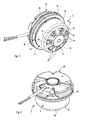
- eine gesonderte Perspektivansicht eines erfindungsgemäßen Außenläufermotors auf dessen Vorderseite (Läuferseite),
- Fig. 4
- eine Perspektivansicht des Außenläufermotors auf dessen Rückseite (Stator- bzw. Trägerseite),
- Fig. 5
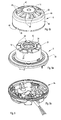
- eine perspektivische Explosionsdarstellung der wesentlichen Bestandteile des Außenläufermotors gemäß
Fig. 3 und 4 , und zwar - Fig. 5a
- den Stator,
- Fig. 5b
- den Rotor und
- Fig. 5c
- ein zusätzliches Montage- bzw. Gehäuseteil,
- Fig. 6
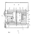
- einen vergrößerten Axialschnitt durch den Außenläufermotor nach
Fig. 3 bis 5 , - Fig. 7a
- einen Axialschnitt des Rotors (ohne innere Magnete),
- Fig. 7b
- den geschnittenen Rotor gemäß
Fig. 7a in einer Perspektivansicht und - Fig. 8
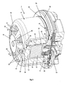
- eine vergrößerte und exzentrisch längsgeschnittene Perspektivansicht des erfindungsgemäßen Außenläufermotors zur Erläuterung der Kühlluft-Durchströmung.
- In den verschiedenen Figuren der Zeichnung sind gleiche Teile stets mit den gleichen Bezugszeichen versehen.
- Wie sich zunächst aus
Fig. 1 und2 jeweils ergibt, besteht ein erfindungsgemäßer Ventilator 1 aus einem Elektro-Außenläufermotor 2 und einem Ventilatorrad 4. Der in den weiterenFiguren 3 bis 8 gesondert veranschaulichte Außenläufermotor 2 besteht seinerseits aus einem Stator 6 (siehe insbesondereFig. 5a ) und einem den Stator 6 topfförmig von einer Axial-Seite her umschließenden Rotor (Außenläufer) 8 (Fig. 5b ). Wie sich besonders ausFig. 5a ,6 und8 ergibt, ist der Stator 6 unter Einschluss eines mit Statorwicklungen 10 versehenen Statorblechpaketes 12 unter Formgebung mit einem Isoliermaterial 14 umkapselt. Dies kann durch Umpressen, insbesondere aber Umspritzen mit einem geeigneten Kunststoff, z. B. Duroplast, erfolgen, wodurch der Stator 6 gemäßFig. 5a eine insgesamt zylindrische Grundform erhält. - Wie sich weiter aus
Fig. 1 und2 ergibt, ist das Ventilatorrad 4 auf dem Außenumfang des Rotors 8 befestigt, so dass der Rotor 8 das Ventilatorrad 4 trägt. - Bevorzugt ist der Elektro-Außenläufermotor 2 als elektronisch kommutierter, permanentmagneterregter Gleichstrommotor ausgebildet, wobei der Rotor 8 auf seinem inneren Umfang Permanentmagnete 16 aufweist. Hierzu wird insbesondere auf die Schnitte in
Fig. 6 und8 verwiesen. Der Stator 6 erzeugt in an sich bekannter Weise ein magnetisches Drehfeld, wodurch sich durch Wechselwirkung mit den Permanentmagneten 16 der Rotor 8 dreht. Zur Erzeugung des Drehfeldes werden die Wicklungen 10 des Stators 6 von einer Steuerelektronik angesteuert (kommutiert). - Erfindungsgemäß ist nun einerseits vorgesehen, dass der Rotor 8 in einer vorderen Stirnwandung 18 Lüftungsöffnungen 20 aufweist. Andererseits weist der Stator 6 auf einer vorderen Stirnfläche 22 über den Umfang verteilt angeordnete, den Lüftungsöffnungen 20 des Rotors 8 axial gegenüberliegende Rippenansätze 24 auf. Dazu wird insbesondere auf
Fig. 5a sowieFig. 8 verwiesen. Bevorzugt sind die Rippenansätze 24 aus dem Isoliermaterial 14 einstückig angeformt. Im Betrieb des Ventilators 1 rotiert somit der Rotor 8 mit den Lüftungsöffnungen 20 relativ zu dem Stator 6 mit den Rippenansätzen 24. Dabei wird gemäßFig. 1 und2 von dem Ventilatorrad 4 Luft in Richtung von eingezeichneten Pfeilen 26 angesaugt, wobei die angesaugte Luft bestimmungsgemäß durch das Ventilatorrad 4 beschleunigt und in Pfeilrichtung 30 ausgeblasen wird. Bedingt durch einen sich dabei ausbildenden Unterdruck- im dargestellten Beispiel als Radialventilator im Bereich vor der Stirnwandung 18 - entsteht zudem eine Kühlluft-Durchströmung, die durch Pfeile 28 angedeutet ist. - Wie sich insbesondere aus
Fig. 8 ergibt, wird die Kühlluft im Bereich zwischen der Rotor-Stirnwandung 18 und der Stator-Stirnfläche 22 durch Wechselwirkung zwischen den Lüftungsöffnungen 20 und den Rippenansätzen 24 intensiv verwirbelt, wodurch die Kühlluft effektiv Wärme aus dem Stator 6 aufnimmt. Die Kühlluft strömt z. B. entsprechend der eingezeichneten Pfeilrichtung 28 durch einen Umfangsspalt 32 zwischen Stator 6 und Rotor 8, wobei sie über einen Spaltbereich 34 zwischen einem Umfangsrand 36 des Rotors 8 und einem Statorträger 38 radial von außen einströmt und aus den Lüftungsöffnungen 20 wieder ausströmt. Diese Strömung der Kühlluft ist inFig. 8 durch Pfeile veranschaulicht. Dazu ist allerdings zu bemerken, dass je nach Ventilator-Ausführung auch eine umgekehrte Strömungsrichtung der Kühlluft möglich ist. - Zweckmäßig sind die Lüftungsöffnungen 20 mit einer bestimmten Öffnungs-Anzahl x radialsymmetrisch über den Umfang verteilt angeordnet, wobei mindestens zwei Lüftungsöffnungen 20 vorgesehen sind (x ≥ 2). Entsprechend sind auch die Rippenansätze 24 mit einer bestimmten Rippen-Anzahl y bevorzugt radialsymmetrisch über den Umfang verteilt angeordnet. Dabei ist es vorteilhaft, wenn die Anzahlen x, y der Lüftungsöffnungen 20 und der Rippenansätze 24 jedenfalls ungleich und insbesondere auch mathematisch teilerfremd sind. Somit gilt x ≠ y und vorzugsweise x ⊥ y. Durch diese Ausgestaltung wird ein günstiges Geräuschverhalten erreicht. Bei dem dargestellten, bevorzugten Ausführungsbeispiel sind sieben Lüftungsöffnungen 20 (x = 7) und sechs Rippenansätze 24 (y = 6) vorgesehen. Die Erfindung ist hierauf aber nicht beschränkt.
- Es ist weiterhin vorteilhaft, wenn die Lüftungsöffnungen 20 eine trapezförmige bzw. kreisringsektorförmige Öffnungsform mit verrundeten Eckbereichen aufweisen, wodurch sie nach Art von Tortenstücken von innen radial nach außen breiter werden. Hierdurch wird eine gute Ausnutzung der zur Verfügung stehenden Fläche erreicht, d. h. die insgesamt zur Verfügung stehende Oberfläche im Bereich der Stirnfläche 22 (im Wesentlichen die axial projizierte Querschnittsfläche des Rotors 8) kann zu einem großen Anteil von 10 % bis 30 % durch die Lüftungsöffnungen 20 unterbrochen werden.
- In weiterer vorteilhafter Ausgestaltung weist jede Lüftungsöffnung 20 einen umlaufenden, sich düsenartig in Richtung des Stators 6 erstreckenden Öffnungsrand 40 auf. Diese Öffnungsränder 40 erstrecken sich mit einem maximalen axialen Abstand von bis zu 4 mm bis in die Nähe der Rippenansätze 24. Im Betrieb rotieren somit die Lüftungsöffnungen 20 mit ihren Öffnungsrändern 40 nahe relativ zu den Rippenansätzen 24, wodurch eine effektive Luftverwirbelung erreicht wird.
- Was nun die Rippenansätze 24 des Stators 6 betrifft, so sind diese gemäß
Fig. 5a vorzugsweise radial, sternförmig auf der Stirnfläche 22 angeordnet. Die Stirnfläche 22 liegt in einer zur Motorlängsachse (Rotationsachse des Rotors 8) senkrechten Ebene. Im radial inneren Bereich ist ein konzentrischer, axial vorspringender Ringstegansatz 42 gebildet. Ausgehend von diesem Ringstegansatz 42 erstrecken sich die Rippenansätze 24 zunächst mit reduzierter Höhe und dann mit axial ansteigender Höhe radial nach außen. Die Oberflächen steigen somit radial von innen nach außen an. Die Grundform der Rippenansätze 24 in axialer Draufsicht ist etwa rechteckig oder leicht trapezförmig nach außen verschmälert. Die Rippenansätze 24 weisen in Umfangsrichtung Flankenflächen auf, die derart schräg ausgebildet sein können, dass sich die Rippenansätze 24 in axialer Richtung verschmälern. Die Form der Rippenansätze 24 hat in Wechselwirkung mit den Lüftungsöffnungen 20 und ihren Öffnungsrändern 40 einen Einfluss auf die Verwirbelung der im Betrieb durch die Lüftungsöffnungen 20 eintretenden Kühlluft. Zudem vergrößern die Rippenansätze 24 die wirksame Konvektionsfläche des Stators 6. - Wie sich noch aus
Fig. 3 ,5b ,7a,b und8 ergibt, kann im Bereich des Umfangsrandes 36 des Rotors 8 mindestens eine den Strömungsquerschnitt für die Kühlluft vergrößernde Ausnehmung 44 gebildet sein. - Ein weiterer Erfindungskomplex beschäftigt sich mit einer verbesserten strömungstechnischen Ausgestaltung des Ventilators 1. In diesem Zusammenhang ist vorgesehen, dass der Rotor 8 im radial äußeren Bereich seiner vorderen Stirnwandung 18 über mindestens einen fasenartigen Wandungsabschnitt 46 in eine zylindrische Umfangswandung 48 übergeht. Gemäß
Fig. 7a verläuft zudem die die Lüftungsöffnungen 20 aufweisende Stirnwandung 18 des Rotors 8 leicht konisch in einem Konuswinkel α zur Längsachse 50 geneigt. Der Konuswinkel α liegt vorzugsweise im Bereich von 60° bis 80°und insbesondere von 70°. Der fasenartige, die Stirnwandung 18 und die Umfangswandung 48 verbindende Wandungsabschnitt 46 schließt mit der Längsachse 50 bevorzugt einen Fasenwinkel β im Bereich von 30° bis 60°und insbesondere 50° ein. - Durch diese beschriebene vorteilhafte Ausgestaltung wird im Vergleich zu einem Rotor, bei dem die Stirnwandung in einer zur Längsachse 50 senkrechten Ebene liegt und direkt rechtwinklig in die Umfangswandung 48 übergeht, praktisch eine Art Abrundung im äußeren vorderen Übergangsbereich zwischen der Stirnwandung 18 und der Umfangswandung 48 erreicht. Wie in
Fig. 1 veranschaulicht ist, wird dadurch eine Vergrößerung des Einlassquerschnitts erreicht, indem ein großer lichter Abstand A zwischen dem Rotor 8 und einem Einlassbereich 52 des Ventilators 1 in der Ausgestaltung als Radialventilator gebildet ist. Zusätzlich sind inFig. 1 gestrichelt die Verhältnisse mit einem herkömmlichen Ventilator veranschaulicht, wobei ein geringerer Abstand A' vorhanden ist. - In weiterer vorteilhafter Ausgestaltung ist gemäß
Fig. 5a vorgesehen, dass der Statorträger 38 als ein flanschartiger, einstückig angeformter Abschnitt des den Stator 6 umkapselnden Isoliermaterials 14 gebildet ist. Zudem bildet der flanschartige Statorträger 38 auf der von dem Stator 6 abgewandten Seite gemeinsam mit einem zusätzlichen Gehäuseteil 54 (siehe die gesonderte Darstellung inFig. 5c ) ein Elektronikgehäuse für eine nicht näher bezeichnete Steuerelektronik. Zudem fungiert das Gehäuseteil 54 auch als Trägerteil für den gesamten Außenläufermotor 2, indem es über Montageteile 56 (vgl.Fig. 1 und2 ) an oder in einem Ventilatorgehäuse befestigt oder befestigbar ist. - Abschließend sei nochmals erwähnt, dass die Erfindung sowohl für Radial- oder Diagonalventilatoren als auch grundsätzlich für Axialventilatoren geeignet ist. In
Fig. 1 ist beispielhaft eine Ausführung als einseitig saugender Radialventilator dargestellt, wobei das Ventilatorrad 4 als Radialrad mit einem vorderen axialen Einlass (im Anschluss an den Einlassbereich 52), mehreren Radialschaufeln und einer radialen Ausblasrichtung ausgebildet ist. Die Radialschaufeln sind in üblicher Weise zwischen Deckscheiben angeordnet. Das Ventilatorgehäuse kann gegebenenfalls ein vorderes Schutzgitter 58 im Einlassbereich 52 aufweisen. - In
Fig. 2 ist eine Ausführung als doppelseitig saugender Radialventilator dargestellt, wobei das Ventilatorrad 4 als Radialrad mit zwei axial gegenüberliegenden Einlässen, mehreren Radialschaufeln und ebenfalls einer radialen Ausblasrichtung ausgebildet ist. - In beiden Fällen gemäß
Fig. 1 und2 können die Radialschaufeln rückwärts gekrümmt, vorwärts gekrümmt oder gegebenenfalls auch gerade (radial) ausgeführt sein. - Der Rotor 8 kann als Formteil aus Metall oder aus Kunststoff gebildet sein. Bei einer Ausführung aus einem weichmagnetischen Metall wirkt die Umfangswandung 48 auch als magnetisches Rückschlusselement für die innenseitig angeordneten Permanentmagnete 16. Wenn alternativ dazu der Rotor 8 in der Hauptsache aus Kunststoff besteht, ist innenseitig zusätzlich ein Rückschlussring erforderlich.
- Die Erfindung ist nicht auf die dargestellten und beschriebenen Ausführungsbeispiele beschränkt, sondern umfasst auch alle im Sinne der Erfindung gleichwirkenden Ausführungen. Es wird ausdrücklich betont, dass die Ausführungsbeispiele nicht auf alle Merkmale in Kombination beschränkt sind, vielmehr kann jedes einzelne Teilmerkmal auch losgelöst von allen anderen Teilmerkmalen für sich eine erfinderische Bedeutung haben. Ferner ist die Erfindung bislang auch noch nicht auf die im Anspruch 1 definierte Merkmalskombination beschränkt, sondern kann auch durch jede beliebige andere Kombination von bestimmten Merkmalen aller insgesamt offenbarten Einzelmerkmalen definiert sein. Dies bedeutet, dass grundsätzlich praktisch jedes Einzelmerkmal des Anspruchs 1 weggelassen bzw. durch mindestens ein an anderer Stelle der Anmeldung offenbartes Einzelmerkmal ersetzt werden kann. Insofern ist der Anspruch 1 lediglich als ein erster Formulierungsversuch für eine Erfindung zu verstehen.
Claims (15)
- Ventilator (1) bestehend aus einem Elektro-Außenläufermotor (2) und einem Ventilatorrad (4), wobei der Außenläufermotor (2) aus einem mit einem Isoliermaterial (14) umkapselten Stator (6) und einem den Stator (6) topfförmig umschließenden, das Ventilatorrad (4) tragenden Rotor (8) besteht, dadurch gekennzeichnet, dass einerseits der Rotor (8) in einer vorderen Stirnwandung (18) Lüftungsöffnungen (20) und andererseits der Stator (6) auf einer vorderen Stirnfläche (22) über den Umfang verteilt angeordnete, den Lüftungsöffnungen (20) gegenüberliegende Rippenansätze (24) aufweisen, wobei ein Spaltbereich (34) zwischen einem der Stirnwandung (18) gegenüberliegenden Umfangsrand (36) des Rotors (8) und einem Statorträger (38) einen Durchlass für eine im Betrieb den Stator (6) umströmende Kühlluft bildet.
- Ventilator nach Anspruch 1,
dadurch gekennzeichnet, dass sowohl die Lüftungsöffnungen (20) mit einer bestimmten Öffnungs-Anzahl (x) als auch die Rippenansätze (24) mit einer bestimmten Rippen-Anzahl (y) insbesondere radialsymmetrisch über den Umfang verteilt angeordnet sind, wobei die Öffnungs-Anzahl (x) und die Rippen-Anzahl (y) ungleich und insbesondere teilerfremd sind. - Ventilator nach Anspruch 1 oder 2,
dadurch gekennzeichnet, dass die Lüftungsöffnungen (20) eine trapezartige Öffnungsform aufweisen. - Ventilator nach einem der Ansprüche 1 bis 3,
dadurch gekennzeichnet, dass die Lüftungsöffnungen (20) jeweils einen umlaufenden, düsenartig in Richtung des Stators (6) und mit einem maximalen Abstand von 4 mm bis in die Nähe der Rippenansätze (24) vorspringenden Öffnungsrand (40) aufweisen. - Ventilator nach einem der Ansprüche 1 bis 4,
dadurch gekennzeichnet, dass die Lüftungsöffnungen (20) gemeinsam in der Summe einen Öffnungsquerschnitt aufweisen, dessen Verhältnis zur gesamten Querschnittsfläche des Rotors (8) im Bereich von 10 % bis 30 % liegt. - Ventilator nach einem der Ansprüche 1 bis 5,
dadurch gekennzeichnet, dass die Rippenansätze (24) des Stators (6) radial angeordnet sind. - Ventilator nach einem der Ansprüche 1 bis 6,
dadurch gekennzeichnet, dass im Bereich des Umfangsrandes (36) des Rotors (8) mindestens eine den Strömungsquerschnitt für die Kühlluft vergrößernde Ausnehmung (44) gebildet ist. - Ventilator insbesondere nach einem der Ansprüche 1 bis 7,
dadurch gekennzeichnet, dass die die Lüftungsöffnungen (20) aufweisende Stirnwandung (18) des Rotors (8) leicht konisch in einem Konuswinkel (α) zur Längsachse (50) geneigt verläuft, wobei der Konuswinkel (α) im Bereich von 60° bis 80°, insbesondere 70°, liegt. - Ventilator insbesondere nach einem der Ansprüche 1 bis 8,
dadurch gekennzeichnet, dass der Rotor (8) im radial äußeren Bereich seiner vorderen Stirnwandung (18) über einen fasenartigen Wandungsabschnitt (46) in eine Umfangswandung (48) übergeht, wobei der fasenartige Wandungsabschnitt (46) mit der Längsachse (50) einen Fasenwinkel (β) im Bereich von 30° bis 60°, insbesondere 50°, einschließt. - Ventilator nach einem der Ansprüche 1 bis 9,
dadurch gekennzeichnet, dass der Statorträger (38) als flanschartiger, einstückig angeformter Abschnitt des den Stator (6) umkapselnden Isoliermaterials (14) gebildet ist. - Ventilator nach einem der Ansprüche 1 bis 10,
dadurch gekennzeichnet, dass der flanschartige Statorträger (38) auf der von dem Stator (6) abgewandten Seite gemeinsam mit einem zusätzlichen Gehäuseteil (54) ein Elektronikgehäuse für eine Steuerelektronik bildet. - Ventilator insbesondere nach einem der Ansprüche 1 bis 11,
gekennzeichnet durch eine Ausführung als einseitig saugender Radialventilator, wobei das Ventilatorrad (4) als Radialrad mit einem vorderen axialen Einlass, mehreren Radialschaufeln und einer radialen Ausblasrichtung ausgebildet ist. - Ventilator nach einem der Ansprüche 1 bis 11,
gekennzeichnet durch eine Ausführung als doppelseitig saugender Radialventilator, wobei das Ventilatorrad (4) als Radialrad mit zwei axial gegenüberliegenden Schaufeln und einer radialen Ausblasrichtung ausgebildet ist. - Ventilator nach einem der Ansprüche 1 bis 11,
gekennzeichnet durch eine Ausgestaltung als Axialventilator, wobei das Ventilatorrad (4) als Axialrad mit mehreren Axial-Lüfterflügeln ausgebildet ist. - Ventilator nach einem der Ansprüche 1 bis 14,
dadurch gekennzeichnet, dass der Außenläufermotor (2) als kollektorloser, elektronisch kommutierter Gleichstrommotor ausgebildet ist.
Applications Claiming Priority (1)
| Application Number | Priority Date | Filing Date | Title |
|---|---|---|---|
| DE201010012392 DE102010012392A1 (de) | 2010-03-22 | 2010-03-22 | Ventilator |
Publications (2)
| Publication Number | Publication Date |
|---|---|
| EP2369183A1 true EP2369183A1 (de) | 2011-09-28 |
| EP2369183B1 EP2369183B1 (de) | 2012-11-21 |
Family
ID=44168907
Family Applications (1)
| Application Number | Title | Priority Date | Filing Date |
|---|---|---|---|
| EP20110156467 Active EP2369183B1 (de) | 2010-03-22 | 2011-03-01 | Ventilator |
Country Status (9)
| Country | Link |
|---|---|
| US (1) | US9022753B2 (de) |
| EP (1) | EP2369183B1 (de) |
| JP (1) | JP2011200112A (de) |
| CN (1) | CN102200139B (de) |
| CA (1) | CA2734362C (de) |
| DE (2) | DE102010012392A1 (de) |
| DK (1) | DK2369183T3 (de) |
| ES (1) | ES2396206T3 (de) |
| PT (1) | PT2369183E (de) |
Cited By (2)
| Publication number | Priority date | Publication date | Assignee | Title |
|---|---|---|---|---|
| EP3204291A4 (de) * | 2015-06-01 | 2017-08-16 | SZ DJI Technology Co., Ltd. | System, kit und verfahren zum abführen von durch eine motoranordnung erzeugter wärme |
| EP3851679B1 (de) | 2020-01-16 | 2025-04-09 | ebm-papst Mulfingen GmbH & Co. KG | Ventilator mit einem aussenläufermotor und kühlkanal zur kühlung der motorelektronik und von motorantriebskomponenten |
Families Citing this family (32)
| Publication number | Priority date | Publication date | Assignee | Title |
|---|---|---|---|---|
| DE102011088074A1 (de) * | 2011-12-09 | 2013-06-13 | BSH Bosch und Siemens Hausgeräte GmbH | Lüftervorrichtung, Haushaltsgerät sowie Verfahren zum Kühlen eines Motors einer Lüftervorrichtung |
| US10221855B2 (en) * | 2012-07-20 | 2019-03-05 | Regal Beloit America, Inc. | Furnace air handler blower assembly utilizing a motor connected to an impeller fan that is suspended with mounting arms |
| US9777735B2 (en) | 2012-07-20 | 2017-10-03 | Regal Beloit America, Inc. | Blower motor assembly having air directing surface |
| DE102012107109A1 (de) | 2012-08-02 | 2014-02-06 | Ebm-Papst Mulfingen Gmbh & Co. Kg | "Aktive Kühlung eines Motors mit integriertem Kühlkanal" |
| JP2014180164A (ja) * | 2013-03-15 | 2014-09-25 | Nippon Densan Corp | Dcブラシレスモータ |
| US9537373B2 (en) | 2013-05-16 | 2017-01-03 | Remy Technologies, L.L.C. | Alternator fan |
| DE202013012688U1 (de) * | 2013-08-07 | 2018-07-05 | Ebm-Papst St. Georgen Gmbh & Co. Kg | Außenläufermotor mit einem Radiallüfterrad |
| US9502944B2 (en) * | 2013-09-09 | 2016-11-22 | Remy Technologies, L.L.C. | Component for an electric machine |
| US9634545B2 (en) | 2013-09-09 | 2017-04-25 | Remy Technologies, L.L.C. | Component for an electric machine |
| DE102014112821A1 (de) * | 2014-09-05 | 2016-03-10 | Ebm-Papst Mulfingen Gmbh & Co. Kg | Lüfter mit Leiterplattenkühlkreislauf |
| US10230290B2 (en) | 2014-09-08 | 2019-03-12 | Regal Beloit America, Inc. | Electrical machine and methods of assembling the same |
| US11209006B2 (en) | 2014-09-09 | 2021-12-28 | Twin City Fan Companies, Ltd. | Motor cooling device and method |
| CN105576879A (zh) * | 2014-10-16 | 2016-05-11 | 博世汽车部件(长沙)有限公司 | 电机后端盖及电机 |
| US9912207B2 (en) * | 2015-03-23 | 2018-03-06 | Regal Beloit America, Inc. | Electrical machine housing and methods of assembling the same |
| JP5775981B1 (ja) * | 2015-03-31 | 2015-09-09 | 山洋電気株式会社 | ファン装置 |
| DE102015112106A1 (de) | 2015-07-24 | 2017-01-26 | Ebm-Papst Mulfingen Gmbh & Co. Kg | Ventilator mit Außenelektronik |
| DE202015103889U1 (de) | 2015-07-24 | 2015-08-05 | Ebm-Papst Mulfingen Gmbh & Co. Kg | Ventilator mit Außenelektronik |
| DE102015118695A1 (de) * | 2015-11-02 | 2017-05-04 | Ebm-Papst Mulfingen Gmbh & Co. Kg | Elektromotor mit verbesserter Kühlung |
| DE202016101732U1 (de) | 2016-04-01 | 2016-04-22 | Blauberg Ventilatoren Gmbh | Rotor eines Elektromotors mit einem Außenrotor |
| DE202016101730U1 (de) | 2016-04-01 | 2016-04-22 | Blauberg Ventilatoren Gmbh | Elektromotor mit einem Außenrotor |
| DE202016101729U1 (de) | 2016-04-01 | 2016-04-22 | Blauberg Ventilatoren Gmbh | Elektromotor |
| CN109565232B (zh) * | 2016-08-05 | 2021-02-05 | 日本电产株式会社 | 马达 |
| DE102018129608B4 (de) * | 2018-11-23 | 2022-06-15 | Ebm-Papst St. Georgen Gmbh & Co. Kg | Rotormontageeinheit |
| DE202019101705U1 (de) | 2019-03-26 | 2019-04-11 | Ebm-Papst St. Georgen Gmbh & Co. Kg | Lüftergehäuse mit integrierter Motorelektronik |
| DE102019107706A1 (de) | 2019-03-26 | 2020-10-01 | Ebm-Papst St. Georgen Gmbh & Co. Kg | Lüftergehäuse mit integrierter Motorelektronik |
| FR3105635B1 (fr) * | 2019-12-18 | 2023-01-13 | Valeo Systemes Thermiques | Coupelle de rotor extérieur pour moteur de ventilateur d’une installation de de chauffage, ventilation et/ou climatisation d’un véhicule automobile |
| US11336149B1 (en) * | 2020-11-13 | 2022-05-17 | Hsun Chien Huang | Permanent magnet alternator |
| DE102020215183A1 (de) | 2020-12-02 | 2022-06-02 | BSH Hausgeräte GmbH | Rotor mit integriertem Lüfter, Elektromotor, Pumpenvorrichtung, Haushaltsgerät und Herstellungsverfahren |
| CN214092394U (zh) * | 2020-12-17 | 2021-08-31 | 中山大洋电机股份有限公司 | 一种直流引风机 |
| CN112901533B (zh) * | 2021-02-02 | 2022-11-22 | 山东省章丘鼓风机股份有限公司 | 一种相变冷却式永磁直驱鼓风机 |
| US12270412B2 (en) | 2021-10-06 | 2025-04-08 | Regal Beloit America, Inc. | Blower having a protrusion adjacent the static tap hole |
| CN114857088B (zh) * | 2022-05-30 | 2024-06-25 | 杭州老板电器股份有限公司 | 一种吸油烟机 |
Citations (4)
| Publication number | Priority date | Publication date | Assignee | Title |
|---|---|---|---|---|
| EP1404008A2 (de) | 2002-09-30 | 2004-03-31 | ebm-papst Mulfingen GmbH & Co.KG | Elektromotor mit schraubenloser Steckmontage |
| DE202006018454U1 (de) * | 2005-12-09 | 2007-04-19 | Ebm-Papst St. Georgen Gmbh & Co. Kg | Elektronisch kommutierter Außenläufermotor |
| EP2068003A2 (de) * | 2007-12-05 | 2009-06-10 | Protechnic Electric Co. Ltd. | Wasserdichter, staubdichter und salznebeldichter Lüfter |
| US20090196744A1 (en) * | 2008-02-01 | 2009-08-06 | Delta Electronics, Inc. | Fan and impeller thereof |
Family Cites Families (13)
| Publication number | Priority date | Publication date | Assignee | Title |
|---|---|---|---|---|
| DE2123289A1 (de) * | 1970-05-29 | 1971-12-09 | Svenska Flaektfabriken Ab | Anordnung bei einem als eine Behandlungseinheit im Gehäuse einer lüftungstechnischen Anlage ausgeführten Lüfteraggregat |
| DE2257509C2 (de) * | 1972-11-23 | 1982-09-02 | Papst-Motoren GmbH & Co KG, 7742 St Georgen | Radialgebläse |
| DE3404466A1 (de) * | 1984-02-08 | 1985-08-08 | Ebm Elektrobau Mulfingen Gmbh & Co, 7119 Mulfingen | Aussenlaeufermotor |
| IT1240997B (it) * | 1990-10-30 | 1993-12-27 | Magneti Marelli Spa | Motoventilatore, particolarmente per autoveicoli |
| US5944497A (en) * | 1997-11-25 | 1999-08-31 | Siemens Canada Limited | Fan assembly having an air directing member to cool a motor |
| TW568508U (en) * | 2001-03-27 | 2003-12-21 | Delta Electronics Inc | Fan with good heat dissipation |
| DE10161367A1 (de) * | 2001-12-14 | 2003-07-03 | Conti Temic Microelectronic | Elektrische Antriebseinheit |
| US7616440B2 (en) * | 2004-04-19 | 2009-11-10 | Hewlett-Packard Development Company, L.P. | Fan unit and methods of forming same |
| TWI245483B (en) * | 2004-09-06 | 2005-12-11 | Delta Electronics Inc | Heat-dissipation structure of motor |
| US7078834B2 (en) * | 2004-12-02 | 2006-07-18 | Asia Vital Component Co., Ltd. | Rotor device capable of dissipating heat |
| DE102006006702A1 (de) * | 2006-02-13 | 2007-08-23 | Asia Vital Component Co., Ltd | Rotor |
| ITBO20070380A1 (it) * | 2007-05-30 | 2008-11-30 | Spal Automotive Srl | Unita' di ventilazione |
| EP2061134B1 (de) * | 2007-11-16 | 2013-01-02 | ebm-papst Mulfingen GmbH & Co. KG | Rotor und Elektromotor mit einem solchen Rotor |
-
2010
- 2010-03-22 DE DE201010012392 patent/DE102010012392A1/de not_active Withdrawn
-
2011
- 2011-03-01 EP EP20110156467 patent/EP2369183B1/de active Active
- 2011-03-01 PT PT111564670T patent/PT2369183E/pt unknown
- 2011-03-01 DE DE201120109997 patent/DE202011109997U1/de not_active Expired - Lifetime
- 2011-03-01 DK DK11156467T patent/DK2369183T3/da active
- 2011-03-01 ES ES11156467T patent/ES2396206T3/es active Active
- 2011-03-17 US US13/050,263 patent/US9022753B2/en active Active
- 2011-03-21 CA CA2734362A patent/CA2734362C/en active Active
- 2011-03-21 CN CN201110093895.4A patent/CN102200139B/zh active Active
- 2011-03-22 JP JP2011062750A patent/JP2011200112A/ja active Pending
Patent Citations (4)
| Publication number | Priority date | Publication date | Assignee | Title |
|---|---|---|---|---|
| EP1404008A2 (de) | 2002-09-30 | 2004-03-31 | ebm-papst Mulfingen GmbH & Co.KG | Elektromotor mit schraubenloser Steckmontage |
| DE202006018454U1 (de) * | 2005-12-09 | 2007-04-19 | Ebm-Papst St. Georgen Gmbh & Co. Kg | Elektronisch kommutierter Außenläufermotor |
| EP2068003A2 (de) * | 2007-12-05 | 2009-06-10 | Protechnic Electric Co. Ltd. | Wasserdichter, staubdichter und salznebeldichter Lüfter |
| US20090196744A1 (en) * | 2008-02-01 | 2009-08-06 | Delta Electronics, Inc. | Fan and impeller thereof |
Cited By (3)
| Publication number | Priority date | Publication date | Assignee | Title |
|---|---|---|---|---|
| EP3204291A4 (de) * | 2015-06-01 | 2017-08-16 | SZ DJI Technology Co., Ltd. | System, kit und verfahren zum abführen von durch eine motoranordnung erzeugter wärme |
| US10819187B2 (en) | 2015-06-01 | 2020-10-27 | SZ DJI Technology Co., Ltd. | System, kit, and method for dissipating heat generated by a motor assembly |
| EP3851679B1 (de) | 2020-01-16 | 2025-04-09 | ebm-papst Mulfingen GmbH & Co. KG | Ventilator mit einem aussenläufermotor und kühlkanal zur kühlung der motorelektronik und von motorantriebskomponenten |
Also Published As
| Publication number | Publication date |
|---|---|
| US9022753B2 (en) | 2015-05-05 |
| CA2734362C (en) | 2017-03-28 |
| CN102200139A (zh) | 2011-09-28 |
| DK2369183T3 (da) | 2013-03-11 |
| DE202011109997U1 (de) | 2012-08-03 |
| JP2011200112A (ja) | 2011-10-06 |
| EP2369183B1 (de) | 2012-11-21 |
| ES2396206T3 (es) | 2013-02-19 |
| CA2734362A1 (en) | 2011-09-22 |
| PT2369183E (pt) | 2012-12-11 |
| US20110229358A1 (en) | 2011-09-22 |
| DE102010012392A1 (de) | 2011-09-22 |
| CN102200139B (zh) | 2015-10-14 |
Similar Documents
| Publication | Publication Date | Title |
|---|---|---|
| EP2369183B1 (de) | Ventilator | |
| EP1937978B1 (de) | Kühlerlüfter für ein kraftfahrzeug | |
| EP2337186B1 (de) | Außenläufer-Elektromotor | |
| EP2756582B1 (de) | Rotierende elektrische maschine | |
| EP2691655B1 (de) | Diagonalventilator | |
| DE102016210930B4 (de) | Elektrische Maschine | |
| DE202012013669U1 (de) | Aktive Kühlung eines Motors mit integriertem Kühlkanal | |
| DE4220078A1 (de) | Handwerkzeugmaschine | |
| EP2880746A2 (de) | Aktive kühlung eines motors | |
| DE10261572A1 (de) | Elektrohandwerkzeugmaschine | |
| DE102010044453A1 (de) | Bürstenloser Motor | |
| WO2006013134A1 (de) | Elektromotor | |
| DE102010056430A1 (de) | Elektromotor | |
| DE10361864A1 (de) | Elektrische Maschine | |
| EP1419568B1 (de) | Elektromotor mit hoher ip-schutzart | |
| DE102013102080A1 (de) | Elektromotor | |
| WO2015192954A2 (de) | Elektromotor mit einem rotor, einem stator und einem elektronikgehäuse sowie lüfterrad für einen elektromotor | |
| DE102008001258A1 (de) | Werkzeugmaschine mit elektrischem Antriebsmotor | |
| DE3324076A1 (de) | Geblaese fuer die luftumwaelzung in backoefen | |
| DE102015009540A1 (de) | Elektromotor mit Lüfter, Lüfterhaube, Motorgehäuse, aufweisend Gehäuseteil, Flanschteil und Statorgehäuse | |
| WO2020225028A1 (de) | Elektromotor | |
| DE202016102350U1 (de) | Motoraufnahmevorrichtung | |
| DE202019100327U1 (de) | Außenläufermotor mit Kühlrad | |
| EP3161351B1 (de) | Antrieb | |
| WO2023232660A1 (de) | Kühlrad zur aktiven kühlung eines stators eines elektromotors |
Legal Events
| Date | Code | Title | Description |
|---|---|---|---|
| PUAI | Public reference made under article 153(3) epc to a published international application that has entered the european phase |
Free format text: ORIGINAL CODE: 0009012 |
|
| AK | Designated contracting states |
Kind code of ref document: A1 Designated state(s): AL AT BE BG CH CY CZ DE DK EE ES FI FR GB GR HR HU IE IS IT LI LT LU LV MC MK MT NL NO PL PT RO RS SE SI SK SM TR |
|
| AX | Request for extension of the european patent |
Extension state: BA ME |
|
| 17P | Request for examination filed |
Effective date: 20120229 |
|
| GRAP | Despatch of communication of intention to grant a patent |
Free format text: ORIGINAL CODE: EPIDOSNIGR1 |
|
| RIC1 | Information provided on ipc code assigned before grant |
Ipc: H02K 5/10 20060101ALI20120418BHEP Ipc: F04D 25/08 20060101AFI20120418BHEP |
|
| GRAJ | Information related to disapproval of communication of intention to grant by the applicant or resumption of examination proceedings by the epo deleted |
Free format text: ORIGINAL CODE: EPIDOSDIGR1 |
|
| GRAS | Grant fee paid |
Free format text: ORIGINAL CODE: EPIDOSNIGR3 |
|
| GRAP | Despatch of communication of intention to grant a patent |
Free format text: ORIGINAL CODE: EPIDOSNIGR1 |
|
| GRAA | (expected) grant |
Free format text: ORIGINAL CODE: 0009210 |
|
| AK | Designated contracting states |
Kind code of ref document: B1 Designated state(s): AL AT BE BG CH CY CZ DE DK EE ES FI FR GB GR HR HU IE IS IT LI LT LU LV MC MK MT NL NO PL PT RO RS SE SI SK SM TR |
|
| REG | Reference to a national code |
Ref country code: GB Ref legal event code: FG4D Free format text: NOT ENGLISH |
|
| REG | Reference to a national code |
Ref country code: CH Ref legal event code: EP |
|
| REG | Reference to a national code |
Ref country code: PT Ref legal event code: SC4A Free format text: AVAILABILITY OF NATIONAL TRANSLATION Effective date: 20121126 |
|
| REG | Reference to a national code |
Ref country code: AT Ref legal event code: REF Ref document number: 585225 Country of ref document: AT Kind code of ref document: T Effective date: 20121215 |
|
| REG | Reference to a national code |
Ref country code: IE Ref legal event code: FG4D Free format text: LANGUAGE OF EP DOCUMENT: GERMAN |
|
| REG | Reference to a national code |
Ref country code: DE Ref legal event code: R096 Ref document number: 502011000215 Country of ref document: DE Effective date: 20130117 |
|
| REG | Reference to a national code |
Ref country code: ES Ref legal event code: FG2A Ref document number: 2396206 Country of ref document: ES Kind code of ref document: T3 Effective date: 20130219 |
|
| REG | Reference to a national code |
Ref country code: NO Ref legal event code: T2 Effective date: 20121121 |
|
| REG | Reference to a national code |
Ref country code: SE Ref legal event code: TRGR |
|
| REG | Reference to a national code |
Ref country code: DK Ref legal event code: T3 |
|
| REG | Reference to a national code |
Ref country code: NL Ref legal event code: T3 |
|
| REG | Reference to a national code |
Ref country code: LT Ref legal event code: MG4D |
|
| PG25 | Lapsed in a contracting state [announced via postgrant information from national office to epo] |
Ref country code: LT Free format text: LAPSE BECAUSE OF FAILURE TO SUBMIT A TRANSLATION OF THE DESCRIPTION OR TO PAY THE FEE WITHIN THE PRESCRIBED TIME-LIMIT Effective date: 20121121 |
|
| PG25 | Lapsed in a contracting state [announced via postgrant information from national office to epo] |
Ref country code: PL Free format text: LAPSE BECAUSE OF FAILURE TO SUBMIT A TRANSLATION OF THE DESCRIPTION OR TO PAY THE FEE WITHIN THE PRESCRIBED TIME-LIMIT Effective date: 20121121 Ref country code: GR Free format text: LAPSE BECAUSE OF FAILURE TO SUBMIT A TRANSLATION OF THE DESCRIPTION OR TO PAY THE FEE WITHIN THE PRESCRIBED TIME-LIMIT Effective date: 20130222 Ref country code: LV Free format text: LAPSE BECAUSE OF FAILURE TO SUBMIT A TRANSLATION OF THE DESCRIPTION OR TO PAY THE FEE WITHIN THE PRESCRIBED TIME-LIMIT Effective date: 20121121 Ref country code: SI Free format text: LAPSE BECAUSE OF FAILURE TO SUBMIT A TRANSLATION OF THE DESCRIPTION OR TO PAY THE FEE WITHIN THE PRESCRIBED TIME-LIMIT Effective date: 20121121 |
|
| PG25 | Lapsed in a contracting state [announced via postgrant information from national office to epo] |
Ref country code: SK Free format text: LAPSE BECAUSE OF FAILURE TO SUBMIT A TRANSLATION OF THE DESCRIPTION OR TO PAY THE FEE WITHIN THE PRESCRIBED TIME-LIMIT Effective date: 20121121 Ref country code: EE Free format text: LAPSE BECAUSE OF FAILURE TO SUBMIT A TRANSLATION OF THE DESCRIPTION OR TO PAY THE FEE WITHIN THE PRESCRIBED TIME-LIMIT Effective date: 20121121 Ref country code: BG Free format text: LAPSE BECAUSE OF FAILURE TO SUBMIT A TRANSLATION OF THE DESCRIPTION OR TO PAY THE FEE WITHIN THE PRESCRIBED TIME-LIMIT Effective date: 20130221 Ref country code: RS Free format text: LAPSE BECAUSE OF FAILURE TO SUBMIT A TRANSLATION OF THE DESCRIPTION OR TO PAY THE FEE WITHIN THE PRESCRIBED TIME-LIMIT Effective date: 20121121 Ref country code: CZ Free format text: LAPSE BECAUSE OF FAILURE TO SUBMIT A TRANSLATION OF THE DESCRIPTION OR TO PAY THE FEE WITHIN THE PRESCRIBED TIME-LIMIT Effective date: 20121121 |
|
| PG25 | Lapsed in a contracting state [announced via postgrant information from national office to epo] |
Ref country code: RO Free format text: LAPSE BECAUSE OF FAILURE TO SUBMIT A TRANSLATION OF THE DESCRIPTION OR TO PAY THE FEE WITHIN THE PRESCRIBED TIME-LIMIT Effective date: 20121121 |
|
| PLBE | No opposition filed within time limit |
Free format text: ORIGINAL CODE: 0009261 |
|
| STAA | Information on the status of an ep patent application or granted ep patent |
Free format text: STATUS: NO OPPOSITION FILED WITHIN TIME LIMIT |
|
| 26N | No opposition filed |
Effective date: 20130822 |
|
| PG25 | Lapsed in a contracting state [announced via postgrant information from national office to epo] |
Ref country code: MC Free format text: LAPSE BECAUSE OF NON-PAYMENT OF DUE FEES Effective date: 20130331 |
|
| REG | Reference to a national code |
Ref country code: HU Ref legal event code: AG4A Ref document number: E017379 Country of ref document: HU |
|
| PG25 | Lapsed in a contracting state [announced via postgrant information from national office to epo] |
Ref country code: HR Free format text: LAPSE BECAUSE OF FAILURE TO SUBMIT A TRANSLATION OF THE DESCRIPTION OR TO PAY THE FEE WITHIN THE PRESCRIBED TIME-LIMIT Effective date: 20121121 |
|
| REG | Reference to a national code |
Ref country code: DE Ref legal event code: R097 Ref document number: 502011000215 Country of ref document: DE Effective date: 20130822 |
|
| REG | Reference to a national code |
Ref country code: IE Ref legal event code: MM4A |
|
| PG25 | Lapsed in a contracting state [announced via postgrant information from national office to epo] |
Ref country code: AL Free format text: LAPSE BECAUSE OF FAILURE TO SUBMIT A TRANSLATION OF THE DESCRIPTION OR TO PAY THE FEE WITHIN THE PRESCRIBED TIME-LIMIT Effective date: 20121121 Ref country code: IE Free format text: LAPSE BECAUSE OF NON-PAYMENT OF DUE FEES Effective date: 20130301 |
|
| PG25 | Lapsed in a contracting state [announced via postgrant information from national office to epo] |
Ref country code: MT Free format text: LAPSE BECAUSE OF FAILURE TO SUBMIT A TRANSLATION OF THE DESCRIPTION OR TO PAY THE FEE WITHIN THE PRESCRIBED TIME-LIMIT Effective date: 20121121 |
|
| REG | Reference to a national code |
Ref country code: CH Ref legal event code: PL |
|
| PG25 | Lapsed in a contracting state [announced via postgrant information from national office to epo] |
Ref country code: LI Free format text: LAPSE BECAUSE OF NON-PAYMENT OF DUE FEES Effective date: 20140331 Ref country code: CH Free format text: LAPSE BECAUSE OF NON-PAYMENT OF DUE FEES Effective date: 20140331 |
|
| PG25 | Lapsed in a contracting state [announced via postgrant information from national office to epo] |
Ref country code: SM Free format text: LAPSE BECAUSE OF FAILURE TO SUBMIT A TRANSLATION OF THE DESCRIPTION OR TO PAY THE FEE WITHIN THE PRESCRIBED TIME-LIMIT Effective date: 20121121 |
|
| PG25 | Lapsed in a contracting state [announced via postgrant information from national office to epo] |
Ref country code: CY Free format text: LAPSE BECAUSE OF FAILURE TO SUBMIT A TRANSLATION OF THE DESCRIPTION OR TO PAY THE FEE WITHIN THE PRESCRIBED TIME-LIMIT Effective date: 20121121 |
|
| PG25 | Lapsed in a contracting state [announced via postgrant information from national office to epo] |
Ref country code: LU Free format text: LAPSE BECAUSE OF NON-PAYMENT OF DUE FEES Effective date: 20130301 Ref country code: MK Free format text: LAPSE BECAUSE OF FAILURE TO SUBMIT A TRANSLATION OF THE DESCRIPTION OR TO PAY THE FEE WITHIN THE PRESCRIBED TIME-LIMIT Effective date: 20121121 |
|
| REG | Reference to a national code |
Ref country code: FR Ref legal event code: PLFP Year of fee payment: 6 |
|
| REG | Reference to a national code |
Ref country code: DE Ref legal event code: R082 Ref document number: 502011000215 Country of ref document: DE Representative=s name: PATENTANWAELTE STAEGER & SPERLING PARTNERSCHAF, DE |
|
| PG25 | Lapsed in a contracting state [announced via postgrant information from national office to epo] |
Ref country code: IS Free format text: LAPSE BECAUSE OF FAILURE TO SUBMIT A TRANSLATION OF THE DESCRIPTION OR TO PAY THE FEE WITHIN THE PRESCRIBED TIME-LIMIT Effective date: 20121121 |
|
| REG | Reference to a national code |
Ref country code: FR Ref legal event code: PLFP Year of fee payment: 7 |
|
| REG | Reference to a national code |
Ref country code: FR Ref legal event code: PLFP Year of fee payment: 8 |
|
| P01 | Opt-out of the competence of the unified patent court (upc) registered |
Effective date: 20230525 |
|
| PGFP | Annual fee paid to national office [announced via postgrant information from national office to epo] |
Ref country code: SE Payment date: 20250311 Year of fee payment: 15 |
|
| PGFP | Annual fee paid to national office [announced via postgrant information from national office to epo] |
Ref country code: PT Payment date: 20250218 Year of fee payment: 15 |
|
| PGFP | Annual fee paid to national office [announced via postgrant information from national office to epo] |
Ref country code: DK Payment date: 20250321 Year of fee payment: 15 Ref country code: FI Payment date: 20250320 Year of fee payment: 15 Ref country code: NL Payment date: 20250324 Year of fee payment: 15 |
|
| PGFP | Annual fee paid to national office [announced via postgrant information from national office to epo] |
Ref country code: HU Payment date: 20250227 Year of fee payment: 15 |
|
| PGFP | Annual fee paid to national office [announced via postgrant information from national office to epo] |
Ref country code: NO Payment date: 20250320 Year of fee payment: 15 |
|
| PGFP | Annual fee paid to national office [announced via postgrant information from national office to epo] |
Ref country code: BE Payment date: 20250320 Year of fee payment: 15 Ref country code: AT Payment date: 20250319 Year of fee payment: 15 |
|
| PGFP | Annual fee paid to national office [announced via postgrant information from national office to epo] |
Ref country code: FR Payment date: 20250324 Year of fee payment: 15 |
|
| PGFP | Annual fee paid to national office [announced via postgrant information from national office to epo] |
Ref country code: GB Payment date: 20250324 Year of fee payment: 15 |
|
| PGFP | Annual fee paid to national office [announced via postgrant information from national office to epo] |
Ref country code: TR Payment date: 20250219 Year of fee payment: 15 |
|
| PGFP | Annual fee paid to national office [announced via postgrant information from national office to epo] |
Ref country code: ES Payment date: 20250416 Year of fee payment: 15 |
|
| PGFP | Annual fee paid to national office [announced via postgrant information from national office to epo] |
Ref country code: IT Payment date: 20250331 Year of fee payment: 15 |
|
| PGFP | Annual fee paid to national office [announced via postgrant information from national office to epo] |
Ref country code: DE Payment date: 20260320 Year of fee payment: 16 |