EP2368470B1 - Elektrohaushaltsgerät zur Essenzubereitung, das ein Gehäuse mit einer Arbeitsschüsselhalterung und einem Zerkleinerungswerkzeug zum Einführen in die Schüssel umfasst - Google Patents
Elektrohaushaltsgerät zur Essenzubereitung, das ein Gehäuse mit einer Arbeitsschüsselhalterung und einem Zerkleinerungswerkzeug zum Einführen in die Schüssel umfasst Download PDFInfo
- Publication number
- EP2368470B1 EP2368470B1 EP20110305287 EP11305287A EP2368470B1 EP 2368470 B1 EP2368470 B1 EP 2368470B1 EP 20110305287 EP20110305287 EP 20110305287 EP 11305287 A EP11305287 A EP 11305287A EP 2368470 B1 EP2368470 B1 EP 2368470B1
- Authority
- EP
- European Patent Office
- Prior art keywords
- cover
- food preparation
- bowl
- work bowl
- motor
- Prior art date
- Legal status (The legal status is an assumption and is not a legal conclusion. Google has not performed a legal analysis and makes no representation as to the accuracy of the status listed.)
- Active
Links
- 238000010411 cooking Methods 0.000 title 1
- 235000013305 food Nutrition 0.000 claims description 22
- 238000002360 preparation method Methods 0.000 claims description 17
- 230000002093 peripheral effect Effects 0.000 claims description 9
- 230000000284 resting effect Effects 0.000 claims description 4
- 230000005489 elastic deformation Effects 0.000 claims description 3
- 230000000149 penetrating effect Effects 0.000 claims description 3
- 230000000873 masking effect Effects 0.000 claims 1
- 238000013467 fragmentation Methods 0.000 description 18
- 238000006062 fragmentation reaction Methods 0.000 description 18
- 230000008901 benefit Effects 0.000 description 7
- 230000004888 barrier function Effects 0.000 description 3
- 239000007788 liquid Substances 0.000 description 3
- 239000000843 powder Substances 0.000 description 3
- 238000004140 cleaning Methods 0.000 description 2
- 238000006073 displacement reaction Methods 0.000 description 2
- 239000004615 ingredient Substances 0.000 description 2
- 238000004519 manufacturing process Methods 0.000 description 2
- 230000007246 mechanism Effects 0.000 description 2
- 239000004743 Polypropylene Substances 0.000 description 1
- 230000009471 action Effects 0.000 description 1
- 230000000295 complement effect Effects 0.000 description 1
- 238000005520 cutting process Methods 0.000 description 1
- 230000000694 effects Effects 0.000 description 1
- 230000005611 electricity Effects 0.000 description 1
- 238000000605 extraction Methods 0.000 description 1
- 238000009434 installation Methods 0.000 description 1
- 235000021056 liquid food Nutrition 0.000 description 1
- 239000000463 material Substances 0.000 description 1
- 239000000203 mixture Substances 0.000 description 1
- 230000004048 modification Effects 0.000 description 1
- 238000012986 modification Methods 0.000 description 1
- 229920003023 plastic Polymers 0.000 description 1
- -1 polypropylene Polymers 0.000 description 1
- 229920001155 polypropylene Polymers 0.000 description 1
- 238000007789 sealing Methods 0.000 description 1
- 238000006467 substitution reaction Methods 0.000 description 1
Images


Classifications
-
- A—HUMAN NECESSITIES
- A47—FURNITURE; DOMESTIC ARTICLES OR APPLIANCES; COFFEE MILLS; SPICE MILLS; SUCTION CLEANERS IN GENERAL
- A47J—KITCHEN EQUIPMENT; COFFEE MILLS; SPICE MILLS; APPARATUS FOR MAKING BEVERAGES
- A47J43/00—Implements for preparing or holding food, not provided for in other groups of this subclass
- A47J43/04—Machines for domestic use not covered elsewhere, e.g. for grinding, mixing, stirring, kneading, emulsifying, whipping or beating foodstuffs, e.g. power-driven
- A47J43/046—Machines for domestic use not covered elsewhere, e.g. for grinding, mixing, stirring, kneading, emulsifying, whipping or beating foodstuffs, e.g. power-driven with tools driven from the bottom side
-
- A—HUMAN NECESSITIES
- A47—FURNITURE; DOMESTIC ARTICLES OR APPLIANCES; COFFEE MILLS; SPICE MILLS; SUCTION CLEANERS IN GENERAL
- A47J—KITCHEN EQUIPMENT; COFFEE MILLS; SPICE MILLS; APPARATUS FOR MAKING BEVERAGES
- A47J43/00—Implements for preparing or holding food, not provided for in other groups of this subclass
- A47J43/04—Machines for domestic use not covered elsewhere, e.g. for grinding, mixing, stirring, kneading, emulsifying, whipping or beating foodstuffs, e.g. power-driven
- A47J43/07—Parts or details, e.g. mixing tools, whipping tools
- A47J43/0727—Mixing bowls
Definitions
- the present invention relates to the general technical field of electrical household appliances for culinary preparation comprising a housing supporting a working bowl closed by a removable cover, the work bowl receiving a fragmentation tool rotated by a motor, and relates more particularly to an appliance in which the operation of the motor is controlled by a translational movement of the lid between a raised position in which the engine is stopped and a lowered position in which the engine is in operation.
- a food preparation apparatus comprising a motor housing supporting a work bowl provided with a fragmentation tool, the housing comprising a switch for starting the motor operable by vertical movement of a downward skirt of the cover.
- the motor housing has the advantage of being provided with a braking device ensuring a rapid stop of the engine, and therefore of the fragmentation tool, when the cover is removed from the motor housing, for greater security of use.
- Such an apparatus has the disadvantage of allowing overflow of powders or liquid foods treated in the working bowl by the upper end of the bowl when the lid is lifted from the work bowl after a mixing phase.
- the lifting of the cover causes the sudden stop of the motor and a disturbance of the mixing flow in a position in which the cover is no longer applied against the upper edge of the work bowl. It follows that the food in the form of powder or liquid can be projected on the inner wall of the lid and then flow into the space extending vertically between the skirt of the lid and the work bowl, or even introduce themselves in the motor housing, which can disrupt the operation of the device and be misunderstood by the user.
- an object of the present invention is to provide an electrical household appliance for culinary preparation comprising a fragmentation tool driven from below, wherein the starting of the motor is controlled by translation of the closure lid of the work bowl, which solves overflow problems and that is simple and economical to achieve.
- Another object of the invention is to provide an appliance that provides high security and good ergonomics of use and easy cleaning of the component parts of the device.
- the invention relates to an electrical household appliance for culinary preparation
- a housing supporting a working bowl receiving a fragmentation tool and a removable lid the work bowl comprising a bottom and a wall extending from the bottom from the working bowl to an open upper end
- the housing enclosing a motor for driving the fragmentation tool whose operation is controlled by a movement of the cover between a raised position in which the engine is stopped and a lowered position in which the engine is in operation
- the apparatus comprises a removable cover, independent of the cover, coming to rest on the wall of the working bowl to at least partially mask the open upper end of the working bowl.
- the seal forms a barrier at the open upper end of the work bowl which limits the risk of projections. of food to the open space forming between the lid and the work bowl when the lid is not in the lowered position.
- a cap has the advantage of being independent of the lid so that the lid can have a standard configuration and the lid can have a simple shape that simplifies cleaning and manufacturing.
- the wall has an upper edge delimiting the open upper end, the lid resting on the upper edge of the working bowl.
- the lid has a thickness of less than 1 mm.
- the lid has a peripheral groove which engages on the upper edge of the working bowl.
- the lid is held by elastic deformation on the working bowl.
- the lid has a surface bearing on the lid when the lid is in the lowered position.
- the fragmentation tool comprises a central hub whose upper end is guided by a guide member carried by the cover, the cover having a central opening for the passage of the central hub of the fragmentation tool.
- the working bowl defines a mixing chamber around the fragmentation tool, the lid having a wall penetrating inside the working bowl in order to reduce the volume of the chamber. mixing.
- the lid comprises a peripheral skirt that laterally envelops the working bowl, the peripheral skirt actuating at least one operating key carried by the housing to actuate a switch and control the start of the engine when a vertical pressure is exerted manually on the lid.
- the apparatus comprises a braking device preventing the motor continues to turn on its inertia after the engine stop command by the switch.
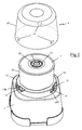
- the figure 1 represents a food preparation apparatus comprising a housing 1 comprising a body, having a substantially cubic external shape, enclosing a motor 2 whose output shaft is integral with a trainer 3 protruding from a receiving base 10 disposed at the upper end of the housing 1.
- the receiving base 10 supports a working bowl 4 having a bottom 40 provided with a central chimney 41 in which the coach 3 engages, the working bowl 4 having a lower face having a cavity 42, visible only on the figure 4 , in which is engaged a fingerprint 11 of complementary shape projecting on the receiving base 10 to ensure immobilization in rotation of the working bowl 4 on the housing 1.
- the work bowl 4 receives a fragmentation tool 5 comprising a hub 50 supporting two cutting blades 51 arranged opposite one another, the hub 50 engaging on the central shaft 41 and comprising an inner portion which mates with the drive 3.
- the working bowl 4 comprises a cylindrical wall 43 extending from the bottom 40 to an open upper end which is capped by a transparent cover 6, the cover 6 comprising a side skirt 60 surrounding the working bowl 4 and coming from engage around a conical centering portion 12 protruding from the receiving base 10.
- the conical centering portion 12 comprises three identical peripheral cutouts 13 spaced 120 ° from each other, the three cutouts 13 having an inclined edge forming a guide ramp to a groove formed on the peripheral surface of the conical centering portion 12 each groove having a lower edge provided with a slot 14 opening on a sliding rod mechanism 16, 17, 18 disposed inside the housing 1.
- One of the sliding rod mechanisms disposed behind a first cutout 13 located on one side of the front face of the housing 1, is constituted by a control rod 16, represented in dashed line on the figure 2 .
- This control rod 16 is carried by a frame, not shown in the figures, integrated in the housing 1, and is returned by a return spring 16A in a raised position, rest, in which the control rod 16 actuates no switch 20 present on the motor supply circuit 2. In this rest position, the power supply circuit of the motor 2 is cut and the motor 2 is stopped.
- the control rod 16 has an upper end provided with an operating key 16B which is accessible through the slot 14 of the blank 13, the control rod 16 moving downwards when a vertical pressure is exerted on the operating key 16B to occupy an operating position of the motor 2 in which the control rod 16 actuates the switch 20 of the supply circuit of the motor 2 to supply the latter with electricity.
- the second cutout 13 located on the other side of the front face of the housing 1 mask a safety rod 17, shown in dotted line on the figure 2 which cooperates with an electric braking device of the engine.
- the safety rod 17 is slidably mounted on a frame, not shown in the figures, disposed inside the housing 1 between a raised position, rest, to which it is brought by a return spring 17A, and a lowered position in which the braking device is switched off.
- the safety rod 17 has an upper end provided with an operating key 17B which is accessible through the slot 14 of the blank 13, the safety rod 17 moving downwards when a vertical pressure is exerted on the operating key 17B to occupy the lowered position.
- the electric braking device of the motor is constituted by a device for short-circuiting the armature of the motor, not visible in the figures, as described in more detail in the patent application. FR 2 140 891 .
- This short-circuiting of the armature of the motor is effected by means of two switches 21 which are actuated simultaneously by the safety rod 17 in such a way that the commissioning of the braking device is carried out during the return of the safety rod 17 in the rest position by inverting the electrical connection at the terminals of one of the coils of the motor 2.
- the return rod 18 comprises an upper end provided with an operating key 18B which is accessible through the third cutout 13 and whose purpose is to provide a third fulcrum providing a return force equivalent to that provided by control rods 16 and safety rods 17.
- the start of the motor 2 is controlled by means of a vertical displacement of the cover 6 in the direction of the housing 1, the cover 6 having tabs 61 engaging in the cutouts 13 to be positioned above the operating keys 16B, 17B, 18B.
- the return rod 18 allows to obtain a balanced support of the cover 6 on the three operating keys 16B, 17B, 18B so that the cover 6 remains in a horizontal position, the start of the engine 2 being performed conventionally by exerting a vertical pressure, to bottom, on the lid 6.
- the working bowl 4 receives a lid 7 closing the open upper end of the working bowl 4 to confine the ingredients inside the latter.
- this cover 7 advantageously has the shape of a disc, substantially flat, coming to rest on an upper edge 44 of the working bowl 4, the cover 7 having a peripheral groove 70 engaging on the upper edge 44 of the bowl of working and preferably having a peripheral skirt 71 coming to engage by elastic deformation around a bulge 44A of the upper edge of the wall 43, so that the lid 7 is clipped onto the working bowl 4.
- the cover 7 also has a central opening 72 allowing the passage of the upper end of the hub 50 of the fragmentation tool 5, the latter advantageously comprising a bearing 52 in which is engaged a central guide shaft 62 supported by the cover 6 when the cover 6 is brought on the housing 1.
- the central opening 72 of the cap preferably has a diameter slightly greater than the diameter of the upper end of the hub 50 of the fragmentation tool 5 so that the space between the hub 50 and the cap 7 is reduced.
- the central opening 72 of the lid advantageously extends through a cylindrical wall 73 extending a few millimeters inwardly of the working bowl 4 so as to form a screen against the projections of food of the interior of the working bowl 4 towards the space extending between the hub 50 and the cover 7.
- the cover 7 thus has the advantage of eliminating any risk of projection towards the guide axis 62 and the bearing 52, which ensures a perfect rotation of the fragmentation tool 5 at this link.
- the cover 7 is made of transparent plastic material, such as polypropylene, and has a thickness less than 1 mm and preferably of the order of 0.5 mm.
- the device is then actuated by pushing down on the cover 6 so that it moves vertically towards the casing 1, the tabs 61 of the cover 6 then operating simultaneously.
- the control rod 16 of the engine 2 and the safety rod 17 to simultaneously control the start of the engine 2 and the decommissioning of the braking means.
- the vertical displacement of the lid 6 is carried out until a shoulder 63 of the lid 6 abuts against the lid 7, relying on the surface of the lid 7 disposed opposite the upper edge 44 of the bowl 4, so that the lid 6 is in a lowered position in which it exerts pressure on the lid 7 ensuring a holding of the lid 7 on the working bowl 4 during mixing of food.
- the seal 7 forms a tight barrier preventing overflow outside the working bowl 4 under the effect of centrifugal force, especially in the case of mixing powders or liquid or semi-liquid preparations.
- cap 7 has the advantage of helping to promote the mixing of food by disturbing the mixing flow, the food being returned to the center of the work bowl 4 after rebounding against the operculum 7.
- control rods 16 and safety rods 17 are brought simultaneously into their rest position by their return spring 16A, 17A so that the power supply of the motor 2 is interrupted and the motor 2 is braked instantly by the braking device.
- the lid 7 remains in place on the working bowl 4 while being held both by its own weight and by the engagement of the peripheral skirt 71 on the bulge 44A of the bowl of job.
- the lid 7 thus continues to act as a sealing lid by preventing any overflow of food outside the working bowl 4 when the crushed food continues to circulate in the work bowl 4 shortly after the opening of the switch. 20 and that the mixing flow is disturbed by the abrupt stop of the fragmentation tool 5.
- the seal 7 has the advantage of being very simple to clean and inexpensive to manufacture, several lids 7 can be delivered with the device.
- Such an apparatus also has the advantage of great safety of use, the action of the braking device ensuring a downtime of the fragmentation tool 5 less than the time required for the user to remove the lid 6 and access the contents of the work bowl 4.
- the presence of the lid 7 on the work bowl 4 forms an additional safety barrier, notably preventing quick access to the contents of the work bowl 4.
- the apparatus thus produced may also operate in the absence of the lid 7 on the work bowl to avoid for example additional manipulations when the ingredients to be treated do not present a risk of overflow.
- the cover 6 can be removed from the receiving base 10 after a rotational movement of the cover 6, to extract the tabs 61 of the cuts 13, so that the time required to access the content of the working bowl 4 is large enough to guarantee the stop of the fragmentation tool 5 for the time necessary to extraction of the lid 6.
- the cover may have a wall 7 ', shown in dotted line on the figure 4 , penetrating inside the work bowl to reduce the volume of the mixing chamber and improve mixing when only small amounts of food are introduced into the work bowl.
- the lid may have a curved wall towards the lid to increase the volume of the mixing chamber.
Landscapes
- Engineering & Computer Science (AREA)
- Mechanical Engineering (AREA)
- Food Science & Technology (AREA)
- Food-Manufacturing Devices (AREA)
Claims (10)
- Elektrohaushaltsgerät für kulinarische Zubereitungen, umfassend ein Gehäuse (1), das einen Arbeitsbehälter (4) trägt, der ein Zerkleinerungswerkzeug (5) und einen abnehmbaren Deckel (6) aufnimmt, wobei der Arbeitsbehälter (4) einen Boden (40) und eine Wand (43) aufweist, die sich vom Boden (40) des Arbeitsbehälters (4) zu einem offenen oberen Ende erstreckt, wobei das Gehäuse (1) einen Motor (2) für den Antrieb des Zerkleinerungswerkzeugs (5) einschließt, dessen Betrieb durch eine Bewegung des Deckels (6) zwischen einer erhöhten Position, in der der Motor (2) stillsteht, und einer abgesenkten Position, in der der Motor (2) in Betrieb ist, gesteuert wird, dadurch gekennzeichnet, dass das Gerät eine abnehmbare Abdeckung (7) umfasst, die vom Deckel (6) unabhängig ist und auf der Wand (43) des Arbeitsbehälters (4) aufliegt, um wenigstens teilweise das offene obere Ende des Arbeitsbehälters (4) abzudecken.
- Elektrohaushaltsgerät für kulinarische Zubereitungen nach Anspruch 1, dadurch gekennzeichnet, dass die Wand (43) einen oberen Rand (44) umfasst, der das offene obere Ende begrenzt, und dadurch, dass die Abdeckung (7) auf dem oberen Rand (44) des Arbeitsbehälters (4) aufliegt.
- Elektrohaushaltsgerät für kulinarische Zubereitungen nach Anspruch 2, dadurch gekennzeichnet, dass die Abdeckung (7) eine Dicke von weniger als 1 mm aufweist.
- Elektrohaushaltsgerät für kulinarische Zubereitungen nach einem der Ansprüche 2 bis 3, dadurch gekennzeichnet, dass die Abdeckung (7) eine umlaufende Rille (70) umfasst, die sich auf dem oberen Rand (44) des Arbeitsbehälters (4) einfügt.
- Elektrohaushaltsgerät für kulinarische Zubereitungen nach einem der Ansprüche 2 bis 4, dadurch gekennzeichnet, dass die Abdeckung (7) durch elastische Verformung auf dem Arbeitsbehälter (4) festgehalten wird.
- Elektrohaushaltsgerät für kulinarische Zubereitungen nach einem der Ansprüche 2 bis 5, dadurch gekennzeichnet, dass der Deckel (6) eine Fläche (63) umfasst, die auf die Abdeckung (7) drückt, wenn sich der Deckel (6) in der abgesenkten Position befindet.
- Elektrohaushaltsgerät für kulinarische Zubereitungen nach einem der Ansprüche 1 oder 6, dadurch gekennzeichnet, dass das Zerkleinerungswerkzeug (5) eine Mittelnabe (50) umfasst, deren oberes Ende von einem Führungselement (62) geführt wird, das der Deckel (6) trägt, und dadurch, dass die Abdeckung (7) eine Mittelöffnung (72) für den Durchlass der Mittelnabe (50) des Zerkleinerungswerkzeugs (5) umfasst.
- Elektrohaushaltsgerät für kulinarische Zubereitungen nach einem der Ansprüche 1 bis 7, dadurch gekennzeichnet, dass der Arbeitsbehälter (4) eine Mixkammer rund um das Zerkleinerungswerkzeug (5) definiert, und dadurch, dass die Abdeckung (7) eine Wand (7') aufweist, die in das Innere des Arbeitsbehälters (4) eindringt, um das Volumen der Mixkammer zu verringern.
- Elektrohaushaltsgerät für kulinarische Zubereitungen nach einem der Ansprüche 1 bis 8, dadurch gekennzeichnet, dass der Deckel (6) eine Schürze (60) umfasst, die den Arbeitsbehälter (4) seitlich umhüllt, wobei die Schürze (60) wenigstens eine vom Gehäuse getragene Betätigungstaste (16B) betätigt, um einen Schalter (20) zu betätigen und die Inbetriebsetzung des Motors (2) zu steuern, wenn auf den Deckel (6) ein senkrechter Druck manuell ausgeübt wird.
- Elektrohaushaltsgerät für kulinarische Zubereitungen nach Anspruch 9, dadurch gekennzeichnet, dass es eine Bremsvorrichtung umfasst, die verhindert, dass der Motor (2) nach dem durch den Schalter (20) gegebenen Befehl für die Abschaltung des Motors (2) aufgrund seiner Trägheit weiterläuft.
Applications Claiming Priority (1)
| Application Number | Priority Date | Filing Date | Title |
|---|---|---|---|
| FR1052016A FR2957509B1 (fr) | 2010-03-22 | 2010-03-22 | Appareil electromenager de preparation culinaire comportant un boitier supportant un bol de travail recevant un outil de fragmentation |
Publications (2)
| Publication Number | Publication Date |
|---|---|
| EP2368470A1 EP2368470A1 (de) | 2011-09-28 |
| EP2368470B1 true EP2368470B1 (de) | 2013-08-28 |
Family
ID=42931836
Family Applications (1)
| Application Number | Title | Priority Date | Filing Date |
|---|---|---|---|
| EP20110305287 Active EP2368470B1 (de) | 2010-03-22 | 2011-03-15 | Elektrohaushaltsgerät zur Essenzubereitung, das ein Gehäuse mit einer Arbeitsschüsselhalterung und einem Zerkleinerungswerkzeug zum Einführen in die Schüssel umfasst |
Country Status (5)
| Country | Link |
|---|---|
| EP (1) | EP2368470B1 (de) |
| CN (1) | CN102197964B (de) |
| ES (1) | ES2436593T3 (de) |
| FR (1) | FR2957509B1 (de) |
| PT (1) | PT2368470E (de) |
Cited By (1)
| Publication number | Priority date | Publication date | Assignee | Title |
|---|---|---|---|---|
| CN107666845A (zh) * | 2015-05-28 | 2018-02-06 | 沙克忍者运营有限责任公司 | 用于搅拌机系统的研磨器附件 |
Families Citing this family (12)
| Publication number | Priority date | Publication date | Assignee | Title |
|---|---|---|---|---|
| US10449685B2 (en) | 2010-04-29 | 2019-10-22 | Whirlpool Corporation | Food processor with adjustable blade assembly |
| US8720325B2 (en) | 2010-04-29 | 2014-05-13 | Whirlpool Corporation | Food processor with a lockable adjustable blade assembly |
| FR2998466B1 (fr) * | 2012-11-29 | 2015-05-29 | Hameur Sa | Appareil de traitement d'aliments a outil equilibre |
| FR2999404B1 (fr) * | 2012-12-14 | 2014-12-26 | Seb Sa | Appareil electromenager comportant un couvercle interne d’etancheite |
| FR2999406B1 (fr) * | 2012-12-14 | 2014-12-26 | Seb Sa | Couvercle d’appareil electromenager comportant une face interne presentant un etat de surface ameliore |
| FR3003457B1 (fr) * | 2013-03-22 | 2015-11-13 | Seb Sa | Appareil de preparation culinaire electrique avec recipient de travail |
| FR3009942B1 (fr) * | 2013-08-29 | 2015-09-25 | Seb Sa | Appareil electromenager de preparation culinaire comportant un outil de travail venant s'engager de maniere amovible sur un entraineur |
| US20150250360A1 (en) * | 2014-03-07 | 2015-09-10 | Euro-Pro Operating Llc | Blender |
| US10085599B2 (en) | 2014-12-19 | 2018-10-02 | Whirlpool Corporation | Multi-cook and food processing prep product |
| USD787883S1 (en) | 2015-05-28 | 2017-05-30 | Sharkninja Operating, Llc | Blender attachment |
| DE102016110827A1 (de) * | 2016-06-13 | 2017-12-14 | Vorwerk & Co. Interholding Gmbh | Elektromotorisch betriebene Küchenmaschine |
| CA3044579C (en) | 2016-11-24 | 2023-10-10 | Sharkninja Operating Llc | Blender interlock |
Family Cites Families (7)
| Publication number | Priority date | Publication date | Assignee | Title |
|---|---|---|---|---|
| FR2140891A5 (de) | 1971-06-11 | 1973-01-19 | Moulinex Sa | |
| FR2340707A1 (fr) * | 1976-02-10 | 1977-09-09 | Moulinex Sa | Appareil menager electrique, tel qu'un hachoir ou broyeur |
| EP0004987B1 (de) * | 1978-04-19 | 1981-09-02 | Braun Aktiengesellschaft | Elektrischer Haushalts-Mischzerkleinerer |
| FR2729588B1 (fr) * | 1995-01-24 | 1997-06-13 | Moulinex Sa | Appareil menager a couteau rotatif, tel qu'un hachoir |
| JPH08215075A (ja) * | 1995-02-15 | 1996-08-27 | Matsushita Electric Ind Co Ltd | 電動調理器 |
| FR2753621B1 (fr) * | 1996-09-20 | 1998-12-18 | Appareil electromenager pour le traitement d'aliments comportant un dispositif de rangement des outils de travail | |
| JP2008245786A (ja) * | 2007-03-29 | 2008-10-16 | Iwatani Internatl Corp | 電動式食材おろし器 |
-
2010
- 2010-03-22 FR FR1052016A patent/FR2957509B1/fr not_active Expired - Fee Related
-
2011
- 2011-03-15 ES ES11305287T patent/ES2436593T3/es active Active
- 2011-03-15 EP EP20110305287 patent/EP2368470B1/de active Active
- 2011-03-15 PT PT11305287T patent/PT2368470E/pt unknown
- 2011-03-21 CN CN201110067390.0A patent/CN102197964B/zh active Active
Cited By (1)
| Publication number | Priority date | Publication date | Assignee | Title |
|---|---|---|---|---|
| CN107666845A (zh) * | 2015-05-28 | 2018-02-06 | 沙克忍者运营有限责任公司 | 用于搅拌机系统的研磨器附件 |
Also Published As
| Publication number | Publication date |
|---|---|
| EP2368470A1 (de) | 2011-09-28 |
| PT2368470E (pt) | 2013-11-29 |
| CN102197964A (zh) | 2011-09-28 |
| CN102197964B (zh) | 2015-03-11 |
| ES2436593T3 (es) | 2014-01-03 |
| FR2957509A1 (fr) | 2011-09-23 |
| FR2957509B1 (fr) | 2012-03-23 |
Similar Documents
| Publication | Publication Date | Title |
|---|---|---|
| EP2368470B1 (de) | Elektrohaushaltsgerät zur Essenzubereitung, das ein Gehäuse mit einer Arbeitsschüsselhalterung und einem Zerkleinerungswerkzeug zum Einführen in die Schüssel umfasst | |
| EP3075295B1 (de) | Elektrohaushaltsgerät zur essenszubereitung, das einen deckel mit einem abzug zum einfüllen von lebensmitteln umfasst | |
| EP2085005B1 (de) | Elektrisches Haushaltsgerät zur Essenszubereitung, das ein Gehäuse mit einem Motor und einem Behälter umfasst, in den ein Rührwerkzeug eingeführt werden kann | |
| EP2687132B1 (de) | Druckkochgerät mit verbesserter Bedienungsvorrichtung | |
| EP0805641B1 (de) | Küchengerät mit drehendem messer, wie ein häcksler | |
| WO2013041466A1 (fr) | Appareil electromenager comprenant un recipient de travail muni d'un filtre | |
| EP2923621B1 (de) | Elektrohaushaltsgerät zur essenszubereitung, das einen behälter umfasst, der mit einem abnehmbaren deckel verschlossen ist, der mit einer sicherheitsvorrichtung kombiniert ist | |
| WO2014087077A1 (fr) | Appareil electromenager de preparation culinaire comportant un recipient de travail comprenant un panier pour la cuisson a la vapeur | |
| EP2206455A1 (de) | Haushaltsgerät zur Essenszubereitung, das einen ersten und einen zweiten Arbeitsbehälter auf einem Gehäuse umfasst | |
| EP2130470B1 (de) | Arbeitsbehälter, der eine abnehmbare Werkzeughalterungsplatte umfasst, und Elektrohaushaltsgerät zur Essenszubereitung, das mit einem solchen Behälter ausgestattet ist | |
| EP2651273A1 (de) | Elektrische küchenmaschine mit einem sockel für eine schüssel und einem fix mit dem sockel verbundenen arm | |
| EP2368469B1 (de) | Elektrohaushaltsgerät zur Essenzubereitung, das ein Motorgehäuse zur Aufnahme von verschiedenen Typen von auswechselbaren Zubehörteilen umfasst | |
| EP1711091B1 (de) | Elektrisches haushaltsgerät zur nahrungsmittelzubereitung mit einem entfernbaren zubehörteil mit einer steuervorrichtung | |
| EP2651272B1 (de) | Elektrische küchenmaschine mit einem sockel für eine mit einem abnehmbarem deckel verschliessbare schüssel | |
| EP2937027B1 (de) | Elektrohaushaltsgerät zur essenszubereitung, das einen entfernbaren behälter umfasst, der durch eine einfache verschiebungsbewegung auf einem gehäuse abgestellt werden kann | |
| EP2005868B1 (de) | Hahn zur Verteilung von in einem Behälter enthaltenen Lebensmitteln und Haushaltsgerät zum Kochen, das mit einem solchen Hahn ausgestattet ist | |
| EP1185820A1 (de) | Mechanische sicherheitsvorrichtung für ein gerät zur behandlung von nahrungsmitteln | |
| EP1809155A1 (de) | Elektrisches haushaltsgerät zur herstellung von lebensmitteln mit einer basis mit verschieden geformten aussparungen |
Legal Events
| Date | Code | Title | Description |
|---|---|---|---|
| PUAI | Public reference made under article 153(3) epc to a published international application that has entered the european phase |
Free format text: ORIGINAL CODE: 0009012 |
|
| AK | Designated contracting states |
Kind code of ref document: A1 Designated state(s): AL AT BE BG CH CY CZ DE DK EE ES FI FR GB GR HR HU IE IS IT LI LT LU LV MC MK MT NL NO PL PT RO RS SE SI SK SM TR |
|
| AX | Request for extension of the european patent |
Extension state: BA ME |
|
| 17P | Request for examination filed |
Effective date: 20120316 |
|
| GRAP | Despatch of communication of intention to grant a patent |
Free format text: ORIGINAL CODE: EPIDOSNIGR1 |
|
| RIC1 | Information provided on ipc code assigned before grant |
Ipc: A47J 43/08 20060101ALI20130508BHEP Ipc: A47J 43/046 20060101ALI20130508BHEP Ipc: A47J 43/07 20060101AFI20130508BHEP Ipc: A47J 43/06 20060101ALI20130508BHEP |
|
| INTG | Intention to grant announced |
Effective date: 20130527 |
|
| RIN1 | Information on inventor provided before grant (corrected) |
Inventor name: LEMARIE, CHRISTOPHE Inventor name: BEUNACHE, MICHELE |
|
| GRAS | Grant fee paid |
Free format text: ORIGINAL CODE: EPIDOSNIGR3 |
|
| GRAA | (expected) grant |
Free format text: ORIGINAL CODE: 0009210 |
|
| AK | Designated contracting states |
Kind code of ref document: B1 Designated state(s): AL AT BE BG CH CY CZ DE DK EE ES FI FR GB GR HR HU IE IS IT LI LT LU LV MC MK MT NL NO PL PT RO RS SE SI SK SM TR |
|
| REG | Reference to a national code |
Ref country code: GB Ref legal event code: FG4D Free format text: NOT ENGLISH |
|
| REG | Reference to a national code |
Ref country code: CH Ref legal event code: EP |
|
| REG | Reference to a national code |
Ref country code: AT Ref legal event code: REF Ref document number: 628828 Country of ref document: AT Kind code of ref document: T Effective date: 20130915 |
|
| REG | Reference to a national code |
Ref country code: IE Ref legal event code: FG4D Free format text: LANGUAGE OF EP DOCUMENT: FRENCH |
|
| REG | Reference to a national code |
Ref country code: DE Ref legal event code: R096 Ref document number: 602011002845 Country of ref document: DE Effective date: 20131024 |
|
| REG | Reference to a national code |
Ref country code: PT Ref legal event code: SC4A Free format text: AVAILABILITY OF NATIONAL TRANSLATION Effective date: 20131122 |
|
| REG | Reference to a national code |
Ref country code: ES Ref legal event code: FG2A Ref document number: 2436593 Country of ref document: ES Kind code of ref document: T3 Effective date: 20140103 |
|
| REG | Reference to a national code |
Ref country code: AT Ref legal event code: MK05 Ref document number: 628828 Country of ref document: AT Kind code of ref document: T Effective date: 20130828 |
|
| REG | Reference to a national code |
Ref country code: LT Ref legal event code: MG4D |
|
| REG | Reference to a national code |
Ref country code: NL Ref legal event code: VDEP Effective date: 20130828 |
|
| PG25 | Lapsed in a contracting state [announced via postgrant information from national office to epo] |
Ref country code: SE Free format text: LAPSE BECAUSE OF FAILURE TO SUBMIT A TRANSLATION OF THE DESCRIPTION OR TO PAY THE FEE WITHIN THE PRESCRIBED TIME-LIMIT Effective date: 20130828 Ref country code: LT Free format text: LAPSE BECAUSE OF FAILURE TO SUBMIT A TRANSLATION OF THE DESCRIPTION OR TO PAY THE FEE WITHIN THE PRESCRIBED TIME-LIMIT Effective date: 20130828 Ref country code: HR Free format text: LAPSE BECAUSE OF FAILURE TO SUBMIT A TRANSLATION OF THE DESCRIPTION OR TO PAY THE FEE WITHIN THE PRESCRIBED TIME-LIMIT Effective date: 20130828 Ref country code: AT Free format text: LAPSE BECAUSE OF FAILURE TO SUBMIT A TRANSLATION OF THE DESCRIPTION OR TO PAY THE FEE WITHIN THE PRESCRIBED TIME-LIMIT Effective date: 20130828 Ref country code: IS Free format text: LAPSE BECAUSE OF FAILURE TO SUBMIT A TRANSLATION OF THE DESCRIPTION OR TO PAY THE FEE WITHIN THE PRESCRIBED TIME-LIMIT Effective date: 20131228 Ref country code: CY Free format text: LAPSE BECAUSE OF FAILURE TO SUBMIT A TRANSLATION OF THE DESCRIPTION OR TO PAY THE FEE WITHIN THE PRESCRIBED TIME-LIMIT Effective date: 20130619 Ref country code: NO Free format text: LAPSE BECAUSE OF FAILURE TO SUBMIT A TRANSLATION OF THE DESCRIPTION OR TO PAY THE FEE WITHIN THE PRESCRIBED TIME-LIMIT Effective date: 20131128 |
|
| REG | Reference to a national code |
Ref country code: NL Ref legal event code: VDEP Effective date: 20130828 |
|
| PG25 | Lapsed in a contracting state [announced via postgrant information from national office to epo] |
Ref country code: GR Free format text: LAPSE BECAUSE OF FAILURE TO SUBMIT A TRANSLATION OF THE DESCRIPTION OR TO PAY THE FEE WITHIN THE PRESCRIBED TIME-LIMIT Effective date: 20131129 Ref country code: FI Free format text: LAPSE BECAUSE OF FAILURE TO SUBMIT A TRANSLATION OF THE DESCRIPTION OR TO PAY THE FEE WITHIN THE PRESCRIBED TIME-LIMIT Effective date: 20130828 Ref country code: PL Free format text: LAPSE BECAUSE OF FAILURE TO SUBMIT A TRANSLATION OF THE DESCRIPTION OR TO PAY THE FEE WITHIN THE PRESCRIBED TIME-LIMIT Effective date: 20130828 Ref country code: SI Free format text: LAPSE BECAUSE OF FAILURE TO SUBMIT A TRANSLATION OF THE DESCRIPTION OR TO PAY THE FEE WITHIN THE PRESCRIBED TIME-LIMIT Effective date: 20130828 Ref country code: LV Free format text: LAPSE BECAUSE OF FAILURE TO SUBMIT A TRANSLATION OF THE DESCRIPTION OR TO PAY THE FEE WITHIN THE PRESCRIBED TIME-LIMIT Effective date: 20130828 |
|
| PG25 | Lapsed in a contracting state [announced via postgrant information from national office to epo] |
Ref country code: CY Free format text: LAPSE BECAUSE OF FAILURE TO SUBMIT A TRANSLATION OF THE DESCRIPTION OR TO PAY THE FEE WITHIN THE PRESCRIBED TIME-LIMIT Effective date: 20130828 |
|
| PG25 | Lapsed in a contracting state [announced via postgrant information from national office to epo] |
Ref country code: SK Free format text: LAPSE BECAUSE OF FAILURE TO SUBMIT A TRANSLATION OF THE DESCRIPTION OR TO PAY THE FEE WITHIN THE PRESCRIBED TIME-LIMIT Effective date: 20130828 Ref country code: RO Free format text: LAPSE BECAUSE OF FAILURE TO SUBMIT A TRANSLATION OF THE DESCRIPTION OR TO PAY THE FEE WITHIN THE PRESCRIBED TIME-LIMIT Effective date: 20130828 Ref country code: NL Free format text: LAPSE BECAUSE OF FAILURE TO SUBMIT A TRANSLATION OF THE DESCRIPTION OR TO PAY THE FEE WITHIN THE PRESCRIBED TIME-LIMIT Effective date: 20130828 Ref country code: DK Free format text: LAPSE BECAUSE OF FAILURE TO SUBMIT A TRANSLATION OF THE DESCRIPTION OR TO PAY THE FEE WITHIN THE PRESCRIBED TIME-LIMIT Effective date: 20130828 Ref country code: CZ Free format text: LAPSE BECAUSE OF FAILURE TO SUBMIT A TRANSLATION OF THE DESCRIPTION OR TO PAY THE FEE WITHIN THE PRESCRIBED TIME-LIMIT Effective date: 20130828 Ref country code: EE Free format text: LAPSE BECAUSE OF FAILURE TO SUBMIT A TRANSLATION OF THE DESCRIPTION OR TO PAY THE FEE WITHIN THE PRESCRIBED TIME-LIMIT Effective date: 20130828 |
|
| REG | Reference to a national code |
Ref country code: DE Ref legal event code: R097 Ref document number: 602011002845 Country of ref document: DE |
|
| PLBE | No opposition filed within time limit |
Free format text: ORIGINAL CODE: 0009261 |
|
| STAA | Information on the status of an ep patent application or granted ep patent |
Free format text: STATUS: NO OPPOSITION FILED WITHIN TIME LIMIT |
|
| 26N | No opposition filed |
Effective date: 20140530 |
|
| REG | Reference to a national code |
Ref country code: DE Ref legal event code: R097 Ref document number: 602011002845 Country of ref document: DE Effective date: 20140530 |
|
| PG25 | Lapsed in a contracting state [announced via postgrant information from national office to epo] |
Ref country code: LU Free format text: LAPSE BECAUSE OF FAILURE TO SUBMIT A TRANSLATION OF THE DESCRIPTION OR TO PAY THE FEE WITHIN THE PRESCRIBED TIME-LIMIT Effective date: 20140315 |
|
| REG | Reference to a national code |
Ref country code: CH Ref legal event code: PL |
|
| REG | Reference to a national code |
Ref country code: IE Ref legal event code: MM4A |
|
| PG25 | Lapsed in a contracting state [announced via postgrant information from national office to epo] |
Ref country code: CH Free format text: LAPSE BECAUSE OF NON-PAYMENT OF DUE FEES Effective date: 20140331 Ref country code: LI Free format text: LAPSE BECAUSE OF NON-PAYMENT OF DUE FEES Effective date: 20140331 Ref country code: IE Free format text: LAPSE BECAUSE OF NON-PAYMENT OF DUE FEES Effective date: 20140315 |
|
| GBPC | Gb: european patent ceased through non-payment of renewal fee |
Effective date: 20150315 |
|
| PG25 | Lapsed in a contracting state [announced via postgrant information from national office to epo] |
Ref country code: GB Free format text: LAPSE BECAUSE OF NON-PAYMENT OF DUE FEES Effective date: 20150315 |
|
| PG25 | Lapsed in a contracting state [announced via postgrant information from national office to epo] |
Ref country code: MT Free format text: LAPSE BECAUSE OF FAILURE TO SUBMIT A TRANSLATION OF THE DESCRIPTION OR TO PAY THE FEE WITHIN THE PRESCRIBED TIME-LIMIT Effective date: 20130828 |
|
| REG | Reference to a national code |
Ref country code: FR Ref legal event code: PLFP Year of fee payment: 6 |
|
| PG25 | Lapsed in a contracting state [announced via postgrant information from national office to epo] |
Ref country code: SM Free format text: LAPSE BECAUSE OF FAILURE TO SUBMIT A TRANSLATION OF THE DESCRIPTION OR TO PAY THE FEE WITHIN THE PRESCRIBED TIME-LIMIT Effective date: 20130828 |
|
| PG25 | Lapsed in a contracting state [announced via postgrant information from national office to epo] |
Ref country code: MC Free format text: LAPSE BECAUSE OF FAILURE TO SUBMIT A TRANSLATION OF THE DESCRIPTION OR TO PAY THE FEE WITHIN THE PRESCRIBED TIME-LIMIT Effective date: 20130828 |
|
| PG25 | Lapsed in a contracting state [announced via postgrant information from national office to epo] |
Ref country code: BG Free format text: LAPSE BECAUSE OF FAILURE TO SUBMIT A TRANSLATION OF THE DESCRIPTION OR TO PAY THE FEE WITHIN THE PRESCRIBED TIME-LIMIT Effective date: 20130828 Ref country code: RS Free format text: LAPSE BECAUSE OF FAILURE TO SUBMIT A TRANSLATION OF THE DESCRIPTION OR TO PAY THE FEE WITHIN THE PRESCRIBED TIME-LIMIT Effective date: 20130828 |
|
| PG25 | Lapsed in a contracting state [announced via postgrant information from national office to epo] |
Ref country code: TR Free format text: LAPSE BECAUSE OF FAILURE TO SUBMIT A TRANSLATION OF THE DESCRIPTION OR TO PAY THE FEE WITHIN THE PRESCRIBED TIME-LIMIT Effective date: 20130828 Ref country code: HU Free format text: LAPSE BECAUSE OF FAILURE TO SUBMIT A TRANSLATION OF THE DESCRIPTION OR TO PAY THE FEE WITHIN THE PRESCRIBED TIME-LIMIT; INVALID AB INITIO Effective date: 20110315 |
|
| REG | Reference to a national code |
Ref country code: FR Ref legal event code: PLFP Year of fee payment: 7 |
|
| REG | Reference to a national code |
Ref country code: FR Ref legal event code: CA Effective date: 20170518 |
|
| REG | Reference to a national code |
Ref country code: FR Ref legal event code: PLFP Year of fee payment: 8 |
|
| PG25 | Lapsed in a contracting state [announced via postgrant information from national office to epo] |
Ref country code: MK Free format text: LAPSE BECAUSE OF FAILURE TO SUBMIT A TRANSLATION OF THE DESCRIPTION OR TO PAY THE FEE WITHIN THE PRESCRIBED TIME-LIMIT Effective date: 20130828 |
|
| PG25 | Lapsed in a contracting state [announced via postgrant information from national office to epo] |
Ref country code: AL Free format text: LAPSE BECAUSE OF FAILURE TO SUBMIT A TRANSLATION OF THE DESCRIPTION OR TO PAY THE FEE WITHIN THE PRESCRIBED TIME-LIMIT Effective date: 20130828 |
|
| PGFP | Annual fee paid to national office [announced via postgrant information from national office to epo] |
Ref country code: DE Payment date: 20240307 Year of fee payment: 14 Ref country code: PT Payment date: 20240220 Year of fee payment: 14 |
|
| PGFP | Annual fee paid to national office [announced via postgrant information from national office to epo] |
Ref country code: IT Payment date: 20240311 Year of fee payment: 14 Ref country code: FR Payment date: 20240325 Year of fee payment: 14 Ref country code: BE Payment date: 20240326 Year of fee payment: 14 |
|
| PGFP | Annual fee paid to national office [announced via postgrant information from national office to epo] |
Ref country code: ES Payment date: 20240405 Year of fee payment: 14 |